EP1996839B1 - Mechanical seal with enhanced face stability - Google Patents
Mechanical seal with enhanced face stability Download PDFInfo
- Publication number
- EP1996839B1 EP1996839B1 EP07758154A EP07758154A EP1996839B1 EP 1996839 B1 EP1996839 B1 EP 1996839B1 EP 07758154 A EP07758154 A EP 07758154A EP 07758154 A EP07758154 A EP 07758154A EP 1996839 B1 EP1996839 B1 EP 1996839B1
- Authority
- EP
- European Patent Office
- Prior art keywords
- foot portion
- seal
- shell
- ring
- seal assembly
- Prior art date
- Legal status (The legal status is an assumption and is not a legal conclusion. Google has not performed a legal analysis and makes no representation as to the accuracy of the status listed.)
- Active
Links
- 230000013011 mating Effects 0.000 claims description 32
- 229910045601 alloy Inorganic materials 0.000 claims description 18
- 239000000956 alloy Substances 0.000 claims description 18
- 210000000689 upper leg Anatomy 0.000 claims description 9
- 230000004323 axial length Effects 0.000 claims description 8
- 230000005484 gravity Effects 0.000 claims description 7
- 230000015572 biosynthetic process Effects 0.000 claims 2
- 239000011257 shell material Substances 0.000 description 78
- 208000035187 Ring chromosome 14 syndrome Diseases 0.000 description 34
- 238000000034 method Methods 0.000 description 20
- 230000008569 process Effects 0.000 description 19
- 238000009826 distribution Methods 0.000 description 18
- 239000000463 material Substances 0.000 description 18
- 239000007788 liquid Substances 0.000 description 13
- OKTJSMMVPCPJKN-UHFFFAOYSA-N Carbon Chemical compound [C] OKTJSMMVPCPJKN-UHFFFAOYSA-N 0.000 description 11
- 238000010276 construction Methods 0.000 description 11
- 230000004888 barrier function Effects 0.000 description 9
- 229910052799 carbon Inorganic materials 0.000 description 8
- 238000010586 diagram Methods 0.000 description 7
- 230000000712 assembly Effects 0.000 description 6
- 238000000429 assembly Methods 0.000 description 6
- 238000007789 sealing Methods 0.000 description 6
- 239000012530 fluid Substances 0.000 description 5
- 238000005457 optimization Methods 0.000 description 5
- -1 AM 350 Inorganic materials 0.000 description 4
- 229910001203 Alloy 20 Inorganic materials 0.000 description 3
- 238000005452 bending Methods 0.000 description 3
- 230000008859 change Effects 0.000 description 3
- 230000007423 decrease Effects 0.000 description 3
- 229910002804 graphite Inorganic materials 0.000 description 3
- 239000010439 graphite Substances 0.000 description 3
- 229910000856 hastalloy Inorganic materials 0.000 description 3
- 229910052710 silicon Inorganic materials 0.000 description 3
- 239000010703 silicon Substances 0.000 description 3
- HBMJWWWQQXIZIP-UHFFFAOYSA-N silicon carbide Chemical compound [Si+]#[C-] HBMJWWWQQXIZIP-UHFFFAOYSA-N 0.000 description 3
- 229910001220 stainless steel Inorganic materials 0.000 description 3
- 239000010935 stainless steel Substances 0.000 description 3
- 229910000906 Bronze Inorganic materials 0.000 description 2
- VYZAMTAEIAYCRO-UHFFFAOYSA-N Chromium Chemical compound [Cr] VYZAMTAEIAYCRO-UHFFFAOYSA-N 0.000 description 2
- ATUOYWHBWRKTHZ-UHFFFAOYSA-N Propane Chemical compound CCC ATUOYWHBWRKTHZ-UHFFFAOYSA-N 0.000 description 2
- 230000008901 benefit Effects 0.000 description 2
- 239000010974 bronze Substances 0.000 description 2
- 239000002131 composite material Substances 0.000 description 2
- KUNSUQLRTQLHQQ-UHFFFAOYSA-N copper tin Chemical compound [Cu].[Sn] KUNSUQLRTQLHQQ-UHFFFAOYSA-N 0.000 description 2
- 150000007524 organic acids Chemical class 0.000 description 2
- 235000005985 organic acids Nutrition 0.000 description 2
- 238000007747 plating Methods 0.000 description 2
- 229910010271 silicon carbide Inorganic materials 0.000 description 2
- UONOETXJSWQNOL-UHFFFAOYSA-N tungsten carbide Chemical compound [W+]#[C-] UONOETXJSWQNOL-UHFFFAOYSA-N 0.000 description 2
- XUIMIQQOPSSXEZ-UHFFFAOYSA-N Silicon Chemical compound [Si] XUIMIQQOPSSXEZ-UHFFFAOYSA-N 0.000 description 1
- NINIDFKCEFEMDL-UHFFFAOYSA-N Sulfur Chemical class [S] NINIDFKCEFEMDL-UHFFFAOYSA-N 0.000 description 1
- 230000033228 biological regulation Effects 0.000 description 1
- 239000001273 butane Substances 0.000 description 1
- 230000006835 compression Effects 0.000 description 1
- 238000007906 compression Methods 0.000 description 1
- 230000008602 contraction Effects 0.000 description 1
- 238000001816 cooling Methods 0.000 description 1
- 230000003247 decreasing effect Effects 0.000 description 1
- 238000004821 distillation Methods 0.000 description 1
- 230000009977 dual effect Effects 0.000 description 1
- 230000000694 effects Effects 0.000 description 1
- 230000036541 health Effects 0.000 description 1
- 238000010438 heat treatment Methods 0.000 description 1
- 239000001307 helium Substances 0.000 description 1
- 229910052734 helium Inorganic materials 0.000 description 1
- SWQJXJOGLNCZEY-UHFFFAOYSA-N helium atom Chemical compound [He] SWQJXJOGLNCZEY-UHFFFAOYSA-N 0.000 description 1
- 238000005304 joining Methods 0.000 description 1
- 239000002184 metal Substances 0.000 description 1
- 229910052751 metal Inorganic materials 0.000 description 1
- 238000005272 metallurgy Methods 0.000 description 1
- 238000012986 modification Methods 0.000 description 1
- 230000004048 modification Effects 0.000 description 1
- IJDNQMDRQITEOD-UHFFFAOYSA-N n-butane Chemical compound CCCC IJDNQMDRQITEOD-UHFFFAOYSA-N 0.000 description 1
- OFBQJSOFQDEBGM-UHFFFAOYSA-N n-pentane Natural products CCCCC OFBQJSOFQDEBGM-UHFFFAOYSA-N 0.000 description 1
- 230000009972 noncorrosive effect Effects 0.000 description 1
- 239000001294 propane Substances 0.000 description 1
- 238000000926 separation method Methods 0.000 description 1
- 230000003068 static effect Effects 0.000 description 1
- 239000000126 substance Substances 0.000 description 1
- 150000003464 sulfur compounds Chemical class 0.000 description 1
- 231100000331 toxic Toxicity 0.000 description 1
- 230000002588 toxic effect Effects 0.000 description 1
- 229910052721 tungsten Inorganic materials 0.000 description 1
- 239000010937 tungsten Substances 0.000 description 1
Images


Classifications
-
- F—MECHANICAL ENGINEERING; LIGHTING; HEATING; WEAPONS; BLASTING
- F16—ENGINEERING ELEMENTS AND UNITS; GENERAL MEASURES FOR PRODUCING AND MAINTAINING EFFECTIVE FUNCTIONING OF MACHINES OR INSTALLATIONS; THERMAL INSULATION IN GENERAL
- F16J—PISTONS; CYLINDERS; SEALINGS
- F16J15/00—Sealings
- F16J15/16—Sealings between relatively-moving surfaces
- F16J15/34—Sealings between relatively-moving surfaces with slip-ring pressed against a more or less radial face on one member
- F16J15/36—Sealings between relatively-moving surfaces with slip-ring pressed against a more or less radial face on one member connected by a diaphragm or bellow to the other member
- F16J15/363—Sealings between relatively-moving surfaces with slip-ring pressed against a more or less radial face on one member connected by a diaphragm or bellow to the other member the diaphragm or bellow being made of metal
-
- F—MECHANICAL ENGINEERING; LIGHTING; HEATING; WEAPONS; BLASTING
- F16—ENGINEERING ELEMENTS AND UNITS; GENERAL MEASURES FOR PRODUCING AND MAINTAINING EFFECTIVE FUNCTIONING OF MACHINES OR INSTALLATIONS; THERMAL INSULATION IN GENERAL
- F16J—PISTONS; CYLINDERS; SEALINGS
- F16J15/00—Sealings
- F16J15/16—Sealings between relatively-moving surfaces
- F16J15/34—Sealings between relatively-moving surfaces with slip-ring pressed against a more or less radial face on one member
- F16J15/3464—Mounting of the seal
- F16J15/3468—Means for controlling the deformations of the contacting faces
Definitions
- This invention relates to mechanical end face seal assemblies. More particularly, it relates to seal assemblies suitable for applications to a wide range of temperature and pressure operating environments.
- Mechanical end face seal assemblies are known and represent a successful solution to product leakage. Mechanical end face seal assemblies find wide applications in sealing liquids in pumps having a housing and an extending rotating shaft.
- the seal assemblies usually include a pair of annular seal rings that define a pair of relatively radial annular seal faces urged together to define a sealing interface. These seal rings are supported on the shaft and housing by assembly components.
- One seal ring, the primary ring, is axially movable and is urged by a compression spring or a metal bellows into face-to-face contact with the other seal ring, the mating ring, which is fixed against axial movement.
- the seal assembly can include either a single seal or a double seal where a buffer fluid pressure is supplied at a pressure higher than the process fluid to be sealed in order to prevent leakage of the process fluid across the seal ring face.
- Such mechanical seals are available from John Crane, Inc. and are disclosed in U.S. Patent Nos. 5,901,965 and 5,954,341 .
- the present invention represents a refinement in the mechanical seals of the type in U.S. Patent Nos. 5,901,965 and 5,954,341 .
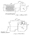
- Figure 1 shows a conventional (prior art) primary ring assembly 510 of a mechanical seal.
- the primary ring assembly 510 of the mechanical seal includes a primary ring 514 fitted against a primary ring shell 512 using a press fitting or a thermal shrink fitting technique, and a bellows 516 attached to a side of primary ring shell 512.
- Press fitting or thermal shrink fitting provides a very tight interference fit between primary ring 514 and primary ring shell 512, wherein primary ring 514 is radially and axially fixed to primary ring shell 512.
- mating parts on which the outer dimension of the interior member is the same as or slightly greater than the interior dimension of the exterior member, are forced together.
- the parts are joined by contracting (shrinking) the interior part by cooling and inserting the interior part into the exterior part. Subsequent expansion of the interior part by its return to ambient temperature ensures a tight fit.
- the parts are joined by expanding the exterior part by heating and inserting the interior part into the exterior part. Subsequent contraction of the exterior part by its return to ambient temperature ensures a tight fit.
- the interference fit between primary ring 514 and primary ring shell 512 acts as a secondary static seal prohibiting sealed process fluid from leaking between primary ring 514 and primary ring shell 512. Also, the contact friction between primary ring 514 and primary ring shell 512 caused by the interference fit prohibits relative circumferential movement of primary ring 514 with respect to primary ring shell 512.
- Other prior art seals are disclosed in the documents US-A-3560004 , US-A-294182S , US-A-3131941 , US-A1-2002074732 and US-A-4335888 .
- the amount of interference for a given seal size depends on the nominal interference diameter, the differential thermal expansion coefficients of the shell and primary ring materials of construction, and the maximum operating temperature.
- the representative values of the thermal expansion coefficient of some typical shell and primary ring materials are presented in Table 1.
- Alloy 718 and Alloy 42 possible materials for forming the shell, are well known alloys and are commercially available from several material suppliers. As seen, Alloy-42 has a low coefficient of thermal expansion that closely matches that of the primary ring materials and hence, is sometimes a good choice as the shell material of construction. Unfortunately, the high temperature applications containing corrosive organic acids and high sulfur compounds tend to readily corrode the Alloy-42 shell. A common industry practice is to apply chrome plating to the Alloy-42 shell component to protect it from corrosive attack. However, such chrome plating is not considered to be effective, as it serves in only prolonging the inevitability of the corrosive invasiveness.
- FIG 2 shows a diagram of a conventional (prior art) design, which has a single piece primary ring shell 514.
- a typical contact pressure distribution PD Z for such a conventional seal is also shown in Figure 2 .
- the contact extent is confined to a quite narrow region near the heel 540 of the engaging foot portion 530. This narrow contact region creates a small gap 543 near the toe 542 of the engaging foot portion 530.
- Figure 3 shows the contact pressure distribution PD OD under full operating temperature and external pressure applied on the primary ring 514 by process/barrier liquid.
- Figure 4 shows the contact pressure distribution PD ID under full operating temperature and internal pressure applied on the primary ring by process/barrier liquid.
- Another challenge associated with the one-piece primary ring shell 512 arrangement as shown in Figure 1 is that during interference fitting of the primary ring 514 with the primary ring shell 512, high bending stresses and moments are created in the area of the hinge 513 of the shell 512. These high bending stresses may cause the shell 512 to crack or fracture at the hinge 513 during the interference fitting process.
- Fig. 1 is a cross-sectional view of a conventional (prior art) primary ring assembly of a bellows mechanical seal.
- Fig. 2 is a cross-sectional free-body diagram of the conventional (prior art) primary ring assembly of Fig. 1 , showing contact pressure distribution under room temperature and no differential pressure applied on the primary ring by process/barrier liquid.
- Fig.3 is a cross-sectional free-body diagram of the conventional (prior art) primary ring assembly of Fig. 1 , showing forces and contact pressure distribution under full operating temperature and external pressure applied on the primary ring by process/barrier liquid.
- Fig. 4 is a cross-sectional free-body diagram of the conventional (prior art) primary ring assembly of Fig. 1 , showing forces and contact pressure distribution under full operating temperature and internal pressure applied on the primary ring by process/barrier liquid.
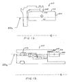
- Fig. 5 is a cross-sectional view of a primary ring assembly of a bellows mechanical seal embodying the features of the present invention.
- Fig. 5A is a cross-sectional view of an alternative primary ring and an alternative primary ring shell embodying the features of the present invention.
- Fig. 6 is an enlarged cross-sectional view of the primary ring and primary ring shell of the primary ring assembly of Fig. 5 .
- Fig. 7 is a cross-sectional free-body diagram of the primary ring assembly of Fig. 5 , showing contact pressure distribution under room temperature and no differential pressure on the primary ring by process/barrier liquid.
- Fig. 8 is a cross-sectional free-body diagram of the primary ring assembly of Fig. 5 , showing contact forces and contract pressure distribution under full operating temperature and external pressure applied by process/barrier liquid.
- Fig. 9 is a cross-sectional free-body diagram of the primary ring assembly of Fig. 5 , showing contact forces and contract pressure distribution under full operating temperature and internal pressure applied by process/barrier liquid.
- Fig. 10 is a cross-sectional view of the primary ring assembly of Fig. 5 used in conjunction with a conventional mating ring assembly.
- Fig. 11 is a cross-sectional view of the primary ring assembly of Fig. 5 used in conjunction with a mating ring assembly embodying the features of the present invention.
- Fig. 12 is a cros-sectional view of an alternative primary ring assembly, which does not form part of the present-invention, with a symmetrical, unbalanced primary ring.
- Fig. 13 is a cross-sectional view of an alternative primary ring assembly, which does not form part of the present invention, with a symmetrical, balanced primary ring.
- Alloy-718 metallurgy which is resistant to the corrosive attack even at high temperature.
- heat-treated Alloy-718 retains its inherent strength much better at high temperatures, e.g. 427°C (800 °F) or higher.
- Alloy-42 not only has a much lower relative strength at room temperature to start with, but also its strength drops considerably at higher temperatures.
- Alloy-718 is not only several times stronger than the Alloy-42 at room temperature, but also retains it high strength much better at higher temperature than Alloy-42. TABLE2 Temp °C (°F) Yield Strength (KSI) Alloy 718 Alloy 42 21(70) 125 40 538(1000) 90 14
- the mechanical seal design of the present invention provides highly enhanced face stability compared to prior art mechanical seal designs because it is thermally insensitive and maintains axially constant contract stresses in the shell/adapter, interference-fit region.
- the seal can adapt to a wide-range of temperature extremes found in applications such as pumps operating in high-temperature corrosive environments in refinery distillation units.
- This face stability as well as the structural integrity of the components is maintained even with a relatively high amount of the interference-fit between the shell and the primary ring.
- This high interference level is essential to accommodate vastly different thermal expansion coefficients of the shell and the seal ring materials, which are dictated by a demanding application, described above.
- Such exceptional face stability results in reduced leakage and potentially longer seal life.
- This seal can be designed with dual pressure capability, which can operate with higher-pressure process/barrier liquid either at the external or the internal location.
- the subject invention of the seal ring assembly can be either stationary attached to the housing, which is capable of handling high shaft speed applications and high shaft-to-seal chamber misalignment, or it can be mounted on the shaft, intended for applications where a dependable, high-strength rotating seal is preferred.
- Some typical operating limits are:
- FIGS 5 and 6 illustrate an embodiment or a primary ring assembly 10 embodying the present invention.
- the primary ring assembly 10 includes a primary ring shell 12, a primary ring 14 and bellows 16.
- a rotating shaft 18, centered about a longitudinal axis 20, extends through the primary ring assembly 10.
- axial and axially as used in describing the embodiments mean longitinually along the axis 20 of the shaft 18.
- the terms radial and radially as used in describing the embodiments mean in a plane generally perpendicular to the axis 20 of the shaft 18 toward and away from the axis.
- the primary ring 14 defines an axially extending annular outer surface 53 and a radially extending seal face 52.
- the annular outer surface 53 is a section of the outer surface of the primary ring 14 adapted for engagement with the shell 12, to be discussed further below. It should be noted that the annular outer surface 53 is not necessarily a radially outermost surface, as evidenced by the annular surface adjacent to the seal face 52 located more radially outward.
- the seal face 52 of the primary ring 52 is adapted for engagement with a corresponding seal face of a mating ring. Possible materials for construction of the primary ring 14 include carbon, impregnated carbon, tungsten carbide (WC), silicon carbide (SiC), silicon/carbon graphite composite, and bronze.
- the shell 12 is made up of two pieces - a front-piece 22 and a back-piece 24, which are welded together at their junction 26.
- Possible materials for construction of the primary ring shell pieces 22 and 24 include Alloy 718, Alloy 625, Alloy 620, Alloy 20, Hastelloy, AM 350, and stainless steel.
- the material for construction of primary ring shell pieces 22 and 24 is Alloy 718.
- the bellows 16 is welded to the back-piece shell 24 at their junction 28.
- the bellows 16 can be of single or multi-ply construction. Possible materials for construction of the bellows 16 include Alloy 718, Hastelloy, AM350, Alloy 20, and stainless steel.
- the material for construction of the bellows 16 is Alloy 718.
- this new design the subject of this current invention disclosure, will be referred to as the high temperature and corrosive application seal or "HTC" seal in short.
- This two-piece shell arrangement utilizes an optimized geometrical shape that may be quite intricate but can be machined into the front-piece 22.
- the ultimate goal has been to achieve optimum seal face stability over the operating temperature and pressure ranges having minimum amount of face coning in either direction, which is commonly known as "OD" or "ID high.”
- OD operating temperature and pressure ranges having minimum amount of face coning in either direction
- ID high minimum amount of face coning in either direction
- Such enhanced face stability results in reduced leakage and longer seal life.
- the enhanced, two-piece design can be used to attach a seal face to most traditional seal designs (i.e., pusher) with the similar performance benefits.
- the front-piece shell 22 is shown to have an engaging foot portion 30 into which the primary ring 14 is interference-fitted.
- the engaging foot portion 30 defines an axially extending engagement surface 32 for interference-fit engagement with annular surface 53 of the primary ring 14.
- the foot portion 30 has an inner foot portion 34, a middle foot portion 36, and an outer foot portion 38.
- the contact region of the engagement surface 32 at the back of the engaging foot portion is the heel 40 and its front part is the toe 42.
- the shin portion 48 extends radially from the foot portion 30.
- the shin portion 48 has an axial length L s that allows the shin portion to flex upon the primary ring 14 interference-fitted into the front piece shell 22.
- the inner foot portion 34 at its engagement surface, near the heal 40, has an axial length L h .
- the foot portion 30 at its engagement surface 32 has an axial length L f .
- the axial length L f of the foot portion 30 at its engagement surface is greater than the axial length L s of the shin portion.
- the ratio (L h /L f ) of inner foot portion length L h at its engagement surface to foot portion length L f at its engagement surface is greater than 0.5. More preferably, the ratio (L h /L f ) of inner foot portion length L h at its engagement surface to foot portion length L f at its engagement surface is between 0.556 and 0.625. It is important to distribute this contact pressure about the body center of rotation to achieve a near zero net moment on the primary seal. This is necessary to maintain face flatness as the application pressure and temperature change. Traditional shell designs, having an inner foot portion length to foot portion length at their engagement surfaces ratio closer to zero (0), do not have an evenly distributed contact pressure and exhibit difficulty controlling face flatness.
- the dimensions (e.g. lengths and thicknesses) of all these aforesaid regions described in the previous paragraphs, including the primary ring dimensions, are treated as parameters for the optimization process and are iteratively designed to get optimal performance characteristics.
- These control parameters allow for precise adjustment to control the interference contact pressure, the contact stress, and face stability for a variety of primary ring geometries over a wide range of operating temperatures and pressures or a specific set of temperatures and pressures.
- the optimized design is thermally insensitive and has an axially constant contact stress distribution in the interference-fit region.
- the control parameters: inner foot portion 34, outer foot portion 38, shin portion 48, hub portion 50 and thigh portion 44, can be adjusted in thickness and length to accommodate varying primary ring geometries.
- the interference-fitted design between the shell 12 and primary ring 14 eliminates the need of any secondary sealing components, such as flexible graphite disclosed in U.S. Patent 4,971,337 which may be problematic because its uneven surface is in contact with the shell back, the signature of which may be partially transmitted to the seal face.
- the front-piece shell 22 is joined to the back-piece shell 24 after the initial interference-fitting of the front piece shell 22 with the primary ring 14. This process eliminates bending stresses and moments in the area of the hinge that are present in the traditional one-piece arrangements, such as the seal assembly shown in Figure 1 .
- the nominal interference diameter D s which is also called the sealing diameter, is designed to be very close to the Mean Effective Diameter ED z of the bellows as shown in Figure 5 .
- the Effective Diameter or "ED" of a bellows is a fictitious diameter up to which the applied pressure effectively penetrates to exert a closing force on the seal. This is akin to the "balance diameter" of a pusher-type seal.
- the Mean Effective Diameter is a theoretical effective diameter at zero differential pressure applied on the seal ring 14, which is taken to be the arithmetic mean of the bellows core outside, and inside diameters.
- the seal face 52 of the primary ring 14 is designed so that the Mean Effective Diameter position gives rise to an initial balance at zero differential pressure in which the radial centerline of the seal face 52 is near the Mean Effective Diameter ED Z as shown in Figure 5 .
- the primary ring 14 of this particular embodiment is asymmetrical and balanced.
- This primary ring 14 is considered asymmetrical because the two sides of the primary ring 14 located axially from its center of gravity CG are not symmetrical.
- This primary ring is considered balanced because the radial centerline of the seal face 52 is located near the effective diameter ED Z of the bellows 16 at zero differential pressure.
- Figure 8 shows the external pressure acting on the primary ring 14. As seen, while the full external pressure acts on the overhung portion of the primary ring 14 outside the engaging foot portion 30 of the shell 12, on the face 52, however, the pressure decreases to a zero differential level at the ID. Although the face pressure profile is shown to be linear, which is the case with a parallel seal interface, in actuality, it could be curved inward or outward, depending on the operating face coning.
- the net axial force acting on the primary ring is tending to cause axial slippage between the primary ring 14 and the shell 12 at the contact region and push the primary ring 14 towards the back-piece shell 24.
- the mating ring face not shown in the Figure 8 , tends to cause rotational slippage at the contact region due to the face contact load and the corresponding interface friction.
- the net axial slippage force can be shown to be approximately equal to the external pressure times the annular area between the sealing diameter (or nominal interference diameter) and the effective diameter at full external pressure plus the initial bellows spring load.
- the level of the initial interference between the shell 12 and the primary ring 14 is chosen in such a way that at the full external pressure and the maximum operating temperature, the average contact pressure level is more than adequate to resist primary ring slippage in the axial as well as the rotational direction.
- the interference diameter D s is within plus and minus 10% (+10% and -10%) of the effective diameter ED z of the bellows at zero differential pressure. More preferably, the interference diameter D s is within +6% and - 6% of the effective diameter ED z of the bellows at zero pressure. It is important to minimize the hydraulic forces acting in an axial direction to move the primary seal relative to the shell. As these forces increase, the amount of contact force provided by the interference fit must be increased to prevent movement.
- the effective diameter does vary with system pressure.
- the net axial force on the primary ring 14 that is tending to cause axial slippage is approximately equal to the internal pressure times the annular area between the effective diameter and the sealing diameter plus the initial bellows spring load.
- the initial interference level is so chosen that average contact pressure magnitude at the full internal pressure and the maximum operating temperature is more than adequate to resist any primary ring slippage.
- this design is capable of handling either external or internal pressure applications with a single bellows, whereas some prior designs required two different size bellows to achieve the same task. Many successful tests have been done in the laboratory to confirm this capability.
- Figure 5 shows one viable configuration of the front-piece shell, there are other embodiments that can be specialized from this general shape. These shapes include, but are not limited to, the inner foot portion 34 being shorter and/or thicker than the outer foot portion 38, the shin portion 48 shorter and/or thicker than what is shown, absence of the hub portion 50, absence of either inner foot portion 34 or outer foot portion 38, and the like.
- FIGS 5 and 6 two possible primary ring nose configurations are shown in Figures 5 and 6 , one having a blunt nose 54 as shown in Figure 5 and the other having a step nose 56 as shown in Figure 6 .
- the blunt-nose 54 configuration is typically used with the hard primary ring materials e.g. silicon and tungsten carbides, whereas the step-nose 56 configuration is typically used with the softer materials like carbon.
- Figures 5 and 6 show two possible configurations of the back-piece shell 24. In the conventional configuration as shown in Figure 5 , this back-piece shell 24 inside diameter (ID) is extended low at 58 towards the inside diameter of primary ring 14. In the second configuration as shown in Figure 6 , the back-piece shell 24 is truncated at 60 to have a higher ID.
- ID inside diameter
- the primary ring 14 is first interference-fitted into the front-piece shell 22 that is then welded to the back-piece shell 24 and the bellows 16.
- the shape of the front-piece shell 22 has been optimized in such a way that the extent of the contact region between its engaging foot portion 30 and the primary ring 14 is almost 100%, extending from its heel 40 to the toe 42, as illustrated by the contact pressure distribution PD Z in Figure 7 .
- a conventionally interference-fitted primary-ring assembly 510 will have a relatively concentrated contact near the heel 540, extending over about 20% of the corresponding foot portion length as illustrated in Figure 2 . Consequently, the maximum contact pressure of the HTC design as shown in Figure 7 is several times lower than that of a conventional design for the same level of interference shown in Figure 2 .
- the primary ring 14 is positioned at an optimum depth with respect to the shell foot portion 30 so as to have a near-zero net moment about its center of gravity/rotation due to the above contact pressure distribution PD Z .
- This situation would leave the seal face 52 to remain almost flat without any perceptible coning.
- This analytical finding has been repeatedly verified in the laboratory. This means that the optimally positioned primary ring, which is at a "stress-free state” before the interference-fitting operation, will remain free of any net twisting moment due to the contact pressure at its "fully stressed state” after the interference-fitting operation. Consequently, the primary ring seal face 52, which is initially lapped flat, will remain flat after interference-fitting into the front-piece shell at the optimum position. This is an unprecedented behavior, not observed with a traditionally interference-fitted seal design.
- FIG. 8 shows a representative contact pressure distribution PD OD , with the contact extending over about 70% of the foot portion length. This extent of contact is much larger than that with a conventional prior art primary ring assembly 510 for which it is about 15% under similar circumstances as shown in Figure 3 .
- Such relatively larger contact support inherently gives rise to higher relative face stability as the primary ring 14 is inhibited from rotation due to any unbalanced net moment caused by the pressure application.
- the front-piece shell 22 and the primary ring 14 are designed in such a way to obtain near zero nominal face deflection when the primary ring 14 is interference-fitted into the shell 12 so that the face flatness would change very little (e.g. a few Helium light bands) with temperature up to the operating temperature and any of its excursions.
- the design is further optimized so that face-coning magnitudes due to the external and internal pressure conditions are not only minimized but also quite equal in magnitude so that a symmetric behavior is achieved with the directions of pressure application.
- the face coning is in the "OD high” direction whereas with the internal pressure, it is in the "ID high” direction.
- the magnitudes of the face coning for the external and the internal pressures are not only made almost equal through the optimization process, but also these values are appreciably less than those for a conventional interference-fitted seal. It may be noted that high face coning can be responsible for higher leakage as well as accelerated face wear.
- the seal design embodying the present invention provides full or nearly full contact over the interference-fit region leads to highly enhanced face stability with operating temperature and pressure in comparison with a conventional interference-fitted seal. Furthermore, because of an extended contact length and relatively uniform contact pressure distribution, much higher level of interference is possible between the shell and the primary ring without unduly stressing the primary ring locally and causing its breakage.
- the primary ring assembly 10 of the present invention can have a mating ring assembly 70A of a conventional design, as shown in Figure 10 or a mating ring assembly 70B, incorporating the HTC seal principles of the present invention, as shown in Figure 11 .
- the mating ring assembly 70B includes a mating ring shell 72 and a mating ring 74.
- Possible materials for construction of the mating ring 74 include carbon, impregnated carbon, tungsten carbide, silicon carbide, silicon/carbon graphite composite, and bronze.
- the mating ring shell 72 is made up of two pieces - a front-piece 76 and a back piece 78, which are welded together at their junction 80.
- Possible materials for construction of the mating ring shell pieces 76 and 78 include Alloy 718, Alloy 625, Alloy 620, Alloy 20, Hastelloy, AM 350, and stainless steel.
- the material for construction of mating ring shell pieces 76 and 78 is Alloy 718.
- the front-piece 76 of the mating ring shell 72 has an engaging foot portion 82 into which the mating ring 74 is interference-fitted.
- the engaging foot portion 82 of the mating ring shell 72 defines an engagement surface 84 for interference-fit engagement with the mating ring 74.
- the foot portion 82 has an inner foot portion 86, a middle foot portion 88, and an outer foot portion 90.
- the contact region of the engaging surface 84 at the back of the engaging foot portion is the heel 92 and its front part is the toe 94.
- the dimensions (e.g. lengths and thicknesses) of all these aforesaid regions described in the previous paragraphs, including the mating ring dimensions, are treated as parameters for the optimization process.
- the location of the mating ring with respect to the foot portion is also an optimization parameter.
- Figure 12 illustrates an alternative primary ring assembly 210 which does not form part of the present invention.
- the primary ring 214 is symmetrical and unbalanced. This primary ring is considered symmetrical because the two sides of the primary ring 214 located axially from its center of gravity CG are essentially symmetrical. This primary ring is considered unbalance because the radial centerline of the seal face 252 is not located near the effective diameter ED z of the bellows at zero differential pressure.
- the shape of the shin portion 248 and the foot portion 230 of the shell 212 is different than the shape of the shin portion 48 and the foot portion 30 of the primary ring assembly 10 illustrated in Figure 5 .
- Figure 13 illustrates a second alternative primary ring assembly 310 which does not form part of the present invention.
- the primary ring 314 is symmetrical and balanced. This primary ring is considered symmetrical because the two sides of the primary ring 314 located axially from its center of gravity CG are essentially symmetrical. This primary ring is considered balance because the radial centerline of the seal face 352 is located near the effect diameter ED z of the O-ring 316 at zero differential pressure.
- the shape of the shin portion 348 and foot portion 330 of the shell 312 is different than the shape of the shin portions 48 and 248 and foot portions 30 and 230 of the primary ring assemblies 10 and 210 illustrated in Figures 5 and 12 .
- the optimal geometric dimensions of the shin portion and foot portion vary due to the shape of the primary ring and the radial centerline of the seal face relative to the effective diameter ED Z of the bellows/O-ring at zero differential pressure.
Landscapes
- Engineering & Computer Science (AREA)
- General Engineering & Computer Science (AREA)
- Mechanical Engineering (AREA)
- Mechanical Sealing (AREA)
- Gasket Seals (AREA)
Priority Applications (1)
| Application Number | Priority Date | Filing Date | Title |
|---|---|---|---|
| PL07758154T PL1996839T3 (pl) | 2006-03-08 | 2007-03-08 | Uszczelnienie mechaniczne o podwyższonej stabilności powierzchni czołowej |
Applications Claiming Priority (3)
| Application Number | Priority Date | Filing Date | Title |
|---|---|---|---|
| US78033406P | 2006-03-08 | 2006-03-08 | |
| US11/683,202 US7959156B2 (en) | 2006-03-08 | 2007-03-07 | Mechanical seal with enhanced face stability |
| PCT/US2007/063576 WO2007104014A2 (en) | 2006-03-08 | 2007-03-08 | Mechanical seal with enhanced face stability |
Publications (2)
| Publication Number | Publication Date |
|---|---|
| EP1996839A2 EP1996839A2 (en) | 2008-12-03 |
| EP1996839B1 true EP1996839B1 (en) | 2012-12-26 |
Family
ID=38475858
Family Applications (1)
| Application Number | Title | Priority Date | Filing Date |
|---|---|---|---|
| EP07758154A Active EP1996839B1 (en) | 2006-03-08 | 2007-03-08 | Mechanical seal with enhanced face stability |
Country Status (9)
| Country | Link |
|---|---|
| US (1) | US7959156B2 (zh) |
| EP (1) | EP1996839B1 (zh) |
| CN (1) | CN101400926B (zh) |
| BR (2) | BR122019022399B1 (zh) |
| CA (1) | CA2645048C (zh) |
| ES (1) | ES2399068T3 (zh) |
| MX (1) | MX2008011273A (zh) |
| PL (1) | PL1996839T3 (zh) |
| WO (1) | WO2007104014A2 (zh) |
Families Citing this family (10)
| Publication number | Priority date | Publication date | Assignee | Title |
|---|---|---|---|---|
| US9568108B2 (en) * | 2009-03-30 | 2017-02-14 | Eagle Industry Co., Ltd. | Bellows type mechanical seal |
| EP2416037B1 (en) * | 2009-03-30 | 2013-09-04 | Eagle Industry Co., Ltd. | Bellows type mechanical seal |
| US20140265146A1 (en) * | 2013-03-15 | 2014-09-18 | Eaton Corporation | Composite dynamic seal mating ring or rotor |
| CN104791488B (zh) * | 2015-02-14 | 2018-01-23 | 江苏科奥流体科技有限公司 | 石油化工用波纹管机械密封结构 |
| EP3259505B1 (en) * | 2015-02-18 | 2021-09-29 | Eaton Intelligent Power Limited | Blow-out resistant seal and assembly |
| JP6823602B2 (ja) * | 2015-11-09 | 2021-02-03 | イーグル工業株式会社 | メカニカルシール |
| GB201702893D0 (en) * | 2017-02-23 | 2017-04-12 | Aes Eng Ltd | Mechanical seal |
| US11333253B2 (en) * | 2018-12-19 | 2022-05-17 | Pratt & Whitney Canada Corp. | Magnetic seal assembly |
| US11815182B2 (en) * | 2019-05-23 | 2023-11-14 | EagleBurgmann Japan Co., Ltd. | Mechanical seal |
| GB2593782B (en) * | 2020-04-03 | 2022-04-13 | Crane John Inc | Non-contacting seal including an interference fit seal ring |
Family Cites Families (20)
| Publication number | Priority date | Publication date | Assignee | Title |
|---|---|---|---|---|
| US2941825A (en) * | 1954-11-26 | 1960-06-21 | Heinrich Adeline | Sealing system for bearings, shafts, etc. |
| US3131941A (en) * | 1960-11-21 | 1964-05-05 | Donley Products Inc | Sealing unit |
| US3560004A (en) * | 1969-03-24 | 1971-02-02 | Ernest F Donley Sons Inc | Shaft seal having passage for heat-transfer fluid |
| US3765689A (en) * | 1971-09-27 | 1973-10-16 | Durametallic Corp | Mechanical seal construction |
| IT1084994B (it) * | 1976-06-09 | 1985-05-28 | Funk Heporaut Kirsti | Guarnizione per alberi,in particolare in mulini con agiotatore oppure in mulini colloidali |
| US4335888A (en) * | 1978-03-20 | 1982-06-22 | Nippon Pillar Packing Co. Ltd. | Mechanical seal |
| US4261581A (en) * | 1980-04-14 | 1981-04-14 | Durametallic Corporation | Mechanical seal with improved face ring mounting |
| US4364571A (en) * | 1980-10-09 | 1982-12-21 | Durametallic Corporation | Tapered seal seat between stationary insert and gland |
| US4365816A (en) * | 1980-10-29 | 1982-12-28 | Eg&G Sealol, Inc. | Self-damping bellows seal assembly |
| GB2208412B (en) * | 1987-06-05 | 1991-01-23 | Eg & G Ltd | Bellows seal arrangement |
| US4744569A (en) * | 1987-10-13 | 1988-05-17 | Bw/Ip International, Inc. | Bellows mechanical seal with inactive diaphragms |
| US4971337A (en) * | 1988-05-26 | 1990-11-20 | Bw/Ip International, Inc. | Mechanical seal assembly |
| US5042824A (en) * | 1990-02-08 | 1991-08-27 | Eg&G Sealol, Inc. | Balanced shrink fit seal ring assembly |
| US5901965A (en) * | 1996-03-01 | 1999-05-11 | Ringer; Yoram | Bellows seal having balanced, de-coupled seal ring and seal ring shell |
| US5954341A (en) * | 1996-07-30 | 1999-09-21 | John Crane Sealol Inc. | Bellows seal with drive collar for reverse pressure capability |
| US6113106A (en) * | 1997-11-03 | 2000-09-05 | Freudenberg-Nok General Partnership | Gimballed mechanical face seal |
| DE29805089U1 (de) * | 1998-03-20 | 1998-06-10 | Burgmann Dichtungswerk Feodor | Gleitringdichtungsanordnung |
| US6299173B1 (en) * | 1998-10-16 | 2001-10-09 | John Crane Inc. | Mechanical end face seal ring having a compliant seal face |
| US6464231B2 (en) * | 2000-12-20 | 2002-10-15 | Flowserve Management Company | Bellows seal with spring-loaded radial secondary seal |
| CN100370167C (zh) * | 2001-11-22 | 2008-02-20 | 三菱化学株式会社 | 传输可聚合液体的方法和传输设备 |
-
2007
- 2007-03-07 US US11/683,202 patent/US7959156B2/en active Active
- 2007-03-08 CA CA2645048A patent/CA2645048C/en active Active
- 2007-03-08 EP EP07758154A patent/EP1996839B1/en active Active
- 2007-03-08 MX MX2008011273A patent/MX2008011273A/es active IP Right Grant
- 2007-03-08 ES ES07758154T patent/ES2399068T3/es active Active
- 2007-03-08 PL PL07758154T patent/PL1996839T3/pl unknown
- 2007-03-08 WO PCT/US2007/063576 patent/WO2007104014A2/en active Application Filing
- 2007-03-08 BR BR122019022399-8A patent/BR122019022399B1/pt active IP Right Grant
- 2007-03-08 CN CN200780008271XA patent/CN101400926B/zh not_active Expired - Fee Related
- 2007-03-08 BR BRPI0708582-6A patent/BRPI0708582B1/pt active IP Right Grant
Also Published As
| Publication number | Publication date |
|---|---|
| WO2007104014A2 (en) | 2007-09-13 |
| CN101400926A (zh) | 2009-04-01 |
| US7959156B2 (en) | 2011-06-14 |
| CA2645048A1 (en) | 2007-09-13 |
| ES2399068T3 (es) | 2013-03-25 |
| US20070210526A1 (en) | 2007-09-13 |
| CA2645048C (en) | 2015-10-13 |
| BRPI0708582A2 (pt) | 2011-06-07 |
| CN101400926B (zh) | 2013-01-02 |
| BRPI0708582B1 (pt) | 2020-10-13 |
| MX2008011273A (es) | 2008-11-28 |
| EP1996839A2 (en) | 2008-12-03 |
| PL1996839T3 (pl) | 2013-05-31 |
| BR122019022399B1 (pt) | 2021-01-05 |
| WO2007104014A3 (en) | 2008-10-02 |
Similar Documents
| Publication | Publication Date | Title |
|---|---|---|
| EP1996839B1 (en) | Mechanical seal with enhanced face stability | |
| EP2324209B1 (en) | Intershaft seal system | |
| JP2526024B2 (ja) | 追従シ―ル具 | |
| US8240672B2 (en) | Low breakout friction energized gasket | |
| EP2916048B1 (en) | Seal assembly | |
| US9568108B2 (en) | Bellows type mechanical seal | |
| US6299173B1 (en) | Mechanical end face seal ring having a compliant seal face | |
| US5505466A (en) | Cylinder head gasket with retaining ring and spring seal | |
| EP2416037B1 (en) | Bellows type mechanical seal | |
| US20230151887A1 (en) | Non-contacting seal including an interference fit seal ring | |
| US4948151A (en) | Rotary end face seal assembly | |
| US8261767B1 (en) | Powdered metal inlay | |
| US11346448B2 (en) | Carbon seal assembly | |
| US5006043A (en) | Floating annular seal with thermal compensation | |
| EP3130759B1 (en) | Gas turbine membrane seal | |
| JPS6162670A (ja) | メカニカルシ−ル |
Legal Events
| Date | Code | Title | Description |
|---|---|---|---|
| PUAI | Public reference made under article 153(3) epc to a published international application that has entered the european phase |
Free format text: ORIGINAL CODE: 0009012 |
|
| 17P | Request for examination filed |
Effective date: 20081002 |
|
| AK | Designated contracting states |
Kind code of ref document: A2 Designated state(s): AT BE BG CH CY CZ DE DK EE ES FI FR GB GR HU IE IS IT LI LT LU LV MC MT NL PL PT RO SE SI SK TR |
|
| AX | Request for extension of the european patent |
Extension state: AL BA HR MK RS |
|
| 17Q | First examination report despatched |
Effective date: 20100503 |
|
| GRAP | Despatch of communication of intention to grant a patent |
Free format text: ORIGINAL CODE: EPIDOSNIGR1 |
|
| DAX | Request for extension of the european patent (deleted) | ||
| GRAS | Grant fee paid |
Free format text: ORIGINAL CODE: EPIDOSNIGR3 |
|
| GRAA | (expected) grant |
Free format text: ORIGINAL CODE: 0009210 |
|
| AK | Designated contracting states |
Kind code of ref document: B1 Designated state(s): AT BE BG CH CY CZ DE DK EE ES FI FR GB GR HU IE IS IT LI LT LU LV MC MT NL PL PT RO SE SI SK TR |
|
| REG | Reference to a national code |
Ref country code: GB Ref legal event code: FG4D |
|
| REG | Reference to a national code |
Ref country code: CH Ref legal event code: EP |
|
| REG | Reference to a national code |
Ref country code: AT Ref legal event code: REF Ref document number: 590670 Country of ref document: AT Kind code of ref document: T Effective date: 20130115 |
|
| REG | Reference to a national code |
Ref country code: SE Ref legal event code: TRGR |
|
| REG | Reference to a national code |
Ref country code: NL Ref legal event code: T3 |
|
| REG | Reference to a national code |
Ref country code: DE Ref legal event code: R096 Ref document number: 602007027646 Country of ref document: DE Effective date: 20130307 |
|
| REG | Reference to a national code |
Ref country code: ES Ref legal event code: FG2A Ref document number: 2399068 Country of ref document: ES Kind code of ref document: T3 Effective date: 20130325 |
|
| PG25 | Lapsed in a contracting state [announced via postgrant information from national office to epo] |
Ref country code: LT Free format text: LAPSE BECAUSE OF FAILURE TO SUBMIT A TRANSLATION OF THE DESCRIPTION OR TO PAY THE FEE WITHIN THE PRESCRIBED TIME-LIMIT Effective date: 20121226 |
|
| REG | Reference to a national code |
Ref country code: AT Ref legal event code: MK05 Ref document number: 590670 Country of ref document: AT Kind code of ref document: T Effective date: 20121226 |
|
| REG | Reference to a national code |
Ref country code: LT Ref legal event code: MG4D |
|
| PG25 | Lapsed in a contracting state [announced via postgrant information from national office to epo] |
Ref country code: SI Free format text: LAPSE BECAUSE OF FAILURE TO SUBMIT A TRANSLATION OF THE DESCRIPTION OR TO PAY THE FEE WITHIN THE PRESCRIBED TIME-LIMIT Effective date: 20121226 Ref country code: GR Free format text: LAPSE BECAUSE OF FAILURE TO SUBMIT A TRANSLATION OF THE DESCRIPTION OR TO PAY THE FEE WITHIN THE PRESCRIBED TIME-LIMIT Effective date: 20130327 Ref country code: LV Free format text: LAPSE BECAUSE OF FAILURE TO SUBMIT A TRANSLATION OF THE DESCRIPTION OR TO PAY THE FEE WITHIN THE PRESCRIBED TIME-LIMIT Effective date: 20121226 |
|
| REG | Reference to a national code |
Ref country code: PL Ref legal event code: T3 |
|
| PG25 | Lapsed in a contracting state [announced via postgrant information from national office to epo] |
Ref country code: CY Free format text: LAPSE BECAUSE OF FAILURE TO SUBMIT A TRANSLATION OF THE DESCRIPTION OR TO PAY THE FEE WITHIN THE PRESCRIBED TIME-LIMIT Effective date: 20121226 Ref country code: BE Free format text: LAPSE BECAUSE OF FAILURE TO SUBMIT A TRANSLATION OF THE DESCRIPTION OR TO PAY THE FEE WITHIN THE PRESCRIBED TIME-LIMIT Effective date: 20121226 Ref country code: EE Free format text: LAPSE BECAUSE OF FAILURE TO SUBMIT A TRANSLATION OF THE DESCRIPTION OR TO PAY THE FEE WITHIN THE PRESCRIBED TIME-LIMIT Effective date: 20121226 Ref country code: BG Free format text: LAPSE BECAUSE OF FAILURE TO SUBMIT A TRANSLATION OF THE DESCRIPTION OR TO PAY THE FEE WITHIN THE PRESCRIBED TIME-LIMIT Effective date: 20130326 Ref country code: IS Free format text: LAPSE BECAUSE OF FAILURE TO SUBMIT A TRANSLATION OF THE DESCRIPTION OR TO PAY THE FEE WITHIN THE PRESCRIBED TIME-LIMIT Effective date: 20130426 Ref country code: SK Free format text: LAPSE BECAUSE OF FAILURE TO SUBMIT A TRANSLATION OF THE DESCRIPTION OR TO PAY THE FEE WITHIN THE PRESCRIBED TIME-LIMIT Effective date: 20121226 Ref country code: AT Free format text: LAPSE BECAUSE OF FAILURE TO SUBMIT A TRANSLATION OF THE DESCRIPTION OR TO PAY THE FEE WITHIN THE PRESCRIBED TIME-LIMIT Effective date: 20121226 |
|
| PG25 | Lapsed in a contracting state [announced via postgrant information from national office to epo] |
Ref country code: RO Free format text: LAPSE BECAUSE OF FAILURE TO SUBMIT A TRANSLATION OF THE DESCRIPTION OR TO PAY THE FEE WITHIN THE PRESCRIBED TIME-LIMIT Effective date: 20121226 Ref country code: PT Free format text: LAPSE BECAUSE OF FAILURE TO SUBMIT A TRANSLATION OF THE DESCRIPTION OR TO PAY THE FEE WITHIN THE PRESCRIBED TIME-LIMIT Effective date: 20130426 |
|
| PG25 | Lapsed in a contracting state [announced via postgrant information from national office to epo] |
Ref country code: DK Free format text: LAPSE BECAUSE OF FAILURE TO SUBMIT A TRANSLATION OF THE DESCRIPTION OR TO PAY THE FEE WITHIN THE PRESCRIBED TIME-LIMIT Effective date: 20121226 Ref country code: MC Free format text: LAPSE BECAUSE OF NON-PAYMENT OF DUE FEES Effective date: 20130331 |
|
| REG | Reference to a national code |
Ref country code: CH Ref legal event code: PL |
|
| PLBE | No opposition filed within time limit |
Free format text: ORIGINAL CODE: 0009261 |
|
| STAA | Information on the status of an ep patent application or granted ep patent |
Free format text: STATUS: NO OPPOSITION FILED WITHIN TIME LIMIT |
|
| 26N | No opposition filed |
Effective date: 20130927 |
|
| REG | Reference to a national code |
Ref country code: IE Ref legal event code: MM4A |
|
| REG | Reference to a national code |
Ref country code: DE Ref legal event code: R097 Ref document number: 602007027646 Country of ref document: DE Effective date: 20130927 |
|
| PG25 | Lapsed in a contracting state [announced via postgrant information from national office to epo] |
Ref country code: IE Free format text: LAPSE BECAUSE OF NON-PAYMENT OF DUE FEES Effective date: 20130308 Ref country code: CH Free format text: LAPSE BECAUSE OF NON-PAYMENT OF DUE FEES Effective date: 20130331 Ref country code: LI Free format text: LAPSE BECAUSE OF NON-PAYMENT OF DUE FEES Effective date: 20130331 |
|
| PG25 | Lapsed in a contracting state [announced via postgrant information from national office to epo] |
Ref country code: MT Free format text: LAPSE BECAUSE OF FAILURE TO SUBMIT A TRANSLATION OF THE DESCRIPTION OR TO PAY THE FEE WITHIN THE PRESCRIBED TIME-LIMIT Effective date: 20121226 |
|
| REG | Reference to a national code |
Ref country code: DE Ref legal event code: R082 Ref document number: 602007027646 Country of ref document: DE Representative=s name: FRIESE GOEDEN PATENTANWAELTE PARTGMBB, DE Ref country code: DE Ref legal event code: R082 Ref document number: 602007027646 Country of ref document: DE Representative=s name: ANDRAE WESTENDORP PATENTANWAELTE PARTNERSCHAFT, DE |
|
| PG25 | Lapsed in a contracting state [announced via postgrant information from national office to epo] |
Ref country code: TR Free format text: LAPSE BECAUSE OF FAILURE TO SUBMIT A TRANSLATION OF THE DESCRIPTION OR TO PAY THE FEE WITHIN THE PRESCRIBED TIME-LIMIT Effective date: 20121226 |
|
| PG25 | Lapsed in a contracting state [announced via postgrant information from national office to epo] |
Ref country code: LU Free format text: LAPSE BECAUSE OF NON-PAYMENT OF DUE FEES Effective date: 20130308 Ref country code: HU Free format text: LAPSE BECAUSE OF FAILURE TO SUBMIT A TRANSLATION OF THE DESCRIPTION OR TO PAY THE FEE WITHIN THE PRESCRIBED TIME-LIMIT; INVALID AB INITIO Effective date: 20070308 |
|
| REG | Reference to a national code |
Ref country code: FR Ref legal event code: PLFP Year of fee payment: 10 |
|
| PGFP | Annual fee paid to national office [announced via postgrant information from national office to epo] |
Ref country code: PL Payment date: 20151216 Year of fee payment: 10 |
|
| PGFP | Annual fee paid to national office [announced via postgrant information from national office to epo] |
Ref country code: ES Payment date: 20160211 Year of fee payment: 10 Ref country code: CZ Payment date: 20160211 Year of fee payment: 10 |
|
| PGFP | Annual fee paid to national office [announced via postgrant information from national office to epo] |
Ref country code: SE Payment date: 20160311 Year of fee payment: 10 Ref country code: FI Payment date: 20160309 Year of fee payment: 10 |
|
| REG | Reference to a national code |
Ref country code: DE Ref legal event code: R082 Ref document number: 602007027646 Country of ref document: DE Representative=s name: MATHYS & SQUIRE EUROPE PATENTANWAELTE PARTNERS, DE Ref country code: DE Ref legal event code: R082 Ref document number: 602007027646 Country of ref document: DE Representative=s name: FRIESE GOEDEN PATENTANWAELTE PARTGMBB, DE |
|
| REG | Reference to a national code |
Ref country code: FR Ref legal event code: PLFP Year of fee payment: 11 |
|
| PG25 | Lapsed in a contracting state [announced via postgrant information from national office to epo] |
Ref country code: FI Free format text: LAPSE BECAUSE OF NON-PAYMENT OF DUE FEES Effective date: 20170308 Ref country code: CZ Free format text: LAPSE BECAUSE OF NON-PAYMENT OF DUE FEES Effective date: 20170308 |
|
| REG | Reference to a national code |
Ref country code: SE Ref legal event code: EUG |
|
| PG25 | Lapsed in a contracting state [announced via postgrant information from national office to epo] |
Ref country code: SE Free format text: LAPSE BECAUSE OF NON-PAYMENT OF DUE FEES Effective date: 20170309 |
|
| REG | Reference to a national code |
Ref country code: FR Ref legal event code: PLFP Year of fee payment: 12 |
|
| REG | Reference to a national code |
Ref country code: ES Ref legal event code: FD2A Effective date: 20180705 |
|
| PG25 | Lapsed in a contracting state [announced via postgrant information from national office to epo] |
Ref country code: ES Free format text: LAPSE BECAUSE OF NON-PAYMENT OF DUE FEES Effective date: 20170309 |
|
| PG25 | Lapsed in a contracting state [announced via postgrant information from national office to epo] |
Ref country code: PL Free format text: LAPSE BECAUSE OF NON-PAYMENT OF DUE FEES Effective date: 20170308 |
|
| REG | Reference to a national code |
Ref country code: DE Ref legal event code: R082 Ref document number: 602007027646 Country of ref document: DE Representative=s name: MATHYS & SQUIRE EUROPE PATENTANWAELTE PARTNERS, DE |
|
| PGFP | Annual fee paid to national office [announced via postgrant information from national office to epo] |
Ref country code: IT Payment date: 20230213 Year of fee payment: 17 |
|
| P01 | Opt-out of the competence of the unified patent court (upc) registered |
Effective date: 20230522 |
|
| PGFP | Annual fee paid to national office [announced via postgrant information from national office to epo] |
Ref country code: FR Payment date: 20231229 Year of fee payment: 18 |
|
| PGFP | Annual fee paid to national office [announced via postgrant information from national office to epo] |
Ref country code: NL Payment date: 20240108 Year of fee payment: 18 |
|
| PGFP | Annual fee paid to national office [announced via postgrant information from national office to epo] |
Ref country code: DE Payment date: 20231229 Year of fee payment: 18 Ref country code: GB Payment date: 20240108 Year of fee payment: 18 |