EP1996518B1 - Appareil de filtration et de désinfection d'eau de mer/de ballast de navire et procédé s'y rapportant - Google Patents
Appareil de filtration et de désinfection d'eau de mer/de ballast de navire et procédé s'y rapportant Download PDFInfo
- Publication number
- EP1996518B1 EP1996518B1 EP07736574A EP07736574A EP1996518B1 EP 1996518 B1 EP1996518 B1 EP 1996518B1 EP 07736574 A EP07736574 A EP 07736574A EP 07736574 A EP07736574 A EP 07736574A EP 1996518 B1 EP1996518 B1 EP 1996518B1
- Authority
- EP
- European Patent Office
- Prior art keywords
- water
- cavitation
- chamber
- ballast
- ship
- Prior art date
- Legal status (The legal status is an assumption and is not a legal conclusion. Google has not performed a legal analysis and makes no representation as to the accuracy of the status listed.)
- Not-in-force
Links
Images

Classifications
-
- B—PERFORMING OPERATIONS; TRANSPORTING
- B63—SHIPS OR OTHER WATERBORNE VESSELS; RELATED EQUIPMENT
- B63J—AUXILIARIES ON VESSELS
- B63J4/00—Arrangements of installations for treating ballast water, waste water, sewage, sludge, or refuse, or for preventing environmental pollution not otherwise provided for
- B63J4/002—Arrangements of installations for treating ballast water, waste water, sewage, sludge, or refuse, or for preventing environmental pollution not otherwise provided for for treating ballast water
-
- B—PERFORMING OPERATIONS; TRANSPORTING
- B63—SHIPS OR OTHER WATERBORNE VESSELS; RELATED EQUIPMENT
- B63J—AUXILIARIES ON VESSELS
- B63J1/00—Arrangements of installations for producing fresh water, e.g. by evaporation and condensation of sea water
-
- C—CHEMISTRY; METALLURGY
- C02—TREATMENT OF WATER, WASTE WATER, SEWAGE, OR SLUDGE
- C02F—TREATMENT OF WATER, WASTE WATER, SEWAGE, OR SLUDGE
- C02F1/00—Treatment of water, waste water, or sewage
- C02F1/006—Water distributors either inside a treatment tank or directing the water to several treatment tanks; Water treatment plants incorporating these distributors, with or without chemical or biological tanks
-
- C—CHEMISTRY; METALLURGY
- C02—TREATMENT OF WATER, WASTE WATER, SEWAGE, OR SLUDGE
- C02F—TREATMENT OF WATER, WASTE WATER, SEWAGE, OR SLUDGE
- C02F1/00—Treatment of water, waste water, or sewage
- C02F1/34—Treatment of water, waste water, or sewage with mechanical oscillations
- C02F1/36—Treatment of water, waste water, or sewage with mechanical oscillations ultrasonic vibrations
-
- C—CHEMISTRY; METALLURGY
- C02—TREATMENT OF WATER, WASTE WATER, SEWAGE, OR SLUDGE
- C02F—TREATMENT OF WATER, WASTE WATER, SEWAGE, OR SLUDGE
- C02F2103/00—Nature of the water, waste water, sewage or sludge to be treated
- C02F2103/008—Originating from marine vessels, ships and boats, e.g. bilge water or ballast water
-
- C—CHEMISTRY; METALLURGY
- C02—TREATMENT OF WATER, WASTE WATER, SEWAGE, OR SLUDGE
- C02F—TREATMENT OF WATER, WASTE WATER, SEWAGE, OR SLUDGE
- C02F2301/00—General aspects of water treatment
- C02F2301/02—Fluid flow conditions
- C02F2301/024—Turbulent
-
- C—CHEMISTRY; METALLURGY
- C02—TREATMENT OF WATER, WASTE WATER, SEWAGE, OR SLUDGE
- C02F—TREATMENT OF WATER, WASTE WATER, SEWAGE, OR SLUDGE
- C02F2301/00—General aspects of water treatment
- C02F2301/02—Fluid flow conditions
- C02F2301/026—Spiral, helicoidal, radial
Definitions
- the present invention relates to an apparatus for filtration and disinfection of sea water / ship's ballast water and a method thereof.
- the present invention particularly relates to an apparatus and method for simultaneous filtration and disinfection of ship's ballast water, such as sea water, based on centrifugation and hydrodynamic cavitation created using vortex diodes.
- This apparatus and method of the present invention for sea water treatment have particular utility in a ship to treat ship's ballast water that is being transported from one region to another.
- the apparatus and method of the present invention may find other uses, such as making potable drinking water from contaminated water.
- ballast water When a ship leaves a port empty, or partially loaded, it takes seawater into ballast tanks to maintain stability and adjust buoyancy. In virtually every case, this ballast water will contain living organisms. When the ship reaches its destination and prepares to load its cargo, it discharges this ballast water, thus introducing potentially invasive species to the aquatic environment of the destination port. Approximately 70,000 cargo vessels carry billions of tons of ballast water around the world annually. This introduces hundreds of marine invasive species to non-native environments. This form of environmental pollution brings about ecological imbalance and causes indeterminate damages, estimated to be in billions of dollars.
- the International Maritime Organization has adopted a convention for the control and management of ship's ballast water and sediments.
- the IMO convention has set guidelines, pending ratification, for the quality of ballast water that can be discharged at any location.
- a variety of options are under consideration for the treatment / disinfection of ballast water in maritime vessels.
- the present invention specifically uses, simultaneously, centrifugation and hydrodynamic cavitation for ballast water treatment.
- Cavitation is a phenomenon of formation, growth and collapse of micro bubbles within a liquid.
- the pressure variation in the flowing liquid causes cavitation. If the pressure falls below a critical value, usually below the vapor pressure of the medium at operating temperature, then small bubbles or vapor cavities are formed in the fluid. The condition at which these fine bubbles can be produced is termed as cavitation inception. An increase in the velocity will result in a further drop in pressure and an increase in the cavitation intensity. Generally, pressure recovery takes place further downstream where these cavities collapse generating a high magnitude pressure pulse. If the gas content inside the cavity is small enough, the pressure impulse could be very high, of the order of several hundreds of bars, which is enough to rupture microbial cells causing its destruction.
- Asymmetric collapse of cavities also results in very high speed liquid jets. Shear rates around such jets is adequate to kill micro-organisms.
- the present invention harnesses the phenomena of hydrodynamic cavitation using a novel apparatus and method to treat ballast water. This novel apparatus allows filtration and dis-infection in single equipment. Such treatment limits the environmentally hazardous effects that may result from current practices.
- a ballast water treatment based on ultra sound cavitation is disclosed in the US patent 6,770,248 .
- the treatment requires piezoelectric rings immersed in pressurized transmission medium. Besides these requirements, the penetration of ultrasonic cavitation is small and its performance deteriorates with the scale-up. The method fails to use more effective hydrodynamic cavitation.
- a European patent EP1517860 and an US patent 2004055966 describe methods that involve filtration of water through membrane filter followed by UV radiation, which has certain limitations in achieving the required efficiency in eliminating organisms as well as filtration rate.
- U.S. Patent 5,192,451 discloses a method for controlling zebra mussels in ship ballast tanks by adding a water-soluble dialkyl diallyl quaternary ammonium polymer. However, the method does not allow ballast water treatment without the occurrence of chemical reaction and does not use hydrodynamic cavitation.
- an apparatus for disinfection of sea water / ship's ballast water which comprises a water intake means connected in series through a pressure gauge and check valve(s) to an inlet port of a cavitation chamber, optionally through an heat exchanger, characterized in that the cavitation chamber essentially being provided with single or multiple cavitating elements placed perpendicular to the direction of flow of fluid, said cavitating elements being spaced at uniform or non-uniform spacing and each said cavitating element having a fractional open area in the form of single or multiple orifices, the output of the said cavitation chamber being passed through a quality check point and check valve(s) to a ballast tank, the output of the said ballast tank being connected to a discharge pump through check valve(s) to a discharge outlet.
- the main object of the present invention is to provide an apparatus for filtration and disinfection of sea water / ship's ballast water and a method thereof, which obviates the drawbacks of the hitherto known prior art, and not only has the advantages of the hitherto known prior art water treatment apparatuses and methods, but also provides additional advantages.
- Another object of the present invention is to provide an apparatus for filtration and disinfection of sea water / ship's ballast water and a method thereof, which is based on the principle of hydrodynamic cavitation and is based on the principle of conservation of angular momentum. It comprised of a cavitation chamber with tangential entry, thus enabling more efficient cavitation and more suitable disinfection method for ballast water. Besides realizing cavitation, the apparatus described in present invention also allows possibility of filtration using the same cavitation chamber. This will make available an economically favourable and efficient manner by which to limit the environmentally adverse effects that may result when untreated ballast water is released into an environment that is ecologically different from that in which the water was originally obtained.
- Yet another object of the present invention is to provide an apparatus for filtration and disinfection of sea water / ship's ballast water and a method thereof, wherein ballast water preferably but optionally, is passed through a cavitation chamber (diode chamber) having one or more bleed holes to realize effective filtration.
- Still another object of the present invention is to provide a system and method of water treatment by circulating the ballast water preferably but optionally, through a single cavitation chamber or a series of cavitation chambers for multiple times. The number of re-circulations needs to be optimized following the procedure discussed later. This makes it possible to efficiently treat water, preferably but optionally ballast water.
- Still yet another object of the present invention is to provide an apparatus for filtration and disinfection of sea water / ship's ballast water and a method thereof, wherein the ballast water preferably but optionally, is circulated for multiple times through a cavitation chamber having a single or a series of bleed holes.
- a further object of the present invention is to provide an apparatus for filtration and disinfection of sea water / ship's ballast water and a method thereof, wherein the ballast water is pre-heated using the exhaust gases of the ship's engine, prior to feeding it to the cavitation chamber.
- a still further object of the present invention is to provide an apparatus for filtration and disinfection of sea water / ship's ballast water and a method thereof, preferably for but not limited to the purposes of killing aquatic organisms.
- a yet further object of the present invention is to provide an apparatus for filtration and disinfection of sea water / ship's ballast water and a method thereof, which is new, improved and eco-friendly and may be easily and efficiently manufactured, marketed and can be retrofitted with minor modifications in the ships, which are in service.
- Another object of the present invention is to provide an apparatus for filtration and disinfection of sea water / ship's ballast water and a method thereof, that requires minimum installation area on board and has relatively low cost of manufacture with regard to both materials and labor, and which then can be made available to the user industries at relatively low prices.
- the present invention provides an apparatus for filtration and disinfection of sea water / ship's ballast water and a method thereof.
- the present invention comprises a system for ballast water treatment having a vortex diode with single or multiple bleed holes.
- the vortex diode having an inlet port that is adapted to receive ballast water and an outlet port that is adapted to expel the treated ballast water.
- Water to be treated optionally pre-heated, enters the inlet port and passes through the vortex diode, comprising bleed holes, wherein hydrodynamic cavitation occurs at the downstream of vortex diode which effectively disinfects the ballast water.
- the disinfected ballast water is expelled through the outlet port to a receptacle, which is preferably but optionally a ballast tank.
- the water rejected through the bleed holes can be released in the sea.
- the method for ballast water treatment may further comprise re-circulating said water through the cavitation chamber to provide further disinfection and may also include re-treating the water before releasing the water to the surrounding waterways from the receptacle, which is preferably but optionally a ballast tank, or alternatively, but not exclusively, a closed tank or a water conduit connecting to surrounding waterways.
- the general purpose of the present invention is to provide an apparatus for filtration and disinfection of sea water / ship's ballast water and a method thereof which has all the advantages of the prior art mentioned heretofore and many novel features that result in a system and method for ballast water treatment which is not anticipated, rendered obvious, suggested, or even implied by the prior art, either alone or in any combination thereof.
- ballast water is passed through a novel vortex diode comprising bleed holes. This may be achieved while ballasting and de-ballasting.
- the vortex diodes are connected in series to a transfer piping through which ballast tanks receive or expel water.
- a pump means preferably but optionally a ballast pump as found on many ships is adapted to receive water from an external water source and may pump water through the vortex diode.
- the system may also include a re-circulation means that takes water in the receptacle and re-circulates the water from the receptacle via a re-circulation piping means and re-pumps the water through the vortex diode back into the receptacle.
- This re-circulation means optionally but preferably, is monitored for the level of micro-organisms present in the treated water.
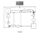
- FIG-1 of the drawings accompanying the specification is illustrated the basic flow diagram of the apparatus for filtration and disinfection of sea water / ship's ballast water and a method thereof of the present invention using simultaneous centrifugation and hydrodynamic cavitation which allows a ship to treat water that is being transported from one port to another while ballasting and de-ballasting.
- the system for ballast water treatment using a vortex diode (5) has water intake means (17) through which sea water enters from outside a vessel. The water is then pumped through a pump means, such as, but not limited to a ballast pump (18), into an inlet port on vortex diode (5) optionally through heat exchanger (4).
- the exhaust gases from the ships engine are used in this heat exchanger to manipulate the temperature of the ballast water entering the vortex diode (5).
- the filtration and cavitation is achieved through a vortex diode with single or multiple bleeding holes.
- the shape of the diode chamber, shape and size of inlet tangential port and outlet axial port, shape, size and number of bleeding holes control the quality of filtration and quality of cavitation occurring within the apparatus.
- the bleed water coming out of the bleeding holes of the diode chamber is recycled back to the intake means or discarded to the waterways.
- the treated ballast water is pumped from the vortex diode (5) to the ship's ballast tank (8).
- a quality control check can be performed prior to the receptacle (8) with appropriate method to monitor the quality of the treated water. If necessary, the water or a portion thereof in the receptacle (8) may be re-circulated with the help of deballasting pump (9), through the vortex diode (12), and back into the receptacle (8) by diverting the flow with valves (7 & 14) as preferably but optionally determined by and/or controlled by the quality monitoring system. It should be noted that the method and the apparatus represented in figure-1 could be located on a ship or any seafaring liner.
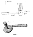
- FIG. 2 of the drawings represents a drawing showing cross section of vortex diode (item no.5 &12 in fig.1 and item E in fig.6 ) with details of arrangement of vortex diode and inline connecting flanges.
- the vortex diode of circular cross section shape comprises of single or multiple bleed holes.
- the ratio of diameter of the cavitation or diode chamber to the depth of the chamber is in the range of 2 to 12.
- the tapered tangential port and the diode chamber generate strong vortex flow within the chamber. Such vortex flow causes radial segregation of suspended solids and organisms within the diode chamber due to centrifugal action.
- the bleed-holes cause bleeding of part of the feed from the periphery of the diode chamber.
- the water coming out from the bleed-holes will have more concentration of heavier and larger suspended solids and organisms and thus realizes filtration.
- the size, number and location of bleed holes control the fraction of feed water going out from the bleed holes and effectiveness of filtration.
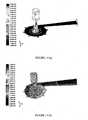
- FIG-3 of the drawings accompanying the specification is depicted examples of tangential outlet ports and axial inlet ports. As shown, expansion or contraction angle, length of inlet or outlet ports, expansion or contraction ratio and inlet velocity are the key design and operating parameters.
- the cavitation chamber comprises single or multiple bleeding holes.
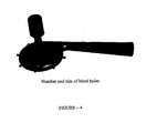
- FIG-4 of the drawings accompanying the specification is shown of a vortex diode with multiple bleed holes.
- the number, shape and size of bleed holes are crucial design parameters.
- the shape of the bleeding holes need not be circular and can be in principle of any shape.
- the slits or circular holes are the most obvious choices.
- the computational fluid dynamics (CFD) based models and Rayleigh-Plesset equation for cavitation collapse can be used for identifying preferably but not limited to (i) diameter of vortex diode; (ii) configuration of tangential inlet port; (iii) configuration of axial outlet port; (iv) fractional open area and number, diameter and distribution of bleed holes; (v) operating temperature; (vi) operating flow rate; (vii) number of re-circulations through cavitation chamber. It should be noted that for ensuring the desired overall disinfection effectiveness, it is essential to design a system which generates right number of cavitation events of adequate intensity. The number of cavitation events is dependent on perimeter of cavitation elements.
- the intensity of cavitation events depend on percentage open area or in other words on pressure drop across cavitating elements. It should be noted that different organisms would require different number density and intensity of cavitation events. Different cavitating elements can be fruitfully used in series or in parallel to optimize the overall system.
- cavitation preferably occurs for C v ⁇ 1 though under some conditions e.g. presence of gases/solid particles, cavitation may occur at C v > 1.
- Computational fluid dynamics (CFD) based models are used to simulate flow and to predict the instantaneous pressure field around the traveling cavity at any downstream location.
- the CFD models involve solution of conservation equations of mass, momentum and energy on a digital computer for a specific design/ configuration.
- the more detailed flow chart of 4 th box in figure-4 is shown in figure-7 of the drawings accompanying the specification, wherein is given the methodology of applying CFD for optimizing design of disinfector.
- the first step in CFD modeling is to model specific geometry of cavitation chamber/ elements and generate grids for further computations.
- the next step is to select appropriate governing equations for solving the flow in cavitation chamber/ elements.
- the flows relevant to cavitation are invariably turbulent.
- Several different models have been developed to simulate turbulent flows (see for example Ranade, 2002 and references cited therein).
- the fluctuating pressure field predicted by the CFD models is incorporated into a bubble dynamics equation to obtain the cavity radius history and the collapse pressures for a cavity of certain size, traveling with the fluid (see Pandit and Gogte, 2001; Ranade, 2002).
- CFD models are then used to optimize the overall configuration of cavitation chamber. The methodology is useful to optimize the overall system to meet the IMO guidelines on ballast water treatment.
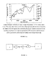
- Figure-5 of the drawings accompanying the specification shows a sample of results obtained using the methodology discussed above.
- Figure-5(a) shows predicted pressure field for one of the embodiments of the method and apparatus proposed in this invention.
- Figure-5(b) shows simulated path lines which might be generated in this embodiment.
- Figur-5(c) shows simulated dynamics and its eventual collapse of a single cavity.
- the present invention provides an apparatus and method for filtration and disinfection of ship's ballast water, such as sea water, based on centrifugation and hydrodynamic cavitation.
- the apparatus comprises a vortex diodes of circular cross section with single or multiple bleeding holes; tangential inlet ports and axial outlet ports.
- the chamber depth can be considered as a reference length scale. Typically the chamber diameter is in the range of 2 to 12 times the chamber depth, preferentially in the range of 4 to 8 times the chamber depth.
- the present invention provides an apparatus for filtration and disinfection of sea water / ship's ballast water, which comprises a water intake means (17 & 18) consisting of a ballast water intake source (17) and pump means (18) connected in series through a pressure gauge (3) and check valve(s) to an inlet port of a cavitation chamber of the form of vortex diode (5), optionally through an heat exchanger (4), characterized in that the said vortex diode cavitation chamber (5) essentially being provided on the periphery with single or multiple bleed holes of diameter(s) being in the range of 0.04 to 0.25 times the chamber depth, the output of the said vortex diode cavitation chamber (5) being passed through a quality check point (6) and check valve(s) (7) to a ballast tank (8), the output of the said ballast tank (8) being connected to a discharge pump (9) through check valve(s) to a discharge outlet and the bleed holes output from the said vortex diode cavitation chamber (5) being connected to
- the pump means (18) is one or a series of pumps such as, but not limited to a ballast pump.
- the heat exchanger (4) is connected to an energy source such as a standard source or method known in the art, or steam or engine exhaust gases from the ships engine.
- the ratio of diameter of the vortex diode cavitation chamber to the depth of the chamber is in the range of 2 to 12 and the said chamber being provided with tangential inlet port having a taper with angle ranging from 2 to 10 degrees and axial outlet port having a taper with angle ranging from 1 to 7 degrees and a smoothened expansion to a straight portion with expansion ratio on the range of 2 to 30.
- the inlet port ensures the smooth tangential entry of the fed water.
- the shortest diameter of the tangential inlet port is same as the depth of diode chamber.
- the diameter of the inlet port near the diode chamber is same as that of chamber depth.
- the vortex diode (5) comprises of single our multiple bleeding holes; wherein the number of bleeding holes is in the range of 1 to 60, having a fractional open area in the form of single or multiple holes which are either circular or non-circular with or without sharp edges and each hole is having diameter in the range of 500 micrometers to few millimeters.
- the water coming out of the bleed holes is recycled to the water intake means (17).
- the diameter of the bleeding holes is in the range of 4 to 25% of the chamber depth.
- the vortex diode (5) comprises a slot shaped bleeding outlet covering the entire periphery of the diode chamber.
- the diameter of vortex diode; (ii) the number of bleed holes; (iii) the location and spacing between bleed holes; (iv) the chamber depth (v) configuration of inlet and outlet ports; (vi) the operating temperature; (vii) the operating flow rate/ flow velocity; (viii) the number of re-circulations through vortex diode; are estimated and configured using computational fluid dynamics (CFD) based models and Rayleigh-Plesset equation for cavitation collapse, such as herein described.
- CFD computational fluid dynamics
- the quality check point (6) is provided with known devices capable of monitoring the quality of treated water.
- the discharge outlet of the said discharge pump (9) being connected through a pressure gauge (10) and check valve(s), optionally through an heat exchanger (11), to an inlet port of a vortex diode (12) having single or multiple cavitating elements and back to the said ballast tank (8) through a quality check point (13) and check valves (14, 7).
- the present invention provides a method for filtration and disinfection of sea water / ship's ballast water using the apparatus as herein above described, which comprises subjecting the ballast water to be treated to hydrodynamic cavitation by pumping the water intake of sea water, optionally pre-heated, into an inlet port of a vortex diode having single or multiple bleeding holes, the treated ballast water being passed through a quality check point to a ballast tank, re-circulating the treated water or a portion thereof if required by the quality check, for further hydrodynamic cavitation.
- the ballast water to be treated is optionally pre-heated to a temperature in the range of 10 to 70°C.
- the water flow rate through the vortex diode is such that the liquid velocities at the inlet are in the range of 1 to 15 m/s.
- the water pressure is in the range of 0.5 to 150 kg/cm 2 .
- the method for filtration and disinfection treatment of water using centrifugation and hydrodynamic cavitation is also suitable for a wide variety of water treatment applications including but not limited to wastewater management, agricultural applications, pool and space applications, oil and gas applications, and various disinfectant applications.
- the ballast water disinfection treatment herein described preferably though not exclusively occurs such that as the ship pumps sea water through a vortex diode, which has preferably but not limited to single or multiple bleeding holes.
- the pump means which may be one or a series of pumps, draws seawater from waterways surrounding the ship into the transfer piping means.
- the pumped seawater is passed through preferably but not limited to a heat exchanger.
- the energy source to heat this water may be a standard source or method known in the art, such as steam or engine exhaust gas or other.
- Control of the vortex diode may be through a regulator connected in series with the water intake line means that is connected to the cavitation chamber.
- the treated water expelled from the vortex diode is connected to a receptacle or optionally receptacles, which is preferably but optionally a ballast tank(s).
- the water collected from the bleed holes can be recycled back to water intake means or discarded to sea.
- the water treatment start-up and shut down will coincide with the vessel's water intake.
- a recirculation mechanism may be employed to further treat water and the need for such may be determined by an appropriate quality check system. Though at present, no in-line monitoring sensors are available by which organisms could be counted. However, elsewhere efforts are underway to devise sensors for detecting presence of specific pathogens. If a re-circulation mechanism needs to be activated, the shutdown operation, preferably although optionally, may be controlled by a control panel means. In use, it can now be understood the apparatus and method of water treatment may be used for a non-chemical, efficient treatment of water.
- the water pumping through the vortex diode gets disinfected due to hydrodynamic cavitation.
- cavities are generated due to the pressure fluctuations resulting from the strong vertical flow within a chamber.
- the generated cavities undergo various stages of the cavitation phenomena before violently collapsing, resulting in the release of large magnitudes of energy and highly reactive oxidizing species.
- the oxidizing species and conditions of high temperature and pressure are considered responsible for the disinfection of the micro-organisms.
- the quantum of the oxidizing species and the magnitude of temperature/pressure, hence the disinfection efficiency, is dependent on the geometric and operating conditions.
- any suitable cylindrical conduit made of a wide variety of metals, plastic, or other sturdy material may be used for the transfer piping means and/or re-circulation piping means described.
- the method and the apparatus of water treatment herein described may also be suitable for a wide variety of water treatment applications including but not limited to wastewater management, agricultural applications, pool and space applications, oil and gas applications, and various disinfectant applications.
- a wide variety of holds or tanks of many shapes and sizes, as well as an open body of water also may be used instead of the basic receptacle or ballast tank described.
- the method, configuration, size, shape and pressure and volume requirements may be adapted to conform to a wide variety of ships of a variety of shapes and sizes, and a closed recirculation system and method described may be transferable from one receptacle to another.
- the invention may also be adapted for use with a wide variety of pumps, receptacles, cavitation elements or sources, pressure valves and other components that are required by the invention but already present in a vessel or other treatment location.
- the novel apparatus and method of the present invention is capable of sterilizing hazardous organisms contained in ballast water stored in a ballast tank to effectively provide treatment of ballast water.
- the novelty of the present invention resides in the capability to provide a relatively low cost and eco-friendly apparatus and method based on hydrodynamic cavitation for efficient and economical disinfection of sea water / ship's ballast water by simply passing the organism infested water through single or multiple vortex diode, without use of any chemicals or any chemical reaction.
- the non-obvious inventive step of providing one or more cavitation chamber(s) without using flow constrictions harnesses the principle of conservation of angular momentum to generate low pressure regions within the chamber where cavitation occurs. Use of such a chamber with specially configured tangential inlet port and axial outlet port enables realization of the novelty of the apparatus of the present invention. Further, the non-obvious inventive step of combining the filtration and cavitation in a single equipment by providing single or multiple bleeding holes to the vortex diode enables realization of the novelty of the method of the present invention for filtration and disinfection of sea water / ship's ballast water.
- cavitation chamber (E) comprising of a diode chamber of diameter 35 mm and depth of 6 mm with tangential inlet and axial outlet ports.
- the flow in the cavitation chamber (E) is controlled by means of a flow regulating valve (C).
- a pressure gauge (D) is fitted prior to vortex diode (E), meant for recording cavitation pressure of the fluid.
- Post treated water from the outlet of cavitation chamber (E) is collected at the collection tank (F), and evaluated for the destruction level of the organisms.
- Zooplankton cells are collected by passing known quantity of intake (pre-cavitation) and discharge (post-cavitation) waters through a sieve made up of bolting silk with 50 ⁇ m mesh and suspended in a known quantity of filtered seawater. The zooplankton cells are then homogenized and an aliquot of this homogenate (0.1ml) after serial dilutions is plated on Zobell marine agar and incubated for 24 hours at ambient temperature. The colonies are enumerated thereafter and expressed as number per millilitre. The bacterial count in discharge water (post-cavitation) is compared with the intake water (pre-cavitation) and the percentage reduction in bacterial number is calculated as above.
- the biological count with regard to phytoplankton of cell size greater than 10 ⁇ m is assessed in the intake (pre-cavitation condition) and discharge (post-cavitation condition) waters.
- a known volume of intake water and discharge water is filtered through a sieve made up of bolting silk with 10 ⁇ m mesh.
- the phytoplankton cells retained on the 10 ⁇ m bolting silk are then immediately transferred into a known volume of filtered seawater.
- a sub sample of known volume is taken after thorough mixing and only pigmented cells with red chlorophyll fluorescence under UV light are enumerated using an inverted epifluorescence microscope and expressed as numbers per millilitre.
- the phytoplankton count in discharge water is compared with intake water and the percentage reduction in number is calculated as above.
- the biological count with regard to Zooplankton of size greater than 50 ⁇ m is assessed in the intake (pre-cavitation condition) and discharge (post-cavitation condition) waters.
- a known volume of intake water and discharge water is filtered through a sieve made up of bolting silk with 50 ⁇ m mesh.
- the Zooplankton cells retained on the sieve are then immediately transferred into a known volume of filtered seawater.
- a sub sample of known volume is taken after thorough mixing and only live zooplanktons (with mobility) are enumerated using a binocular microscope and expressed as numbers per cubic metre.
- the decomposition of aqueous solution of Potassium Iodide to form Iodine was used to identify occurrence and to evaluate the extent of cavitation.
- the decomposition of Potassium iodide (KI) was carried out using the vortex diode with chamber diameter, 35 mm; depth 6 mm and nozzle angle 7 degree, to estimate the extent of cavitation taking place in the same.
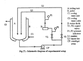
- the experimental setup used is shown in figure-7 of the drawings accompanying the specification. It consists of a holding tank of 10 liter capacity, fitted with a main line and a bypass line. Both these pipelines carry the liquid from the bottom of the tank and recirculate that to the tank. A centrifugal pump of power rating 1.75 kW is used to circulate the liquid.
- the pipelines end up well inside the tank to avoid the entrainment of air.
- the main line is fitted with the vortex diode.
- the vortex diode has a tangential inlet for the liquid and the outlet.is at the axial position.
- An Acrylic pipe is fitted at the outlet to visualize the turbulence due to cavity collapse.
- the pressure and flow rate of liquid through the mainline can be adjusted using the valves fitted to the bypass line as well as the main line.
- the pipelines with all of these fittings are totally of 4.5 liters capacity.
- the tank is provided with a jacket to circulate cooling water.
- Pressure Gauges are provided to measure the inlet and outlet pressures of the liquid flowing through the vortex diode.
- UV-VIS Spectrophotometer Appropriate calibration of UV-VIS Spectrophotometer by measuring the absorbance at 354 nm of known Iodine Concentration was carried out. 14 liter of 1% Potassium Iodide solution in distilled water was charged in the system. The bypass line valve was then adjusted to obtain the desired inlet pressure to the vortex diode. Cooling water was circulated through the jacket to control temperature at 40°C. Samples were collected at the interval of 10 minutes for one hour. These samples were kept in dark and their absorbance was immediately measured in the UV-VIS Spectrophotometer at 354 nm.
- the aforementioned patents and other water treatment systems and methods currently known in the art make no provisions as in the present invention for the disinfection / treatment of ballast water using hydrodynamic cavitation wherein the apparatus is essentially a vortex diode with tangential inlet ports and axial outlet port.
- the present invention provides an apparatus and method to treat ballast water using hydrodynamic cavitation in which ballast water is passed through a vortex diode with bleeding holes to realize simultaneous filtration and cavitation and overcomes the disadvantages and drawbacks noted in the prior art.
- the present invention provides an apparatus for isolation by centrifugation and disinfection of sea water / ship's ballast water and a method thereof, which has all the advantages of the prior art mentioned heretofore and many novel features that result in a system and method for ballast water treatment which is not anticipated, rendered obvious, suggested, or even implied by the prior art, either alone or in any combination thereof.
Landscapes
- Engineering & Computer Science (AREA)
- Chemical & Material Sciences (AREA)
- Mechanical Engineering (AREA)
- Environmental & Geological Engineering (AREA)
- Hydrology & Water Resources (AREA)
- Life Sciences & Earth Sciences (AREA)
- Ocean & Marine Engineering (AREA)
- Combustion & Propulsion (AREA)
- Water Supply & Treatment (AREA)
- Organic Chemistry (AREA)
- Health & Medical Sciences (AREA)
- General Health & Medical Sciences (AREA)
- Public Health (AREA)
- Toxicology (AREA)
- Physical Water Treatments (AREA)
Claims (10)
- Dispositif pour la filtration et la désinfection de l'eau de mer / eau de ballast des navires, qui comprend des moyens d'admission d'eau (17 & 18) consistant en une source d'admission d'eau de ballast (17) et des moyens de pompage (18) connectés en série par l'intermédiaire d'une jauge de pression (3) et de clapet(s) à un orifice d'entrée d'une chambre de cavitation de forme diode vortex (5), caractérisé en ce que ladite chambre de cavitation de forme diode vortex est munie en périphérie d'un ou plusieurs orifices d'évacuation de diamètre(s) allant de 0,01 à 0,25 fois la profondeur de la chambre, la sortie de ladite chambre de cavitation de forme diode vortex étant dirigée à travers un point de contrôle de qualité (6) et un ou plusieurs clapet(s) (7) vers un réservoir de ballast (8), la sortie dudit réservoir de ballast (8) étant reliée à une pompe de décharge (9) par l'intermédiaire d'un ou plusieurs clapet(s) à une sortie d'évacuation et la sortie des orifices d'évacuation de ladite chambre de cavitation de forme diode vortex (5) étant connectés à ladite source d'admission (17).
- Dispositif selon la revendication 1, dans lequel la source d'admission d'eau de ballast (17) est l'eau de mer et les moyens de pompage (18) comprennent une pompe de ballast.
- Dispositif selon la revendication 1 ou 2, dans lequel le diamètre du ou des orifice(s) d'évacuation va de 0,04 à 0,25 fois la profondeur de la chambre.
- Dispositif selon l'une des revendications 1 à 3, qui comprend de plus un échangeur de chaleur (4) situé avant la chambre de cavitation.
- Dispositif selon la revendication 4, dans lequel l'échangeur de chaleur (4) est relié à une source d'énergie, ladite source étant une source standard ou une méthode connue de l'état de la technique, ou de la vapeur ou les gaz d'échappement provenant du moteur du navire.
- Dispositif selon l'une des revendications 1 à 5, dans lequel le rapport du diamètre de la chambre de cavitation de forme diode vortex à la profondeur de la chambre est compris entre 2 et 12 et ladite chambre est munie d'un orifice d'entrée tangentiel ayant une pente dont l'angle est compris entre 2 et 10 degrés, et d'un orifice de sortie axial ayant une pente dont l'angle est compris entre 1 et 7 degrés, ledit orifice de sortie s'élargissant jusqu'à une portion droite avec un rapport d'expansion compris entre 2 et 30.
- Dispositif selon l'une des revendications 1 à 6, dans lequel le nombre d'orifices d'évacuation est compris entre 1 et 60, lesdits orifices étant circulaires ou non circulaires, avec ou sans arêtes vives et chaque orifice ayant un diamètre compris entre 500 micromètres et quelques millimètres.
- Dispositif selon l'une des revendications 1 à 7 comprenant, un orifice d'évacuation en forme de fente s'étendant autour de toute la périphérie de la chambre de cavitation.
- Dispositif selon l'une des revendications 1 à 7 dans lequel, afin de permettre la recirculation de l'eau traitée ou d'une partie de celle-ci si cela est nécessité par le point de contrôle de qualité (6), la sortie d'évacuation de ladite pompe d'évacuation (9) est reliée par l'intermédiaire d'un manomètre (10) et d'un ou plusieurs clapet(s), et éventuellement d'un échangeur de chaleur (11), à un orifice d'entrée d'une chambre de cavitation (12) ayant un ou plusieurs orifice(s) d'évacuation, et retour au réservoir de ballast (8) à travers un point de contrôle de qualité (13) et un ou plusieurs clapet(s) (14, 7).
- Méthode pour la filtration et la désinfection de l'eau de mer / eau de ballast des navires employant le dispositif tel que revendiqué ci-dessus, comprenant la soumission de l'eau de ballast à la cavitation hydrodynamique en pompant l'eau de mer, éventuellement préchauffée à une température comprise entre 10 et 70°C, vers un orifice d'entrée d'une chambre de cavitation munie d'un ou plusieurs orifice(s) d'évacuation, à un débit à travers ladite chambre de cavitation tel que les vitesses de liquide à l'orifice d'entrée tangentiel de la chambre sont comprises entre 1 et 15 m/s et la pression d'eau est comprise entre 0,5 et 150 kg/cm2, l'eau de ballast traitée étant amenée, après un point de contrôle de qualité, à un réservoir de ballast, et la recirculation de l'eau traitée ou d'une partie de celle-ci si cela est nécessité par le point de contrôle de qualité, pour une cavitation hydrodynamique supplémentaire.
Priority Applications (1)
| Application Number | Priority Date | Filing Date | Title |
|---|---|---|---|
| PL07736574T PL1996518T3 (pl) | 2006-03-20 | 2007-03-20 | Urządzenie oraz sposób do filtrowania i odkażania wody morskiej albo wody balastowej na statkach |
Applications Claiming Priority (2)
| Application Number | Priority Date | Filing Date | Title |
|---|---|---|---|
| IN734DE2006 | 2006-03-20 | ||
| PCT/IN2007/000114 WO2007108012A2 (fr) | 2006-03-20 | 2007-03-20 | Appareil de filtration et de désinfection d'eau de mer/de ballast de navire et procédé s'y rapportant |
Publications (2)
| Publication Number | Publication Date |
|---|---|
| EP1996518A2 EP1996518A2 (fr) | 2008-12-03 |
| EP1996518B1 true EP1996518B1 (fr) | 2011-09-14 |
Family
ID=38472866
Family Applications (1)
| Application Number | Title | Priority Date | Filing Date |
|---|---|---|---|
| EP07736574A Not-in-force EP1996518B1 (fr) | 2006-03-20 | 2007-03-20 | Appareil de filtration et de désinfection d'eau de mer/de ballast de navire et procédé s'y rapportant |
Country Status (6)
| Country | Link |
|---|---|
| US (1) | US7585416B2 (fr) |
| EP (1) | EP1996518B1 (fr) |
| AT (1) | ATE524417T1 (fr) |
| ES (1) | ES2374846T3 (fr) |
| PL (1) | PL1996518T3 (fr) |
| WO (1) | WO2007108012A2 (fr) |
Families Citing this family (32)
| Publication number | Priority date | Publication date | Assignee | Title |
|---|---|---|---|---|
| DE102005013673A1 (de) * | 2005-03-24 | 2006-09-28 | Hydac Process Technology Gmbh | Filteranlage und Verfahren zum Betrieb der Filteranlage |
| US9521858B2 (en) | 2005-10-21 | 2016-12-20 | Allen Szydlowski | Method and system for recovering and preparing glacial water |
| US9010261B2 (en) | 2010-02-11 | 2015-04-21 | Allen Szydlowski | Method and system for a towed vessel suitable for transporting liquids |
| ZA200803767B (en) * | 2005-11-08 | 2009-11-25 | Council Scient Ind Res | An apparatus for disinfection of sea water/ship's ballast water and a method thereof |
| US20090321365A1 (en) * | 2006-09-26 | 2009-12-31 | Emil Eriksson | System of water treatment |
| WO2010115800A2 (fr) * | 2009-04-03 | 2010-10-14 | Kjartan Ragnarsson | Navire conçu pour être utilisé comme une usine d'embouteillage mobile pour embouteiller des produits liquides |
| CH701271A2 (fr) | 2009-06-03 | 2010-12-15 | Hoppal R & D Sa | Dispositif de décontamination d'effluents aqueux par séparation de phases non miscibles et traitement germicide et/ou oxydant en vue de l'abattement de la DBO et/ou de la DCO. |
| US9371114B2 (en) | 2009-10-15 | 2016-06-21 | Allen Szydlowski | Method and system for a towed vessel suitable for transporting liquids |
| US9017123B2 (en) | 2009-10-15 | 2015-04-28 | Allen Szydlowski | Method and system for a towed vessel suitable for transporting liquids |
| US8924311B2 (en) | 2009-10-15 | 2014-12-30 | World's Fresh Waters Pte. Ltd. | Method and system for processing glacial water |
| KR101130730B1 (ko) * | 2009-10-29 | 2012-04-12 | 주식회사 파나시아 | 밸러스트수 처리장치 |
| US8101069B2 (en) * | 2009-11-10 | 2012-01-24 | Sky Bleu Martin | External filtering and absorbing device for use in a local containment area |
| US11584483B2 (en) | 2010-02-11 | 2023-02-21 | Allen Szydlowski | System for a very large bag (VLB) for transporting liquids powered by solar arrays |
| KR101012752B1 (ko) * | 2010-06-11 | 2011-02-08 | 주식회사 파나시아 | 밸러스트수 처리용 여과장치 |
| US8821720B2 (en) | 2010-06-11 | 2014-09-02 | Panasia Co., Ltd. | Filtering apparatus for treating ballast water |
| US8720379B2 (en) | 2010-08-12 | 2014-05-13 | St Reproductive Technologies, Llc | Shipping containers for livestock |
| BR112013002799A2 (pt) | 2010-08-05 | 2016-10-25 | St Reproductive Tech Llc | contêineres de embarque e métodos para transportar animais |
| AU2013201956B2 (en) * | 2010-08-05 | 2015-01-22 | St Reproductive Technologies, Llc | Systems and methods of transporting livestock |
| US9102258B2 (en) | 2010-08-05 | 2015-08-11 | St Reproductive Technologies, Llc | Floating partition, loft and troughs for a livestock shipping container |
| WO2013004240A1 (fr) * | 2011-07-06 | 2013-01-10 | Grundfos Holding A/S | Procédé de production et de stockage d'eau dessalée sur un navire de mer |
| PL2766314T3 (pl) | 2011-10-11 | 2019-10-31 | Council Scient Ind Res | Diody wirowe jako urządzenia do oczyszczania ścieków |
| US9725338B2 (en) | 2011-10-11 | 2017-08-08 | Council Of Scientific & Industrial Research | Apparatus and method for reduction in ammoniacal nitrogen from waste waters |
| US20140319075A1 (en) | 2011-11-16 | 2014-10-30 | Dennis Søgaard | Liquid treatment device |
| CN103359842B (zh) * | 2012-03-28 | 2015-05-13 | 刘爱东 | 无废水纯水机 |
| WO2014058556A1 (fr) * | 2012-10-08 | 2014-04-17 | Allen Szydlowski | Procédés et systèmes de production, d'échange et de transport d'eau |
| US20140229414A1 (en) | 2013-02-08 | 2014-08-14 | Ebay Inc. | Systems and methods for detecting anomalies |
| US9468863B2 (en) | 2013-07-09 | 2016-10-18 | Herbert J. Roth, Jr. | System and method of desalinating seawater |
| JP6439908B2 (ja) * | 2014-02-07 | 2018-12-19 | パナソニックIpマネジメント株式会社 | バラスト水中の微生物殺滅装置 |
| CN104556266B (zh) * | 2014-12-31 | 2016-04-06 | 陕西师范大学 | 一种强化水力空化处理装置 |
| KR101729652B1 (ko) * | 2016-08-22 | 2017-04-24 | 한국해양과학기술원 | 해양선박 평형수 및 어패류 양식 정화장치 |
| US10934180B1 (en) | 2020-03-31 | 2021-03-02 | KD Enterprises LLC | Hydrodynamic cavitation device |
| CN114590855A (zh) * | 2022-03-28 | 2022-06-07 | 山东建筑大学 | 一种热水水力空化消毒系统 |
Family Cites Families (33)
| Publication number | Priority date | Publication date | Assignee | Title |
|---|---|---|---|---|
| US3533506A (en) * | 1968-12-09 | 1970-10-13 | Wayne F Carr | Hydrocyclone |
| GB1571287A (en) * | 1976-06-22 | 1980-07-09 | Atomic Energy Authority Uk | Vortex diodes |
| US4249575A (en) * | 1978-05-11 | 1981-02-10 | United Kingdom Atomic Energy Authority | Fluidic devices |
| US5192451A (en) | 1991-05-06 | 1993-03-09 | Calgon Corporation | Method for controlling zebra mussels in ship ballast tanks |
| US5326468A (en) * | 1992-03-02 | 1994-07-05 | Cox Dale W | Water remediation and purification method and apparatus |
| US5816181A (en) | 1996-02-14 | 1998-10-06 | Sherman, Jr.; Thomas W. | Ballast water treatment system |
| US5932112A (en) | 1996-11-27 | 1999-08-03 | Browning Transport Management, Inc. | Method and apparatus for killing microorganisms in ship ballast water |
| US6125778A (en) | 1998-03-16 | 2000-10-03 | Rodden; Raymond M. | Ballast water treatment |
| DE19856071A1 (de) | 1998-12-04 | 2000-06-15 | Degussa | Verfahren zur Vermeidung einer Gewässerkontamination mit ortsfremden Organismen |
| JP2000167439A (ja) * | 1998-12-09 | 2000-06-20 | Katsuya Sanekata | キャビテーションノズルとキャビテーション発生システム |
| US6221260B1 (en) * | 1999-04-02 | 2001-04-24 | Dynaflow, Inc. | Swirling fluid jet cavitation method and system for efficient decontamination of liquids |
| US6402965B1 (en) * | 1999-07-13 | 2002-06-11 | Oceanit Laboratories, Inc. | Ship ballast water ultrasonic treatment |
| JP3358656B2 (ja) * | 1999-10-20 | 2002-12-24 | ホーヤ株式会社 | 眼鏡レンズ穴あけ治具位置決め装置 |
| IT1319468B1 (it) | 2000-05-22 | 2003-10-10 | Corghi Spa | Dispositivo stallonatore automatico per macchine smontagomme, emacchine smontagomme cosi' attrezzate |
| US6500345B2 (en) | 2000-07-31 | 2002-12-31 | Maritime Solutions, Inc. | Apparatus and method for treating water |
| US6835307B2 (en) | 2000-08-04 | 2004-12-28 | Battelle Memorial Institute | Thermal water treatment |
| WO2002072478A2 (fr) | 2000-11-06 | 2002-09-19 | Larry Russell | Traitement des eaux de ballast pour la maitrise des especes exotiques |
| KR20020036884A (ko) * | 2000-11-11 | 2002-05-17 | 김완모 | 캐비테이팅 워터젯을 이용한 오폐수 처리 시스템 |
| KR100654105B1 (ko) | 2000-11-28 | 2006-12-05 | 에코클로어 아이엔씨 | 밸러스트 워터의 유기물 제어 방법 및 장치 |
| US6516738B2 (en) | 2000-12-01 | 2003-02-11 | Nutech O3 | Method and apparatus for delivering ozone to ballast tanks |
| US6770248B2 (en) | 2001-05-04 | 2004-08-03 | Her Majesty The Queen In Right Of Canada, As Represented By The Minister Of National Defence Of Her Majesty's Canadian Government | Flowthrough device for the ultrasonic destruction of microorganisms in fluids |
| US6761123B2 (en) | 2001-05-25 | 2004-07-13 | Mh Systems | Infusion of combustion gases into ballast water preferably under less than atmospheric pressure to synergistically kill harmful aquatic nuisance species by simultaneous hypercapnia, hypoxia and acidic ph level |
| US20030015481A1 (en) | 2001-06-28 | 2003-01-23 | Eidem Ola Magne | Method and apparatus for treating/disinfecting ballast water in ships |
| US20050016933A1 (en) | 2001-11-28 | 2005-01-27 | Tom Perlich | Methods, apparatus, and compositions for controlling organisms in ballast water |
| US20030205136A1 (en) | 2002-05-02 | 2003-11-06 | Mcnulty Peter Drummond | System and method of water treatment |
| US7005074B2 (en) | 2002-06-29 | 2006-02-28 | Hap Nguyen | Ballast water treatment systems including related apparatus and methods |
| US20040099608A1 (en) | 2002-11-18 | 2004-05-27 | Leffler Charles E. | Ballast water treatment system |
| AU2003294487A1 (en) | 2003-11-20 | 2005-07-14 | Marine Environmental Partners, Inc. | Ballast water treatment system |
| RU2271300C2 (ru) * | 2003-11-28 | 2006-03-10 | Анатолий Иванович Харламов | Способ создания кавитирующих струй для обработки погруженных в жидкость поверхностей |
| JP2005246198A (ja) | 2004-03-03 | 2005-09-15 | Yoji Kato | 有害プランクトンの殺滅装置 |
| JP2005271648A (ja) | 2004-03-23 | 2005-10-06 | Miike Iron Works Co Ltd | 船舶のバラスト水の処理装置 |
| GB0411180D0 (en) * | 2004-05-19 | 2004-06-23 | Reederei Hesse Gmbh & Co Kg | Treatment of ballast water |
| ZA200803767B (en) | 2005-11-08 | 2009-11-25 | Council Scient Ind Res | An apparatus for disinfection of sea water/ship's ballast water and a method thereof |
-
2007
- 2007-03-20 PL PL07736574T patent/PL1996518T3/pl unknown
- 2007-03-20 US US11/726,399 patent/US7585416B2/en active Active
- 2007-03-20 EP EP07736574A patent/EP1996518B1/fr not_active Not-in-force
- 2007-03-20 AT AT07736574T patent/ATE524417T1/de not_active IP Right Cessation
- 2007-03-20 WO PCT/IN2007/000114 patent/WO2007108012A2/fr active Application Filing
- 2007-03-20 ES ES07736574T patent/ES2374846T3/es active Active
Also Published As
| Publication number | Publication date |
|---|---|
| WO2007108012A3 (fr) | 2007-12-06 |
| WO2007108012A2 (fr) | 2007-09-27 |
| EP1996518A2 (fr) | 2008-12-03 |
| US7585416B2 (en) | 2009-09-08 |
| US20080017591A1 (en) | 2008-01-24 |
| ES2374846T3 (es) | 2012-02-22 |
| PL1996518T3 (pl) | 2012-04-30 |
| ATE524417T1 (de) | 2011-09-15 |
Similar Documents
| Publication | Publication Date | Title |
|---|---|---|
| EP1996518B1 (fr) | Appareil de filtration et de désinfection d'eau de mer/de ballast de navire et procédé s'y rapportant | |
| EP1996517B1 (fr) | Appareil de desinfection d'eau de mer/d'eau de ballast d'un navire et procede associe | |
| Badve et al. | Microbial disinfection of seawater using hydrodynamic cavitation | |
| Gogate | Application of cavitational reactors for water disinfection: current status and path forward | |
| Tsolaki et al. | Technologies for ballast water treatment: a review | |
| Wu et al. | Removal of blue-green algae using the hybrid method of hydrodynamic cavitation and ozonation | |
| Gregg et al. | Review of two decades of progress in the development of management options for reducing or eradicating phytoplankton, zooplankton and bacteria in ship’s ballast water | |
| US9061925B2 (en) | Liquid treatment methods and apparatus | |
| KR20100017410A (ko) | 물 처리 시스템 | |
| US7595003B2 (en) | On-board water treatment and management process and apparatus | |
| Cvetković et al. | Application of hydrodynamic cavitation in ballast water treatment | |
| KR100928069B1 (ko) | 선박용 밸러스트 수 전처리 필터 및 그 처리 방법 | |
| Abu-Khader et al. | Ballast water treatment technologies: hydrocyclonic a viable option | |
| KR101494678B1 (ko) | 선박 평형수 처리 장치 | |
| Sangave et al. | Ballast water treatment using hydrodynamic cavitation | |
| Güney | Ballast water problem: Current status and expected challenges | |
| Chen et al. | The working principle of ballast water management system | |
| Nwigwe et al. | Review study of ballast water treatment system: Review of ballast water treatment system technologies. | |
| Szczepanek et al. | Assessment of selected on-board ballast water treatment systems in terms of technical and operational parameters | |
| RU2284964C1 (ru) | Способ стерилизации водных систем | |
| AU2012203894B2 (en) | Ballast water treatment methods and apparatus | |
| Steffens et al. | Ozon som alternativ for behandling av ballastvann | |
| McCluskey et al. | An overview of ballast water treatment methods | |
| EP3015435A1 (fr) | Dispositif de réduction de la contamination microbienne des eaux usées sans réactifs | |
| Liang et al. | Ballast water treatment technologies and shipboard demonstrations |
Legal Events
| Date | Code | Title | Description |
|---|---|---|---|
| PUAI | Public reference made under article 153(3) epc to a published international application that has entered the european phase |
Free format text: ORIGINAL CODE: 0009012 |
|
| 17P | Request for examination filed |
Effective date: 20080929 |
|
| AK | Designated contracting states |
Kind code of ref document: A2 Designated state(s): AT BE BG CH CY CZ DE DK EE ES FI FR GB GR HU IE IS IT LI LT LU LV MC MT NL PL PT RO SE SI SK TR |
|
| 17Q | First examination report despatched |
Effective date: 20100825 |
|
| GRAP | Despatch of communication of intention to grant a patent |
Free format text: ORIGINAL CODE: EPIDOSNIGR1 |
|
| DAX | Request for extension of the european patent (deleted) | ||
| GRAS | Grant fee paid |
Free format text: ORIGINAL CODE: EPIDOSNIGR3 |
|
| GRAA | (expected) grant |
Free format text: ORIGINAL CODE: 0009210 |
|
| AK | Designated contracting states |
Kind code of ref document: B1 Designated state(s): AT BE BG CH CY CZ DE DK EE ES FI FR GB GR HU IE IS IT LI LT LU LV MC MT NL PL PT RO SE SI SK TR |
|
| REG | Reference to a national code |
Ref country code: GB Ref legal event code: FG4D |
|
| REG | Reference to a national code |
Ref country code: CH Ref legal event code: EP |
|
| REG | Reference to a national code |
Ref country code: IE Ref legal event code: FG4D |
|
| REG | Reference to a national code |
Ref country code: DE Ref legal event code: R096 Ref document number: 602007017193 Country of ref document: DE Effective date: 20111124 |
|
| REG | Reference to a national code |
Ref country code: NL Ref legal event code: T3 |
|
| PG25 | Lapsed in a contracting state [announced via postgrant information from national office to epo] |
Ref country code: LT Free format text: LAPSE BECAUSE OF FAILURE TO SUBMIT A TRANSLATION OF THE DESCRIPTION OR TO PAY THE FEE WITHIN THE PRESCRIBED TIME-LIMIT Effective date: 20110914 Ref country code: SE Free format text: LAPSE BECAUSE OF FAILURE TO SUBMIT A TRANSLATION OF THE DESCRIPTION OR TO PAY THE FEE WITHIN THE PRESCRIBED TIME-LIMIT Effective date: 20110914 Ref country code: FI Free format text: LAPSE BECAUSE OF FAILURE TO SUBMIT A TRANSLATION OF THE DESCRIPTION OR TO PAY THE FEE WITHIN THE PRESCRIBED TIME-LIMIT Effective date: 20110914 |
|
| REG | Reference to a national code |
Ref country code: ES Ref legal event code: FG2A Ref document number: 2374846 Country of ref document: ES Kind code of ref document: T3 Effective date: 20120222 |
|
| LTIE | Lt: invalidation of european patent or patent extension |
Effective date: 20110914 |
|
| PG25 | Lapsed in a contracting state [announced via postgrant information from national office to epo] |
Ref country code: CY Free format text: LAPSE BECAUSE OF FAILURE TO SUBMIT A TRANSLATION OF THE DESCRIPTION OR TO PAY THE FEE WITHIN THE PRESCRIBED TIME-LIMIT Effective date: 20110914 Ref country code: SI Free format text: LAPSE BECAUSE OF FAILURE TO SUBMIT A TRANSLATION OF THE DESCRIPTION OR TO PAY THE FEE WITHIN THE PRESCRIBED TIME-LIMIT Effective date: 20110914 Ref country code: AT Free format text: LAPSE BECAUSE OF FAILURE TO SUBMIT A TRANSLATION OF THE DESCRIPTION OR TO PAY THE FEE WITHIN THE PRESCRIBED TIME-LIMIT Effective date: 20110914 Ref country code: LV Free format text: LAPSE BECAUSE OF FAILURE TO SUBMIT A TRANSLATION OF THE DESCRIPTION OR TO PAY THE FEE WITHIN THE PRESCRIBED TIME-LIMIT Effective date: 20110914 Ref country code: GR Free format text: LAPSE BECAUSE OF FAILURE TO SUBMIT A TRANSLATION OF THE DESCRIPTION OR TO PAY THE FEE WITHIN THE PRESCRIBED TIME-LIMIT Effective date: 20111215 |
|
| REG | Reference to a national code |
Ref country code: AT Ref legal event code: MK05 Ref document number: 524417 Country of ref document: AT Kind code of ref document: T Effective date: 20110914 |
|
| PG25 | Lapsed in a contracting state [announced via postgrant information from national office to epo] |
Ref country code: BE Free format text: LAPSE BECAUSE OF FAILURE TO SUBMIT A TRANSLATION OF THE DESCRIPTION OR TO PAY THE FEE WITHIN THE PRESCRIBED TIME-LIMIT Effective date: 20110914 |
|
| PG25 | Lapsed in a contracting state [announced via postgrant information from national office to epo] |
Ref country code: SK Free format text: LAPSE BECAUSE OF FAILURE TO SUBMIT A TRANSLATION OF THE DESCRIPTION OR TO PAY THE FEE WITHIN THE PRESCRIBED TIME-LIMIT Effective date: 20110914 Ref country code: IS Free format text: LAPSE BECAUSE OF FAILURE TO SUBMIT A TRANSLATION OF THE DESCRIPTION OR TO PAY THE FEE WITHIN THE PRESCRIBED TIME-LIMIT Effective date: 20120114 Ref country code: CZ Free format text: LAPSE BECAUSE OF FAILURE TO SUBMIT A TRANSLATION OF THE DESCRIPTION OR TO PAY THE FEE WITHIN THE PRESCRIBED TIME-LIMIT Effective date: 20110914 |
|
| REG | Reference to a national code |
Ref country code: PL Ref legal event code: T3 |
|
| PG25 | Lapsed in a contracting state [announced via postgrant information from national office to epo] |
Ref country code: EE Free format text: LAPSE BECAUSE OF FAILURE TO SUBMIT A TRANSLATION OF THE DESCRIPTION OR TO PAY THE FEE WITHIN THE PRESCRIBED TIME-LIMIT Effective date: 20110914 Ref country code: RO Free format text: LAPSE BECAUSE OF FAILURE TO SUBMIT A TRANSLATION OF THE DESCRIPTION OR TO PAY THE FEE WITHIN THE PRESCRIBED TIME-LIMIT Effective date: 20110914 Ref country code: PT Free format text: LAPSE BECAUSE OF FAILURE TO SUBMIT A TRANSLATION OF THE DESCRIPTION OR TO PAY THE FEE WITHIN THE PRESCRIBED TIME-LIMIT Effective date: 20120116 |
|
| PLBE | No opposition filed within time limit |
Free format text: ORIGINAL CODE: 0009261 |
|
| STAA | Information on the status of an ep patent application or granted ep patent |
Free format text: STATUS: NO OPPOSITION FILED WITHIN TIME LIMIT |
|
| PG25 | Lapsed in a contracting state [announced via postgrant information from national office to epo] |
Ref country code: DK Free format text: LAPSE BECAUSE OF FAILURE TO SUBMIT A TRANSLATION OF THE DESCRIPTION OR TO PAY THE FEE WITHIN THE PRESCRIBED TIME-LIMIT Effective date: 20110914 |
|
| 26N | No opposition filed |
Effective date: 20120615 |
|
| REG | Reference to a national code |
Ref country code: DE Ref legal event code: R097 Ref document number: 602007017193 Country of ref document: DE Effective date: 20120615 |
|
| PG25 | Lapsed in a contracting state [announced via postgrant information from national office to epo] |
Ref country code: MC Free format text: LAPSE BECAUSE OF NON-PAYMENT OF DUE FEES Effective date: 20120331 |
|
| REG | Reference to a national code |
Ref country code: CH Ref legal event code: PL |
|
| REG | Reference to a national code |
Ref country code: FR Ref legal event code: ST Effective date: 20121130 |
|
| REG | Reference to a national code |
Ref country code: IE Ref legal event code: MM4A |
|
| PG25 | Lapsed in a contracting state [announced via postgrant information from national office to epo] |
Ref country code: LI Free format text: LAPSE BECAUSE OF NON-PAYMENT OF DUE FEES Effective date: 20120331 Ref country code: CH Free format text: LAPSE BECAUSE OF NON-PAYMENT OF DUE FEES Effective date: 20120331 Ref country code: IE Free format text: LAPSE BECAUSE OF NON-PAYMENT OF DUE FEES Effective date: 20120320 Ref country code: FR Free format text: LAPSE BECAUSE OF NON-PAYMENT OF DUE FEES Effective date: 20120402 |
|
| PG25 | Lapsed in a contracting state [announced via postgrant information from national office to epo] |
Ref country code: BG Free format text: LAPSE BECAUSE OF FAILURE TO SUBMIT A TRANSLATION OF THE DESCRIPTION OR TO PAY THE FEE WITHIN THE PRESCRIBED TIME-LIMIT Effective date: 20111214 |
|
| PG25 | Lapsed in a contracting state [announced via postgrant information from national office to epo] |
Ref country code: MT Free format text: LAPSE BECAUSE OF FAILURE TO SUBMIT A TRANSLATION OF THE DESCRIPTION OR TO PAY THE FEE WITHIN THE PRESCRIBED TIME-LIMIT Effective date: 20110914 |
|
| PG25 | Lapsed in a contracting state [announced via postgrant information from national office to epo] |
Ref country code: TR Free format text: LAPSE BECAUSE OF FAILURE TO SUBMIT A TRANSLATION OF THE DESCRIPTION OR TO PAY THE FEE WITHIN THE PRESCRIBED TIME-LIMIT Effective date: 20110914 |
|
| PG25 | Lapsed in a contracting state [announced via postgrant information from national office to epo] |
Ref country code: LU Free format text: LAPSE BECAUSE OF NON-PAYMENT OF DUE FEES Effective date: 20120320 |
|
| PG25 | Lapsed in a contracting state [announced via postgrant information from national office to epo] |
Ref country code: HU Free format text: LAPSE BECAUSE OF FAILURE TO SUBMIT A TRANSLATION OF THE DESCRIPTION OR TO PAY THE FEE WITHIN THE PRESCRIBED TIME-LIMIT Effective date: 20070320 |
|
| PGFP | Annual fee paid to national office [announced via postgrant information from national office to epo] |
Ref country code: ES Payment date: 20150324 Year of fee payment: 9 Ref country code: NL Payment date: 20150303 Year of fee payment: 9 Ref country code: DE Payment date: 20150304 Year of fee payment: 9 Ref country code: IT Payment date: 20150316 Year of fee payment: 9 |
|
| PGFP | Annual fee paid to national office [announced via postgrant information from national office to epo] |
Ref country code: PL Payment date: 20150305 Year of fee payment: 9 Ref country code: GB Payment date: 20150305 Year of fee payment: 9 |
|
| REG | Reference to a national code |
Ref country code: DE Ref legal event code: R119 Ref document number: 602007017193 Country of ref document: DE |
|
| REG | Reference to a national code |
Ref country code: NL Ref legal event code: MM Effective date: 20160401 |
|
| GBPC | Gb: european patent ceased through non-payment of renewal fee |
Effective date: 20160320 |
|
| PG25 | Lapsed in a contracting state [announced via postgrant information from national office to epo] |
Ref country code: NL Free format text: LAPSE BECAUSE OF NON-PAYMENT OF DUE FEES Effective date: 20160401 Ref country code: DE Free format text: LAPSE BECAUSE OF NON-PAYMENT OF DUE FEES Effective date: 20161001 Ref country code: GB Free format text: LAPSE BECAUSE OF NON-PAYMENT OF DUE FEES Effective date: 20160320 |
|
| PG25 | Lapsed in a contracting state [announced via postgrant information from national office to epo] |
Ref country code: IT Free format text: LAPSE BECAUSE OF NON-PAYMENT OF DUE FEES Effective date: 20160320 |
|
| PG25 | Lapsed in a contracting state [announced via postgrant information from national office to epo] |
Ref country code: PL Free format text: LAPSE BECAUSE OF NON-PAYMENT OF DUE FEES Effective date: 20160320 |
|
| PG25 | Lapsed in a contracting state [announced via postgrant information from national office to epo] |
Ref country code: ES Free format text: LAPSE BECAUSE OF NON-PAYMENT OF DUE FEES Effective date: 20160321 |
|
| REG | Reference to a national code |
Ref country code: ES Ref legal event code: FD2A Effective date: 20181205 |