EP1995809A1 - Fuel cell having metallic separator plate with intersecting cooling channels - Google Patents
Fuel cell having metallic separator plate with intersecting cooling channels Download PDFInfo
- Publication number
- EP1995809A1 EP1995809A1 EP08009412A EP08009412A EP1995809A1 EP 1995809 A1 EP1995809 A1 EP 1995809A1 EP 08009412 A EP08009412 A EP 08009412A EP 08009412 A EP08009412 A EP 08009412A EP 1995809 A1 EP1995809 A1 EP 1995809A1
- Authority
- EP
- European Patent Office
- Prior art keywords
- coolant
- flow field
- metal separator
- fuel cell
- buffer
- Prior art date
- Legal status (The legal status is an assumption and is not a legal conclusion. Google has not performed a legal analysis and makes no representation as to the accuracy of the status listed.)
- Granted
Links
Images


Classifications
-
- H—ELECTRICITY
- H01—ELECTRIC ELEMENTS
- H01M—PROCESSES OR MEANS, e.g. BATTERIES, FOR THE DIRECT CONVERSION OF CHEMICAL ENERGY INTO ELECTRICAL ENERGY
- H01M8/00—Fuel cells; Manufacture thereof
- H01M8/02—Details
- H01M8/0202—Collectors; Separators, e.g. bipolar separators; Interconnectors
- H01M8/0267—Collectors; Separators, e.g. bipolar separators; Interconnectors having heating or cooling means, e.g. heaters or coolant flow channels
-
- H—ELECTRICITY
- H01—ELECTRIC ELEMENTS
- H01M—PROCESSES OR MEANS, e.g. BATTERIES, FOR THE DIRECT CONVERSION OF CHEMICAL ENERGY INTO ELECTRICAL ENERGY
- H01M8/00—Fuel cells; Manufacture thereof
- H01M8/02—Details
- H01M8/0202—Collectors; Separators, e.g. bipolar separators; Interconnectors
- H01M8/0258—Collectors; Separators, e.g. bipolar separators; Interconnectors characterised by the configuration of channels, e.g. by the flow field of the reactant or coolant
- H01M8/026—Collectors; Separators, e.g. bipolar separators; Interconnectors characterised by the configuration of channels, e.g. by the flow field of the reactant or coolant characterised by grooves, e.g. their pitch or depth
-
- H—ELECTRICITY
- H01—ELECTRIC ELEMENTS
- H01M—PROCESSES OR MEANS, e.g. BATTERIES, FOR THE DIRECT CONVERSION OF CHEMICAL ENERGY INTO ELECTRICAL ENERGY
- H01M8/00—Fuel cells; Manufacture thereof
- H01M8/02—Details
- H01M8/0271—Sealing or supporting means around electrodes, matrices or membranes
- H01M8/0273—Sealing or supporting means around electrodes, matrices or membranes with sealing or supporting means in the form of a frame
-
- H—ELECTRICITY
- H01—ELECTRIC ELEMENTS
- H01M—PROCESSES OR MEANS, e.g. BATTERIES, FOR THE DIRECT CONVERSION OF CHEMICAL ENERGY INTO ELECTRICAL ENERGY
- H01M8/00—Fuel cells; Manufacture thereof
- H01M8/24—Grouping of fuel cells, e.g. stacking of fuel cells
- H01M8/241—Grouping of fuel cells, e.g. stacking of fuel cells with solid or matrix-supported electrolytes
- H01M8/242—Grouping of fuel cells, e.g. stacking of fuel cells with solid or matrix-supported electrolytes comprising framed electrodes or intermediary frame-like gaskets
-
- H—ELECTRICITY
- H01—ELECTRIC ELEMENTS
- H01M—PROCESSES OR MEANS, e.g. BATTERIES, FOR THE DIRECT CONVERSION OF CHEMICAL ENERGY INTO ELECTRICAL ENERGY
- H01M8/00—Fuel cells; Manufacture thereof
- H01M8/24—Grouping of fuel cells, e.g. stacking of fuel cells
- H01M8/2457—Grouping of fuel cells, e.g. stacking of fuel cells with both reactants being gaseous or vaporised
-
- H—ELECTRICITY
- H01—ELECTRIC ELEMENTS
- H01M—PROCESSES OR MEANS, e.g. BATTERIES, FOR THE DIRECT CONVERSION OF CHEMICAL ENERGY INTO ELECTRICAL ENERGY
- H01M8/00—Fuel cells; Manufacture thereof
- H01M8/24—Grouping of fuel cells, e.g. stacking of fuel cells
- H01M8/2465—Details of groupings of fuel cells
- H01M8/2483—Details of groupings of fuel cells characterised by internal manifolds
-
- H—ELECTRICITY
- H01—ELECTRIC ELEMENTS
- H01M—PROCESSES OR MEANS, e.g. BATTERIES, FOR THE DIRECT CONVERSION OF CHEMICAL ENERGY INTO ELECTRICAL ENERGY
- H01M8/00—Fuel cells; Manufacture thereof
- H01M8/10—Fuel cells with solid electrolytes
- H01M2008/1095—Fuel cells with polymeric electrolytes
-
- H—ELECTRICITY
- H01—ELECTRIC ELEMENTS
- H01M—PROCESSES OR MEANS, e.g. BATTERIES, FOR THE DIRECT CONVERSION OF CHEMICAL ENERGY INTO ELECTRICAL ENERGY
- H01M8/00—Fuel cells; Manufacture thereof
- H01M8/02—Details
- H01M8/0202—Collectors; Separators, e.g. bipolar separators; Interconnectors
- H01M8/0204—Non-porous and characterised by the material
- H01M8/0206—Metals or alloys
-
- Y—GENERAL TAGGING OF NEW TECHNOLOGICAL DEVELOPMENTS; GENERAL TAGGING OF CROSS-SECTIONAL TECHNOLOGIES SPANNING OVER SEVERAL SECTIONS OF THE IPC; TECHNICAL SUBJECTS COVERED BY FORMER USPC CROSS-REFERENCE ART COLLECTIONS [XRACs] AND DIGESTS
- Y02—TECHNOLOGIES OR APPLICATIONS FOR MITIGATION OR ADAPTATION AGAINST CLIMATE CHANGE
- Y02E—REDUCTION OF GREENHOUSE GAS [GHG] EMISSIONS, RELATED TO ENERGY GENERATION, TRANSMISSION OR DISTRIBUTION
- Y02E60/00—Enabling technologies; Technologies with a potential or indirect contribution to GHG emissions mitigation
- Y02E60/30—Hydrogen technology
- Y02E60/50—Fuel cells
Definitions
- the present invention relates to a fuel cell formed by stacking a membrane electrode assembly and metal separators of corrugated plates in a stacking direction.
- the membrane electrode assembly includes a pair of electrodes, and an electrolyte interposed between the electrodes.
- a reactant gas flow field is formed in the fuel cell for supplying a reactant gas along an electrode surface in a direction of gravity or in a horizontal direction.
- a coolant flow field is formed in the fuel cell for supplying a coolant in a direction intersecting the flow direction of the reactant gas of the reactant gas flow field.
- a solid polymer electrolyte fuel cell employs a membrane electrode assembly which includes an anode, a cathode, and an electrolyte membrane interposed between the anode and the cathode.
- the electrolyte membrane is a polymer ion exchange membrane.
- the membrane electrode assembly is sandwiched between separators to form a power generation cell.
- a predetermined number of power generation cells are stacked together to form a fuel cell stack.
- a fuel gas flow field (hereinafter also referred to as the "reactant gas flow field") for supplying a fuel gas along an anode and an oxygen-containing gas flow field (hereinafter also referred to as the "reactant gas flow field”) for supplying an oxygen-containing gas along a cathode are formed in surfaces of separators facing the anode and the cathode, respectively. Further, a coolant flow field for supplying a coolant is formed along surfaces of the separators for each of the power generation cells, or for every predetermined number of the power generation cells.
- the fuel cell may adopt so called the internal manifold structure in which reactant gas passages and coolant passages extending in the stacking direction of the separators are provided in the fuel cell.
- buffers are provided between the reactant gas passages and the reactant gas flow field for supplying, and dispersing the reactant gas to the reactant gas flow field uniformly.
- an oxygen-containing gas inlet manifold 2a, a coolant inlet manifold 3a, a fuel gas inlet manifold 4a extend through a sheet metal element 1 at one end in a longitudinal direction.
- An oxygen-containing gas outlet manifold 2b, a coolant outlet manifold 3b, and a fuel gas outlet manifold 4b extend through the sheet metal element 1 at the other end in the longitudinal direction.
- a straight corrugated flow field 5 is formed in a cooling surface of the sheet metal element 1.
- An inlet buffer 6a and an outlet buffer 6b each including dimples or rails are provided at opposite ends of the corrugated flow field 5.
- the inlet buffer 6a and the outlet buffer 6b are provided at positions corresponding to inlet buffers and outlet buffers of flow fields for the fuel gas and the oxygen-containing gas. It is because the flow direction of the coolant is the same as the flow directions of the fuel gas and the oxygen-containing gas.
- the inlet buffer 6a and the outlet buffer 6b are provided on the cooling surface of the sheet metal element 1.
- the coolant supplied from the coolant inlet manifold 3a flows from the inlet buffer 6a to the corrugated flow field 5, and the coolant is discharged from the corrugated flow field 5 to the coolant outlet manifold 3b through the outlet buffer 6b.
- the coolant flows into the inlet buffer 6a and the outlet buffer 6b where power generation is not performed and cooling is not required. Therefore, the flow rate of the supplied coolant needs to be larger than the flow rate of the coolant which is actually required for cooling the power generation area. Thus, loss of electrical energy in the coolant pump is large, and the system efficiency is low.
- a main object of the present invention is to provide a fuel cell, in particular, having structure in which the flow direction of a coolant intersects the flow directions of reactant gases, entry of the coolant into the back surface of a reactant gas buffer (hereinafter referred to as a "back surface buffer”) is reliably prevented, and power generation is carried out efficiently and economically.
- the present invention relates to a fuel cell formed by stacking a membrane electrode assembly and metal separators of corrugated plates in a stacking direction.
- the membrane electrode assembly includes a pair of electrodes, and an electrolyte membrane interposed between the electrodes.
- a reactant gas flow field is formed in the fuel cell for supplying a reactant gas along an electrode surface, and a coolant flow field is formed in the fuel cell for supplying a coolant in a direction intersecting a flow direction of the reactant gas of the reactant gas flow field.
- a reactant gas passage and a coolant passage extend through the metal separators for allowing the reactant gas and the coolant to flow in the stacking direction.
- Each of the metal separators has a buffer connecting the reactant gas passage and the reactant gas flow field.
- At least one of the metal separators includes a protrusion protruding toward the coolant flow field between the reactant gas flow field and the buffer, to limit flow of the coolant into a back surface buffer as a back surface of the buffer.
- the flow of the coolant is limited by the protrusions between the coolant passages and the back surface buffer. Therefore, the coolant flows along the coolant flow field reliably and suitably. Thus, it is possible to reduce the required flow rate of the coolant, and loss of electrical energy in the coolant pump is reduced, and improvement in the system efficiency is achieved easily.
- the protrusions of the coolant flow field form the grooves in the reactant gas flow field.
- the reactant gas is distributed in the reactant gas flow field uniformly. Therefore, improvement in the power generation performance is achieved advantageously. Further, since the coolant is distributed to the power generation area uniformly, generation of local hot spots does not occur, and the temperature degradation of the electrolyte membrane can be reduced.
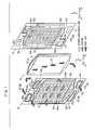
- a fuel cell 10 is formed by stacking a plurality of power generation cells 12 in a direction indicated by an arrow A. At opposite ends of the fuel cell 10 in the stacking direction, end plates (not shown) are provided. The stacked power generation cells 12 between the end plates are fixed together by tie rods (not shown). Alternatively, the power generation cells 12 are placed in a casing (not shown), and a predetermined tightening load is applied to the power generation cells 12 in the direction indicated by the arrow A.
- Each of the power generation cells 12 includes a membrane electrode assembly 16 and an anode side first metal separator 18 and a cathode side second metal separator 20 sandwiching the membrane electrode assembly 16.
- the first metal separator 18 and the second metal separator 20 have ridges and grooves in cross section by corrugating metal thin plates under pressure.
- first metal separator 18 and the second metal separator 20 are steel plates, stainless steel plates, aluminum plates, plated steel sheets, or metal plates having anti-corrosive surfaces by surface treatment.
- an oxygen-containing gas supply passage (reactant gas passage) 22a for supplying an oxygen-containing gas and a fuel gas supply passage (reactant gas passage) 24a for supplying a fuel gas such as a hydrogen-containing gas are provided.
- the oxygen-containing gas supply passage 22a and the fuel gas supply passage 24a extend through the power generation cell 12 in the direction indicated by the arrow A.
- a fuel gas discharge passage (reactant gas passage) 24b for discharging the fuel gas and an oxygen-containing gas discharge passage (reactant gas passage) 22b for discharging the oxygen-containing gas are provided.
- the fuel gas discharge passage 24b and the oxygen-containing gas discharge passage 22b extend through the power generation cell 12 in the direction indicated by the arrow A.
- a coolant supply passage 26a for supplying a coolant is provided at one end of the power generation cell 12 in a lateral direction indicated by an arrow B.
- a coolant discharge passage 26b for discharging the coolant is provided at the other end of the power generation cell 12 in the lateral direction.
- the coolant supply passage 26a and the coolant discharge passage 26b extend through the power generation cell 12 in the direction indicated by the arrow A.
- the membrane electrode assembly 16 includes an anode 30, a cathode 32, and a solid polymer electrolyte membrane 28 interposed between the anode 30 and the cathode 32.
- the solid polymer electrolyte membrane 28 is formed by impregnating a thin membrane of perfluorosulfonic acid with water, for example.
- the surface area of the anode 30 is smaller than the surface area of the cathode 32.
- Each of the anode 30 and the cathode 32 has a gas diffusion layer (not shown) such as a carbon paper, and an electrode catalyst layer (not shown) of platinum alloy supported on porous carbon particles.
- the carbon particles are deposited uniformly on the surface of the gas diffusion layer.
- the electrode catalyst layer of the anode 30 and the electrode catalyst layer of the cathode 32 are fixed to both surfaces of the solid polymer electrolyte membrane 28, respectively.
- the first metal separator 18 has a fuel gas flow field 34 on its surface 18a facing the membrane electrode assembly 16.
- the fuel gas flow field 34 is connected between the fuel gas supply passage 24a and the fuel gas discharge passage 24b.
- the fuel gas flow field 34 has a plurality of corrugated flow grooves 34a extending in a direction indicated by an arrow C.
- An inlet buffer 36a and an outlet buffer 36b are provided at upper and lower ends of the corrugated flow grooves 34a in the direction indicated by the arrow C.
- the inlet buffer 36a and the outlet buffer 36b include a plurality of bosses 37a, 37b. Each of the inlet buffer 36a and the outlet buffer 36b has a substantially triangular shape with the center in the width direction protruding upwardly and downwardly. Press lines (protrusions) 38a, 38b protruding toward a coolant flow field 54 as described later (toward the surface 18b) are formed by pressure forming, between the fuel gas flow field 34 and the inlet buffer 36a, and between the fuel gas flow field 34 and the outlet buffer 36b, respectively.
- a plurality of receivers 40a and a plurality of receivers 40b are provided on the surface 18a of the first metal separator 18.
- the receivers 40a form a connection channel connecting the fuel gas supply passage 24a and the inlet buffer 36a.
- the receivers 40b form a connection channel connecting the fuel gas discharge passage 24b and the outlet buffer 36b.
- a plurality of supply holes 42a and a plurality of discharge holes 42b are provided adjacent to the receivers 40a, 40b, respectively.
- the supply holes 42a are connected to the fuel gas supply passage 24a on the surface 18b, and likewise, the discharge holes 42b are connected to the fuel gas discharge passage 24b on the surface 18b (see FIG. 4 ).
- the second metal separator 20 has an oxygen-containing gas flow field 44 on its surface 20a facing the membrane electrode assembly 16.
- the oxygen-containing gas flow field 44 is connected between the oxygen-containing gas supply passage 22a and the oxygen-containing gas discharge passage 22b.
- the oxygen-containing gas flow field 44 has a plurality of corrugated flow grooves 44a extending in a direction indicated by the arrow C.
- An inlet buffer 46a and an outlet buffer 46b are provided at upper and lower ends of the corrugated flow grooves 44a in the direction indicated by the arrow C.
- the inlet buffer 46a and the outlet buffer 46b include a plurality of bosses 47a, 47b. Each of the inlet buffer 46a and the outlet buffer 46b has a substantially triangular shape with the center in the width direction protruding upwardly and downwardly. Press lines (protrusions) 48a, 48b protruding toward a coolant flow field 54 as described later (toward the surface 20b) are formed by pressure forming (see FIG. 2 ), between the oxygen-containing gas flow field 44 and the inlet buffer 46a, and between the oxygen-containing gas flow field 44 and the outlet buffer 46b, respectively.
- a plurality of receivers 50a and a plurality of receivers 50b are provided on the surface 20a of the second metal separator 20.
- the receivers 50a form a connection channel connecting the oxygen-containing gas supply passage 22a and the inlet buffer 46a
- the receivers 50b form a connection channel connecting the oxygen-containing gas discharge passage 22b and the outlet buffer 46b.
- a coolant flow field 54 is formed between the surface 18b of the first metal separator 18 and the surface 20b of the second metal separator 20.
- the coolant flow field 54 is connected between the coolant supply passage 26a and the coolant discharge passage 26b. That is, the back surface of the fuel gas flow field 34 and the back surface of the oxygen-containing gas flow field 44 are overlapped with each other to form the coolant flow field 54 extending in the direction indicated by the arrow B. Specifically, the back surface of the corrugated flow grooves 34a and the back surface of the corrugated flow grooves 44a are overlapped with each other to form the coolant flow field 54.
- back surface buffers 56a, 56b are provided at upper and lower ends of the coolant flow field 54 in the direction indicated by the arrow C. That is, the back surface buffers 56a, 56b are provided on the back surfaces of the inlet buffer 36a and the outlet buffer 36b, and have substantially triangular shapes, respectively.
- the shapes of the back surface buffers 56a, 56b correspond to the shapes of the back surfaces of the inlet buffer 36a and the outlet buffer 36b, respectively.
- a plurality of bosses 58a, 58b are provided in the back surface buffers 56a, 56b.
- the surface 20b of the second metal separator 20 and the surface 18b of the first metal separator 18 have the same structure, and detailed description thereof will be omitted.
- the first metal separator 18 of one of the adjacent power generation cells 12 and the second metal separator 20 of the other of the adjacent power generation cells 12 are directly stacked together to form the coolant flow field 54.
- the press lines 38a, 38b, and the press lines 48b, 48b contact each other to limit the flow of coolant into the back surface buffers 56a, 56b.
- a first seal member 62 is provided integrally with the surfaces 18a, 18b of the first metal separator 18, around the outer end of the first metal separator 18.
- a second seal member 64 as a planar seal is provided integrally with the surfaces 20a, 20b of the second metal separator 20, around the outer end of the second metal separator 20.
- Each of the first and second seal members 62, 64 is made of seal material, cushion material, or packing material such as an EPDM (ethylene propylene diene monomer) rubber, an NBR (nitrile butadiene rubber), a fluoro rubber, a silicone rubber, a fluorosilicone rubber, a Butyl rubber, a natural rubber, a styrene rubber, a chloroprene rubber, or an acrylic rubber.
- the first seal member 62 includes an inner seal 62a provided around the fuel gas flow field 34 and an outer seal 62b provided outside the inner seal 62a.
- the inner seal 62a is a ridge seal formed around the fuel gas flow field 34, the inlet buffer 36a, the outlet buffer 36b, the supply holes 42a and the discharge holes 42b.
- the first seal member 62 has an inner seal 62c provided around the coolant flow field 54 and an outer seal 62d provided outside the inner seal 62c.
- the inner seal 62a and the outer seal 62b are provided at positions corresponding to the inner seal 62c and the outer seal 62d, respectively.
- the inner seal 62c is provided around the coolant flow field 54, the coolant supply passage 26a, and the coolant discharge passage 26b, and covers the back surface buffers 56a, 56b (see FIG. 4 ).
- the coolant supply passage 26a and the coolant discharge passage 26b are connected to the coolant flow field 54 through the connection channels 66a, 66b, respectively.
- an oxygen-containing gas is supplied to the oxygen-containing gas supply passage 22a, and a fuel gas such as a hydrogen-containing gas is supplied to the fuel gas supply passage 24a. Further, a coolant such as pure water or ethylene glycol is supplied to the coolant supply passage 26a.
- the oxygen-containing gas, the fuel gas, and the coolant are supplied in the direction indicated by the arrow A, to the power generation cells 12 stacked together in the direction indicated by the arrow A.
- the oxygen-containing gas flows from the oxygen-containing gas supply passage 22a to the oxygen-containing gas flow field 44 of the second metal separator 20, and flows along the cathode 32 of the membrane electrode assembly 16 for inducing an electrochemical reaction at the cathode 32.
- the oxygen-containing gas flowing through the oxygen-containing gas supply passage 22a passes through spaces between the receivers 50a, and then, the oxygen-containing gas is supplied to the inlet buffer 46a.
- the oxygen-containing supplied to the inlet buffer 46a is dispersed in the direction indicated by the arrow B, and flows downwardly along the corrugated flow grooves 44a of the oxygen-containing gas flow field 44.
- the oxygen-containing gas is supplied to the cathode 32 of the membrane electrode assembly 16 for inducing an electrochemical reaction at the cathode 32.
- the fuel gas flows from the fuel gas supply passage 24a into the supply holes 42a to the surface 18a.
- the fuel gas passes through spaces between the receivers 40a, and then, the fuel gas is supplied into the inlet buffer 36a.
- the fuel gas is dispersed in the direction indicated by the arrow B in the inlet buffer 36a and flows downwardly along the corrugated flow grooves 34a of the fuel gas flow field 34.
- the fuel gas is supplied to the anode 30 of the membrane electrode assembly 16 for inducing an electrochemical reaction at the anode 30.
- the oxygen-containing gas supplied to the cathode 32, and the fuel gas supplied to the anode 30 are consumed in the electrochemical reactions at catalyst layers of the cathode 32 and the anode 30 for generating electricity (see FIG. 2 ).
- the oxygen-containing gas consumed at the cathode 32 flows to the outlet buffer 46b connected to a lower portion of the oxygen-containing gas flow field 44.
- the oxygen-containing gas from the outlet buffer 46b passes through spaces between the receivers 50b, and the oxygen-containing gas is discharged into the oxygen-containing gas discharge passage 22b.
- the fuel gas consumed at the anode 30 flows to the outlet buffer 36b connected to a lower portion of the fuel gas flow field 34.
- the fuel gas passes through spaces between the receivers 40b. Then, the fuel gas flows through the discharge holes 42b to the surface 18b, and the fuel gas is discharged into the fuel gas discharge passage 24b.
- the coolant flows from the coolant supply passage 26a into the coolant flow field 54 between the first and second metal separators 18, 20, the coolant flows in the horizontal direction indicated by the arrow B. After the coolant cools the membrane electrode assembly 16, the coolant is discharged into the coolant discharge passage 26b.
- the first metal separator 18 of one of the adjacent power generation cells 12 and the second metal separator 20 of the other of the adjacent power generation cells 12 are directly stacked together to form the coolant flow field 54.
- the press lines 38a, 38b and the press lines 48a, 48b contact each other to limit the flow of the coolant into the back surface buffers 56a, 56b.
- the coolant flows reliably and suitably along the coolant flow field 54 without undesirably flowing through the back surface buffers 56a, 56b, and it is possible to suitably reduce the required flow rate of the coolant.
- the energy loss in the coolant pump (not shown) is reduced effectively, and improvement in the overall system efficiency in the fuel cell 10 is achieved easily.
- press lines 38a, 48a form part of protrusions on the surface where the coolant flow field 54 is provided, and part of grooves on the surfaces where the fuel gas flow field 34 and the oxygen-containing gas flow field 44 are provided.
- the fuel gas and the oxygen-containing gas are distributed uniformly and reliably over the fuel gas flow field 34 and the oxygen-containing gas flow field 44, and improvement in the power generation performance is achieved advantageously.
- the coolant is distributed uniformly into the power generation area of the membrane electrode assembly 16.
- generation of local hot spots is prevented effectively, and in particular, the desired temperature in the solid polymer electrolyte membrane 28 is maintained advantageously.
- the gases flow in the fuel gas flow field 34 and the oxygen-containing gas flow field 44 in the direction of gravity indicated by the arrow C, and the coolant flows in the coolant flow field 54 in the horizontal direction indicated by the arrow B.
- the gases may flow in the fuel gas flow field 34 and the oxygen-containing gas flow field 44 in the horizontal direction, and the coolant may flow in the coolant flow field 54 in the direction of gravity.
- FIG. 5 is a cross sectional view showing main components of a fuel cell 80 according to a second embodiment of the present invention.
- the constituent elements that are identical to those of the fuel cell 10 according to the first embodiment are labeled with the same reference numerals, and description thereof will be omitted. Further, also in third and fourth embodiments as descried later, the constituent elements that are identical to those of the fuel cell 10 according to the first embodiment are labeled with the same reference numerals, and description thereof will be omitted.
- the fuel cell 80 is formed by stacking a plurality of power generation cells 82 in a direction indicated by an arrow A.
- the power generation cell 82 includes a membrane electrode assembly 16, and a first metal separator 84 and a second metal separator 86 sandwiching the membrane electrode assembly 16.
- a press line (protrusion) 88 protruding toward the coolant flow field 54 is formed between the fuel gas flow field 34 and the inlet buffer 36a.
- the press line 88 is substantially twice as high as the above described press line 38a.
- the second metal separator has a flat surface without having the press line 48a.
- the first metal separator 84 of one of the adjacent power generation cells 82 and the second metal separator 86 of the other of the adjacent power generation cells 82 are directly stacked together.
- the press line 88 of the first metal separator 84 and the flat surface of the second metal separator 86 contact each other to limit the flow of the coolant into the back surface buffer 56a.
- FIG. 6 is a cross sectional view showing main components of a fuel cell 90 according to a third embodiment of the present invention.
- the fuel cell 90 adopts so called skip cooling structure.
- the fuel cell 90 includes a first metal separator 18, a first membrane electrode assembly 16a, an intermediate metal separator 92, a second membrane electrode assembly 16b, and a second metal separator 20 stacked together in a direction indicated by an arrow A.
- the intermediate metal separator 92 has a fuel gas flow field 34 on its surface facing the first membrane electrode assembly 16a and an oxygen-containing gas flow field 44 on its surface facing the second membrane electrode assembly 16b.
- the first metal separator 18 and the second metal separator 20 contact each other to form the coolant flow field 54, and the press lines 38a, 48a contact each other to limit the flow of the coolant into the back surface buffer 56a.
- the same advantages as in the cases of the first and second embodiments are obtained.
- FIG. 7 is a front view showing a first metal separator 100 of a fuel cell according to a fourth embodiment of the present invention.
- a plurality of bosses 58a, 58b are provided in the back surface buffers 56a, 56b of the first metal separator 100 adjacent to the press lines 38a, 38b.
- the bosses 58a, 58b are provided, in particular, densely at central positions of the back surface buffers 56a, 56b.
- the second metal separator has the similar structure to the first metal separator 100.
- the bosses 58a, 58b are densely provided adjacent to the press lines 38a, 38b, more preferably, locally at central positions of the back surface buffers 56a, 56b where the surface pressure tends to be dropped easily.
- a first metal separator (18) of one of adjacent power generation cells (12) and a second metal separator (20) of the other of the adjacent power generation cells (12) are directly stacked together to form a coolant flow field (54).
- the first metal separator (18) has a press line (38a) protruding toward the coolant flow field (54), between a fuel gas flow field (34) and an inlet buffer (36a).
- the second metal separator (20) has a press line (48a) protruding toward the coolant flow field (54), between an oxygen-containing gas flow field (44) and an inlet buffer (46a).
- the press lines (38a, 48a) contact each other to limit flow of the coolant into a back surface buffer (56a).
Abstract
Description
- The present invention relates to a fuel cell formed by stacking a membrane electrode assembly and metal separators of corrugated plates in a stacking direction. The membrane electrode assembly includes a pair of electrodes, and an electrolyte interposed between the electrodes. A reactant gas flow field is formed in the fuel cell for supplying a reactant gas along an electrode surface in a direction of gravity or in a horizontal direction. A coolant flow field is formed in the fuel cell for supplying a coolant in a direction intersecting the flow direction of the reactant gas of the reactant gas flow field.
- For example, a solid polymer electrolyte fuel cell employs a membrane electrode assembly which includes an anode, a cathode, and an electrolyte membrane interposed between the anode and the cathode. The electrolyte membrane is a polymer ion exchange membrane. The membrane electrode assembly is sandwiched between separators to form a power generation cell. In use, a predetermined number of power generation cells are stacked together to form a fuel cell stack.
- In the fuel cell, a fuel gas flow field (hereinafter also referred to as the "reactant gas flow field") for supplying a fuel gas along an anode and an oxygen-containing gas flow field (hereinafter also referred to as the "reactant gas flow field") for supplying an oxygen-containing gas along a cathode are formed in surfaces of separators facing the anode and the cathode, respectively. Further, a coolant flow field for supplying a coolant is formed along surfaces of the separators for each of the power generation cells, or for every predetermined number of the power generation cells.
- The fuel cell may adopt so called the internal manifold structure in which reactant gas passages and coolant passages extending in the stacking direction of the separators are provided in the fuel cell. In the structure, in general, buffers are provided between the reactant gas passages and the reactant gas flow field for supplying, and dispersing the reactant gas to the reactant gas flow field uniformly.
- For example, in Japanese Laid-Open Patent Publication No.
2002-530836 FIG. 8 , an oxygen-containinggas inlet manifold 2a, acoolant inlet manifold 3a, a fuelgas inlet manifold 4a extend through asheet metal element 1 at one end in a longitudinal direction. An oxygen-containinggas outlet manifold 2b, acoolant outlet manifold 3b, and a fuelgas outlet manifold 4b extend through thesheet metal element 1 at the other end in the longitudinal direction. - A straight
corrugated flow field 5 is formed in a cooling surface of thesheet metal element 1. Aninlet buffer 6a and anoutlet buffer 6b each including dimples or rails are provided at opposite ends of thecorrugated flow field 5. Though not shown, theinlet buffer 6a and theoutlet buffer 6b are provided at positions corresponding to inlet buffers and outlet buffers of flow fields for the fuel gas and the oxygen-containing gas. It is because the flow direction of the coolant is the same as the flow directions of the fuel gas and the oxygen-containing gas. - In the conventional technique, the
inlet buffer 6a and theoutlet buffer 6b are provided on the cooling surface of thesheet metal element 1. The coolant supplied from thecoolant inlet manifold 3a flows from theinlet buffer 6a to thecorrugated flow field 5, and the coolant is discharged from thecorrugated flow field 5 to thecoolant outlet manifold 3b through theoutlet buffer 6b. - However, in the structure, the coolant flows into the
inlet buffer 6a and theoutlet buffer 6b where power generation is not performed and cooling is not required. Therefore, the flow rate of the supplied coolant needs to be larger than the flow rate of the coolant which is actually required for cooling the power generation area. Thus, loss of electrical energy in the coolant pump is large, and the system efficiency is low. - A main object of the present invention is to provide a fuel cell, in particular, having structure in which the flow direction of a coolant intersects the flow directions of reactant gases, entry of the coolant into the back surface of a reactant gas buffer (hereinafter referred to as a "back surface buffer") is reliably prevented, and power generation is carried out efficiently and economically.
- The present invention relates to a fuel cell formed by stacking a membrane electrode assembly and metal separators of corrugated plates in a stacking direction. The membrane electrode assembly includes a pair of electrodes, and an electrolyte membrane interposed between the electrodes. A reactant gas flow field is formed in the fuel cell for supplying a reactant gas along an electrode surface, and a coolant flow field is formed in the fuel cell for supplying a coolant in a direction intersecting a flow direction of the reactant gas of the reactant gas flow field.
- A reactant gas passage and a coolant passage extend through the metal separators for allowing the reactant gas and the coolant to flow in the stacking direction. Each of the metal separators has a buffer connecting the reactant gas passage and the reactant gas flow field. At least one of the metal separators includes a protrusion protruding toward the coolant flow field between the reactant gas flow field and the buffer, to limit flow of the coolant into a back surface buffer as a back surface of the buffer.
- According to the present invention, the flow of the coolant is limited by the protrusions between the coolant passages and the back surface buffer. Therefore, the coolant flows along the coolant flow field reliably and suitably. Thus, it is possible to reduce the required flow rate of the coolant, and loss of electrical energy in the coolant pump is reduced, and improvement in the system efficiency is achieved easily.
- Further, the protrusions of the coolant flow field form the grooves in the reactant gas flow field. In the structure, the reactant gas is distributed in the reactant gas flow field uniformly. Therefore, improvement in the power generation performance is achieved advantageously. Further, since the coolant is distributed to the power generation area uniformly, generation of local hot spots does not occur, and the temperature degradation of the electrolyte membrane can be reduced.
- The above and other objects, features and advantages of the present invention will become more apparent from the following description when taken in conjunction with the accompanying drawings in which preferred embodiments of the present invention are shown by way of illustrative example.
-
-
FIG. 1 is an exploded perspective view schematically showing a power generation cell of a fuel cell according to a first embodiment of the present invention; -
FIG. 2 is a cross sectional view taken along a line II-II inFIG. 1 , showing the fuel cell; -
FIG. 3 is a front view showing one surface of a first metal separator of the fuel cell; -
FIG. 4 is a front view showing the other surface of the first metal separator of the fuel cell; -
FIG. 5 is a cross sectional view showing main components of a fuel cell according to a second embodiment of the present invention; -
FIG. 6 is a cross sectional view showing main components of a fuel cell according to a third embodiment of the present invention; -
FIG. 7 is a front view showing a first metal separator of a fuel cell according to a fourth embodiment of the present invention; and -
FIG. 8 is a front view showing a sheet metal element disclosed in Japanese Laid-Open Patent Publication No.2002-530836 - As shown in
FIGS. 1 and2 , afuel cell 10 according to a first embodiment of the present invention is formed by stacking a plurality ofpower generation cells 12 in a direction indicated by an arrow A. At opposite ends of thefuel cell 10 in the stacking direction, end plates (not shown) are provided. The stackedpower generation cells 12 between the end plates are fixed together by tie rods (not shown). Alternatively, thepower generation cells 12 are placed in a casing (not shown), and a predetermined tightening load is applied to thepower generation cells 12 in the direction indicated by the arrow A. - Each of the
power generation cells 12 includes amembrane electrode assembly 16 and an anode sidefirst metal separator 18 and a cathode sidesecond metal separator 20 sandwiching themembrane electrode assembly 16. Thefirst metal separator 18 and thesecond metal separator 20 have ridges and grooves in cross section by corrugating metal thin plates under pressure. - For example, the
first metal separator 18 and thesecond metal separator 20 are steel plates, stainless steel plates, aluminum plates, plated steel sheets, or metal plates having anti-corrosive surfaces by surface treatment. - At an upper end of the
power generation cell 12 in a longitudinal direction indicated by an arrow C inFIG. 1 , an oxygen-containing gas supply passage (reactant gas passage) 22a for supplying an oxygen-containing gas and a fuel gas supply passage (reactant gas passage) 24a for supplying a fuel gas such as a hydrogen-containing gas are provided. The oxygen-containinggas supply passage 22a and the fuelgas supply passage 24a extend through thepower generation cell 12 in the direction indicated by the arrow A. - At a lower end of the
power generation cell 12 in the longitudinal direction, a fuel gas discharge passage (reactant gas passage) 24b for discharging the fuel gas and an oxygen-containing gas discharge passage (reactant gas passage) 22b for discharging the oxygen-containing gas are provided. The fuelgas discharge passage 24b and the oxygen-containinggas discharge passage 22b extend through thepower generation cell 12 in the direction indicated by the arrow A. - At one end of the
power generation cell 12 in a lateral direction indicated by an arrow B, acoolant supply passage 26a for supplying a coolant is provided. At the other end of thepower generation cell 12 in the lateral direction, acoolant discharge passage 26b for discharging the coolant is provided. Thecoolant supply passage 26a and thecoolant discharge passage 26b extend through thepower generation cell 12 in the direction indicated by the arrow A. - The
membrane electrode assembly 16 includes ananode 30, acathode 32, and a solidpolymer electrolyte membrane 28 interposed between theanode 30 and thecathode 32. The solidpolymer electrolyte membrane 28 is formed by impregnating a thin membrane of perfluorosulfonic acid with water, for example. In the embodiment, the surface area of theanode 30 is smaller than the surface area of thecathode 32. - Each of the
anode 30 and thecathode 32 has a gas diffusion layer (not shown) such as a carbon paper, and an electrode catalyst layer (not shown) of platinum alloy supported on porous carbon particles. The carbon particles are deposited uniformly on the surface of the gas diffusion layer. The electrode catalyst layer of theanode 30 and the electrode catalyst layer of thecathode 32 are fixed to both surfaces of the solidpolymer electrolyte membrane 28, respectively. - As shown in
FIG. 3 , thefirst metal separator 18 has a fuelgas flow field 34 on itssurface 18a facing themembrane electrode assembly 16. The fuelgas flow field 34 is connected between the fuelgas supply passage 24a and the fuelgas discharge passage 24b. The fuelgas flow field 34 has a plurality ofcorrugated flow grooves 34a extending in a direction indicated by an arrow C.An inlet buffer 36a and anoutlet buffer 36b are provided at upper and lower ends of thecorrugated flow grooves 34a in the direction indicated by the arrow C. - The
inlet buffer 36a and theoutlet buffer 36b include a plurality ofbosses inlet buffer 36a and theoutlet buffer 36b has a substantially triangular shape with the center in the width direction protruding upwardly and downwardly. Press lines (protrusions) 38a, 38b protruding toward acoolant flow field 54 as described later (toward thesurface 18b) are formed by pressure forming, between the fuelgas flow field 34 and theinlet buffer 36a, and between the fuelgas flow field 34 and theoutlet buffer 36b, respectively. - A plurality of
receivers 40a and a plurality ofreceivers 40b are provided on thesurface 18a of thefirst metal separator 18. Thereceivers 40a form a connection channel connecting the fuelgas supply passage 24a and theinlet buffer 36a. Thereceivers 40b form a connection channel connecting the fuelgas discharge passage 24b and theoutlet buffer 36b. A plurality ofsupply holes 42a and a plurality ofdischarge holes 42b are provided adjacent to thereceivers gas supply passage 24a on thesurface 18b, and likewise, the discharge holes 42b are connected to the fuelgas discharge passage 24b on thesurface 18b (seeFIG. 4 ). - As shown in
FIG. 1 , thesecond metal separator 20 has an oxygen-containinggas flow field 44 on itssurface 20a facing themembrane electrode assembly 16. The oxygen-containinggas flow field 44 is connected between the oxygen-containinggas supply passage 22a and the oxygen-containinggas discharge passage 22b. The oxygen-containinggas flow field 44 has a plurality ofcorrugated flow grooves 44a extending in a direction indicated by the arrow C.An inlet buffer 46a and anoutlet buffer 46b are provided at upper and lower ends of thecorrugated flow grooves 44a in the direction indicated by the arrow C. - The
inlet buffer 46a and theoutlet buffer 46b include a plurality ofbosses inlet buffer 46a and theoutlet buffer 46b has a substantially triangular shape with the center in the width direction protruding upwardly and downwardly. Press lines (protrusions) 48a, 48b protruding toward acoolant flow field 54 as described later (toward thesurface 20b) are formed by pressure forming (seeFIG. 2 ), between the oxygen-containinggas flow field 44 and theinlet buffer 46a, and between the oxygen-containinggas flow field 44 and theoutlet buffer 46b, respectively. - A plurality of
receivers 50a and a plurality ofreceivers 50b are provided on thesurface 20a of thesecond metal separator 20. Thereceivers 50a form a connection channel connecting the oxygen-containinggas supply passage 22a and theinlet buffer 46a, and thereceivers 50b form a connection channel connecting the oxygen-containinggas discharge passage 22b and theoutlet buffer 46b. - As shown in
FIGS. 1 and2 , acoolant flow field 54 is formed between thesurface 18b of thefirst metal separator 18 and thesurface 20b of thesecond metal separator 20. Thecoolant flow field 54 is connected between thecoolant supply passage 26a and thecoolant discharge passage 26b. That is, the back surface of the fuelgas flow field 34 and the back surface of the oxygen-containinggas flow field 44 are overlapped with each other to form thecoolant flow field 54 extending in the direction indicated by the arrow B. Specifically, the back surface of thecorrugated flow grooves 34a and the back surface of thecorrugated flow grooves 44a are overlapped with each other to form thecoolant flow field 54. - As shown in
FIGS. 1 and4 , on thesurface 18b of thefirst metal separator 18, backsurface buffers coolant flow field 54 in the direction indicated by the arrow C. That is, theback surface buffers inlet buffer 36a and theoutlet buffer 36b, and have substantially triangular shapes, respectively. The shapes of theback surface buffers inlet buffer 36a and theoutlet buffer 36b, respectively. A plurality ofbosses back surface buffers surface 20b of thesecond metal separator 20 and thesurface 18b of thefirst metal separator 18 have the same structure, and detailed description thereof will be omitted. - As shown in
FIG. 2 , thefirst metal separator 18 of one of the adjacentpower generation cells 12 and thesecond metal separator 20 of the other of the adjacentpower generation cells 12 are directly stacked together to form thecoolant flow field 54. Thepress lines press lines back surface buffers - A
first seal member 62 is provided integrally with thesurfaces first metal separator 18, around the outer end of thefirst metal separator 18. Asecond seal member 64 as a planar seal is provided integrally with thesurfaces second metal separator 20, around the outer end of thesecond metal separator 20. Each of the first andsecond seal members - As shown in
FIG. 3 , on thesurface 18a, thefirst seal member 62 includes aninner seal 62a provided around the fuelgas flow field 34 and anouter seal 62b provided outside theinner seal 62a. Theinner seal 62a is a ridge seal formed around the fuelgas flow field 34, theinlet buffer 36a, theoutlet buffer 36b, thesupply holes 42a and the discharge holes 42b. - As shown in
FIG. 4 , on thesurface 18b, thefirst seal member 62 has aninner seal 62c provided around thecoolant flow field 54 and anouter seal 62d provided outside theinner seal 62c. Theinner seal 62a and theouter seal 62b are provided at positions corresponding to theinner seal 62c and theouter seal 62d, respectively. - The
inner seal 62c is provided around thecoolant flow field 54, thecoolant supply passage 26a, and thecoolant discharge passage 26b, and covers theback surface buffers FIG. 4 ). Thecoolant supply passage 26a and thecoolant discharge passage 26b are connected to thecoolant flow field 54 through theconnection channels - Next, operation of the
fuel cell 10 will be described below. - Firstly, as shown in
FIG. 1 , in thefuel cell 10, an oxygen-containing gas is supplied to the oxygen-containinggas supply passage 22a, and a fuel gas such as a hydrogen-containing gas is supplied to the fuelgas supply passage 24a. Further, a coolant such as pure water or ethylene glycol is supplied to thecoolant supply passage 26a. Thus, the oxygen-containing gas, the fuel gas, and the coolant are supplied in the direction indicated by the arrow A, to thepower generation cells 12 stacked together in the direction indicated by the arrow A. - The oxygen-containing gas flows from the oxygen-containing
gas supply passage 22a to the oxygen-containinggas flow field 44 of thesecond metal separator 20, and flows along thecathode 32 of themembrane electrode assembly 16 for inducing an electrochemical reaction at thecathode 32. - On the
surface 20a of thesecond metal separator 20, the oxygen-containing gas flowing through the oxygen-containinggas supply passage 22a passes through spaces between thereceivers 50a, and then, the oxygen-containing gas is supplied to theinlet buffer 46a. The oxygen-containing supplied to theinlet buffer 46a is dispersed in the direction indicated by the arrow B, and flows downwardly along thecorrugated flow grooves 44a of the oxygen-containinggas flow field 44. The oxygen-containing gas is supplied to thecathode 32 of themembrane electrode assembly 16 for inducing an electrochemical reaction at thecathode 32. - As shown in
FIGS. 1 and3 , on thesurface 18b of thefirst metal separator 18, the fuel gas flows from the fuelgas supply passage 24a into thesupply holes 42a to thesurface 18a. The fuel gas passes through spaces between thereceivers 40a, and then, the fuel gas is supplied into theinlet buffer 36a. The fuel gas is dispersed in the direction indicated by the arrow B in theinlet buffer 36a and flows downwardly along thecorrugated flow grooves 34a of the fuelgas flow field 34. The fuel gas is supplied to theanode 30 of themembrane electrode assembly 16 for inducing an electrochemical reaction at theanode 30. - Thus, in each of the
membrane electrode assemblies 16, the oxygen-containing gas supplied to thecathode 32, and the fuel gas supplied to theanode 30 are consumed in the electrochemical reactions at catalyst layers of thecathode 32 and theanode 30 for generating electricity (seeFIG. 2 ). - The oxygen-containing gas consumed at the
cathode 32 flows to theoutlet buffer 46b connected to a lower portion of the oxygen-containinggas flow field 44. The oxygen-containing gas from theoutlet buffer 46b passes through spaces between thereceivers 50b, and the oxygen-containing gas is discharged into the oxygen-containinggas discharge passage 22b. - Likewise, as shown in
FIGS. 1 and3 , the fuel gas consumed at theanode 30 flows to theoutlet buffer 36b connected to a lower portion of the fuelgas flow field 34. The fuel gas passes through spaces between thereceivers 40b. Then, the fuel gas flows through the discharge holes 42b to thesurface 18b, and the fuel gas is discharged into the fuelgas discharge passage 24b. - Further, after the coolant flows from the
coolant supply passage 26a into thecoolant flow field 54 between the first andsecond metal separators membrane electrode assembly 16, the coolant is discharged into thecoolant discharge passage 26b. - In the first embodiment, as shown in
FIG. 2 , thefirst metal separator 18 of one of the adjacentpower generation cells 12 and thesecond metal separator 20 of the other of the adjacentpower generation cells 12 are directly stacked together to form thecoolant flow field 54. In the structure, thepress lines press lines back surface buffers - Thus, as shown in
FIG. 4 , it is possible to reliably prevent the coolant supplied from thecoolant supply passage 26a to thecoolant flow field 54 through theconnection channels 66a from entering theback surface buffers - In the structure, the coolant flows reliably and suitably along the
coolant flow field 54 without undesirably flowing through theback surface buffers fuel cell 10 is achieved easily. - Further, the
press lines coolant flow field 54 is provided, and part of grooves on the surfaces where the fuelgas flow field 34 and the oxygen-containinggas flow field 44 are provided. Thus, the fuel gas and the oxygen-containing gas are distributed uniformly and reliably over the fuelgas flow field 34 and the oxygen-containinggas flow field 44, and improvement in the power generation performance is achieved advantageously. - Further, the coolant is distributed uniformly into the power generation area of the
membrane electrode assembly 16. Thus, generation of local hot spots is prevented effectively, and in particular, the desired temperature in the solidpolymer electrolyte membrane 28 is maintained advantageously. - Moreover, in the first embodiment, the gases flow in the fuel
gas flow field 34 and the oxygen-containinggas flow field 44 in the direction of gravity indicated by the arrow C, and the coolant flows in thecoolant flow field 54 in the horizontal direction indicated by the arrow B. Conversely, the gases may flow in the fuelgas flow field 34 and the oxygen-containinggas flow field 44 in the horizontal direction, and the coolant may flow in thecoolant flow field 54 in the direction of gravity. -
FIG. 5 is a cross sectional view showing main components of afuel cell 80 according to a second embodiment of the present invention. The constituent elements that are identical to those of thefuel cell 10 according to the first embodiment are labeled with the same reference numerals, and description thereof will be omitted. Further, also in third and fourth embodiments as descried later, the constituent elements that are identical to those of thefuel cell 10 according to the first embodiment are labeled with the same reference numerals, and description thereof will be omitted. - The
fuel cell 80 is formed by stacking a plurality ofpower generation cells 82 in a direction indicated by an arrow A. Thepower generation cell 82 includes amembrane electrode assembly 16, and afirst metal separator 84 and asecond metal separator 86 sandwiching themembrane electrode assembly 16. - In the
first metal separator 84, a press line (protrusion) 88 protruding toward thecoolant flow field 54 is formed between the fuelgas flow field 34 and theinlet buffer 36a. The press line 88 is substantially twice as high as the above describedpress line 38a. The second metal separator has a flat surface without having thepress line 48a. - In the second embodiment, the
first metal separator 84 of one of the adjacentpower generation cells 82 and thesecond metal separator 86 of the other of the adjacentpower generation cells 82 are directly stacked together. In the structure, the press line 88 of thefirst metal separator 84 and the flat surface of thesecond metal separator 86 contact each other to limit the flow of the coolant into theback surface buffer 56a. Thus, the same advantages as in the case of the first embodiment are obtained. -
FIG. 6 is a cross sectional view showing main components of afuel cell 90 according to a third embodiment of the present invention. - The
fuel cell 90 adopts so called skip cooling structure. Thefuel cell 90 includes afirst metal separator 18, a firstmembrane electrode assembly 16a, anintermediate metal separator 92, a secondmembrane electrode assembly 16b, and asecond metal separator 20 stacked together in a direction indicated by an arrow A. - The
intermediate metal separator 92 has a fuelgas flow field 34 on its surface facing the firstmembrane electrode assembly 16a and an oxygen-containinggas flow field 44 on its surface facing the secondmembrane electrode assembly 16b. - In the third embodiment, the
first metal separator 18 and thesecond metal separator 20 contact each other to form thecoolant flow field 54, and thepress lines back surface buffer 56a. In the structure, the same advantages as in the cases of the first and second embodiments are obtained. -
FIG. 7 is a front view showing afirst metal separator 100 of a fuel cell according to a fourth embodiment of the present invention. - A plurality of
bosses back surface buffers first metal separator 100 adjacent to thepress lines bosses back surface buffers first metal separator 100. - In the fourth embodiment, the
bosses press lines back surface buffers back surface buffers - A first metal separator (18) of one of adjacent power generation cells (12) and a second metal separator (20) of the other of the adjacent power generation cells (12) are directly stacked together to form a coolant flow field (54). The first metal separator (18) has a press line (38a) protruding toward the coolant flow field (54), between a fuel gas flow field (34) and an inlet buffer (36a). The second metal separator (20) has a press line (48a) protruding toward the coolant flow field (54), between an oxygen-containing gas flow field (44) and an inlet buffer (46a). The press lines (38a, 48a) contact each other to limit flow of the coolant into a back surface buffer (56a).
Claims (5)
- A fuel cell formed by stacking a membrane electrode assembly (16) and metal separators (18) of corrugated plates in a stacking direction, said membrane electrode assembly (16) including a pair of electrodes (30, 32), and an electrolyte membrane (28) interposed between said electrodes (30, 32), a reactant gas flow field (34) being formed in said fuel cell for supplying a reactant gas along an electrode surface, a coolant flow field (54) being formed in said fuel cell for supplying a coolant in a direction intersecting a flow direction of the reactant gas of said reactant gas flow field (34),
a reactant gas passage (24a) and a coolant passage (26a) extending through said metal separators (18) for allowing the reactant gas and the coolant to flow in the stacking direction, respectively;
said metal separators (18) each having a buffer (36a) connecting said reactant gas passage (24a) and said reactant gas flow field (34),
wherein at least one of said metal separators (18) includes a protrusion (38a) protruding toward said coolant flow field (54), between said reactant gas flow field (34) and said buffer (36a) to limit flow of the coolant into a back surface buffer (56a) as a back surface of said buffer (36a). - A fuel cell according to claim 1, wherein said metal separators (18) include a first metal separator (18) of one of adjacent fuel cells and a second metal separator (20) of the other of the adjacent fuel cells, and said first metal separator (18) and said second metal separator (20) have, respectively, a first protrusion (38a) and a second protrusion (48a) protruding toward said coolant flow field (54) formed between said first metal separator (18) and said second metal separator (20),
said first protrusion (38a) and said second protrusion (48a) contact each other to limit flow of the coolant into said back surface buffer (56a). - A fuel cell according to claim 1, wherein said protrusion (38a) comprises a press line.
- A fuel cell according to claim 1, wherein a plurality of bosses (37a) are provided in said buffer (36a), locally at central positions adjacent to said protrusion (38a).
- A fuel cell according to claim 1, wherein said reactant gas flow field comprises a plurality of fuel gas corrugated flow grooves (34a) and a plurality of oxygen-containing gas corrugated flow grooves (44a); and
a back surface of said fuel gas corrugated flow grooves (34a) and a back surface of said oxygen-containing gas corrugated flow grooves (44a) are overlapped with each other to form said coolant flow field (54).
Applications Claiming Priority (1)
| Application Number | Priority Date | Filing Date | Title |
|---|---|---|---|
| JP2007138037A JP5216240B2 (en) | 2007-05-24 | 2007-05-24 | Fuel cell |
Publications (2)
| Publication Number | Publication Date |
|---|---|
| EP1995809A1 true EP1995809A1 (en) | 2008-11-26 |
| EP1995809B1 EP1995809B1 (en) | 2011-09-21 |
Family
ID=39643968
Family Applications (1)
| Application Number | Title | Priority Date | Filing Date |
|---|---|---|---|
| EP08009412A Not-in-force EP1995809B1 (en) | 2007-05-24 | 2008-05-21 | Fuel cell having metallic separator plate with intersecting cooling channels |
Country Status (5)
| Country | Link |
|---|---|
| US (1) | US8110316B2 (en) |
| EP (1) | EP1995809B1 (en) |
| JP (1) | JP5216240B2 (en) |
| CN (1) | CN101312250B (en) |
| AT (1) | ATE525764T1 (en) |
Cited By (4)
| Publication number | Priority date | Publication date | Assignee | Title |
|---|---|---|---|---|
| EP2299527A1 (en) * | 2009-09-01 | 2011-03-23 | Honda Motor Co., Ltd. | Fuel cell |
| WO2011026779A3 (en) * | 2009-09-03 | 2011-07-07 | Theodor Gräbener GmbH & Co. KG | Method for temperature control of fuel cell or electrolytic converter stacks |
| EP2381521A1 (en) * | 2009-01-16 | 2011-10-26 | Honda Motor Co., Ltd. | Fuel cell stack |
| EP2425480A1 (en) * | 2009-04-30 | 2012-03-07 | Fdi Energy, Inc. | High-volume-manufacture fuel cell arrangement and method for production thereof |
Families Citing this family (25)
| Publication number | Priority date | Publication date | Assignee | Title |
|---|---|---|---|---|
| CN101908636B (en) * | 2009-06-04 | 2014-05-28 | 本田技研工业株式会社 | Fuel cell stack |
| JP5208059B2 (en) * | 2009-06-25 | 2013-06-12 | 本田技研工業株式会社 | Fuel cell |
| JP5178673B2 (en) * | 2009-09-24 | 2013-04-10 | 本田技研工業株式会社 | Polymer electrolyte fuel cell |
| JP5123279B2 (en) * | 2009-11-25 | 2013-01-23 | 本田技研工業株式会社 | Fuel cell |
| KR101481186B1 (en) | 2009-12-01 | 2015-01-12 | 현대자동차주식회사 | Separator for fuel cell stack |
| EP2515367B1 (en) * | 2009-12-14 | 2017-04-05 | Panasonic Intellectual Property Management Co., Ltd. | Polyelectrolyte fuel cell, fuel cell stack provided with same, fuel cell system, and operation method for fuel cell system |
| JP5591074B2 (en) * | 2010-01-22 | 2014-09-17 | 本田技研工業株式会社 | Fuel cell system |
| JP5112525B2 (en) * | 2010-05-18 | 2013-01-09 | 本田技研工業株式会社 | Starting method for polymer electrolyte fuel cell |
| JP5694117B2 (en) * | 2010-11-22 | 2015-04-01 | 本田技研工業株式会社 | Fuel cell |
| JP5912579B2 (en) * | 2012-01-27 | 2016-04-27 | 本田技研工業株式会社 | Fuel cell |
| JP5603894B2 (en) * | 2012-03-19 | 2014-10-08 | 本田技研工業株式会社 | Fuel cell |
| JP6211789B2 (en) * | 2012-06-18 | 2017-10-11 | 本田技研工業株式会社 | Fuel cell |
| WO2014062198A1 (en) | 2012-10-19 | 2014-04-24 | United Technologies Corporation | Low cost fuel cell components |
| JP5886739B2 (en) * | 2012-12-27 | 2016-03-16 | 本田技研工業株式会社 | Fuel cell stack |
| JP6063303B2 (en) * | 2013-03-04 | 2017-01-18 | 本田技研工業株式会社 | Fuel cell |
| JP6122406B2 (en) * | 2013-09-27 | 2017-04-26 | 本田技研工業株式会社 | Fuel cell stack |
| US9819044B2 (en) * | 2013-11-04 | 2017-11-14 | Bosal Emission Control Systems Nv | Apparatus comprising a fuel cell unit and a component, and a stack component for use in such an apparatus |
| JP6204309B2 (en) * | 2014-08-26 | 2017-09-27 | 本田技研工業株式会社 | Fuel cell |
| CN104795574B (en) * | 2015-04-14 | 2018-09-18 | 中国东方电气集团有限公司 | Metal double polar plates, the fuel cell of fuel cell |
| DE102015220689A1 (en) * | 2015-10-22 | 2017-04-27 | Volkswagen Aktiengesellschaft | Bipolar plate for a fuel cell and fuel cell |
| JP7044564B2 (en) * | 2018-01-18 | 2022-03-30 | 株式会社Soken | Fuel cell stack |
| JP7059706B2 (en) * | 2018-03-13 | 2022-04-26 | トヨタ自動車株式会社 | Fuel cell stack |
| CN108695524A (en) * | 2018-07-03 | 2018-10-23 | 武汉轻工大学 | Dual polar plates of proton exchange membrane fuel cell |
| DE102020121205A1 (en) * | 2020-08-12 | 2022-02-17 | Dr. Ing. H.C. F. Porsche Aktiengesellschaft | Battery case for a motor vehicle battery |
| JP7435545B2 (en) | 2021-06-02 | 2024-02-21 | トヨタ自動車株式会社 | air cooled fuel cell |
Citations (4)
| Publication number | Priority date | Publication date | Assignee | Title |
|---|---|---|---|---|
| DE10015360A1 (en) * | 2000-03-28 | 2001-10-11 | Dornier Gmbh | Separator unit used for electrolysis cells and fuel cells consists of two embossed plates, one surface having a positive channel structure and the other surface having a corresponding negative channel structure |
| US20030215695A1 (en) * | 2002-05-17 | 2003-11-20 | Honda Giken Kogyo Kabushiki Kaisha | Separator unit and fuel cell with separator unit |
| US20060204807A1 (en) | 2005-03-08 | 2006-09-14 | Honda Motor Co., Ltd. | Fuel cell |
| US20070009779A1 (en) * | 2005-03-17 | 2007-01-11 | Honda Motor Co., Ltd. | Fuel cell |
Family Cites Families (7)
| Publication number | Priority date | Publication date | Assignee | Title |
|---|---|---|---|---|
| US6261710B1 (en) | 1998-11-25 | 2001-07-17 | Institute Of Gas Technology | Sheet metal bipolar plate design for polymer electrolyte membrane fuel cells |
| US7297432B2 (en) * | 2001-03-09 | 2007-11-20 | Honda Giken Kogyo Kabushiki Kaisha | Fuel cell and fuel cell stack |
| JP3751911B2 (en) * | 2002-07-02 | 2006-03-08 | 松下電器産業株式会社 | Polymer electrolyte fuel cell and method of manufacturing separator plate thereof |
| JP4948823B2 (en) * | 2005-11-16 | 2012-06-06 | 本田技研工業株式会社 | Fuel cell stack |
| JP5090651B2 (en) * | 2006-03-02 | 2012-12-05 | 本田技研工業株式会社 | Fuel cell |
| JP5132980B2 (en) * | 2007-05-01 | 2013-01-30 | 本田技研工業株式会社 | Fuel cell |
| JP5180513B2 (en) * | 2007-05-14 | 2013-04-10 | 本田技研工業株式会社 | Fuel cell |
-
2007
- 2007-05-24 JP JP2007138037A patent/JP5216240B2/en not_active Expired - Fee Related
-
2008
- 2008-05-21 EP EP08009412A patent/EP1995809B1/en not_active Not-in-force
- 2008-05-21 AT AT08009412T patent/ATE525764T1/en not_active IP Right Cessation
- 2008-05-23 CN CN2008101091642A patent/CN101312250B/en active Active
- 2008-05-23 US US12/126,595 patent/US8110316B2/en active Active
Patent Citations (4)
| Publication number | Priority date | Publication date | Assignee | Title |
|---|---|---|---|---|
| DE10015360A1 (en) * | 2000-03-28 | 2001-10-11 | Dornier Gmbh | Separator unit used for electrolysis cells and fuel cells consists of two embossed plates, one surface having a positive channel structure and the other surface having a corresponding negative channel structure |
| US20030215695A1 (en) * | 2002-05-17 | 2003-11-20 | Honda Giken Kogyo Kabushiki Kaisha | Separator unit and fuel cell with separator unit |
| US20060204807A1 (en) | 2005-03-08 | 2006-09-14 | Honda Motor Co., Ltd. | Fuel cell |
| US20070009779A1 (en) * | 2005-03-17 | 2007-01-11 | Honda Motor Co., Ltd. | Fuel cell |
Cited By (9)
| Publication number | Priority date | Publication date | Assignee | Title |
|---|---|---|---|---|
| EP2381521A1 (en) * | 2009-01-16 | 2011-10-26 | Honda Motor Co., Ltd. | Fuel cell stack |
| EP2381521A4 (en) * | 2009-01-16 | 2012-07-11 | Honda Motor Co Ltd | Fuel cell stack |
| EP2587576A3 (en) * | 2009-01-16 | 2013-09-25 | Honda Motor Co., Ltd. | Fuel cell stack |
| US9905880B2 (en) | 2009-01-16 | 2018-02-27 | Honda Motor Co., Ltd. | Fuel cell stack |
| EP2425480A1 (en) * | 2009-04-30 | 2012-03-07 | Fdi Energy, Inc. | High-volume-manufacture fuel cell arrangement and method for production thereof |
| EP2425480A4 (en) * | 2009-04-30 | 2014-08-13 | Fdi Energy Inc | High-volume-manufacture fuel cell arrangement and method for production thereof |
| EP2299527A1 (en) * | 2009-09-01 | 2011-03-23 | Honda Motor Co., Ltd. | Fuel cell |
| US8735015B2 (en) | 2009-09-01 | 2014-05-27 | Honda Motor Co., Ltd. | Fuel cell |
| WO2011026779A3 (en) * | 2009-09-03 | 2011-07-07 | Theodor Gräbener GmbH & Co. KG | Method for temperature control of fuel cell or electrolytic converter stacks |
Also Published As
| Publication number | Publication date |
|---|---|
| CN101312250A (en) | 2008-11-26 |
| US20080292930A1 (en) | 2008-11-27 |
| JP2008293790A (en) | 2008-12-04 |
| JP5216240B2 (en) | 2013-06-19 |
| US8110316B2 (en) | 2012-02-07 |
| EP1995809B1 (en) | 2011-09-21 |
| CN101312250B (en) | 2011-06-08 |
| ATE525764T1 (en) | 2011-10-15 |
Similar Documents
| Publication | Publication Date | Title |
|---|---|---|
| EP1995809B1 (en) | Fuel cell having metallic separator plate with intersecting cooling channels | |
| US7736785B2 (en) | Fuel cell | |
| US9531016B2 (en) | Fuel cell including separator comprising bypass limiting section | |
| US7759014B2 (en) | Fuel cell having a seal member | |
| US8304140B2 (en) | Fuel cell separator comprising overlapping bosses and guide ridges | |
| EP2448051B1 (en) | Fuel cell | |
| US8911917B2 (en) | Fuel cell | |
| US7790326B2 (en) | Fuel cell and separator for fuel cell | |
| US20110274999A1 (en) | Fuel cell stack | |
| US10297854B2 (en) | Fuel cell stack | |
| US9214682B2 (en) | Fuel cell | |
| US20090042075A1 (en) | Fuel Cell Stack | |
| US8722283B2 (en) | Fuel cell | |
| US20150072265A1 (en) | Fuel cell | |
| US8399151B2 (en) | Fuel cell with buffer-defined flow fields | |
| EP2296213B1 (en) | Fuel cell stack | |
| US8153325B2 (en) | Fuel cell | |
| US7846613B2 (en) | Fuel cell with separator having a ridge member | |
| US7344794B2 (en) | Fuel cell with deformable seal members | |
| US8043766B2 (en) | Fuel cell exhibiting enhanced separator sealing structure | |
| EP4273973A2 (en) | Separator for fuel cell and fuel cell stack | |
| EP4354557A1 (en) | Separator for fuel cell |
Legal Events
| Date | Code | Title | Description |
|---|---|---|---|
| PUAI | Public reference made under article 153(3) epc to a published international application that has entered the european phase |
Free format text: ORIGINAL CODE: 0009012 |
|
| 17P | Request for examination filed |
Effective date: 20080521 |
|
| AK | Designated contracting states |
Kind code of ref document: A1 Designated state(s): AT BE BG CH CY CZ DE DK EE ES FI FR GB GR HR HU IE IS IT LI LT LU LV MC MT NL NO PL PT RO SE SI SK TR |
|
| AX | Request for extension of the european patent |
Extension state: AL BA MK RS |
|
| RIN1 | Information on inventor provided before grant (corrected) |
Inventor name: SUGITA, NARUTOSHI Inventor name: MOHRI, MASAHIRO Inventor name: ODA, MASARU Inventor name: KOSAKA, TAKASHI Inventor name: KAWAGOE, NORIMASA Inventor name: SAKANO, MASAAKI Inventor name: OHTANI, TERUYUKI |
|
| RIN1 | Information on inventor provided before grant (corrected) |
Inventor name: MOHRI, MASAHIRO Inventor name: KAWAGOE, NORIMASA Inventor name: SAKANO, MASAAKI Inventor name: MASARU ODA Inventor name: SUGITA, NARUTOSHI Inventor name: KOSAKA, TAKASHI Inventor name: OHTANI, TERUYUKI |
|
| RIN1 | Information on inventor provided before grant (corrected) |
Inventor name: KOSAKA, TAKASHI Inventor name: MOHRI, MASAHIRO Inventor name: ODA MASARU Inventor name: OHTANI, TERUYUKI Inventor name: SUGITA, NARUTOSHI Inventor name: SAKANO, MASAAKI Inventor name: KAWAGOE, NORIMASA |
|
| AKX | Designation fees paid |
Designated state(s): AT BE BG CH CY CZ DE DK EE ES FI FR GB GR HR HU IE IS IT LI LT LU LV MC MT NL NO PL PT RO SE SI SK TR |
|
| GRAP | Despatch of communication of intention to grant a patent |
Free format text: ORIGINAL CODE: EPIDOSNIGR1 |
|
| GRAS | Grant fee paid |
Free format text: ORIGINAL CODE: EPIDOSNIGR3 |
|
| RIN1 | Information on inventor provided before grant (corrected) |
Inventor name: KAWAGOE, NORIMASA Inventor name: KOSAKA, TAKASHI Inventor name: SUGITA, NARUTOSHI Inventor name: SAKANO, MASAAKI Inventor name: ODA, MASARU Inventor name: OHTANI, TERUYUKI Inventor name: MOHRI, MASAHIRO |
|
| RAP1 | Party data changed (applicant data changed or rights of an application transferred) |
Owner name: HONDA MOTOR CO., LTD. |
|
| GRAA | (expected) grant |
Free format text: ORIGINAL CODE: 0009210 |
|
| AK | Designated contracting states |
Kind code of ref document: B1 Designated state(s): AT BE BG CH CY CZ DE DK EE ES FI FR GB GR HR HU IE IS IT LI LT LU LV MC MT NL NO PL PT RO SE SI SK TR |
|
| REG | Reference to a national code |
Ref country code: GB Ref legal event code: FG4D |
|
| REG | Reference to a national code |
Ref country code: CH Ref legal event code: EP |
|
| REG | Reference to a national code |
Ref country code: IE Ref legal event code: FG4D |
|
| REG | Reference to a national code |
Ref country code: DE Ref legal event code: R096 Ref document number: 602008009912 Country of ref document: DE Effective date: 20111201 |
|
| REG | Reference to a national code |
Ref country code: NL Ref legal event code: VDEP Effective date: 20110921 |
|
| PG25 | Lapsed in a contracting state [announced via postgrant information from national office to epo] |
Ref country code: NO Free format text: LAPSE BECAUSE OF FAILURE TO SUBMIT A TRANSLATION OF THE DESCRIPTION OR TO PAY THE FEE WITHIN THE PRESCRIBED TIME-LIMIT Effective date: 20111221 Ref country code: SE Free format text: LAPSE BECAUSE OF FAILURE TO SUBMIT A TRANSLATION OF THE DESCRIPTION OR TO PAY THE FEE WITHIN THE PRESCRIBED TIME-LIMIT Effective date: 20110921 Ref country code: HR Free format text: LAPSE BECAUSE OF FAILURE TO SUBMIT A TRANSLATION OF THE DESCRIPTION OR TO PAY THE FEE WITHIN THE PRESCRIBED TIME-LIMIT Effective date: 20110921 Ref country code: FI Free format text: LAPSE BECAUSE OF FAILURE TO SUBMIT A TRANSLATION OF THE DESCRIPTION OR TO PAY THE FEE WITHIN THE PRESCRIBED TIME-LIMIT Effective date: 20110921 Ref country code: LT Free format text: LAPSE BECAUSE OF FAILURE TO SUBMIT A TRANSLATION OF THE DESCRIPTION OR TO PAY THE FEE WITHIN THE PRESCRIBED TIME-LIMIT Effective date: 20110921 |
|
| LTIE | Lt: invalidation of european patent or patent extension |
Effective date: 20110921 |
|
| PG25 | Lapsed in a contracting state [announced via postgrant information from national office to epo] |
Ref country code: SI Free format text: LAPSE BECAUSE OF FAILURE TO SUBMIT A TRANSLATION OF THE DESCRIPTION OR TO PAY THE FEE WITHIN THE PRESCRIBED TIME-LIMIT Effective date: 20110921 Ref country code: GR Free format text: LAPSE BECAUSE OF FAILURE TO SUBMIT A TRANSLATION OF THE DESCRIPTION OR TO PAY THE FEE WITHIN THE PRESCRIBED TIME-LIMIT Effective date: 20111222 Ref country code: CY Free format text: LAPSE BECAUSE OF FAILURE TO SUBMIT A TRANSLATION OF THE DESCRIPTION OR TO PAY THE FEE WITHIN THE PRESCRIBED TIME-LIMIT Effective date: 20110921 Ref country code: AT Free format text: LAPSE BECAUSE OF FAILURE TO SUBMIT A TRANSLATION OF THE DESCRIPTION OR TO PAY THE FEE WITHIN THE PRESCRIBED TIME-LIMIT Effective date: 20110921 Ref country code: LV Free format text: LAPSE BECAUSE OF FAILURE TO SUBMIT A TRANSLATION OF THE DESCRIPTION OR TO PAY THE FEE WITHIN THE PRESCRIBED TIME-LIMIT Effective date: 20110921 |
|
| REG | Reference to a national code |
Ref country code: AT Ref legal event code: MK05 Ref document number: 525764 Country of ref document: AT Kind code of ref document: T Effective date: 20110921 |
|
| PG25 | Lapsed in a contracting state [announced via postgrant information from national office to epo] |
Ref country code: BE Free format text: LAPSE BECAUSE OF FAILURE TO SUBMIT A TRANSLATION OF THE DESCRIPTION OR TO PAY THE FEE WITHIN THE PRESCRIBED TIME-LIMIT Effective date: 20110921 |
|
| PG25 | Lapsed in a contracting state [announced via postgrant information from national office to epo] |
Ref country code: SK Free format text: LAPSE BECAUSE OF FAILURE TO SUBMIT A TRANSLATION OF THE DESCRIPTION OR TO PAY THE FEE WITHIN THE PRESCRIBED TIME-LIMIT Effective date: 20110921 Ref country code: CZ Free format text: LAPSE BECAUSE OF FAILURE TO SUBMIT A TRANSLATION OF THE DESCRIPTION OR TO PAY THE FEE WITHIN THE PRESCRIBED TIME-LIMIT Effective date: 20110921 Ref country code: IS Free format text: LAPSE BECAUSE OF FAILURE TO SUBMIT A TRANSLATION OF THE DESCRIPTION OR TO PAY THE FEE WITHIN THE PRESCRIBED TIME-LIMIT Effective date: 20120121 |
|
| PG25 | Lapsed in a contracting state [announced via postgrant information from national office to epo] |
Ref country code: RO Free format text: LAPSE BECAUSE OF FAILURE TO SUBMIT A TRANSLATION OF THE DESCRIPTION OR TO PAY THE FEE WITHIN THE PRESCRIBED TIME-LIMIT Effective date: 20110921 Ref country code: NL Free format text: LAPSE BECAUSE OF FAILURE TO SUBMIT A TRANSLATION OF THE DESCRIPTION OR TO PAY THE FEE WITHIN THE PRESCRIBED TIME-LIMIT Effective date: 20110921 Ref country code: IT Free format text: LAPSE BECAUSE OF FAILURE TO SUBMIT A TRANSLATION OF THE DESCRIPTION OR TO PAY THE FEE WITHIN THE PRESCRIBED TIME-LIMIT Effective date: 20110921 Ref country code: PT Free format text: LAPSE BECAUSE OF FAILURE TO SUBMIT A TRANSLATION OF THE DESCRIPTION OR TO PAY THE FEE WITHIN THE PRESCRIBED TIME-LIMIT Effective date: 20120123 Ref country code: PL Free format text: LAPSE BECAUSE OF FAILURE TO SUBMIT A TRANSLATION OF THE DESCRIPTION OR TO PAY THE FEE WITHIN THE PRESCRIBED TIME-LIMIT Effective date: 20110921 Ref country code: EE Free format text: LAPSE BECAUSE OF FAILURE TO SUBMIT A TRANSLATION OF THE DESCRIPTION OR TO PAY THE FEE WITHIN THE PRESCRIBED TIME-LIMIT Effective date: 20110921 |
|
| PLBE | No opposition filed within time limit |
Free format text: ORIGINAL CODE: 0009261 |
|
| STAA | Information on the status of an ep patent application or granted ep patent |
Free format text: STATUS: NO OPPOSITION FILED WITHIN TIME LIMIT |
|
| PG25 | Lapsed in a contracting state [announced via postgrant information from national office to epo] |
Ref country code: DK Free format text: LAPSE BECAUSE OF FAILURE TO SUBMIT A TRANSLATION OF THE DESCRIPTION OR TO PAY THE FEE WITHIN THE PRESCRIBED TIME-LIMIT Effective date: 20110921 |
|
| 26N | No opposition filed |
Effective date: 20120622 |
|
| REG | Reference to a national code |
Ref country code: DE Ref legal event code: R097 Ref document number: 602008009912 Country of ref document: DE Effective date: 20120622 |
|
| PG25 | Lapsed in a contracting state [announced via postgrant information from national office to epo] |
Ref country code: MC Free format text: LAPSE BECAUSE OF NON-PAYMENT OF DUE FEES Effective date: 20120531 |
|
| REG | Reference to a national code |
Ref country code: CH Ref legal event code: PL |
|
| GBPC | Gb: european patent ceased through non-payment of renewal fee |
Effective date: 20120521 |
|
| PG25 | Lapsed in a contracting state [announced via postgrant information from national office to epo] |
Ref country code: CH Free format text: LAPSE BECAUSE OF NON-PAYMENT OF DUE FEES Effective date: 20120531 Ref country code: LI Free format text: LAPSE BECAUSE OF NON-PAYMENT OF DUE FEES Effective date: 20120531 |
|
| REG | Reference to a national code |
Ref country code: IE Ref legal event code: MM4A |
|
| REG | Reference to a national code |
Ref country code: FR Ref legal event code: ST Effective date: 20130131 |
|
| PG25 | Lapsed in a contracting state [announced via postgrant information from national office to epo] |
Ref country code: IE Free format text: LAPSE BECAUSE OF NON-PAYMENT OF DUE FEES Effective date: 20120521 Ref country code: ES Free format text: LAPSE BECAUSE OF FAILURE TO SUBMIT A TRANSLATION OF THE DESCRIPTION OR TO PAY THE FEE WITHIN THE PRESCRIBED TIME-LIMIT Effective date: 20120101 Ref country code: FR Free format text: LAPSE BECAUSE OF NON-PAYMENT OF DUE FEES Effective date: 20120531 Ref country code: GB Free format text: LAPSE BECAUSE OF NON-PAYMENT OF DUE FEES Effective date: 20120521 |
|
| PG25 | Lapsed in a contracting state [announced via postgrant information from national office to epo] |
Ref country code: BG Free format text: LAPSE BECAUSE OF FAILURE TO SUBMIT A TRANSLATION OF THE DESCRIPTION OR TO PAY THE FEE WITHIN THE PRESCRIBED TIME-LIMIT Effective date: 20111221 |
|
| PG25 | Lapsed in a contracting state [announced via postgrant information from national office to epo] |
Ref country code: MT Free format text: LAPSE BECAUSE OF FAILURE TO SUBMIT A TRANSLATION OF THE DESCRIPTION OR TO PAY THE FEE WITHIN THE PRESCRIBED TIME-LIMIT Effective date: 20110921 |
|
| PG25 | Lapsed in a contracting state [announced via postgrant information from national office to epo] |
Ref country code: TR Free format text: LAPSE BECAUSE OF FAILURE TO SUBMIT A TRANSLATION OF THE DESCRIPTION OR TO PAY THE FEE WITHIN THE PRESCRIBED TIME-LIMIT Effective date: 20110921 |
|
| PG25 | Lapsed in a contracting state [announced via postgrant information from national office to epo] |
Ref country code: LU Free format text: LAPSE BECAUSE OF NON-PAYMENT OF DUE FEES Effective date: 20120521 |
|
| PG25 | Lapsed in a contracting state [announced via postgrant information from national office to epo] |
Ref country code: HU Free format text: LAPSE BECAUSE OF FAILURE TO SUBMIT A TRANSLATION OF THE DESCRIPTION OR TO PAY THE FEE WITHIN THE PRESCRIBED TIME-LIMIT Effective date: 20080521 |
|
| PGFP | Annual fee paid to national office [announced via postgrant information from national office to epo] |
Ref country code: DE Payment date: 20190508 Year of fee payment: 12 |
|
| REG | Reference to a national code |
Ref country code: DE Ref legal event code: R119 Ref document number: 602008009912 Country of ref document: DE |
|
| PG25 | Lapsed in a contracting state [announced via postgrant information from national office to epo] |
Ref country code: DE Free format text: LAPSE BECAUSE OF NON-PAYMENT OF DUE FEES Effective date: 20201201 |