EP1995728A1 - Disc player - Google Patents
Disc player Download PDFInfo
- Publication number
- EP1995728A1 EP1995728A1 EP07708380A EP07708380A EP1995728A1 EP 1995728 A1 EP1995728 A1 EP 1995728A1 EP 07708380 A EP07708380 A EP 07708380A EP 07708380 A EP07708380 A EP 07708380A EP 1995728 A1 EP1995728 A1 EP 1995728A1
- Authority
- EP
- European Patent Office
- Prior art keywords
- drive unit
- plate
- lock
- disc
- gear
- Prior art date
- Legal status (The legal status is an assumption and is not a legal conclusion. Google has not performed a legal analysis and makes no representation as to the accuracy of the status listed.)
- Granted
Links
Images










Classifications
-
- G—PHYSICS
- G11—INFORMATION STORAGE
- G11B—INFORMATION STORAGE BASED ON RELATIVE MOVEMENT BETWEEN RECORD CARRIER AND TRANSDUCER
- G11B17/00—Guiding record carriers not specifically of filamentary or web form, or of supports therefor
- G11B17/02—Details
- G11B17/04—Feeding or guiding single record carrier to or from transducer unit
- G11B17/05—Feeding or guiding single record carrier to or from transducer unit specially adapted for discs not contained within cartridges
- G11B17/051—Direct insertion, i.e. without external loading means
- G11B17/0515—Direct insertion, i.e. without external loading means adapted for discs of different sizes
-
- G—PHYSICS
- G11—INFORMATION STORAGE
- G11B—INFORMATION STORAGE BASED ON RELATIVE MOVEMENT BETWEEN RECORD CARRIER AND TRANSDUCER
- G11B17/00—Guiding record carriers not specifically of filamentary or web form, or of supports therefor
- G11B17/02—Details
- G11B17/022—Positioning or locking of single discs
- G11B17/028—Positioning or locking of single discs of discs rotating during transducing operation
- G11B17/0284—Positioning or locking of single discs of discs rotating during transducing operation by clampers
- G11B17/0286—Positioning or locking of single discs of discs rotating during transducing operation by clampers mounted on a pivotal lever
-
- G—PHYSICS
- G11—INFORMATION STORAGE
- G11B—INFORMATION STORAGE BASED ON RELATIVE MOVEMENT BETWEEN RECORD CARRIER AND TRANSDUCER
- G11B17/00—Guiding record carriers not specifically of filamentary or web form, or of supports therefor
- G11B17/02—Details
- G11B17/022—Positioning or locking of single discs
- G11B17/028—Positioning or locking of single discs of discs rotating during transducing operation
- G11B17/0288—Positioning or locking of single discs of discs rotating during transducing operation by means for moving the turntable or the clamper towards the disk
Definitions
- the present invention relates to a disc player that is mounted in a vehicle and reproduces information of a recording medium disc such as CD (compact disc), DVD (digital versatile disc) or the like.
- a conventional disc player supports a drive unit inside a chassis while floating the drive unit, and loads a disc to the drive unit to reproduce the disc. In addition, at least at a disc eject or loading standby time, the disc player releases the floating of the drive unit and locks the drive unit to the chassis (for example, see Patent Document 1).
- Patent Document 1 WO/2001/091119
- an object of the present invention is to solve the problem of the conventional techniques described above, and provide a disc player which can be reduced in the number of parts and in cost by making the construction thereof simpler than the conventional ones and also designed to be thinner. Furthermore, the present invention has an object to provide a disc player that is provided with a function of sufficiently self-holding a lock state.
- a disc player in which a drive unit is supported inside a chassis while floating the drive unit and a disc is loaded to the drive unit to reproduce the disc and which is provided with a lock mechanism for releasing the floating of the drive unit at least under a disc eject or loading standby state to lock the drive unit to the chassis, is characterized in that the drive unit comprises a base plate and a swing plate for pinching the disc in cooperation with the base plate, the lock mechanism is disposed between the base plate and the swing plate, and the operation of the lock mechanism is interlocked with the operation of the swing plate.
- the lock mechanism may be unlocked interlockingly with a closing operation of the swing plate.
- the lock mechanism comprises a cam member and a lock member, the cam member is mounted on the base plate so as to be freely rotatable, gears are formed integrally with a base end and a free end of the cam member, the gear at the base end is engaged with a gear formed on the swing plate, the gear at the free end is engaged with a gear of the lock member, the lock member is freely rotatably mounted on the base plate, a free end of the lock member is projected from an opening formed in the swing plate, the free end is brought into contact with the back surface of the chassis to be locked, and the free end is turned down interlockingly with the closing operation of the swing plate.
- the lock mechanism may be disposed at one side of the drive unit.
- the lock member of the lock mechanism is turned down interlockingly with the opening/closing operation of the swing plate, so that an extra actuator for erecting the lock member is unnecessary and the lock mechanism can be operated with a simple construction.
- another lock mechanism is mounted in the drive unit so as to be disposed on the chassis and reciprocable in the forward and backward direction of the drive unit
- the other lock mechanism is equipped with a trigger cam having a rack gear, a gear plate which is engaged with the rack gear of the trigger cam and swung interlockingly with the reciprocating motion of the trigger cam, a lock plate which reciprocates in the right-and-left direction of the drive unit interlockingly with the swing operation of the gear plate, and a lock piece provided to the lock plate
- the trigger cam is moved in the forward and backward direction
- the lock plate is reciprocated in the right-and-left direction to fit a fixed piece fixed to the drive unit into a groove
- the drive unit is locked to the chassis.
- the trigger cam can reciprocate in the forward and backward direction of the drive unit
- the lock plate interlocked with the reciprocating operation of the trigger cam can reciprocate in the right-and-left direction of the drive unit. Therefore, even when force acts on the lock piece so as to make the lock piece escape from the groove of the fixed piece, the acting direction of the force is perpendicular to the operating direction of the trigger cam and thus this force does not contribute to the reciprocating operation of the trigger cam. Accordingly, unintentional force acts on the lock piece so as to make the lock piece escape from the groove of the fixed piece, the lock is not released, and the lock state of the drive unit is sufficiently self-held.
- the rack gear may extend in the forward and backward direction of the drive unit.
- the other lock mechanism may be disposed at one side of the drive unit. Still furthermore, the other lock mechanism may be unlocked interlockingly with the closing operation of the swing plate.
- the operation of the lock mechanism is interlocked with the operation of the swing plate. Therefore, an extra actuator for operating the lock mechanism or the like is unnecessary. Therefore, the construction can be simplified, the number of parts can be reduced and the cost can be reduced. Furthermore, the structure can be simplified, and thus the thickness of the disc player can be reduced.
- the trigger cam can reciprocate in the forward and backward direction of the drive unit
- the lock plate interlocked with the reciprocating operation of the trigger cam can reciprocate in the right-and-left direction of the drive unit. Therefore, even when force acts on the lock piece so as to make the lock piece escape from the groove of the fixed piece, the acting direction of the force is perpendicular to the operating direction of the trigger cam and thus this force does not contribute to the reciprocating operation of the trigger cam. Accordingly, unintentional force acts on the lock piece so as to make the lock piece escape from the groove of the fixed piece, the lock is not released, and the lock state of the drive unit is sufficiently self-held.
- Fig. 1 is a perspective view showing the outlook of a disc player according to an embodiment of the present invention. Recording discs which are different in size, for example, 8cm, 12cm, etc. in diameter such as CD, DVD or the like are pulled into this disc player, and information recorded in the discs is reproduced.
- 1 represents a main body, and the main body 1 is equipped with a metal chassis.
- the chassis 3 is equipped with a lower chassis 5 and an upper chassis covering the upper side of the lower chassis 5.
- a loading mechanism for loading a disc, a clamper mechanism for clamping the disc, a drive mechanism for driving the disc, etc. are provided in the chassis 3.
- Fig. 3 is a perspective view when the upper chassis 7 is detached
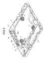
- Fig. 3 is a perspective view of the lower chassis 5
- Fig. 4 is a left-hand perspective view when the drive unit 9 is attached to the lower chassis 5
- Fig. 5 is a right-hand perspective view when the drive unit 9 is attached to the lower chassis 5.
- the lower chassis 5 is designed in a frame-shape, and three antivibration structures 11 each having a damper and a spring are secured to the lower chassis 5.
- the drive unit 9 which a clamper mechanism and a drive mechanism are integrated is mounted on the antivibration structures 11 and supported while floated.
- the drive unit 9 is equipped with a base plate 13, and a swing plate 17 which is joined to both the sides of the rear end portion of the base plate 13 through a hinge 15 and urged by a spring so as to close the tip end 17A and pinches a disc in cooperation with the base frame 13.
- a rotational plate 19 is mounted at the tip 17A of the swing plate 17, and a magnet-contained turntable 21 facing the rotational plate 19 is supported by the base plate 13. As described later, when a disc is inserted and the swing plate 17 is closed, the disc is pinched by the rotational plate 19 of the tip 17A and the turntable 21 so as to be rotatable.
- a laterally elongated disc insertion port 23 is formed at the front side of the main body 1, and a loading roller 25 which is driven by a motor 24 at the front portion of the lower chassis 5 is provided to the back side of the insertion port as shown in Fig. 2 .
- this loading roller 25 is driven by the motor 24 to pull the disc concerned into the main body 1.
- the loading roller 25 is supported by a roller support plate 27, and the base portion of the roller support plate 27 is joined to the lower chassis 5 by a hinge pin 28. Accordingly, the loading roller 25 is displaced in height position by the swing motion of the roller support plate 27.
- a trigger plate 31 is freely swingably supported at the left rear portion of the upper surface of the drive unit 9 through a support pin 30.
- the trigger plate 31 is urged in a counterclockwise direction by a spring 31S, and two pawl portions 32 and 33 which are bent to the inside of the drive unit 9 are integrally formed at one end 31a of the trigger plate 31.
- An 8-cm disc which is pulled in can abut against one pawl portion 32, and a 12-cm disc which is pulled in can abut against the other pawl potion.
- the other end 31B of the trigger plate 31 extends to the outside of the drive unit 9, and is bent downwardly along the outer wall of the drive unit 9.
- the other end 31B abuts against the rear surface 35K of a trigger 35 disposed on the lower chassis 5.
- a disc is pulled into the main body 1 and abuts against any pawl portion 32, 33 and the trigger plate 31 is counterclockwise turned, the trigger plate 31 the trigger plate 31 makes the trigger 35 move forwardly (in the direction of an arrow X).
- This trigger 35 is normally urged to the other end 31B side (in the direction of an arrow Y) by a spring (not shown).
- a part of the trigger 35 extends to the front side of the bottom portion of the lower chassis 5, and a trigger rack gear 35A is integrally formed on the upper surface of this extension portion.
- a final gear 37 (see Fig. 3 ) which is mounted on the side plate 5A of the lower chassis 5 is disposed at the front side of the trigger rack gear 35A.
- the final gear 37 is normally mounted at such a position that it is not engaged with the trigger rack gear 35A, and it is engaged with the trigger rack gear 35A only when the trigger plate 31 is turned and thus the trigger 35 moves forwardly.
- the final gear 37 is jointed to the motor 24 at the front potion of the lower chassis 5 through a gear train 38 comprising plural gears. If the trigger rack gear 35A and the final gear 37 are temporarily engaged with each other at the driving time of the motor 24, the trigger 35 moves forwardly by the driving force of the final gear 37 and the motor 24.
- a trigger cam 41 is integrally joined to the trigger 35.
- the trigger cam 41 extends inside the gear train 38 in parallel to the gear train 38, and a cam face 41A whose front portion is gradually stepwise higher is formed on the upper surface of the middle portion of the trigger cam 41.
- An upwardly-climbing stepwise slope groove 41B which guides the driving shaft 25A (see Fig. 2 ) of the loading roller 25 is formed at the tip portion of the trigger cam 41.
- a part 17B of the swing plate 17 of the drive unit 9 abuts against the cam face 41A.
- the driving shaft 25A of the loading roller 25 moves to a low position along the slope groove 41B, and the loading roller 25 is displaced to a lower position by the swinging motion of the roller support plate 27, so that the loading roller 25 is separated from the lower surface of the disc under clamping. Under this state, the turntable 21 is rotated to reproduce the disc.
- the driving shaft 25A of the loading roller 25 gradually moves to a higher position along the slope groove 41B, and at the backward-movement limit position, the loading roller 25 is displaced to a high position until it comes into contact with the lower surface of the disc by the swing motion of the roller support plate 27. Then, the disc is ejected by the loading roller 25. After the disc is ejected, the display player is set to a loading standby state. Under the eject or loading standby state, the drive unit 9 is locked to the chassis 3 by a lock mechanism described next.
- This lock mechanism comprises two mechanisms of a first lock mechanism and a second lock mechanism.
- Figs. 6 and 7 show the lock state of the first lock mechanism
- Figs. 8 and 9 shows the unlock state of the first lock mechanism.
- Fig. 10 shows the lock state of the second lock mechanism
- Fig. 11 shows the unlock state of the second lock mechanism.
- the first lock mechanism 250 is constructed by supporting a gear plate 92 on the bottom plate of the lower chassis 5 through a pin 91.
- One end of a spring 93 is joined to the fixed end 92A of the gear plate 92, and the other end of the spring 93 is joined to the fixed portion 5K of the lower chassis 5.
- Two different cam holes 94, 194 are formed in the lower chassis 5 and the gear plate 92, and a pin 95 of a sub lock plate 98 is fitted in the cam hole 94 of the gear plate 92.
- a pin 197 of a lock plate 96 is fitted in the cam hole 194.
- the gear plate 92 is supported so as to be freely rotatable around the pin 91, and also urged in a counterclockwise direction by a spring 93 at all times.
- a gear 92G is integrally formed on the outer periphery of the gear plate 92, and the gear 92G is engaged with a rack gear 41R which extends in the forward and backward direction of the drive unit 9 and is formed on the inner surface of the bottom portion of the trigger cam 41 described above.
- the lock plate 96 reciprocates in the right-and-left direction (the direction of an arrow Q) interlockingly with the swing operation of the gear plate 92.
- the lock plate 96 has a left end 96A, a lower end 96B and an upper end 96C in Fig. 6 , and as shown in Fig. 7 , it is equipped with lock pieces 96D, 96F which are bent and upwardly clinched and erected and an arcuate hole 96E.
- the lock piece 96D freely intrudes into a groove 99A of a fixed piece, and the fixed piece 99 is fixed to a base plate 13 (see Fig. 10 ) of the drive unit 9.
- the lock piece 96F freely intrudes into a fixed piece 13X (see Fig. 11 ) , and the fixed piece 13F is formed integrally with the base plate 13.
- a pin 97 is loosely fitted in the arcuate hole 96E.
- the pin 97 is fixed to the gear plate 92 so as to extend upwardly and the upper end thereof is loosely fitted in an elongated hole 98A of the sub lock plate 98.
- the sub lock plate 98 extends in the same direction as the lock plate 96 above the lock plate 96.
- a pin 197 of the lock plate 96 is fitted in the cam hole 194 of the gear plate 92, and the pin 95 of the sub lock plate 98 is fitted in the cam hole 94.
- the lock plate 96 and the sub lock plate 98 reciprocates in the direction of the arrow Q in Fig. 6 .
- a through hole 35M is formed at the lower portion of the trigger 35, a fork pawl 211 is fitted in the through hole 35M, and the fork pawl 211 is formed integrally with the base plate 13 as not shown. Accordingly, when the trigger 35 moves forwardly, the fork pawl 211 is separated from the through hole 35M. When the trigger 35 backs away to a retract limit position, the fork pawl 211 is fitted in the through hole 35M, and thus the drive unit 9 is set to the lock state.
- the fork pawl 211 is fitted in the through hole 35M, the lock piece 96D is fitted into the groove 99A of the fixed piece 99 and the lock piece 96F is fitted to the fixed piece 13X, whereby the drive unit is locked at three points.
- the second lock mechanism 260 is located at the opposite side to the first lock mechanism 250, and disposed in the drive unit 9. That is, the second lock mechanism 260 comprises a cam member 111 and a lock member 121.
- the cam member 111 is freely rotatably mounted on the base plate 13 of the drive unit 9 by a pin 112, and gears 111A and 111B are integrally formed at the base end and free end of the cam member 111, respectively.
- the gear 111A at the base end is engaged with a gear 113 formed on the swing plate 17 of the drive unit 9, and the gear 111B at the free end is engaged with a gear 121A of the lock member 121.
- the lock member 121 is freely rotatably mounted on the base plate 13 by a pin 122, and the free end 121B thereof is projected from an opening 123 formed in the swing plate 17 of the drive unit 9. Under this state, the free end 121B projecting upwardly from the opening 123 abuts against the back surface of the upper chassis 7 (not shown), and the base end 121C extending to the back side of the free end 121B abuts against the lower chassis 5 (not shown), whereby the drive unit 9 is locked to the upper chassis 7 and the lower chassis 5. Furthermore, when the free end 121B and the base end 121C are set to a turn-down state ( Fig. 11 ), the lock is released.
- the lock operation or unlock operation of the lock mechanism is carried out interlockingly with the operation of the trigger 35 and the trigger cam 41.
- the first lock mechanism 250 and the second lock mechanism 260 are locked with a time lag, and unlocked with a time lag.
- the lock piece 96D is not fitted in the groove 99A of the fixed piece as shown in Figs. 8 and 9 .
- the free end 121B of the lock member 121 is turned down and it is not projected from the opening 123 of the swing plate 17 as shown in Fig. 11 .
- the trigger 35 and the trigger cam 41 are located at the forward-movement limit position.
- the swing plate 17 of the drive unit 9 pinches the disc, it is closed by a magnet and a spring force, the drive unit 9 is supported through the three antivibration structures 11 while floated, and thus the disc can be reproduced while rotated.
- the tip 17A of the swing plate 17 is gradually opened from the state of Fig. 11 to the state of Fig. 10 .
- the cam member 111 is engaged with the gear 113 of the swing plate 17 and swung in the direction of the arrow A.
- the lock member 121 is swung in the direction of the arrow B through the gear 111B and the gear 121A, and the free end 121B thereof is projected from the opening 123 of the swing plate 17.
- the projected free end 121B abuts against the back surface of the upper chassis (not shown), the base end 121C abuts against the lower chassis 5 (not shown), the second lock mechanism 260 functions, and the drive unit 9 is locked to the upper chassis 7 and the lower chassis 5.
- the trigger cam 41 is allowed to reciprocate in the forward and backward direction of the drive unit 9, and the lock plate 96 interlocked with the reciprocating operation of the trigger cam 41 is allowed to reciprocate in the right-and-left direction of the drive unit 9. Therefore, even when force acts on the lock piece 96D so as to separate the lock piece 96D from the groove 99A of the fixed piece 99, the acting direction of this force is perpendicular to the operating direction of the trigger cam 41 and thus this force does not contribute to the reciprocating operation of the trigger cam 41. Accordingly, even when unintentional force acts on the lock piece 96 so as to make the lock piece 96D escape from the groove 99A of the fixed piece 99, the lock is not released, and the lock state of the drive unit 9 is sufficiently self-held.
- the driving mechanism comprising the trigger 35, the trigger cam 41, the gear train 38, etc. is disposed at one side of the drive unit 9, and the first lock mechanism 250 is disposed at the same side. Therefore, as compared with a case where they are disposed at both the sides, the space can be saved, and the disc player can be miniaturized.
- the lock state is equivalent to a so-called both-side lock state by a simple construction, and the best lock state can be obtained.
- the lock member 121 of the second lock mechanism 260 rises and falls interlockingly with the opening/closing operation of the swing plate 17. Therefore, an extra actuator for making the lock member 121 rises and falls is unnecessary, and thus the second lock mechanism 260 can be operated with a simple construction.
- the pair of gate members 59 which come into contact with the outer peripheral portion of the inserted disc and evacuated to the side of the insertion port 23 are provided at the insertion port 23 of the disc.
- the gate members 59 are provided with the pair of turn plates 62, 63 which are disposed so as to be divided to both the sides with respect to the center of the insertion port 23, and as shown in Fig. 12 , these turn plates 62, 63 are joined to the outer surfaces of the front portion of the upper chassis 7 through pins (support members) 64, 65.
- the turn plates 62, 63 are urged in the closing direction (the direction of the arrow A) by springs 60, 61, and a pair of gate pins 67, 68 which face the insertion port 23 are secured to the turn plates 62, 63.
- Slide holes 62A, 63A are formed at the base portions of the turn plates 62, 63, and pins 71, 72 which are fitted in these slide holes 62A, 63A are secured to a joint plate 73.
- the base portions of the turn plates 62, 63 are joined to each other through the joint plate 73.
- a pair of guide holes 74, 75 extending in the insertion direction (the direction of the arrow Z) of the disc are formed in the joint plate 73, and guide portions 76, 77 fitted in the guide holes 74, 75 are formed by cutting and upwardly erecting a part of the upper chassis 7 and then bending the part horizontally. These erected slender portions are fitted in the guide holes 74, 75.
- 78 represents a plate secured to the upper chassis 7, and the plate 78 functions as a stopper in the closing direction of the turn plates 62, 63.
- the disc When the disc is inserted into the insertion port 23, the disc pushes out the gate pins 67, 68 to the sides.
- the outer peripheral portion 100A of the disc 100 pushes out the pair of gate pins 67, 68 to the sides of the insertion port 23 as shown in Fig. 13 , and the turn plates 62, 63 are swung in the opening direction (the direction of the arrow B).
- the pins 71, 72 move in the slide holes 62A, 63A, whereby the joint plate 73 reciprocates in the disc insertion direction (the direction of an arrow Z) along the guide portions 76, 77 interlockingly with the swing motion of the turn plates 62, 63.
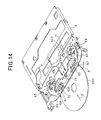
- Fig. 14 is a perspective view when a small disc 200 of 8cm in diameter is inserted.
- the disc diameter is smaller than the width of the insertion port 23, and thus there is a risk that the disc is inserted while displaced to one end of the insertion port 23.
- the other gate pin 68 is hardly pushed out, and only one pin 67 is pushed out.
- only the turn plate 62 at the side of one gate pin 67 is swung in the opening direction (the direction of the arrow B).
- the other turn plate 63 is not opened.
- the joint plate 73 is not turned at the pin 72 side, and it is turned at only the pin 71 side. In this case, the joint plate 73 is inclined.
- Fig. 15 is a perspective view when the upper chassis 7 is viewed from the back side.
- Guide bars (guide mechanism) 81, 82 extending on two lines are provided to the inner surface of the upper chassis 7 so as to project to the lower side (to the side facing the loading roller 25) when the upper chassis 7 is assembled and downwardly (upwardly) guides a disc inserted into the insertion port 23.
- These guide bars 81, 82 extend in parallel to each other in the side direction of the insertion port 23, and each of the guide bars 81, 82 is gradually increased in height to the end of the insertion port 23.
- the front-side guide bar 81 is designed so that the height of the projection portion 81A thereof is gradually increased in height from a position nm near to the center
- the back-side guide bar 82 is designed so that the height of the projection portion 82A thereof is gradually increased from a position n which is more displaced to the end than the position m.
- the loading roller 25 confronts the pair of guide bars 81, 82, and the disc is loaded while pinched by the roller 25 and the guide bars 81, 82.
- Fig. 16 is a cross-sectional view when the disc 200 of 8cm in diameter is inserted
- Fig. 17 is a perspective view of Fig. 16
- Fig. 18 is a cross-sectional view when the disc 100 of 12cm in diameter is inserted
- Fig. 19 is a perspective view of Fig. 18 .
- the disc 200 inserted from the insertion port 23 is pinched between the loading roller 25 and the lower projecting portions 81A, 82A of the guide bars 81, 82, and loaded to the back side of the main body 1 along a first loading passage RK located at a high place in the main body 1.
- a first disc contact portion 83 is located at the terminal portion of the first loading passage RK1, and the disc 200 is brought into contact with the first disc contact portion 83 and stopped.
- the disc 200 pushes and moves the pawl portion 32 of the trigger plate 31 as shown in Fig. 17 , and the clamp operation of the disc 200 is executed as described above with this push and movement as a trigger.
- a guide bar 331 is formed so as to come into contact with the outer periphery (the right back side of Fig. 13 ) of the disc 100 of 12cm in diameter.
- the guide bar 331 is mounted so as to be swingable around a pin 310, and is urged clockwise around the pin 310 through a spring 312. As shown in Fig.
- a backwardly-declined tapered face 313 is formed on the lower surface of the free end of the guide bar 331.
- the tip 100A of the disc 100 is oriented to the lower side along the tapered face 313, and crosses the pawl portion 32 of the trigger plate 31.
- the guide bar 331 is counterclockwise turned around the pin 310, and stable loading is executed while the outer periphery of the disc 100 is guided by the guide bar 331.
- a second disc contact portion 84 is located at the terminal portion of a second loading passage RK2. The disc 100 comes into contact with the second disc contact portion 84 and stops there.
- the disc 100 pushes and moves the pawl portion 33 of the trigger plate 31 as shown in Fig. 19 , and the clamp operation of the disc 100 is executed as described above with this push and movement as a trigger.
- the projection 314 of the lower surface of the guide bar 331 is fitted into a recess (not shown) of the swing plate 17 side, and the guide bar 331 is separated from the outer periphery of the disc 100, and fixed. Accordingly, the guide bar 331 is prevented from coming into contact with the disc 100 at the play time.
- the different loading passages RK1 and RK2 are separately formed at the upper and lower sides in the main body 1. Therefore, it is unnecessary that a complicated mechanism for holding discs different in size is provided at the terminal portion of the loading passage as in the case of the prior art, and thus the apparatus can be designed to be thin. Furthermore, this construction may be applied to a disc player for loading discs different in material or the like. In this case, if the loading passage is improved in accordance with the material or the like, a disc player in which discs are not scratched can be provided.
- a disc player for reproducing information of a recording medium disc such as CD (compact disc), DVD (digital versatile disc) or the like is equipped with a drive unit for chucking a disc on a turn table and rotating the turn table under this state to thereby rotate the disc, and a pickup driving mechanism for sliding a pickup for reading information from the rotated disc in the radial direction of the disc.
- the conventional construction has a problem that a part of the rack member is deformed (creep-deformation) by the urging force of an elastic member or the part is broken. Therefore, there has been also desired a mechanism in which the fitting state between the groove of the lead screw and the projection of the rack member is kept excellent and the creep deformation of the rack member by the urging force of the elastic member is prevented.
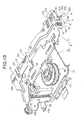
- an opening portion M is formed in the base plate 13 of the drive unit 9 as shown in Fig. 20 , and a pickup driving portion (support member driving mechanism, pickup driving mechanism) 103 for driving a pickup 102 in the radial direction of the disc (in the direction of P in Fig. 20 )is disposed in the opening portion M.
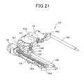
- the pickup driving portion 103 is equipped with a lead screw 104 provided along the radial direction of the disc, two guide shafts 105, 106 disposed substantially in parallel to the lead screw 104, and a pickup optical part support member 114 which is suspended between the guide shafts 105 and 106 and freely slidable along the axial direction of the guide shafts 105, 106 by the rotation of the lead screw 104.
- a stepping motor 116 for rotating the lead screw 104 is directly joined to one end of the lead screw 104 as shown in Fig. 21 , and the other end thereof is freely rotatably supported by a bearing portion 116B formed in the base frame 116A. Furthermore, the guide shafts 105, 106 are supported by bearing portions (not shown) formed at the lower surface side of the base plate 13.
- the pickup optical part support member 114 is equipped with a base portion 114A on which the pickup 102 is mounted.
- a first bearing portion 114B having an insertion hole 120 in which the guide shaft 105 is inserted is provided to one end side of the base portion 114A, and a second bearing portion 114C having a substantially U-shaped section in which the guide shaft 106 is fitted is provided to the other end side of the base portion 114A.
- a rack member 115 and a leaf spring 107 for urging a gear portion 115B (described later) of the rack member 115 to the lead screw 104 are arranged at the first bearing portion 114B of the pickup optical part support member 114 while overlapped with each other, and the rack member 115 and the leaf spring 107 are fixed to the first bearing portion 114B by a screw 122.
- the rack member 115 is equipped with a resin rack member main body (support member) 115A and a gear portion 115B disposed at the front surface side of the rack member main body 115A, and plural (two in this embodiment) first projections 131 which are engaged with the lead screw 104 are formed on the front surface of the gear portion 115B. Second projections 132 are formed on the front surface of the rack member main body 115A so as to be aligned with the projections 131. As shown in Fig. 23 , the lower end of the gear portion 115B is joined to the rack member main body 115A through a thin portion 115C.
- the rack member 115 is formed of resin so as to be integrally provided with the rack member main body 115A and the gear portion 115B, and the gear portion 115B is constructed to be freely tilted through the thin portion 115C.
- the first projections 131 formed on the gear portion 115B function as movable teeth
- the second projections 132 formed on the rack member main body 115A function as fixed teeth.
- the leaf spring 107 is equipped with a flat plate portion 107A fixed to the rack member main body 115A, and a spring portion 107B which is provided continuously with the flat plate portion 107A and bent in a substantially L-shape in section.
- the tip portion of the spring portion 107B is provided with a contact portion 107C which is formed by bending the tip portion substantially vertically inwardly, and the contact portion 107C is fitted in a recess portion 133 ( Fig. 23 ) formed on the back surface of the gear portion 115B.
- the spring portion 107B is provided with regulating portions 107D which are fitted to the rack member main body 115A to regulate the tilt angle of the gear portion 115B when the gear portion 115B is tilted through the thin portion 115C by the urging force of the leaf spring 107.
- the regulating portions 107D extend from both the side ends of the contact portion 107C, and are formed to be larger than the width of the gear portion 115B. As shown in Fig.
- groove portions 135 in which the regulating portions 107D of the leaf spring 107 are mounted are formed in the rack member main body 115A, and when the gear portion 115B is tilted through the thin portion 115C, regulating portions 121D abut against the front surfaces 135A of the groove portions 135, thereby regulating the tilt angle of the gear portion 115B.
- the drive unit 9 for rotating the disc, the pickup 102 for reading out a signal from the rotating disc and the pickup driving portion 103 for sliding the pickup 102 in the radial direction of the disc are provided, and the pickup driving portion 103 is equipped with the lead screw 104 disposed along the radial direction of the disc, the guide shafts 105, 106 disposed in parallel to the lead screw 104, the pickup optical part support member 114 which is mounted on the guide shafts 105, 106 so as to be freely movable in the axial direction and on which the pickup 102 is mounted, the resin rack member main body 115A joined to the pickup optical part support member 114, the gear portion 115B which is provided to the rack member main body 115A so as to be freely tilted through the thin portion 115C and engaged with the lead screw 104, and the leaf spring 107 which is provided to the rack member main body 115A and urges the gear portion 115B to the lead screw 104.
- the leaf spring 107 is provided with the regulating portions 107Dwhich are fitted to the rack member main body 115A and regulate the tilt angle of the gear portion 115B. Therefore, the regulating portions 107D prevent the gear portion 115B from being tilted through the thin portion 115C by a predetermined angle or more, and the creep deformation of the thin portion 115C due to the tilt of the gear portion 115B can be prevented. Furthermore, the creep deformation by the leaf spring 107 can be suppressed to the minimum level, and thus the assemble work of the pickup driving portion 103 can be easily performed.
- the leaf spring 107 has the contact portion 107C which comes into contact with the back surface of the gear portion 115B, and the regulating portions 107D are formed at both the side edges of the contact portion 107C. Therefore, the shape of the leaf spring 107 is simplified, and the leaf spring 107 can be easily formed. In addition, the work of assembling the leaf spring 107 to the rack member 115 can be made easy.
- the rack member main body 115A and the gear portion 115B are integrally formed of resin, so that the rack member 115 can be easily formed.
- Fig. 24 is an exploded perspective view showing the rack member 151
- Fig. 25 is a perspective view showing the cross-section of the rack member 151.
- the constructions other than the rack member 151 are the same as described above, and thus the description thereof is omitted.
- the rack member 151 is equipped with a rack member main body (support member) 151A formed of resin, and a gear portion 151B disposed at the front surface side of the rack member main body 151a.
- Plural (two in this embodiment) projections 161 which are engaged with the lead screw 104 are formed on the front surface of the gear portion 151B.
- Second projections 162 which are aligned with the projections 161 are formed on the front surface of the rack member main body 151A.
- the first projections 161 formed on the gear portion 151B function as movable teeth
- the second projections 162 formed on the rack member main body 151A function as fixed teeth.
- the lower end of the gear portion 151B is joined to the rack member main body 151A through the thin portion 151C. That is, the rack member 151 is integrally formed so as to have the rack member main body 151A and the gear portion 151B, and the gear portion 151B is constructed so as to be freely tilted through the thin portion 151C.
- a space P is formed between the rack member main body 151A and the gear portion 151B, and a coil spring 155 for urging the gear portion 151 to the lead screw 104 is accommodated in this space P.
- One end 155A of the coil spring 155 comes into contact with the front surface 152 of the rack member main body 151A forming the space P, and the other end 155B thereof is fitted in the recess portion 153 formed on the back surface of the gear portion 151B.
- regulating portions 151D extending from both the side ends of the gear portion 151B of the rack member 151 are formed in the rack member 151, and also groove portions 163 in which the regulating portions 151D are mounted are formed in the rackmember main body 151A.
- the drive unit 9 for rotating the disc, the pickup 102 for reading the signal from the rotating disc, and the pickup driving portion 103 for sliding the pickup 102 in the radial direction of the disc are provided, and the pickup driving portion 103 is equipped with the lead screw 104 disposed along the radial direction of the disc, the guide shafts 105, 106 disposed in parallel to the lead screw 104, the pickup optical part support member 114 which is mounted on the guide shafts 105, 106 so as to be freely movable in the axial direction and on which the pickup 102 is mounted, the rack member main body 151A of resin which is joined to the pickup optical part support member 114, the gear portion 151B which is provided to the rack member main body 151A so as to be freely tilted through the thin portion 151C and engaged with the lead screw 104, and the coil spring 155 which is provided to the rack member main body 151A and urges the gear portion 151B to the lead screw 104.
- the gear portion 151B is provided with the regulating portions 151D which are fitted to the rack member main body 151A to regulate the tilt angle of the gear portion 151B, whereby the regulating portions 151D prevent the gear portion 151B from being tilted through the thin portion 151C by a predetermined angle or more, and the creep deformation of the thin portion 151C due to the tilt of the gear portion 151 can be prevented. Furthermore, the creep deformation by the coil spring 155 can be suppressed to the minimum level, and thus the assembling work of the pickup driving portion 103 can be easily performed.
- the rack member main body 151A and the gear portion 151B are integrally formed of resin, and thus the rack member 151 can be easily formed.
- the driving mechanism for the support member is applied to the mechanism for driving the pickup of the disc player.
- the present invention is not limited to this embodiment.
- the driving mechanism may be applied to a mechanism for driving a head of a printer, or a mechanism for driving a movable lens of a camera such as a zooming lens, a focus lens or the like.
Landscapes
- Feeding And Guiding Record Carriers (AREA)
Abstract
Description
- The present invention relates to a disc player that is mounted in a vehicle and reproduces information of a recording medium disc such as CD (compact disc), DVD (digital versatile disc) or the like.
- A conventional disc player supports a drive unit inside a chassis while floating the drive unit, and loads a disc to the drive unit to reproduce the disc. In addition, at least at a disc eject or loading standby time, the disc player releases the floating of the drive unit and locks the drive unit to the chassis (for example, see Patent Document 1).
Patent Document 1:WO/2001/091119 - Various proposals have been made for this type of lock mechanism. In the conventional proposals, the structure is complicated, the number of parts is increased and the cost is increased. In addition, the thickness of the disc player is increased because the structure concerned is contained in the disc player.
Furthermore, this type of lock mechanism is required to be provided with a function of self-holding the lock state when an impact is applied to the chassis. Various proposals have been hitherto made to secure this function, however, these proposals complicate the structure and increase the cost. - Therefore, an object of the present invention is to solve the problem of the conventional techniques described above, and provide a disc player which can be reduced in the number of parts and in cost by making the construction thereof simpler than the conventional ones and also designed to be thinner. Furthermore, the present invention has an object to provide a disc player that is provided with a function of sufficiently self-holding a lock state.
- According to the present invention, a disc player in which a drive unit is supported inside a chassis while floating the drive unit and a disc is loaded to the drive unit to reproduce the disc and which is provided with a lock mechanism for releasing the floating of the drive unit at least under a disc eject or loading standby state to lock the drive unit to the chassis, is characterized in that the drive unit comprises a base plate and a swing plate for pinching the disc in cooperation with the base plate, the lock mechanism is disposed between the base plate and the swing plate, and the operation of the lock mechanism is interlocked with the operation of the swing plate.
- In this construction, the operation of the lock mechanism is interlocked with the operation of the swing plate. Therefore, an extra actuator or the like for operating the lock mechanism is unnecessary, so that the construction can be simplified, the number of parts can be reduced and the cost can be reduced Furthermore, the structure is simplified, and thus the thickness of the disc player can be reduced.
- In this case, the lock mechanism may be unlocked interlockingly with a closing operation of the swing plate. Furthermore, the lock mechanism comprises a cam member and a lock member, the cam member is mounted on the base plate so as to be freely rotatable, gears are formed integrally with a base end and a free end of the cam member, the gear at the base end is engaged with a gear formed on the swing plate, the gear at the free end is engaged with a gear of the lock member, the lock member is freely rotatably mounted on the base plate, a free end of the lock member is projected from an opening formed in the swing plate, the free end is brought into contact with the back surface of the chassis to be locked, and the free end is turned down interlockingly with the closing operation of the swing plate. Furthermore, the lock mechanism may be disposed at one side of the drive unit.
- In this construction, the lock member of the lock mechanism is turned down interlockingly with the opening/closing operation of the swing plate, so that an extra actuator for erecting the lock member is unnecessary and the lock mechanism can be operated with a simple construction.
- In this construction, another lock mechanism is mounted in the drive unit so as to be disposed on the chassis and reciprocable in the forward and backward direction of the drive unit, the other lock mechanism is equipped with a trigger cam having a rack gear, a gear plate which is engaged with the rack gear of the trigger cam and swung interlockingly with the reciprocating motion of the trigger cam, a lock plate which reciprocates in the right-and-left direction of the drive unit interlockingly with the swing operation of the gear plate, and a lock piece provided to the lock plate, the trigger cam is moved in the forward and backward direction, the lock plate is reciprocated in the right-and-left direction to fit a fixed piece fixed to the drive unit into a groove, and the drive unit is locked to the chassis.
- In this construction, the trigger cam can reciprocate in the forward and backward direction of the drive unit, the lock plate interlocked with the reciprocating operation of the trigger cam can reciprocate in the right-and-left direction of the drive unit. Therefore, even when force acts on the lock piece so as to make the lock piece escape from the groove of the fixed piece, the acting direction of the force is perpendicular to the operating direction of the trigger cam and thus this force does not contribute to the reciprocating operation of the trigger cam. Accordingly, unintentional force acts on the lock piece so as to make the lock piece escape from the groove of the fixed piece, the lock is not released, and the lock state of the drive unit is sufficiently self-held.
- In this case, the rack gear may extend in the forward and backward direction of the drive unit. Furthermore, the other lock mechanism may be disposed at one side of the drive unit. Still furthermore, the other lock mechanism may be unlocked interlockingly with the closing operation of the swing plate.
- In the present invention, the operation of the lock mechanism is interlocked with the operation of the swing plate. Therefore, an extra actuator for operating the lock mechanism or the like is unnecessary. Therefore, the construction can be simplified, the number of parts can be reduced and the cost can be reduced. Furthermore, the structure can be simplified, and thus the thickness of the disc player can be reduced.
- Furthermore, in the present invention, the trigger cam can reciprocate in the forward and backward direction of the drive unit, the lock plate interlocked with the reciprocating operation of the trigger cam can reciprocate in the right-and-left direction of the drive unit. Therefore, even when force acts on the lock piece so as to make the lock piece escape from the groove of the fixed piece, the acting direction of the force is perpendicular to the operating direction of the trigger cam and thus this force does not contribute to the reciprocating operation of the trigger cam. Accordingly, unintentional force acts on the lock piece so as to make the lock piece escape from the groove of the fixed piece, the lock is not released, and the lock state of the drive unit is sufficiently self-held.
-
- [
Fig. 1 ] is a perspective view showing a first embodiment of a disc player according to the present invention. - [
Fig. 2 ] is a perspective view when an upper chassis is detached; - [
Fig. 3 ] is a perspective view of a lower chassis. - [
Fig. 4 ] is a left-hand perspective view when a drive unit is secured to the lower chassis. - [
Fig. 5 ] is a right-side perspective view when the drive unit is secured to the lower chassis. - [
Fig. 6 ] is a plan view showing a lock state of a first lock mechanism. - [
Fig. 7 ] is a perspective view showing the lock state of the first lock state. - [
Fig. 8 ] is a plan view showing an unlock state of the first lock mechanism. - [
Fig. 9 ] is a perspective view showing the unlock state of the first lock mechanism. - [
Fig. 10 ] is a perspective view showing the lock state of a second lock mechanism. - [
Fig. 11 ] is a perspective view showing an unlock state of the second lock mechanism. - [
Fig. 12 ] is a perspective view showing a pair of gate members. - [
Fig. 13 ] is a perspective view showing a state under which the gate members are opened by a 12cm disc. - [
Fig. 14 ] is a perspective view showing a state under which the gate members are opened by an 8cm disc. - [
Fig. 15 ] is a perspective view when the upper chassis is viewed from the back side. - [
Fig. 16 ] is a cross-sectional view when the 8cm disc is inserted. - [
Fig. 17 ] is a perspective view ofFig. 16 . - [
Fig. 18 ] is a cross-sectional view when the 12cm disc is inserted. - [
Fig. 19 ] is a perspective view ofFig. 18 . - [
Fig. 20 ] is a plan view when the drive unit is secured to the lower chassis. - [
Fig. 21 ] is a perspective view of a pickup driving unit. - [
Fig. 22 ] is an exploded perspective view of a rack member. - [
Fig. 23 ] is a perspective view showing the cross-section of the rack member. - [
Fig. 24 ] is an exploded perspective view of the rack member according to a modification example. - [
Fig. 25 ] is a perspective view showing the cross-section of the rack member. -
- 1
- main body
- 3
- chassis
- 5
- lower chassis
- 7
- upper chassis
- 9
- drive unit
- 13
- base plate
- 17
- swing plate
- 23
- insertion port
- 41
- trigger cam
- 41R
- rack gear
- 92
- gear plate
- 92G
- gear
- 96
- lock plate
- 96D
- lock piece
- 99
- fixed piece
- 99A
- groove
- 111
- cam member
- 121
- lock member
- 121
- free end
- 250
- first lock mechanism
- 260
- second lock mechanism
- A first embodiment of the present invention will be described with reference to the drawings.
Fig. 1 is a perspective view showing the outlook of a disc player according to an embodiment of the present invention. Recording discs which are different in size, for example, 8cm, 12cm, etc. in diameter such as CD, DVD or the like are pulled into this disc player, and information recorded in the discs is reproduced. 1 represents a main body, and the main body 1 is equipped with a metal chassis. Thechassis 3 is equipped with alower chassis 5 and an upper chassis covering the upper side of thelower chassis 5. As omitted fromFig. 1 , a loading mechanism for loading a disc, a clamper mechanism for clamping the disc, a drive mechanism for driving the disc, etc. are provided in thechassis 3. -
Fig. 3 is a perspective view when theupper chassis 7 is detached,Fig. 3 is a perspective view of thelower chassis 5,Fig. 4 is a left-hand perspective view when thedrive unit 9 is attached to thelower chassis 5, andFig. 5 is a right-hand perspective view when thedrive unit 9 is attached to thelower chassis 5. - As shown in
Fig. 3 , thelower chassis 5 is designed in a frame-shape, and threeantivibration structures 11 each having a damper and a spring are secured to thelower chassis 5. As shown inFig. 2 , thedrive unit 9 which a clamper mechanism and a drive mechanism are integrated is mounted on theantivibration structures 11 and supported while floated.
As shown inFigs. 4 and5 , thedrive unit 9 is equipped with abase plate 13, and aswing plate 17 which is joined to both the sides of the rear end portion of thebase plate 13 through ahinge 15 and urged by a spring so as to close thetip end 17A and pinches a disc in cooperation with thebase frame 13. Arotational plate 19 is mounted at thetip 17A of theswing plate 17, and a magnet-containedturntable 21 facing therotational plate 19 is supported by thebase plate 13. As described later, when a disc is inserted and theswing plate 17 is closed, the disc is pinched by therotational plate 19 of thetip 17A and theturntable 21 so as to be rotatable. - As shown in
Fig. 1 , a laterally elongateddisc insertion port 23 is formed at the front side of the main body 1, and aloading roller 25 which is driven by amotor 24 at the front portion of thelower chassis 5 is provided to the back side of the insertion port as shown inFig. 2 .
When the disc is detected, thisloading roller 25 is driven by themotor 24 to pull the disc concerned into the main body 1. Theloading roller 25 is supported by aroller support plate 27, and the base portion of theroller support plate 27 is joined to thelower chassis 5 by ahinge pin 28. Accordingly, theloading roller 25 is displaced in height position by the swing motion of theroller support plate 27. - A
trigger plate 31 is freely swingably supported at the left rear portion of the upper surface of thedrive unit 9 through asupport pin 30. Thetrigger plate 31 is urged in a counterclockwise direction by aspring 31S, and twopawl portions drive unit 9 are integrally formed at one end 31a of thetrigger plate 31. An 8-cm disc which is pulled in can abut against onepawl portion 32, and a 12-cm disc which is pulled in can abut against the other pawl potion. Theother end 31B of thetrigger plate 31 extends to the outside of thedrive unit 9, and is bent downwardly along the outer wall of thedrive unit 9. Theother end 31B abuts against therear surface 35K of atrigger 35 disposed on thelower chassis 5. When a disc is pulled into the main body 1 and abuts against anypawl portion trigger plate 31 is counterclockwise turned, thetrigger plate 31 thetrigger plate 31 makes thetrigger 35 move forwardly (in the direction of an arrow X). Thistrigger 35 is normally urged to theother end 31B side (in the direction of an arrow Y) by a spring (not shown). - As shown in
Fig. 4 , a part of thetrigger 35 extends to the front side of the bottom portion of thelower chassis 5, and atrigger rack gear 35A is integrally formed on the upper surface of this extension portion. A final gear 37 (seeFig. 3 ) which is mounted on theside plate 5A of thelower chassis 5 is disposed at the front side of thetrigger rack gear 35A. Thefinal gear 37 is normally mounted at such a position that it is not engaged with thetrigger rack gear 35A, and it is engaged with thetrigger rack gear 35A only when thetrigger plate 31 is turned and thus thetrigger 35 moves forwardly. As shown inFig. 2 , thefinal gear 37 is jointed to themotor 24 at the front potion of thelower chassis 5 through agear train 38 comprising plural gears. If thetrigger rack gear 35A and thefinal gear 37 are temporarily engaged with each other at the driving time of themotor 24, thetrigger 35 moves forwardly by the driving force of thefinal gear 37 and themotor 24. - As shown in
Fig. 4 , atrigger cam 41 is integrally joined to thetrigger 35. Thetrigger cam 41 extends inside thegear train 38 in parallel to thegear train 38, and acam face 41A whose front portion is gradually stepwise higher is formed on the upper surface of the middle portion of thetrigger cam 41. An upwardly-climbingstepwise slope groove 41B which guides the drivingshaft 25A (seeFig. 2 ) of theloading roller 25 is formed at the tip portion of thetrigger cam 41. Apart 17B of theswing plate 17 of thedrive unit 9 abuts against thecam face 41A.
After thetrigger 35 engages with thefinal gear 37 and moves to the stroke end, thetrigger cam 41 is pushed out, the rack of thetrigger cam 41 engages with thefinal gear 37 and thetrigger cam 41 moves forwardly (in the direction of the arrow X). - When the
trigger cam 41 moves forwardly (in the direction of the arrow X), thecam face 41A with which thepart 17B concerned is in contact is gradually lowered, and theswing plate 17 is swung in the closing direction by the spring force. When thetrigger cam 41 further moves forwardly and thus moves to the forward movement limit position, thepart 17B is completely separated from thecam face 41A, and clamping of the disc by therotational plate 19 of the tip of theswing plate 17 and theturntable 21 is completed. At the same time, by the release of the fitting between thepart 17B of theswing plate 17 and thecam face 41A, thedrive unit 9 is completely floated and supported through the threeantivibration structures 11. At the same time, the drivingshaft 25A of theloading roller 25 moves to a low position along theslope groove 41B, and theloading roller 25 is displaced to a lower position by the swinging motion of theroller support plate 27, so that theloading roller 25 is separated from the lower surface of the disc under clamping. Under this state, theturntable 21 is rotated to reproduce the disc. - When the
motor 24 is reversely rotated, thetrigger 35 and thetrigger cam 41 move backwardly (in the direction of the Y arrow) through thegear train 38, thefinal gear 37 and thetrigger rack gear 35A. In connection with this movement, thecam face 41A with which thepart 17B concerned is in contact is gradually higher, and theswing plate 17 is pushed up against the spring force and swung in the opening direction. Furthermore, when thetrigger 35 and thetrigger cam 41 further backwardly move and thetrigger cam 41 moves to the backward-movement limit position , thepart 17B runs upon the highest position of thecam face 41A, and a disc inserting gap is formed between therotational plate 19 of the tip of theswing plate 17 and theturntable 21. - At the same time, the driving
shaft 25A of theloading roller 25 gradually moves to a higher position along theslope groove 41B, and at the backward-movement limit position, theloading roller 25 is displaced to a high position until it comes into contact with the lower surface of the disc by the swing motion of theroller support plate 27. Then, the disc is ejected by theloading roller 25.
After the disc is ejected, the display player is set to a loading standby state. Under the eject or loading standby state, thedrive unit 9 is locked to thechassis 3 by a lock mechanism described next. - Next, the lock mechanism of the
drive unit 9 will be described.
This lock mechanism comprises two mechanisms of a first lock mechanism and a second lock mechanism.Figs. 6 and7 show the lock state of the first lock mechanism, andFigs. 8 and9 shows the unlock state of the first lock mechanism.Fig. 10 shows the lock state of the second lock mechanism, andFig. 11 shows the unlock state of the second lock mechanism. - A shown in
Fig. 6 , thefirst lock mechanism 250 is constructed by supporting agear plate 92 on the bottom plate of thelower chassis 5 through apin 91. One end of aspring 93 is joined to thefixed end 92A of thegear plate 92, and the other end of thespring 93 is joined to the fixedportion 5K of thelower chassis 5. Two different cam holes 94, 194 are formed in thelower chassis 5 and thegear plate 92, and apin 95 of asub lock plate 98 is fitted in thecam hole 94 of thegear plate 92. Apin 197 of alock plate 96 is fitted in thecam hole 194. Thegear plate 92 is supported so as to be freely rotatable around thepin 91, and also urged in a counterclockwise direction by aspring 93 at all times.
Agear 92G is integrally formed on the outer periphery of thegear plate 92, and thegear 92G is engaged with arack gear 41R which extends in the forward and backward direction of thedrive unit 9 and is formed on the inner surface of the bottom portion of thetrigger cam 41 described above. - The
lock plate 96 reciprocates in the right-and-left direction (the direction of an arrow Q) interlockingly with the swing operation of thegear plate 92. Thelock plate 96 has aleft end 96A, alower end 96B and an upper end 96C inFig. 6 , and as shown inFig. 7 , it is equipped withlock pieces arcuate hole 96E.
Thelock piece 96D freely intrudes into agroove 99A of a fixed piece, and the fixedpiece 99 is fixed to a base plate 13 (seeFig. 10 ) of thedrive unit 9. Thelock piece 96F freely intrudes into a fixedpiece 13X (seeFig. 11 ) , and the fixed piece 13F is formed integrally with thebase plate 13. - A
pin 97 is loosely fitted in thearcuate hole 96E. Thepin 97 is fixed to thegear plate 92 so as to extend upwardly and the upper end thereof is loosely fitted in anelongated hole 98A of thesub lock plate 98. Thesub lock plate 98 extends in the same direction as thelock plate 96 above thelock plate 96. Apin 197 of thelock plate 96 is fitted in thecam hole 194 of thegear plate 92, and thepin 95 of thesub lock plate 98 is fitted in thecam hole 94. In connection with the swing motion of thegear plate 92, thelock plate 96 and thesub lock plate 98 reciprocates in the direction of the arrow Q inFig. 6 . InFig. 11 , when thelock plate 96 and thesub lock plate 98 moves in the direction of an arrow R, thelock piece 96D is fitted into thegroove 99A of the fixedpiece 99, and thelock piece 96F is fitted in the fixedpiece 13X, whereby thedrive unit 9 is set to the lock state. When thelock plate 96 and thesub lock plate 98 moves in the opposite direction to the arrow R, thelock piece 96D is separated from thegroove 99A of the fixedpiece 99, and thelock piece 96F is separated from the fixedpiece 13X, whereby thedrive unit 9 is unlocked. - Referring to
Fig. 3 , a throughhole 35M is formed at the lower portion of thetrigger 35, afork pawl 211 is fitted in the throughhole 35M, and thefork pawl 211 is formed integrally with thebase plate 13 as not shown. Accordingly, when thetrigger 35 moves forwardly, thefork pawl 211 is separated from the throughhole 35M. When thetrigger 35 backs away to a retract limit position, thefork pawl 211 is fitted in the throughhole 35M, and thus thedrive unit 9 is set to the lock state. In this embodiment, when thedrive unit 9 is set to the lock state, thefork pawl 211 is fitted in the throughhole 35M, thelock piece 96D is fitted into thegroove 99A of the fixedpiece 99 and thelock piece 96F is fitted to the fixedpiece 13X, whereby the drive unit is locked at three points. - As shown in
Fig. 10 , thesecond lock mechanism 260 is located at the opposite side to thefirst lock mechanism 250, and disposed in thedrive unit 9.
That is, thesecond lock mechanism 260 comprises acam member 111 and alock member 121. Thecam member 111 is freely rotatably mounted on thebase plate 13 of thedrive unit 9 by apin 112, and gears 111A and 111B are integrally formed at the base end and free end of thecam member 111, respectively. Thegear 111A at the base end is engaged with agear 113 formed on theswing plate 17 of thedrive unit 9, and thegear 111B at the free end is engaged with agear 121A of thelock member 121. - The
lock member 121 is freely rotatably mounted on thebase plate 13 by apin 122, and thefree end 121B thereof is projected from anopening 123 formed in theswing plate 17 of thedrive unit 9.
Under this state, thefree end 121B projecting upwardly from theopening 123 abuts against the back surface of the upper chassis 7 (not shown), and thebase end 121C extending to the back side of thefree end 121B abuts against the lower chassis 5 (not shown), whereby thedrive unit 9 is locked to theupper chassis 7 and thelower chassis 5. Furthermore, when thefree end 121B and thebase end 121C are set to a turn-down state (Fig. 11 ), the lock is released. - The lock operation or unlock operation of the lock mechanism is carried out interlockingly with the operation of the
trigger 35 and thetrigger cam 41.
Thefirst lock mechanism 250 and thesecond lock mechanism 260 are locked with a time lag, and unlocked with a time lag. When the lock is released, in thefirst lock mechanism 250, thelock piece 96D is not fitted in thegroove 99A of the fixed piece as shown inFigs. 8 and9 . In thesecond lock mechanism 260, thefree end 121B of thelock member 121 is turned down and it is not projected from theopening 123 of theswing plate 17 as shown inFig. 11 . In this case, thetrigger 35 and thetrigger cam 41 are located at the forward-movement limit position. Accordingly, as described above, since theswing plate 17 of thedrive unit 9 pinches the disc, it is closed by a magnet and a spring force, thedrive unit 9 is supported through the threeantivibration structures 11 while floated, and thus the disc can be reproduced while rotated. - When the disc player enters a disc eject operation to reversely rotate the
motor 24 and thetrigger 35 and thetrigger cam 41 moves backwardly (in the direction of the arrow Y), thegear plate 92 having thegear 92G engaged with therack gear 41R is swung in the clockwise direction around thepin 91, and in connection with this clockwise swing motion, thelock plate 96 gradually moves to the right side inFig. 8 . When thetrigger 35 and thetrigger cam 41 reaches the backward-movement limit position, thelock piece 96D of thelock plate 96 is fitted into thegroove 99A of the fixedpiece 99 as shown inFig. 6 , and also thelock piece 96F is fitted to the fixedpiece 13X. Further, thefork pawl 211 is fitted in the throughhole 35M, thefirst lock mechanism 250 functions, and thedrive unit 9 is locked to theupper chassis 7 and thelower chassis 5. - Furthermore, when the
trigger cam 41 is backwardly moved, thetip 17A of theswing plate 17 is gradually opened from the state ofFig. 11 to the state ofFig. 10 . In this opening process, as shown inFig. 10 , thecam member 111 is engaged with thegear 113 of theswing plate 17 and swung in the direction of the arrow A. Interlocking with this swing motion, thelock member 121 is swung in the direction of the arrow B through thegear 111B and thegear 121A, and thefree end 121B thereof is projected from theopening 123 of theswing plate 17. The projectedfree end 121B abuts against the back surface of the upper chassis (not shown), thebase end 121C abuts against the lower chassis 5 (not shown), thesecond lock mechanism 260 functions, and thedrive unit 9 is locked to theupper chassis 7 and thelower chassis 5. - In this construction, the
trigger cam 41 is allowed to reciprocate in the forward and backward direction of thedrive unit 9, and thelock plate 96 interlocked with the reciprocating operation of thetrigger cam 41 is allowed to reciprocate in the right-and-left direction of thedrive unit 9. Therefore, even when force acts on thelock piece 96D so as to separate thelock piece 96D from thegroove 99A of the fixedpiece 99, the acting direction of this force is perpendicular to the operating direction of thetrigger cam 41 and thus this force does not contribute to the reciprocating operation of thetrigger cam 41.
Accordingly, even when unintentional force acts on thelock piece 96 so as to make thelock piece 96D escape from thegroove 99A of the fixedpiece 99, the lock is not released, and the lock state of thedrive unit 9 is sufficiently self-held. - Furthermore, the driving mechanism comprising the
trigger 35, thetrigger cam 41, thegear train 38, etc. is disposed at one side of thedrive unit 9, and thefirst lock mechanism 250 is disposed at the same side. Therefore, as compared with a case where they are disposed at both the sides, the space can be saved, and the disc player can be miniaturized. - As described above, even when the
first lock mechanism 250 is disposed at one side, the differentsecond lock mechanism 260 is disposed at the opposite side of thedrive unit 9. Therefore, the lock state is equivalent to a so-called both-side lock state by a simple construction, and the best lock state can be obtained. Furthermore, thelock member 121 of thesecond lock mechanism 260 rises and falls interlockingly with the opening/closing operation of theswing plate 17. Therefore, an extra actuator for making thelock member 121 rises and falls is unnecessary, and thus thesecond lock mechanism 260 can be operated with a simple construction. - In this construction, as shown in
Fig. 1 , the pair ofgate members 59 which come into contact with the outer peripheral portion of the inserted disc and evacuated to the side of theinsertion port 23 are provided at theinsertion port 23 of the disc. Thegate members 59 are provided with the pair ofturn plates insertion port 23, and as shown inFig. 12 , theseturn plates upper chassis 7 through pins (support members) 64, 65. Theturn plates springs insertion port 23 are secured to theturn plates - Slide holes 62A, 63A are formed at the base portions of the
turn plates slide holes joint plate 73. The base portions of theturn plates joint plate 73. A pair of guide holes 74, 75 extending in the insertion direction (the direction of the arrow Z) of the disc are formed in thejoint plate 73, and guideportions upper chassis 7 and then bending the part horizontally. These erected slender portions are fitted in the guide holes 74, 75. 78 represents a plate secured to theupper chassis 7, and theplate 78 functions as a stopper in the closing direction of theturn plates - When the disc is inserted into the
insertion port 23, the disc pushes out the gate pins 67, 68 to the sides. For example, when alarge disc 100 of 12cm in diameter is inserted, the outer peripheral portion 100A of thedisc 100 pushes out the pair of gate pins 67, 68 to the sides of theinsertion port 23 as shown inFig. 13 , and theturn plates pins joint plate 73 reciprocates in the disc insertion direction (the direction of an arrow Z) along theguide portions turn plates -
Fig. 14 is a perspective view when asmall disc 200 of 8cm in diameter is inserted. In this case, the disc diameter is smaller than the width of theinsertion port 23, and thus there is a risk that the disc is inserted while displaced to one end of theinsertion port 23. For example, when thedisc 200 is inserted while displaced to the side of onegate pin 67, theother gate pin 68 is hardly pushed out, and only onepin 67 is pushed out. In this case, only theturn plate 62 at the side of onegate pin 67 is swung in the opening direction (the direction of the arrow B). - In this construction, the
other turn plate 63 is not opened. When only oneturn plate 62 is opened, thejoint plate 73 is not turned at thepin 72 side, and it is turned at only thepin 71 side. In this case, thejoint plate 73 is inclined. - When the
joint plate 73 is inclined, theguide portions guide portions turn plates
This sate is also applied to the case where thedisc 200 is inserted while displaced to the side of theother gate pin 68. The guide holes 74, 75 and theguide portions respective holes - That is, in this construction, when the
disc 200 is inserted while displaced to the end of theinsertion port 23, theguide portion joint plate 73 is locked. Accordingly, the disc which is displaced to the end of theinsertion port 23 is prohibited from being inserted. Accordingly, a mechanism for guiding to the center inside the main body a disc which is pulled in while displaced to one side is unnecessary, and thus the apparatus can be miniaturized and particularly the dimension in the thickness direction of the apparatus can be reduced. -
Fig. 15 is a perspective view when theupper chassis 7 is viewed from the back side. Guide bars (guide mechanism) 81, 82 extending on two lines are provided to the inner surface of theupper chassis 7 so as to project to the lower side (to the side facing the loading roller 25) when theupper chassis 7 is assembled and downwardly (upwardly) guides a disc inserted into theinsertion port 23. - These guide bars 81, 82 extend in parallel to each other in the side direction of the
insertion port 23, and each of the guide bars 81, 82 is gradually increased in height to the end of theinsertion port 23. The front-side guide bar 81 is designed so that the height of theprojection portion 81A thereof is gradually increased in height from a position nm near to the center, and the back-side guide bar 82 is designed so that the height of theprojection portion 82A thereof is gradually increased from a position n which is more displaced to the end than the position m. Theloading roller 25 confronts the pair of guide bars 81, 82, and the disc is loaded while pinched by theroller 25 and the guide bars 81, 82. -
Fig. 16 is a cross-sectional view when thedisc 200 of 8cm in diameter is inserted,Fig. 17 is a perspective view ofFig. 16 ,Fig. 18 is a cross-sectional view when thedisc 100 of 12cm in diameter is inserted, andFig. 19 is a perspective view ofFig. 18 . - As shown in
Fig. 16 , when thedisc 200 of 8cm in diameter is inserted, thedisc 200 inserted from theinsertion port 23 is pinched between theloading roller 25 and the lower projectingportions disc contact portion 83 is located at the terminal portion of the first loading passage RK1, and thedisc 200 is brought into contact with the firstdisc contact portion 83 and stopped. In this stage, thedisc 200 pushes and moves thepawl portion 32 of thetrigger plate 31 as shown inFig. 17 , and the clamp operation of thedisc 200 is executed as described above with this push and movement as a trigger. - As shown in 18, when the
disc 100 of 12cm in diameter is inserted, thedisc 100 inserted from theinsertion port 23 is pinched between theloading roller 25 and the higher projectingportions Fig. 19 , a guide bar 331 is formed so as to come into contact with the outer periphery (the right back side ofFig. 13 ) of thedisc 100 of 12cm in diameter. The guide bar 331 is mounted so as to be swingable around apin 310, and is urged clockwise around thepin 310 through aspring 312. As shown inFig. 17 , a backwardly-declinedtapered face 313 is formed on the lower surface of the free end of the guide bar 331. When thedisc 100 of 12cm in diameter is inserted, the tip 100A of thedisc 100 is oriented to the lower side along the taperedface 313, and crosses thepawl portion 32 of thetrigger plate 31. When thedisc 100 further progresses to the back side, the guide bar 331 is counterclockwise turned around thepin 310, and stable loading is executed while the outer periphery of thedisc 100 is guided by the guide bar 331. A seconddisc contact portion 84 is located at the terminal portion of a second loading passage RK2. Thedisc 100 comes into contact with the seconddisc contact portion 84 and stops there. In this stage, thedisc 100 pushes and moves thepawl portion 33 of thetrigger plate 31 as shown inFig. 19 , and the clamp operation of thedisc 100 is executed as described above with this push and movement as a trigger. When the clamping is completed, theprojection 314 of the lower surface of the guide bar 331 is fitted into a recess (not shown) of theswing plate 17 side, and the guide bar 331 is separated from the outer periphery of thedisc 100, and fixed. Accordingly, the guide bar 331 is prevented from coming into contact with thedisc 100 at the play time. - In this construction, the different loading passages RK1 and RK2 are separately formed at the upper and lower sides in the main body 1. Therefore, it is unnecessary that a complicated mechanism for holding discs different in size is provided at the terminal portion of the loading passage as in the case of the prior art, and thus the apparatus can be designed to be thin. Furthermore, this construction may be applied to a disc player for loading discs different in material or the like. In this case, if the loading passage is improved in accordance with the material or the like, a disc player in which discs are not scratched can be provided.
- In general, a disc player for reproducing information of a recording medium disc such as CD (compact disc), DVD (digital versatile disc) or the like is equipped with a drive unit for chucking a disc on a turn table and rotating the turn table under this state to thereby rotate the disc, and a pickup driving mechanism for sliding a pickup for reading information from the rotated disc in the radial direction of the disc.
As this type of pickup driving mechanism has been proposed a mechanism which is equipped with a lead screw having a spirally formed groove, a projection which is secured to a pickup and fitted in the groove of the lead screw, and a rack member (support member) having elasticity for pushing the projection to the groove of the lead screw and in which the fitting state between the groove of the lead screw and the rack member is kept excellent as described inJP-A-2003-36615 - However, the conventional construction has a problem that a part of the rack member is deformed (creep-deformation) by the urging force of an elastic member or the part is broken. Therefore, there has been also desired a mechanism in which the fitting state between the groove of the lead screw and the projection of the rack member is kept excellent and the creep deformation of the rack member by the urging force of the elastic member is prevented.
- Therefore, in this construction, an opening portion M is formed in the
base plate 13 of thedrive unit 9 as shown inFig. 20 , and a pickup driving portion (support member driving mechanism, pickup driving mechanism) 103 for driving apickup 102 in the radial direction of the disc (in the direction of P inFig. 20 )is disposed in the opening portion M. Thepickup driving portion 103 is equipped with alead screw 104 provided along the radial direction of the disc, twoguide shafts lead screw 104, and a pickup opticalpart support member 114 which is suspended between theguide shafts guide shafts lead screw 104.
A steppingmotor 116 for rotating thelead screw 104 is directly joined to one end of thelead screw 104 as shown inFig. 21 , and the other end thereof is freely rotatably supported by a bearingportion 116B formed in the base frame 116A. Furthermore, theguide shafts base plate 13. - The pickup optical
part support member 114 is equipped with abase portion 114A on which thepickup 102 is mounted. Afirst bearing portion 114B having aninsertion hole 120 in which theguide shaft 105 is inserted is provided to one end side of thebase portion 114A, and asecond bearing portion 114C having a substantially U-shaped section in which theguide shaft 106 is fitted is provided to the other end side of thebase portion 114A.
In this embodiment, arack member 115 and aleaf spring 107 for urging agear portion 115B (described later) of therack member 115 to thelead screw 104 are arranged at thefirst bearing portion 114B of the pickup opticalpart support member 114 while overlapped with each other, and therack member 115 and theleaf spring 107 are fixed to thefirst bearing portion 114B by ascrew 122. - As shown in
Fig. 22 , therack member 115 is equipped with a resin rack member main body (support member) 115A and agear portion 115B disposed at the front surface side of the rack membermain body 115A, and plural (two in this embodiment)first projections 131 which are engaged with thelead screw 104 are formed on the front surface of thegear portion 115B.Second projections 132 are formed on the front surface of the rack membermain body 115A so as to be aligned with theprojections 131.
As shown inFig. 23 , the lower end of thegear portion 115B is joined to the rack membermain body 115A through athin portion 115C. That is, therack member 115 is formed of resin so as to be integrally provided with the rack membermain body 115A and thegear portion 115B, and thegear portion 115B is constructed to be freely tilted through thethin portion 115C. In this construction, thefirst projections 131 formed on thegear portion 115B function as movable teeth, and thesecond projections 132 formed on the rack membermain body 115A function as fixed teeth. - As shown in
Fig. 22 , theleaf spring 107 is equipped with aflat plate portion 107A fixed to the rack membermain body 115A, and aspring portion 107B which is provided continuously with theflat plate portion 107A and bent in a substantially L-shape in section. The tip portion of thespring portion 107B is provided with acontact portion 107C which is formed by bending the tip portion substantially vertically inwardly, and thecontact portion 107C is fitted in a recess portion 133 (Fig. 23 ) formed on the back surface of thegear portion 115B.
Thespring portion 107B is provided with regulatingportions 107D which are fitted to the rack membermain body 115A to regulate the tilt angle of thegear portion 115B when thegear portion 115B is tilted through thethin portion 115C by the urging force of theleaf spring 107. The regulatingportions 107D extend from both the side ends of thecontact portion 107C, and are formed to be larger than the width of thegear portion 115B.
As shown inFig. 23 ,groove portions 135 in which the regulatingportions 107D of theleaf spring 107 are mounted are formed in the rack membermain body 115A, and when thegear portion 115B is tilted through thethin portion 115C, regulating portions 121D abut against thefront surfaces 135A of thegroove portions 135, thereby regulating the tilt angle of thegear portion 115B. - According to this embodiment, the
drive unit 9 for rotating the disc, thepickup 102 for reading out a signal from the rotating disc and thepickup driving portion 103 for sliding thepickup 102 in the radial direction of the disc are provided, and thepickup driving portion 103 is equipped with thelead screw 104 disposed along the radial direction of the disc, theguide shafts lead screw 104, the pickup opticalpart support member 114 which is mounted on theguide shafts pickup 102 is mounted, the resin rack membermain body 115A joined to the pickup opticalpart support member 114, thegear portion 115B which is provided to the rack membermain body 115A so as to be freely tilted through thethin portion 115C and engaged with thelead screw 104, and theleaf spring 107 which is provided to the rack membermain body 115A and urges thegear portion 115B to thelead screw 104. Theleaf spring 107 is provided with the regulating portions 107Dwhich are fitted to the rack membermain body 115A and regulate the tilt angle of thegear portion 115B. Therefore, the regulatingportions 107D prevent thegear portion 115B from being tilted through thethin portion 115C by a predetermined angle or more, and the creep deformation of thethin portion 115C due to the tilt of thegear portion 115B can be prevented.
Furthermore, the creep deformation by theleaf spring 107 can be suppressed to the minimum level, and thus the assemble work of thepickup driving portion 103 can be easily performed. - Furthermore, according to this embodiment, the
leaf spring 107 has thecontact portion 107C which comes into contact with the back surface of thegear portion 115B, and the regulatingportions 107D are formed at both the side edges of thecontact portion 107C. Therefore, the shape of theleaf spring 107 is simplified, and theleaf spring 107 can be easily formed. In addition, the work of assembling theleaf spring 107 to therack member 115 can be made easy. - Still furthermore, according to this embodiment, the rack member
main body 115A and thegear portion 115B are integrally formed of resin, so that therack member 115 can be easily formed. - Next, a modification of the rack member will be described with reference to
Figs. 24 and25 .Fig. 24 is an exploded perspective view showing therack member 151, andFig. 25 is a perspective view showing the cross-section of therack member 151. In this case, the constructions other than therack member 151 are the same as described above, and thus the description thereof is omitted.
As shown inFig. 24 , therack member 151 is equipped with a rack member main body (support member) 151A formed of resin, and agear portion 151B disposed at the front surface side of the rack member main body 151a. Plural (two in this embodiment)projections 161 which are engaged with thelead screw 104 are formed on the front surface of thegear portion 151B.Second projections 162 which are aligned with theprojections 161 are formed on the front surface of the rack membermain body 151A. In this construction, thefirst projections 161 formed on thegear portion 151B function as movable teeth, and thesecond projections 162 formed on the rack membermain body 151A function as fixed teeth. - As shown in
Fig. 25 , the lower end of thegear portion 151B is joined to the rack membermain body 151A through thethin portion 151C. That is, therack member 151 is integrally formed so as to have the rack membermain body 151A and thegear portion 151B, and thegear portion 151B is constructed so as to be freely tilted through thethin portion 151C.
A space P is formed between the rack membermain body 151A and thegear portion 151B, and acoil spring 155 for urging thegear portion 151 to thelead screw 104 is accommodated in this space P. Oneend 155A of thecoil spring 155 comes into contact with thefront surface 152 of the rack membermain body 151A forming the space P, and theother end 155B thereof is fitted in therecess portion 153 formed on the back surface of thegear portion 151B.
In this construction, regulatingportions 151D extending from both the side ends of thegear portion 151B of therack member 151 are formed in therack member 151, and also grooveportions 163 in which the regulatingportions 151D are mounted are formed in the rackmembermain body 151A. When thegear portion 151B is tilted through thethin portion 151C, the regulatingportions 151D abut against the front surfaces 163A of thegroove portions 163, thereby regulating the tilt angle of thegear portion 151B. - According to this construction, the
drive unit 9 for rotating the disc, thepickup 102 for reading the signal from the rotating disc, and thepickup driving portion 103 for sliding thepickup 102 in the radial direction of the disc are provided, and thepickup driving portion 103 is equipped with thelead screw 104 disposed along the radial direction of the disc, theguide shafts lead screw 104, the pickup opticalpart support member 114 which is mounted on theguide shafts pickup 102 is mounted, the rack membermain body 151A of resin which is joined to the pickup opticalpart support member 114, thegear portion 151B which is provided to the rack membermain body 151A so as to be freely tilted through thethin portion 151C and engaged with thelead screw 104, and thecoil spring 155 which is provided to the rack membermain body 151A and urges thegear portion 151B to thelead screw 104. Thegear portion 151B is provided with the regulatingportions 151D which are fitted to the rack membermain body 151A to regulate the tilt angle of thegear portion 151B, whereby the regulatingportions 151D prevent thegear portion 151B from being tilted through thethin portion 151C by a predetermined angle or more, and the creep deformation of thethin portion 151C due to the tilt of thegear portion 151 can be prevented.
Furthermore, the creep deformation by thecoil spring 155 can be suppressed to the minimum level, and thus the assembling work of thepickup driving portion 103 can be easily performed. - Furthermore, according to this construction, the rack member
main body 151A and thegear portion 151B are integrally formed of resin, and thus therack member 151 can be easily formed. - In the above construction, the driving mechanism for the support member is applied to the mechanism for driving the pickup of the disc player. However, the present invention is not limited to this embodiment. For example, the driving mechanism may be applied to a mechanism for driving a head of a printer, or a mechanism for driving a movable lens of a camera such as a zooming lens, a focus lens or the like.
Claims (8)
- A disc player in which a drive unit is supported inside a chassis while floating the drive unit and a disc is loaded to the drive unit to reproduce the disc and which is provided with a lock mechanism for releasing the floating of the drive unit at least under a disc eject or loading standby state to lock the drive unit to the chassis, characterized in that the drive unit comprises a base plate and a swing plate for pinching the disc in cooperation with the base plate, the lock mechanism is disposed between the base plate and the swing plate, and the operation of the lock mechanism is interlocked with the operation of the swing plate.
- The disc player according to claim 1, wherein the lock mechanism is unlocked interlockingly with a closing operation of the swing plate.
- The disc player according to claim 1, wherein the lock mechanism comprises a cam member and a lock member, the cam member is mounted on the base plate so as to be freely rotatable, gears are formed integrally with a base end and a free end of the cam member, the gear at the base end is engaged with a gear formed on the swing plate, the gear at the free end is engaged with a gear of the lock member, the lock member is freely rotatably mounted on the base plate, a free end of the lockmember is projected from an opening formed in the swing plate, the free end is brought into contact with the back surface of the chassis to be locked, and the free end is turned down interlockingly with the closing operation of the swing plate.
- The disc player according to claim 1, wherein the lock mechanism is disposed at one side of the drive unit.
- The disc player according to claim 1, wherein another lock mechanism is mounted in the drive unit so as to be disposed on the chassis and reciprocable in the forward and backward direction of the drive unit, the other lock mechanism is equipped with a trigger cam having a rack gear, a gear plate which is engaged with the rack gear of the trigger cam and swung interlockingly with the reciprocating motion of the trigger cam, a lock plate which reciprocates in the right-and-left direction of the drive unit interlockingly with the swing operation of the gear plate, and a lock piece provided to the lock plate, the trigger cam is moved in the forward and backward direction, the lock plate is reciprocated in the right-and-left direction to fit a fixed piece fixed to the drive unit into a groove, and the drive unit is locked to the chassis.
- The disc player according to claim 5, wherein the rack gear extends in the forward and backward direction of the drive unit.
- The disc player according to claim 5, wherein the other lock mechanism is disposed at one side of the drive unit.
- The disc player according to claim 5, wherein the other lock mechanism is unlocked interlockingly with the closing operation of the swing plate.
Applications Claiming Priority (4)
| Application Number | Priority Date | Filing Date | Title |
|---|---|---|---|
| JP2006071093A JP2007250071A (en) | 2006-03-15 | 2006-03-15 | Disk player |
| JP2006071092A JP4976713B2 (en) | 2006-03-15 | 2006-03-15 | Disc player |
| JP2006082553A JP2007257770A (en) | 2006-03-24 | 2006-03-24 | Support driving mechanism and disk player |
| PCT/JP2007/052578 WO2007108255A1 (en) | 2006-03-15 | 2007-02-14 | Disc player |
Publications (3)
| Publication Number | Publication Date |
|---|---|
| EP1995728A1 true EP1995728A1 (en) | 2008-11-26 |
| EP1995728A4 EP1995728A4 (en) | 2011-04-27 |
| EP1995728B1 EP1995728B1 (en) | 2013-07-17 |
Family
ID=38522292
Family Applications (1)
| Application Number | Title | Priority Date | Filing Date |
|---|---|---|---|
| EP07708380.6A Ceased EP1995728B1 (en) | 2006-03-15 | 2007-02-14 | Disc player |
Country Status (3)
| Country | Link |
|---|---|
| US (1) | US8042126B2 (en) |
| EP (1) | EP1995728B1 (en) |
| WO (1) | WO2007108255A1 (en) |
Families Citing this family (2)
| Publication number | Priority date | Publication date | Assignee | Title |
|---|---|---|---|---|
| KR101275315B1 (en) * | 2011-05-17 | 2013-06-17 | 도시바삼성스토리지테크놀러지코리아 주식회사 | Optical disc drive device and driving method thereof |
| CN103886877B (en) * | 2012-12-20 | 2016-08-03 | 谷林电器(深圳)有限公司 | A kind of disk player |
Family Cites Families (38)
| Publication number | Priority date | Publication date | Assignee | Title |
|---|---|---|---|---|
| JP2774515B2 (en) | 1988-08-01 | 1998-07-09 | アイシン・エィ・ダブリュ株式会社 | Automatic transmission |
| NL9000234A (en) * | 1990-01-31 | 1991-08-16 | Philips Nv | TURNTABLE. |
| JP2897325B2 (en) | 1990-03-28 | 1999-05-31 | 松下電器産業株式会社 | Disc loading device |
| JPH0490163A (en) | 1990-08-01 | 1992-03-24 | Matsushita Electric Ind Co Ltd | Disk loading device |
| JP2614785B2 (en) | 1990-12-28 | 1997-05-28 | アルパイン株式会社 | Disc guide mechanism in disc player |
| JP2749231B2 (en) | 1992-08-05 | 1998-05-13 | 日本電信電話株式会社 | Electromagnetic driven small valve |
| JP3342932B2 (en) | 1993-09-14 | 2002-11-11 | アルパイン株式会社 | Disk selection type disk unit |
| JPH08227549A (en) | 1995-01-31 | 1996-09-03 | Clarion Co Ltd | Disk player device |
| JP3638655B2 (en) | 1995-03-03 | 2005-04-13 | アルパイン株式会社 | Disc player |
| JPH0982079A (en) * | 1995-07-10 | 1997-03-28 | Fujitsu Ltd | Optical storage |
| CA2269382C (en) * | 1999-04-21 | 2006-05-30 | Gabi Balan | Electrode assembly |
| JP3012832B2 (en) | 1998-08-05 | 2000-02-28 | パイオニア株式会社 | Disc player |
| JP3739210B2 (en) | 1998-08-06 | 2006-01-25 | アルパイン株式会社 | Disk transport device |
| JP3841565B2 (en) | 1998-08-25 | 2006-11-01 | アルパイン株式会社 | Disc positioning position switching mechanism of disc player |
| KR100430717B1 (en) | 1999-02-12 | 2004-05-10 | 미쓰비시덴키 가부시키가이샤 | Disc unit |
| US6542453B1 (en) | 1999-10-08 | 2003-04-01 | Pioneer Corporation | Recording medium read device |
| JP3949856B2 (en) | 1999-10-08 | 2007-07-25 | パイオニア株式会社 | Recording medium playback device |
| JP4120130B2 (en) | 2000-03-31 | 2008-07-16 | ソニー株式会社 | Slider mechanism |
| EP1302943B1 (en) | 2000-05-22 | 2010-11-03 | CLARION Co., Ltd. | Disk player |
| JP2002050102A (en) | 2000-08-02 | 2002-02-15 | Kenwood Corp | Apparatus for discriminating disk diameter |
| JP2003036615A (en) | 2001-07-25 | 2003-02-07 | Hitachi-Lg Data Storage Inc | Optical disk drive |
| JP2003059151A (en) | 2001-08-09 | 2003-02-28 | Matsushita Electric Ind Co Ltd | Optical disc playback device |
| JP2003059153A (en) * | 2001-08-21 | 2003-02-28 | Tanashin Denki Co | Disk reproducing device |
| JP2003077198A (en) | 2001-09-04 | 2003-03-14 | Tanashin Denki Co | Disk transport device of disk player |
| JP4485105B2 (en) | 2001-10-10 | 2010-06-16 | パナソニック株式会社 | Disc player |
| JP2003123359A (en) | 2001-10-11 | 2003-04-25 | Matsushita Electric Ind Co Ltd | Disc playback device |
| JP2003208744A (en) | 2002-01-15 | 2003-07-25 | Kenwood Corp | Disk drive, and method and program for controlling carrying of disk drive |
| JP2003257110A (en) | 2002-03-04 | 2003-09-12 | Shinwa Co Ltd | Disk loading device |
| JP2003317355A (en) | 2002-04-16 | 2003-11-07 | Tanashin Denki Co | Disk reproducing device |
| DE60333665D1 (en) | 2002-12-02 | 2010-09-16 | Lg Electronics Inc | LOADING DEVICE FOR OPTICAL DATA CARRIER |
| JP3959356B2 (en) * | 2003-02-13 | 2007-08-15 | パイオニア株式会社 | Slot-in type playback / recording device |
| JP3953985B2 (en) | 2003-06-25 | 2007-08-08 | アルパイン株式会社 | Disk unit |
| JP4197146B2 (en) * | 2003-10-20 | 2008-12-17 | パナソニック株式会社 | Disk unit |
| JP4156490B2 (en) | 2003-10-28 | 2008-09-24 | 松下電器産業株式会社 | Optical disc conveying device and optical disc reproducing device |
| JP3908743B2 (en) | 2004-02-27 | 2007-04-25 | パイオニア株式会社 | Recording medium playback device |
| JP4165418B2 (en) | 2004-03-08 | 2008-10-15 | ソニー株式会社 | Disk drive device, frame, disk drive device set, electronic equipment |
| JP4076524B2 (en) | 2004-06-23 | 2008-04-16 | アルパイン株式会社 | In-vehicle disc player |
| KR100885362B1 (en) * | 2004-09-07 | 2009-02-26 | 산요덴키가부시키가이샤 | Disc player unit |
-
2007
- 2007-02-14 EP EP07708380.6A patent/EP1995728B1/en not_active Ceased
- 2007-02-14 WO PCT/JP2007/052578 patent/WO2007108255A1/en not_active Ceased
- 2007-02-14 US US12/224,884 patent/US8042126B2/en active Active
Also Published As
| Publication number | Publication date |
|---|---|
| US20090049461A1 (en) | 2009-02-19 |
| EP1995728B1 (en) | 2013-07-17 |
| EP1995728A4 (en) | 2011-04-27 |
| US8042126B2 (en) | 2011-10-18 |
| WO2007108255A1 (en) | 2007-09-27 |
Similar Documents
| Publication | Publication Date | Title |
|---|---|---|
| EP1995728B1 (en) | Disc player | |
| US20070011697A1 (en) | Disk carrying device | |
| US8589961B2 (en) | Disc changer for diverse recording media | |
| JP4493714B2 (en) | Disc player | |
| CN101567200B (en) | Light disk device | |
| KR100260470B1 (en) | Disk unit with shutter arm to provide thin structure for disk drive | |
| CN100583280C (en) | Shutter device for disk cartridge, and disk recording and/or reproducing apparatus | |
| CN101527149A (en) | Disk recording and/or reproducing apparatus | |
| JP2007257770A (en) | Support driving mechanism and disk player | |
| JP4976713B2 (en) | Disc player | |
| CN101320578B (en) | CD device | |
| US6487159B1 (en) | Disc player | |
| JP2007250071A (en) | Disk player | |
| JP4229132B2 (en) | Optical disk playback device | |
| CN101461003A (en) | Disk device | |
| JP2670712B2 (en) | Disc player with disc selection function | |
| WO2005098848A1 (en) | Disk changer | |
| WO2007108231A1 (en) | Disc player, and method and program for controlling such disc player | |
| JP4423945B2 (en) | Disc cartridge | |
| KR0183865B1 (en) | Disc player | |
| JP3457486B2 (en) | Disc changer | |
| JP2654716B2 (en) | Disc player | |
| JP2010267306A (en) | Pickup drive mechanism, and disk drive | |
| JP2665688B2 (en) | Disc player with disc selection function | |
| JP2009070492A (en) | Disk drive device and disk recording and / or playback device |
Legal Events
| Date | Code | Title | Description |
|---|---|---|---|
| PUAI | Public reference made under article 153(3) epc to a published international application that has entered the european phase |
Free format text: ORIGINAL CODE: 0009012 |
|
| 17P | Request for examination filed |
Effective date: 20080911 |
|
| AK | Designated contracting states |
Kind code of ref document: A1 Designated state(s): DE FR GB |
|
| RBV | Designated contracting states (corrected) |
Designated state(s): DE FR GB |
|
| A4 | Supplementary search report drawn up and despatched |
Effective date: 20110329 |
|
| DAX | Request for extension of the european patent (deleted) | ||
| GRAP | Despatch of communication of intention to grant a patent |
Free format text: ORIGINAL CODE: EPIDOSNIGR1 |
|
| GRAS | Grant fee paid |
Free format text: ORIGINAL CODE: EPIDOSNIGR3 |
|
| GRAA | (expected) grant |
Free format text: ORIGINAL CODE: 0009210 |
|
| AK | Designated contracting states |
Kind code of ref document: B1 Designated state(s): DE FR GB |
|
| REG | Reference to a national code |
Ref country code: GB Ref legal event code: FG4D |
|
| REG | Reference to a national code |
Ref country code: DE Ref legal event code: R096 Ref document number: 602007031673 Country of ref document: DE Effective date: 20130912 |
|
| PLBE | No opposition filed within time limit |
Free format text: ORIGINAL CODE: 0009261 |
|
| STAA | Information on the status of an ep patent application or granted ep patent |
Free format text: STATUS: NO OPPOSITION FILED WITHIN TIME LIMIT |
|
| 26N | No opposition filed |
Effective date: 20140422 |
|
| REG | Reference to a national code |
Ref country code: DE Ref legal event code: R097 Ref document number: 602007031673 Country of ref document: DE Effective date: 20140422 |
|
| REG | Reference to a national code |
Ref country code: FR Ref legal event code: PLFP Year of fee payment: 10 |
|
| REG | Reference to a national code |
Ref country code: FR Ref legal event code: PLFP Year of fee payment: 11 |
|
| REG | Reference to a national code |
Ref country code: FR Ref legal event code: PLFP Year of fee payment: 12 |
|
| PGFP | Annual fee paid to national office [announced via postgrant information from national office to epo] |
Ref country code: FR Payment date: 20210120 Year of fee payment: 15 |
|
| PGFP | Annual fee paid to national office [announced via postgrant information from national office to epo] |
Ref country code: DE Payment date: 20210120 Year of fee payment: 15 Ref country code: GB Payment date: 20210120 Year of fee payment: 15 |
|
| REG | Reference to a national code |
Ref country code: DE Ref legal event code: R119 Ref document number: 602007031673 Country of ref document: DE |
|
| GBPC | Gb: european patent ceased through non-payment of renewal fee |
Effective date: 20220214 |
|
| PG25 | Lapsed in a contracting state [announced via postgrant information from national office to epo] |
Ref country code: FR Free format text: LAPSE BECAUSE OF NON-PAYMENT OF DUE FEES Effective date: 20220228 |
|
| PG25 | Lapsed in a contracting state [announced via postgrant information from national office to epo] |
Ref country code: GB Free format text: LAPSE BECAUSE OF NON-PAYMENT OF DUE FEES Effective date: 20220214 Ref country code: DE Free format text: LAPSE BECAUSE OF NON-PAYMENT OF DUE FEES Effective date: 20220901 |