EP1995583A1 - Material piece scooping device - Google Patents
Material piece scooping device Download PDFInfo
- Publication number
- EP1995583A1 EP1995583A1 EP06729049A EP06729049A EP1995583A1 EP 1995583 A1 EP1995583 A1 EP 1995583A1 EP 06729049 A EP06729049 A EP 06729049A EP 06729049 A EP06729049 A EP 06729049A EP 1995583 A1 EP1995583 A1 EP 1995583A1
- Authority
- EP
- European Patent Office
- Prior art keywords
- arm
- material piece
- electric discharge
- rotation
- extracted
- Prior art date
- Legal status (The legal status is an assumption and is not a legal conclusion. Google has not performed a legal analysis and makes no representation as to the accuracy of the status listed.)
- Granted
Links
Images


Classifications
-
- G—PHYSICS
- G01—MEASURING; TESTING
- G01N—INVESTIGATING OR ANALYSING MATERIALS BY DETERMINING THEIR CHEMICAL OR PHYSICAL PROPERTIES
- G01N1/00—Sampling; Preparing specimens for investigation
- G01N1/02—Devices for withdrawing samples
- G01N1/04—Devices for withdrawing samples in the solid state, e.g. by cutting
-
- B—PERFORMING OPERATIONS; TRANSPORTING
- B23—MACHINE TOOLS; METAL-WORKING NOT OTHERWISE PROVIDED FOR
- B23H—WORKING OF METAL BY THE ACTION OF A HIGH CONCENTRATION OF ELECTRIC CURRENT ON A WORKPIECE USING AN ELECTRODE WHICH TAKES THE PLACE OF A TOOL; SUCH WORKING COMBINED WITH OTHER FORMS OF WORKING OF METAL
- B23H1/00—Electrical discharge machining, i.e. removing metal with a series of rapidly recurring electrical discharges between an electrode and a workpiece in the presence of a fluid dielectric
-
- B—PERFORMING OPERATIONS; TRANSPORTING
- B23—MACHINE TOOLS; METAL-WORKING NOT OTHERWISE PROVIDED FOR
- B23H—WORKING OF METAL BY THE ACTION OF A HIGH CONCENTRATION OF ELECTRIC CURRENT ON A WORKPIECE USING AN ELECTRODE WHICH TAKES THE PLACE OF A TOOL; SUCH WORKING COMBINED WITH OTHER FORMS OF WORKING OF METAL
- B23H1/00—Electrical discharge machining, i.e. removing metal with a series of rapidly recurring electrical discharges between an electrode and a workpiece in the presence of a fluid dielectric
- B23H1/04—Electrodes specially adapted therefor or their manufacture
-
- B—PERFORMING OPERATIONS; TRANSPORTING
- B23—MACHINE TOOLS; METAL-WORKING NOT OTHERWISE PROVIDED FOR
- B23H—WORKING OF METAL BY THE ACTION OF A HIGH CONCENTRATION OF ELECTRIC CURRENT ON A WORKPIECE USING AN ELECTRODE WHICH TAKES THE PLACE OF A TOOL; SUCH WORKING COMBINED WITH OTHER FORMS OF WORKING OF METAL
- B23H7/00—Processes or apparatus applicable to both electrical discharge machining and electrochemical machining
- B23H7/26—Apparatus for moving or positioning electrode relatively to workpiece; Mounting of electrode
-
- B—PERFORMING OPERATIONS; TRANSPORTING
- B23—MACHINE TOOLS; METAL-WORKING NOT OTHERWISE PROVIDED FOR
- B23H—WORKING OF METAL BY THE ACTION OF A HIGH CONCENTRATION OF ELECTRIC CURRENT ON A WORKPIECE USING AN ELECTRODE WHICH TAKES THE PLACE OF A TOOL; SUCH WORKING COMBINED WITH OTHER FORMS OF WORKING OF METAL
- B23H9/00—Machining specially adapted for treating particular metal objects or for obtaining special effects or results on metal objects
-
- B—PERFORMING OPERATIONS; TRANSPORTING
- B23—MACHINE TOOLS; METAL-WORKING NOT OTHERWISE PROVIDED FOR
- B23H—WORKING OF METAL BY THE ACTION OF A HIGH CONCENTRATION OF ELECTRIC CURRENT ON A WORKPIECE USING AN ELECTRODE WHICH TAKES THE PLACE OF A TOOL; SUCH WORKING COMBINED WITH OTHER FORMS OF WORKING OF METAL
- B23H9/00—Machining specially adapted for treating particular metal objects or for obtaining special effects or results on metal objects
- B23H9/001—Disintegrating
-
- G—PHYSICS
- G01—MEASURING; TESTING
- G01N—INVESTIGATING OR ANALYSING MATERIALS BY DETERMINING THEIR CHEMICAL OR PHYSICAL PROPERTIES
- G01N1/00—Sampling; Preparing specimens for investigation
- G01N1/28—Preparing specimens for investigation including physical details of (bio-)chemical methods covered elsewhere, e.g. G01N33/50, C12Q
- G01N1/286—Preparing specimens for investigation including physical details of (bio-)chemical methods covered elsewhere, e.g. G01N33/50, C12Q involving mechanical work, e.g. chopping, disintegrating, compacting, homogenising
- G01N2001/2873—Cutting or cleaving
-
- G—PHYSICS
- G01—MEASURING; TESTING
- G01N—INVESTIGATING OR ANALYSING MATERIALS BY DETERMINING THEIR CHEMICAL OR PHYSICAL PROPERTIES
- G01N2203/00—Investigating strength properties of solid materials by application of mechanical stress
- G01N2203/02—Details not specific for a particular testing method
- G01N2203/026—Specifications of the specimen
- G01N2203/0298—Manufacturing or preparing specimens
Definitions
- the present invention relates a material piece extracting apparatus and, more particularly to a material piece extracting apparatus capable of sampling a material piece or removing a defective portion from pipes and other constituent members of a facility, which are currently functioning in the operating facility, while minimizing the damage on the facility and minimizing the deformation of the constituent member of the facility due to the extracting operation or the accompanying heat.
- Facilities such as a power generating plant in operation, where operating conditions are relatively harsh or safety must be ensured, require it to monitor the deterioration of the strength of constituent members used in the operating facility, predict the remaining service life and carry out maintenance services in proper timing.
- a nondestructive testing method for inspecting the constituent members of the facility intended to continue the operation.
- a material may be taken out as a test piece from the constituent member of the facility.
- a member may be replaced as a whole before taking a test piece therefrom, or a large member may be transported to a factory where a test piece is taken from the member.
- a test piece or other material piece is taken after transporting the member to be tested to a facility equipped with a sampling apparatus, rather than transporting a sampling apparatus to the field and taking a test piece from the constituent member of the facility in the field.
- an electric discharge machine may be used to sample a test piece or remove a defective portion.
- the electric discharge machine is an apparatus for machining an object by generating an electric discharging from the apparatus to the object. With this apparatus, the area of the object subjected to machining strain can be restricted within a relatively narrow region.
- the nondestructive testing method is not capable of measuring the actual mechanical strength, and therefore it is difficult to estimate the deterioration of the constituent member of an operating facility and predict the life.
- the conventional test piece sampling apparatuses which have been available are fixed type of heavy weight, which are not suitable for such an application as the apparatus is transported to the sampling site and is set for the operation of sampling on a constituent member of an operating facility.
- the electric discharge machine is used to sample a test piece or other material piece, the material piece can be suppressed from undergoing mechanical and thermal deformations.
- the conventional electric discharge machine is a machining tool in nature, of which principal object is not to obtain a material piece, and is not convenient for the purpose of sampling a material piece.
- an object of the present invention is to solve the problems described above and provide a material piece extracting apparatus of compact construction which is capable of sampling a test piece or removing a defective portion from pipes and other constituent members of a facility at the site, while minimizing the deformation caused by the extracting operation or the accompanying heat.
- the material piece extracting apparatus of the present invention which solves the problems described above has a first feature that a material piece is extracted from the surface of an object to be extracted by generating an electric discharge between an electric discharge electrode and the object to be extracted so as to successively remove the material from the object to be extracted which is disposed to oppose the electric discharge electrode.
- the material piece extracting apparatus comprises rotation drive means, an arm driven by the rotation drive means to rotate around an axis of rotation, an electrode holder supported by the arm, and the electric discharge electrode detachably mounted on the electrode holder, while sliding means for sliding the arm in the direction perpendicular to the axis of rotation and arm length adjusting means for adjusting the length of the arm from the axis of rotation thereof are provided, so that the trajectory of moving the electric discharge electrode can be adjusted as the arm is driven to rotate, thereby enabling it to extract a material piece from the surface of the object to be extracted along a line which is formed by the trajectory of the electric discharge electrode gnawing into the object to be extracted.
- Second feature of the material piece extracting apparatus is, in addition to the first feature described above, that the sliding means comprises a slide guide mounted on a rotary stage which is driven to rotate on the side of the rotation drive means, and a sliding member which is secured on the arm and is guided in the direction perpendicular to the axis of rotation by the slide guide.
- Third feature of the material piece extracting apparatus according to the present invention is, in addition to the first or second feature described above, that the arm length adjusting means has an urging spring which urges the arm to slide in the direction perpendicular to the axis of rotation, and a tracing guide which is disposed along a circle drawn by the rotating arm and makes contact with the arm so as to guide the arm thereby to adjust the arm length during rotation.
- Fourth feature of the material piece extracting apparatus according to the present invention is, in addition to the third feature described above, that a plurality of tracing guides having different guide surfaces are provided, from which a proper one is selected and detachably mounted.
- Fifth feature of the material piece extracting apparatus according to the present invention is, in addition to the third or fourth feature described above, that a plurality of the tracing guides are combined and mounted.
- Sixth feature of the material piece extracting apparatus according to the present invention is, in addition to one of the first to fifth features described above, that the arm is driven to make one-way or reciprocal motion.
- Seventh feature of the material piece extracting apparatus is, in addition to one of the first to sixth features described above, that the arm length adjusting means controls the depth of the trajectory of the electric discharge electrode in the object to be extracted constant, so as to control the thickness of the material piece which is taken out constant.
- the electrode holder mounted on the arm accordingly rotates while carrying the electric discharge electrode.
- this rotation proceeds very slowly, electric discharge is generated between the electric discharge electrode and the object to be extracted which is disposed to face the electric discharge electrode near the rotating direction thereof, thereby removing the material from the object to be extracted along the trajectory of the electric discharge electrode.
- a separating surface is formed and expands along the trajectory of the electric discharge electrode, so that eventually the portion of the object to be extracted separated by the separating surface is taken out.
- the material piece is subjected to a test, discarded as a defective portion or otherwise used.
- the object to be extracted may also be subjected to post-treatment according to the shape of the removed portion.
- the material can be removed from the surface of the object to be extracted along the trajectory of the electric discharge electrode by setting the material piece extracting apparatus at the intended portion of the object to be extracted of the facility.
- a material piece having the predetermined shape can be removed from the target portion by controlling the trajectory of the electric discharge electrode. Since the electric discharge electrode has a predetermined width in the direction perpendicular to the direction of rotation, this width roughly dictates the width of the material piece. Radius of rotation of the electric discharge electrode can be adjusted during rotation by enabling the arm to slide in the direction perpendicular to the axis of rotation and controlling the length of arm by the arm length adjusting means.
- the material piece is extracted by electric discharge machining, changes in the nature of the material piece caused during the extracting operation can be minimized by setting the optimum discharge conditions, and the material piece can be subjected to precision tests.
- the material piece can be subjected to various mechanical tests, physical tests and chemical tests, so as to obtain various information such as the progress of fatigue, life estimate and the timing for conducting maintenance service. It needs not to say that the object to be extracted can be prevented from undergoing deterioration of the material. Extraction of the material piece can also be carried out automatically as the arm rotates, thus making the operation easy. For a portion where stress concentration is expected or the material has been welded in a large structure, residual stress can be measured by attaching a strain gage and locally extracting the portion.
- the apparatus is the rotation drive means, the arm, the electrode holder, the electric discharge electrode, the arm sliding means, the arm length adjusting means and the like, it can be constituted relatively easily in a compact construction, and can be transported to the field and set up easily.
- the sliding means comprising the sliding member mounted on the arm, the rotary stage provided on the rotation drive means side and the slide guide makes it possible to move the arm in the direction perpendicular to the axis of rotation easily and reliably with a simple constitution.
- the arm rotates while being urged by the urging spring in the direction perpendicular to the axis of rotation and makes contact with the tracing guide at the circumferential position, so that the sliding position in the direction perpendicular to the axis of rotation can be easily controlled.
- length of the arm can be adjusted easily and reliably during rotation with a simple constitution, by means of the arm length adjusting means which has the urging spring and the tracing guide.
- the apparatus has such a constitution that has the plurality of tracing guides which have different guide surfaces from which a proper one is selected and detachably mounted, so that the tracing guide of an appropriate shape for the shape of the object to be extracted and the shape of the material piece can be selected and attached, thus making it possible to extract the material piece of the desired shape and easily obtain the object to be extracted from which a portion of the desired shape has been removed.
- the constitution of mounting the plurality of tracing guides provides the advantage that material pieces of various shapes can be extracted by means of a combination of the existing tracing guides, without the need to prepare a new tracing guide.
- the constitution of driving the arm to make one-way or reciprocal motion makes it possible that, in case the arm is driven to make one-way motion, a material piece can be extracted easily from the object to be extracted by the rotating motion in that direction. In case the arm is driven to make reciprocal motion, one additional step of operation is required for extraction, although a material piece of more complicated shape can be extracted.
- the constitution in which depth of the trajectory of the electric discharge electrode gnawing in the object to be extracted is controlled to be constant by means of the arm length adjusting means, so as to keep the thickness of the material piece taken out constant, makes it possible to prevent the object to be extracted from being gouged too deep.
- the capability of keep the thickness of the material piece taken out constant means that a test piece suitable for mechanical test can be sampled, and that unnecessary portion which is not used in the test being taken out of the object to be extracted can be minimized.
- the capability to prevent the object to be extracted from being gouged too deep is important for ensuring safety of the member.
- the material piece extracting apparatus of the present invention comprises an electric discharge electrode 10, an electrode holder 20 whereon the electric discharge electrode 10 can be detachably mounted, an arm 30 which holds the electrode holder 20, and rotation drive means 40 which causes the arm 30 to rotate around an axis of rotation X.
- the rotation drive means 40 is constituted from a motor such as servo motor.
- the rotation drive means 40 is fixed on a base 50, and a rotation drive shaft 41 of the rotation drive means 40 protrudes through an opening 52 formed in a vertical wall 51 of the base 50.
- the rotation drive shaft 41 of the rotation drive means 40 has the rotary stage 42 secured at the distal end thereof, the rotary stage 42 being driven to rotate together with the rotation drive shaft 41.
- the rotary table 42 is pivoted at the center thereof on the rotation drive shaft 41 and rotates around it.
- the rotation drive shaft 41 of the rotation drive means 40 also has a limit switch activator piece 43 secured thereon at a mid position.
- the limit switch activator piece 43 makes contact with a pair of limit switches 53 mounted on the base 50 so as to turn on the limit switch 53, thereby keeping the rotation drive shaft 41 of the rotation drive means 40 from rotating further.
- the limit switch activator piece 43 and the limit switch 53 play the role of restricting the rotation of the arm 30 within a certain range.
- the arm 30 causes the electric discharge electrode 10 to move along a circle about the axis of rotation of the arm 30.
- the arm 30 is constituted so as to be driven by the rotation drive shaft 41 of the rotation drive means 40 to rotate around the axis of rotation X which corresponds to the rotation drive shaft 41, while sliding in a direction perpendicular to the axis of rotation X.
- the arm 30 has the sliding member 32 secured on one side of an main body 31 which is formed in an elongated rectangular shape, and holds the electrode holder 20 on the other side via an insulation block 33.
- the sliding member 32 has a slide groove 32a.
- the rotary table 42 has, on the side thereof opposite to the slide groove 32a, the slide guide 42a which passes through the axis of rotation X that is the center of rotation of the rotary table 42 and extends in the direction perpendicular to the axis of rotation X.
- the slide guide 42a is fitted in the slide groove 32a of the sliding member 32 so as to be capable of sliding relative to each other. Accordingly, the arm 30 can move sliding in direction perpendicular to the axis of rotation X.
- the sliding member 32 having the slide groove 32a and the slide guide 42a mounted on the rotary table 42 constitute the sliding means.
- the arm 30 is urged by the urging spring 61 in the direction perpendicular to the axis of rotation X. Specifically, the arm 30 is urged by the urging spring 61 in the sliding direction of the sliding means (32, 32a, 42a).
- the urging spring 61 is set between the spring set bolt 63 which is provided on the protruding piece 62a of the pair of spring mounting plates 62 secured on both sides of the rotary table 42, and the spring set bolt 64 provided on both sides of the main body 31 of the arm 30.
- the protruding piece 62a of the spring mounting plate 62 extends from the rotary table 42 toward the main body 31 of the arm 30, and the spring set bolt 63 is disposed just above the spring set bolt 64 on the side face of the main body 31 of the arm 30.
- the tracing bolt 65 having the roller 65a provided at the distal end thereof.
- the tracing guide 66 is provided on the vertical wall 51 of the base 50.
- the tracing bolt 65 is disposed in parallel to the axis of rotation X of the arm 30, and the roller 65a disposed at the distal end thereof is in contact with the guide surface 66a formed on the bottom of the tracing guide 66.
- the roller 65a moves along the guide surface 66a as the arm 30 rotates, while being pressed by the urging spring 61 against the guide surface 66a.
- the tracing guide 66 is disposed on the circle drawn by the rotation of the arm 30.
- the guide surface 66a of the tracing guide 66 determines the trajectory along which the electric discharge electrode 10 moves.
- the sliding position of the arm 30 in the direction perpendicular to the axis of rotation X during rotation is determined, so that length of the arm 30 is adjusted. That is, length of the arm 30 from the axis of rotation X to the position where the electric discharge electrode 10 is held is adjusted during rotation. As the length of the arm 30 is adjusted during rotation, the trajectory of the electric discharge electrode 10 is controlled.
- the urging spring 61, the tracing bolt 65, the tracing guide 66 and the like constitute the arm length adjusting means that adjusts the length of the arm from the axis of rotation X thereof.
- the electrode holder 20 is held on the arm 30 via the insulation block 33.
- the electrode holder 20 has a holding member 21 which sandwiches the electric discharge electrode 10 so as to detachably hold it.
- the electric discharge electrode 10 is fitted in a mounting groove 21a of the holding member 21 and is clamped by the lid 21b, so as to be held.
- the electrode holder 20 revolves around the axis of rotation X.
- the electric discharge electrode 10 is formed in C shape and is constituted so as to keep a constant width W in the direction perpendicular to the rotating direction (parallel to the axis of rotation X). Specifically, the electric discharge electrode 10 has C shape consisting of a horizontal portion 10a having the width W and vertical portions 10b extending from both ends of the horizontal portion 10a.
- the material is removed from the portions of the object Z to be extracted which are close to and facing the horizontal portion 10a and the vertical portions 10b. In the area of the object Z to be extracted which is enclosed by the configuration of the electric discharge electrode, on the other hand, the material is not removed.
- the material piece S having the width of W is taken out of the object Z to be extracted.
- the electric discharge electrode 10 shown in the drawing has the horizontal portion 10a and the vertical portions 10b crossing each other with an angle of 90 degrees, the horizontal portion 10a and the vertical portions 10b may also be connected in U shape.
- the angle between the horizontal portion 10a and the vertical portions 10b is not limited to 90 degrees, and may be larger than or smaller than 90 degrees.
- the guide surface 66a of the tracing guide 66 has an arc-shaped surface as a whole with the mid portion being deeper than both sides.
- length of the arm for rotating the electric discharge electrode 10 is controlled to be shorter.
- the electric discharge electrode 10 moves along such a trajectory that is arc-shaped at the start and the end which are connected by a boat-shaped portion which is proximate to straight line.
- the electric discharge electrode 10 proceeds at a substantially constant depth as shown in Fig. 4(B) , before emerging from within the object Z to be extracted along the arc-shape trajectory as shown in Fig. 4(C) .
- the material piece S having the boat shape is taken out of the object Z to be extracted.
- the material piece S having the boat shape with width of W is taken out of the object Z to be extracted. Since the thickness of the material piece S having the boat shape can be kept constant, the material piece can be easily prepared for mechanical test and other tests. Also because gnawing into the object Z to be extracted can be carried out at a far smaller depth in comparison to a case of, for example, taking out an arc-shaped material piece, adverse effects on the strength and safety of the object Z to be extracted can be minimized even when it is a part of a facility currently in operation.
- shapes of the guide surface 66a of the tracing guide 66 can be employed in accordance to the shape of the material piece S to be extracted and the thickness and the shape of the object Z to be extracted.
- shapes of the guide surface 66a of the tracing guide 66 is preferably such that the electric discharge electrode 10 gnaws into the object Z to be extracted with a larger angle at the start of gnawing and the end of gnawing while, in the mid portion, gnawing along a path parallel to the surface of the object Z to be extracted.
- the apparatus of the second embodiment has a constitution substantially the same as the material piece extracting apparatus of the first embodiment, except for the constitution of the tracing bolt 67, the first tracing guide 68, and the second tracing guide 69.
- the second embodiment employs the electric discharge electrode 10 and the electrode holder 20 which have dimensions a little different from those of the first embodiment.
- the tracing bolt 67 is provided to penetrate through the arm 30, and the roller 67a is provided at the distal end thereof.
- the urging spring 67b is provided on the tracing bolt 67 at a position behind the arm 30, so as to always urge the tracing bolt 67 backward (toward the rear end).
- a spacer 67c is detachably mounted on the tracing bolt 67 at a position in front of the arm 30, so that the spacer can be replaced with another one.
- Fig. 5(A) shows such a constitution as the spacer 67c having small length is used so that the roller 67a is brought into contact with the guide surface 68a which is formed on the bottom of the first tracing guide 68.
- Fig. 5(B) shows such a constitution as the spacer 67c having large length is used so that the roller 67a is brought into contact with the guide surface 69a which is formed on the bottom of the second tracing guide 69.
- the second embodiment is a case which uses the first tracing guide 68 and the second tracing guide 69 in combination.
- the second tracing guide 69 and the first tracing guide 68 are placed one on another and detachably mounted by screwing or the like on the vertical wall 51 of the base 50.
- the guide surfaces 68a, 68b formed on the bottom of the first tracing guide 68 and the second tracing guide 69 are disposed symmetrically on the right and left, respectively.
- the guide surfaces 68a, 69a are both formed so as to protrude downward in substantially V shape.
- the sloped surface on the left side of the substantially V shape that constitutes the guide surface 68a of the first tracing guide 68 is actually used as the guide surface.
- the sloped surface on the right side of the substantially V shape that constitutes the guide surface 69a of the second tracing guide 69 is used as the guide surface.
- Fig. 6(A), Fig. 6(B), Fig. 6(C) and Fig. 6(D) show the operation of the apparatus.
- the shorter spacer 67c shown in Fig. 5 (A) is used and set so that the roller 67a of the tracing bolt 67 makes contact with the guide surface 68a of the first tracing guide 68.
- the arm 30 is set so as to rotate clockwise first. This causes the electric discharge electrode 10 to start gnawing into the object Z to be extracted in an arc-shaped trajectory while turning clockwise (A). The electric discharge electrode turns clockwise until the arm 30 is disposed at right angles to the surface of the object Z to be extracted.
- the arm 30 rotates while being guided by the substantially V-shaped guide surface 68a of the first tracing guide 68, and length of the arm is adjusted by sliding in the direction perpendicular to the axis of rotation X. Accordingly, in this embodiment, the electric discharge electrode 10 gnaws into the object Z to be extracted in a straight path to the left downward from the surface of the object.
- the electric discharge machining is once stopped and the electric discharge electrode 10 is removed from the object Z to be extracted by rotating the arm 30 in reverse direction or otherwise.
- the spacer 67c of the tracing bolt 67 is changed from the shorter one shown in Fig. 5(A) to the longer one shown in Fig. 5(B) . Accordingly, the roller 67a of the tracing bolt 67 makes contact with the guide surface 69a of the second tracing guide 69. Then the arm 30 is rotated counterclockwise. This causes the electric discharge electrode 10 to start gnawing into the object to be extracted Z in an arc-shaped trajectory while turning counterclockwise (C). The electric discharge electrode turns counterclockwise until the arm 30 is disposed at right angles to the surface of the object Z to be extracted.
- the arm 30 rotates while being guided by the substantially V-shaped guide surface 69a of the first tracing guide 69, and length of the arm is adjusted by sliding in the direction perpendicular to the axis of rotation X. Accordingly, in this embodiment, the electric discharge electrode 10 gnaws into the object Z to be extracted in a straight path to the right downward from the surface of the object.
- rotation of the arm 30 is stopped and the electric discharge machining is stopped. In this process, a material piece S having V-shaped cross section is taken out of the object Z to be extracted.
- Such a constitution is also within the scope of the present invention that, as in the second embodiment, besides combining the two tracing guides 68, 69, the arm 30 is driven to move reciprocally to take out the material piece S so that, by causing the arm 30 (the electric discharge electrode 10) to move reciprocally rather than one-way motion, thereby to take out the material piece S.
- the material piece extracting apparatus of the present invention is capable of taking out a material piece from the surface of various structures including tubes, solid material, etc. made of various metallic materials. More particularly, the material piece extracting apparatus is capable of sampling a material piece or removing a defective portion from pipes and other constituent member of a facility which are currently functioning in the operating facility, while minimizing the damage caused on the facility and minimizing the deformation of the constituent member of the facility due to the extracting operation or the accompanying heat, thus offering great industrial utility.
Landscapes
- Engineering & Computer Science (AREA)
- Mechanical Engineering (AREA)
- Physics & Mathematics (AREA)
- Chemical & Material Sciences (AREA)
- Thermal Sciences (AREA)
- Biochemistry (AREA)
- Life Sciences & Earth Sciences (AREA)
- Analytical Chemistry (AREA)
- Health & Medical Sciences (AREA)
- General Health & Medical Sciences (AREA)
- General Physics & Mathematics (AREA)
- Immunology (AREA)
- Pathology (AREA)
- Manufacturing & Machinery (AREA)
- Chemical Kinetics & Catalysis (AREA)
- Electrochemistry (AREA)
- Electrical Discharge Machining, Electrochemical Machining, And Combined Machining (AREA)
- Sampling And Sample Adjustment (AREA)
Abstract
Description
- The present invention relates a material piece extracting apparatus and, more particularly to a material piece extracting apparatus capable of sampling a material piece or removing a defective portion from pipes and other constituent members of a facility, which are currently functioning in the operating facility, while minimizing the damage on the facility and minimizing the deformation of the constituent member of the facility due to the extracting operation or the accompanying heat.
- Facilities such as a power generating plant in operation, where operating conditions are relatively harsh or safety must be ensured, require it to monitor the deterioration of the strength of constituent members used in the operating facility, predict the remaining service life and carry out maintenance services in proper timing.
For this purpose, it is a common practice to employ a nondestructive testing method for inspecting the constituent members of the facility intended to continue the operation.
On the other hand, besides the nondestructive testing, a material may be taken out as a test piece from the constituent member of the facility. In this case, a member may be replaced as a whole before taking a test piece therefrom, or a large member may be transported to a factory where a test piece is taken from the member.
To sum up, a test piece or other material piece is taken after transporting the member to be tested to a facility equipped with a sampling apparatus, rather than transporting a sampling apparatus to the field and taking a test piece from the constituent member of the facility in the field. - Also, in case a constituent member of the facility has a defective portion in the surface thereof, it is necessary to remove the defective portion from the member, with the removed portion tested as required. However, there has been no apparatus which can be carried to the field and is capable of readily removing the defective portion from the constituent member of an operating facility.
- Since the test piece or other material piece taken out of the constituent member of the facility is subjected to mechanical or other test, purpose of sampling is lost if the test piece is changed in nature such as deformation due to the extracting operation or the accompanying heat. It needs not to say that the deformation of the constituent member of the facility itself due to the extracting operation or the accompanying heat must be avoided.
To meet this requirement, for example, an electric discharge machine may be used to sample a test piece or remove a defective portion.
The electric discharge machine is an apparatus for machining an object by generating an electric discharging from the apparatus to the object. With this apparatus, the area of the object subjected to machining strain can be restricted within a relatively narrow region. - The nondestructive testing method is not capable of measuring the actual mechanical strength, and therefore it is difficult to estimate the deterioration of the constituent member of an operating facility and predict the life.
The conventional test piece sampling apparatuses which have been available are fixed type of heavy weight, which are not suitable for such an application as the apparatus is transported to the sampling site and is set for the operation of sampling on a constituent member of an operating facility.
In case the electric discharge machine is used to sample a test piece or other material piece, the material piece can be suppressed from undergoing mechanical and thermal deformations. However, the conventional electric discharge machine is a machining tool in nature, of which principal object is not to obtain a material piece, and is not convenient for the purpose of sampling a material piece.
The apparatuses described in Japanese Unexamined Patent Publication (Kokai) No.2001-79658 10-76427 10-2988 9-218139 9-155646 7-159295 - Accordingly, an object of the present invention is to solve the problems described above and provide a material piece extracting apparatus of compact construction which is capable of sampling a test piece or removing a defective portion from pipes and other constituent members of a facility at the site, while minimizing the deformation caused by the extracting operation or the accompanying heat.
- The material piece extracting apparatus of the present invention which solves the problems described above has a first feature that a material piece is extracted from the surface of an object to be extracted by generating an electric discharge between an electric discharge electrode and the object to be extracted so as to successively remove the material from the object to be extracted which is disposed to oppose the electric discharge electrode. The material piece extracting apparatus comprises rotation drive means, an arm driven by the rotation drive means to rotate around an axis of rotation, an electrode holder supported by the arm, and the electric discharge electrode detachably mounted on the electrode holder, while sliding means for sliding the arm in the direction perpendicular to the axis of rotation and arm length adjusting means for adjusting the length of the arm from the axis of rotation thereof are provided, so that the trajectory of moving the electric discharge electrode can be adjusted as the arm is driven to rotate, thereby enabling it to extract a material piece from the surface of the object to be extracted along a line which is formed by the trajectory of the electric discharge electrode gnawing into the object to be extracted.
Second feature of the material piece extracting apparatus according to the present invention is, in addition to the first feature described above, that the sliding means comprises a slide guide mounted on a rotary stage which is driven to rotate on the side of the rotation drive means, and a sliding member which is secured on the arm and is guided in the direction perpendicular to the axis of rotation by the slide guide.
Third feature of the material piece extracting apparatus according to the present invention is, in addition to the first or second feature described above, that the arm length adjusting means has an urging spring which urges the arm to slide in the direction perpendicular to the axis of rotation, and a tracing guide which is disposed along a circle drawn by the rotating arm and makes contact with the arm so as to guide the arm thereby to adjust the arm length during rotation.
Fourth feature of the material piece extracting apparatus according to the present invention is, in addition to the third feature described above, that a plurality of tracing guides having different guide surfaces are provided, from which a proper one is selected and detachably mounted.
Fifth feature of the material piece extracting apparatus according to the present invention is, in addition to the third or fourth feature described above, that a plurality of the tracing guides are combined and mounted.
Sixth feature of the material piece extracting apparatus according to the present invention is, in addition to one of the first to fifth features described above, that the arm is driven to make one-way or reciprocal motion.
Seventh feature of the material piece extracting apparatus according to the present invention is, in addition to one of the first to sixth features described above, that the arm length adjusting means controls the depth of the trajectory of the electric discharge electrode in the object to be extracted constant, so as to control the thickness of the material piece which is taken out constant. - According to the invention described in
claim 1, as the arm is driven by the rotation drive means to rotate around the axis of rotation, the electrode holder mounted on the arm accordingly rotates while carrying the electric discharge electrode. As this rotation proceeds very slowly, electric discharge is generated between the electric discharge electrode and the object to be extracted which is disposed to face the electric discharge electrode near the rotating direction thereof, thereby removing the material from the object to be extracted along the trajectory of the electric discharge electrode. Accordingly a separating surface is formed and expands along the trajectory of the electric discharge electrode, so that eventually the portion of the object to be extracted separated by the separating surface is taken out. The material piece is subjected to a test, discarded as a defective portion or otherwise used. The object to be extracted may also be subjected to post-treatment according to the shape of the removed portion.
The material can be removed from the surface of the object to be extracted along the trajectory of the electric discharge electrode by setting the material piece extracting apparatus at the intended portion of the object to be extracted of the facility. At this time, a material piece having the predetermined shape can be removed from the target portion by controlling the trajectory of the electric discharge electrode.
Since the electric discharge electrode has a predetermined width in the direction perpendicular to the direction of rotation, this width roughly dictates the width of the material piece.
Radius of rotation of the electric discharge electrode can be adjusted during rotation by enabling the arm to slide in the direction perpendicular to the axis of rotation and controlling the length of arm by the arm length adjusting means. This enables it to change the trajectory of the electric discharge electrode from an arc shape to a more flat configuration and vice versa, in accordance to the thickness and shape of the object to be extracted, the kind of test to be conducted, condition of the defective portion to be removed, shape of the material piece to be obtained and other conditions. As a result, the material piece of a desired shape can be extracted by adjusting the trajectory of the electric discharge electrode gnawing through the object to be extracted.
Thus according to the invention described inclaim 1, a material piece can be extracted from the surface of the target portion of the object to be extracted in the field. Also because the material piece is extracted by electric discharge machining, changes in the nature of the material piece caused during the extracting operation can be minimized by setting the optimum discharge conditions, and the material piece can be subjected to precision tests. Thus the material piece can be subjected to various mechanical tests, physical tests and chemical tests, so as to obtain various information such as the progress of fatigue, life estimate and the timing for conducting maintenance service. It needs not to say that the object to be extracted can be prevented from undergoing deterioration of the material.
Extraction of the material piece can also be carried out automatically as the arm rotates, thus making the operation easy. For a portion where stress concentration is expected or the material has been welded in a large structure, residual stress can be measured by attaching a strain gage and locally extracting the portion.
Also because the apparatus is the rotation drive means, the arm, the electrode holder, the electric discharge electrode, the arm sliding means, the arm length adjusting means and the like, it can be constituted relatively easily in a compact construction, and can be transported to the field and set up easily. - According to the invention described in claim 2, in addition to the effects described above due to the constitution described in
claim 1, the sliding means comprising the sliding member mounted on the arm, the rotary stage provided on the rotation drive means side and the slide guide makes it possible to move the arm in the direction perpendicular to the axis of rotation easily and reliably with a simple constitution. - According to the invention described in claim 3, in addition to the effects described above due to the constitution described in
claim 1 or 2, the arm rotates while being urged by the urging spring in the direction perpendicular to the axis of rotation and makes contact with the tracing guide at the circumferential position, so that the sliding position in the direction perpendicular to the axis of rotation can be easily controlled.
Thus length of the arm can be adjusted easily and reliably during rotation with a simple constitution, by means of the arm length adjusting means which has the urging spring and the tracing guide. - According to the invention described in
claim 4, in addition to the effects described above due to the constitution described in claim 3, the apparatus has such a constitution that has the plurality of tracing guides which have different guide surfaces from which a proper one is selected and detachably mounted, so that the tracing guide of an appropriate shape for the shape of the object to be extracted and the shape of the material piece can be selected and attached, thus making it possible to extract the material piece of the desired shape and easily obtain the object to be extracted from which a portion of the desired shape has been removed. - According to the invention described in claim 5, in addition to the effects described above due to the constitution described in
claim 3 or 4, the constitution of mounting the plurality of tracing guides provides the advantage that material pieces of various shapes can be extracted by means of a combination of the existing tracing guides, without the need to prepare a new tracing guide. - According to the invention described in
claim 6, in addition to the effects described above due to the constitution according to any one ofclaims 1 to 5, the constitution of driving the arm to make one-way or reciprocal motion makes it possible that, in case the arm is driven to make one-way motion, a material piece can be extracted easily from the object to be extracted by the rotating motion in that direction. In case the arm is driven to make reciprocal motion, one additional step of operation is required for extraction, although a material piece of more complicated shape can be extracted. - According to the invention described in claim 7, in addition to the effects described above due to the constitution according to any one of
claims 1 to 6, the constitution in which depth of the trajectory of the electric discharge electrode gnawing in the object to be extracted is controlled to be constant by means of the arm length adjusting means, so as to keep the thickness of the material piece taken out constant, makes it possible to prevent the object to be extracted from being gouged too deep. Also the capability of keep the thickness of the material piece taken out constant means that a test piece suitable for mechanical test can be sampled, and that unnecessary portion which is not used in the test being taken out of the object to be extracted can be minimized. The capability to prevent the object to be extracted from being gouged too deep is important for ensuring safety of the member. -
-
Fig. 1 shows the material piece extracting apparatus according to first embodiment of the present invention, (A) being a plan view, (B) being a front view and (C) being a side view. -
Fig. 2 is an exploded perspective view of the material piece extracting apparatus according to the first embodiment of the present invention. -
Fig. 3 is a schematic diagram explanatory of the mechanism of the material piece extracting apparatus according to the first embodiment of the present invention, (A) being a front view and (B) being a side view. -
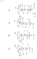
Fig. 4 is a diagram explanatory of the material piece extracting operation by the material piece extracting apparatus according to the first embodiment of the present invention, (A) showing the operation near the beginning of the extracting operation, (B) showing the operation in the course of the extracting operation and (C) showing the operation near the end of the extracting operation. -
Fig. 5 is a schematic diagram explanatory of the mechanism of the material piece extracting apparatus according to second embodiment of the present invention, (A) and (B) being front views and (C) being a side view. -
Fig. 6 is a diagram explanatory of the material piece extracting operation by the material piece extracting apparatus according to the second embodiment of the present invention, (A) showing the operation near the beginning of the extracting operation by a first tracing guide, (B) showing the operation near the end of the extracting operation by the first tracing guide, (C) showing the operation near the beginning of the extracting operation by a second tracing guide and (D) showing the operation near the end of the extracting operation by the second tracing guide. -
- 10
- Electric discharge electrode
- 10a
- Horizontal portion
- 10b
- Vertical portion
- 20
- Electrode holder
- 21
- Holding section
- 21a
- Mounting groove
- 21b
- Lid
- 30
- Arm
- 31
- Main body
- 32
- Sliding member
- 32a
- Sliding groove
- 33
- Insulator block
- 40
- Rotation drive means
- 41
- Rotation drive shaft
- 42
- Rotary stage
- 42a
- Slide guide
- 43
- Limit switch activator piece
- 50
- Base
- 51
- Vertical wall
- 52
- Opening
- 53
- Limit switch
- 61
- Urging spring
- 62
- Spring mounting plate
- 62a
- Protruding piece
- 63
- Spring set bolt
- 64
- Spring set bolt
- 65
- Tracing bolt
- 65a
- Roller
- 66
- Tracing guide
- 66a
- Guide surface
- 67
- Tracing bolt
- 67a
- Roller
- 67b
- Urging spring
- 67c
- Spacer
- 68
- First tracing guide
- 68a
- Guide surface
- 69
- Second tracing guide
- 69a
- Guide surface
- S
- Material piece
- W
- Width of electric discharge electrode
- X
- Axis of rotation
- Z
- Object to be extracted
- First, the material piece extracting apparatus according to the first embodiment will be described.
With reference made toFig. 1 andFig. 2 , the material piece extracting apparatus of the present invention comprises anelectric discharge electrode 10, anelectrode holder 20 whereon theelectric discharge electrode 10 can be detachably mounted, anarm 30 which holds theelectrode holder 20, and rotation drive means 40 which causes thearm 30 to rotate around an axis of rotation X. - The rotation drive means 40 is constituted from a motor such as servo motor. The rotation drive means 40 is fixed on a
base 50, and arotation drive shaft 41 of the rotation drive means 40 protrudes through anopening 52 formed in avertical wall 51 of thebase 50.
Therotation drive shaft 41 of the rotation drive means 40 has therotary stage 42 secured at the distal end thereof, therotary stage 42 being driven to rotate together with therotation drive shaft 41. The rotary table 42 is pivoted at the center thereof on therotation drive shaft 41 and rotates around it.
Therotation drive shaft 41 of the rotation drive means 40 also has a limitswitch activator piece 43 secured thereon at a mid position. The limitswitch activator piece 43 makes contact with a pair oflimit switches 53 mounted on the base 50 so as to turn on thelimit switch 53, thereby keeping therotation drive shaft 41 of the rotation drive means 40 from rotating further. The limitswitch activator piece 43 and thelimit switch 53 play the role of restricting the rotation of thearm 30 within a certain range. - The
arm 30 causes theelectric discharge electrode 10 to move along a circle about the axis of rotation of thearm 30.
Thearm 30 is constituted so as to be driven by therotation drive shaft 41 of the rotation drive means 40 to rotate around the axis of rotation X which corresponds to therotation drive shaft 41, while sliding in a direction perpendicular to the axis of rotation X.
Thearm 30 has the slidingmember 32 secured on one side of anmain body 31 which is formed in an elongated rectangular shape, and holds theelectrode holder 20 on the other side via aninsulation block 33.
The slidingmember 32 has a slide groove 32a. The rotary table 42 has, on the side thereof opposite to the slide groove 32a, the slide guide 42a which passes through the axis of rotation X that is the center of rotation of the rotary table 42 and extends in the direction perpendicular to the axis of rotation X. The slide guide 42a is fitted in the slide groove 32a of the slidingmember 32 so as to be capable of sliding relative to each other. Accordingly, thearm 30 can move sliding in direction perpendicular to the axis of rotation X.
The slidingmember 32 having the slide groove 32a and the slide guide 42a mounted on the rotary table 42 constitute the sliding means. - The
arm 30 is urged by the urgingspring 61 in the direction perpendicular to the axis of rotation X. Specifically, thearm 30 is urged by the urgingspring 61 in the sliding direction of the sliding means (32, 32a, 42a).
The urgingspring 61 is set between thespring set bolt 63 which is provided on the protruding piece 62a of the pair ofspring mounting plates 62 secured on both sides of the rotary table 42, and thespring set bolt 64 provided on both sides of themain body 31 of thearm 30. The protruding piece 62a of thespring mounting plate 62 extends from the rotary table 42 toward themain body 31 of thearm 30, and thespring set bolt 63 is disposed just above thespring set bolt 64 on the side face of themain body 31 of thearm 30.
Provided above themain body 31 of thearm 30 is thetracing bolt 65 having the roller 65a provided at the distal end thereof. In correspondence to thetracing bolt 65, the tracingguide 66 is provided on thevertical wall 51 of thebase 50. - The
tracing bolt 65 is disposed in parallel to the axis of rotation X of thearm 30, and the roller 65a disposed at the distal end thereof is in contact with the guide surface 66a formed on the bottom of the tracingguide 66. The roller 65a moves along the guide surface 66a as thearm 30 rotates, while being pressed by the urgingspring 61 against the guide surface 66a.
The tracingguide 66 is disposed on the circle drawn by the rotation of thearm 30. The guide surface 66a of the tracingguide 66 determines the trajectory along which theelectric discharge electrode 10 moves. As the roller 65a moves along the profile of the guide surface 66a, the sliding position of thearm 30 in the direction perpendicular to the axis of rotation X during rotation is determined, so that length of thearm 30 is adjusted. That is, length of thearm 30 from the axis of rotation X to the position where theelectric discharge electrode 10 is held is adjusted during rotation. As the length of thearm 30 is adjusted during rotation, the trajectory of theelectric discharge electrode 10 is controlled.
The urgingspring 61, thetracing bolt 65, the tracingguide 66 and the like (more specifically, the urgingspring 61, the spring setbolts tracing bolt 65 and the tracing guide 66) constitute the arm length adjusting means that adjusts the length of the arm from the axis of rotation X thereof. - The
electrode holder 20 is held on thearm 30 via theinsulation block 33. Theelectrode holder 20 has a holdingmember 21 which sandwiches theelectric discharge electrode 10 so as to detachably hold it. Theelectric discharge electrode 10 is fitted in a mounting groove 21a of the holdingmember 21 and is clamped by thelid 21b, so as to be held. As thearm 30 rotates, theelectrode holder 20 revolves around the axis of rotation X. - The
electric discharge electrode 10 is formed in C shape and is constituted so as to keep a constant width W in the direction perpendicular to the rotating direction (parallel to the axis of rotation X). Specifically, theelectric discharge electrode 10 has C shape consisting of ahorizontal portion 10a having the width W andvertical portions 10b extending from both ends of thehorizontal portion 10a. When the trajectory traced by the electric discharge electrode in accordance to the rotation of thearm 10 meets the object Z to be extracted, the material is removed from the portions of the object Z to be extracted which are close to and facing thehorizontal portion 10a and thevertical portions 10b. In the area of the object Z to be extracted which is enclosed by the configuration of the electric discharge electrode, on the other hand, the material is not removed. As a result, the material piece S having the width of W is taken out of the object Z to be extracted.
While theelectric discharge electrode 10 shown in the drawing has thehorizontal portion 10a and thevertical portions 10b crossing each other with an angle of 90 degrees, thehorizontal portion 10a and thevertical portions 10b may also be connected in U shape. The angle between thehorizontal portion 10a and thevertical portions 10b is not limited to 90 degrees, and may be larger than or smaller than 90 degrees. - With reference made to
Fig. 3 and Fig. 4 which simplify the material piece extracting apparatus, mechanism and operation of the material piece extracting apparatus according to the first embodiment will be described below.
When therotation drive shaft 41 of the rotation drive means 40 is driven to rotate, therotary stage 42 rotates accordingly, which in turn causes themain body 31 of thearm 30 to rotate. As thearm 30 rotates, theelectric discharge electrode 10 moves around the axis of rotation X via theelectrode holder 20. Thearm 30 can be caused to slide by the sliding means (32, 32a, 42a), while the roller 65a moves while being pressed against the guide surface 66a by the arm length adjusting means (61, 65, 66), so that length of the arm is adjusted in accordance to the surface irregularity of the guide surface 66a. As the length of thearm 30 is adjusted during rotation, trajectory of theelectric discharge electrode 10 is changed from the arc shape in the course of the rotation. - As shown in
Fig. 3(B) , the guide surface 66a of the tracingguide 66 has an arc-shaped surface as a whole with the mid portion being deeper than both sides. When the roller 65a passes the deep portion of the curved surface, length of the arm for rotating theelectric discharge electrode 10 is controlled to be shorter. As a result, theelectric discharge electrode 10 moves along such a trajectory that is arc-shaped at the start and the end which are connected by a boat-shaped portion which is proximate to straight line. After starting to gnaw into the object Z to be extracted along the arc-shape trajectory as shown inFig. 4(A) , theelectric discharge electrode 10 proceeds at a substantially constant depth as shown inFig. 4(B) , before emerging from within the object Z to be extracted along the arc-shape trajectory as shown inFig. 4(C) . As a result, the material piece S having the boat shape is taken out of the object Z to be extracted. - As the guide surface 66a of the tracing
guide 66 is formed in such a shape as theelectric discharge electrode 10 traces the boat-shaped trajectory as described above, the material piece S having the boat shape with width of W is taken out of the object Z to be extracted. Since the thickness of the material piece S having the boat shape can be kept constant, the material piece can be easily prepared for mechanical test and other tests. Also because gnawing into the object Z to be extracted can be carried out at a far smaller depth in comparison to a case of, for example, taking out an arc-shaped material piece, adverse effects on the strength and safety of the object Z to be extracted can be minimized even when it is a part of a facility currently in operation. - Various shapes of the guide surface 66a of the tracing
guide 66 can be employed in accordance to the shape of the material piece S to be extracted and the thickness and the shape of the object Z to be extracted. However, shapes of the guide surface 66a of the tracingguide 66 is preferably such that theelectric discharge electrode 10 gnaws into the object Z to be extracted with a larger angle at the start of gnawing and the end of gnawing while, in the mid portion, gnawing along a path parallel to the surface of the object Z to be extracted. - With reference made to
Fig. 5 andFig. 6 , the material piece extracting apparatus according to the second embodiment of the present invention will be described below. The apparatus of the second embodiment has a constitution substantially the same as the material piece extracting apparatus of the first embodiment, except for the constitution of thetracing bolt 67, thefirst tracing guide 68, and thesecond tracing guide 69.
The second embodiment employs theelectric discharge electrode 10 and theelectrode holder 20 which have dimensions a little different from those of the first embodiment. - In the second embodiment, the
tracing bolt 67 is provided to penetrate through thearm 30, and the roller 67a is provided at the distal end thereof. The urging spring 67b is provided on thetracing bolt 67 at a position behind thearm 30, so as to always urge thetracing bolt 67 backward (toward the rear end). A spacer 67c is detachably mounted on thetracing bolt 67 at a position in front of thearm 30, so that the spacer can be replaced with another one.
Fig. 5(A) shows such a constitution as the spacer 67c having small length is used so that the roller 67a is brought into contact with the guide surface 68a which is formed on the bottom of thefirst tracing guide 68.Fig. 5(B) shows such a constitution as the spacer 67c having large length is used so that the roller 67a is brought into contact with the guide surface 69a which is formed on the bottom of thesecond tracing guide 69. - The second embodiment is a case which uses the
first tracing guide 68 and thesecond tracing guide 69 in combination. Specifically, thesecond tracing guide 69 and thefirst tracing guide 68 are placed one on another and detachably mounted by screwing or the like on thevertical wall 51 of thebase 50.
The guide surfaces 68a, 68b formed on the bottom of thefirst tracing guide 68 and thesecond tracing guide 69 are disposed symmetrically on the right and left, respectively. The guide surfaces 68a, 69a are both formed so as to protrude downward in substantially V shape. In this embodiment, the sloped surface on the left side of the substantially V shape that constitutes the guide surface 68a of thefirst tracing guide 68 is actually used as the guide surface. In thesecond tracing guide 69, the sloped surface on the right side of the substantially V shape that constitutes the guide surface 69a of thesecond tracing guide 69 is used as the guide surface. - Now the apparatus of the second embodiment will be described with reference to
Fig. 6(A), Fig. 6(B), Fig. 6(C) and Fig. 6(D) which show the operation of the apparatus.
First, the shorter spacer 67c shown inFig. 5 (A) is used and set so that the roller 67a of thetracing bolt 67 makes contact with the guide surface 68a of thefirst tracing guide 68. Thearm 30 is set so as to rotate clockwise first. This causes theelectric discharge electrode 10 to start gnawing into the object Z to be extracted in an arc-shaped trajectory while turning clockwise (A). The electric discharge electrode turns clockwise until thearm 30 is disposed at right angles to the surface of the object Z to be extracted. Thearm 30 rotates while being guided by the substantially V-shaped guide surface 68a of thefirst tracing guide 68, and length of the arm is adjusted by sliding in the direction perpendicular to the axis of rotation X. Accordingly, in this embodiment, theelectric discharge electrode 10 gnaws into the object Z to be extracted in a straight path to the left downward from the surface of the object. When the electric discharge electrode has proceeded to the state shown inFig. 6(B) , the electric discharge machining is once stopped and theelectric discharge electrode 10 is removed from the object Z to be extracted by rotating thearm 30 in reverse direction or otherwise.
After theelectric discharge electrode 10 has been removed from the object Z to be extracted, the spacer 67c of thetracing bolt 67 is changed from the shorter one shown inFig. 5(A) to the longer one shown inFig. 5(B) .
Accordingly, the roller 67a of thetracing bolt 67 makes contact with the guide surface 69a of thesecond tracing guide 69.
Then thearm 30 is rotated counterclockwise. This causes theelectric discharge electrode 10 to start gnawing into the object to be extracted Z in an arc-shaped trajectory while turning counterclockwise (C). The electric discharge electrode turns counterclockwise until thearm 30 is disposed at right angles to the surface of the object Z to be extracted. Thearm 30 rotates while being guided by the substantially V-shaped guide surface 69a of thefirst tracing guide 69, and length of the arm is adjusted by sliding in the direction perpendicular to the axis of rotation X. Accordingly, in this embodiment, theelectric discharge electrode 10 gnaws into the object Z to be extracted in a straight path to the right downward from the surface of the object. When the electric discharge electrode has proceeded to the state shown inFig. 6(D) , rotation of thearm 30 is stopped and the electric discharge machining is stopped. In this process, a material piece S having V-shaped cross section is taken out of the object Z to be extracted.
Such a constitution is also within the scope of the present invention that, as in the second embodiment, besides combining the two tracing guides 68, 69, thearm 30 is driven to move reciprocally to take out the material piece S so that, by causing the arm 30 (the electric discharge electrode 10) to move reciprocally rather than one-way motion, thereby to take out the material piece S. - The material piece extracting apparatus of the present invention is capable of taking out a material piece from the surface of various structures including tubes, solid material, etc. made of various metallic materials. More particularly, the material piece extracting apparatus is capable of sampling a material piece or removing a defective portion from pipes and other constituent member of a facility which are currently functioning in the operating facility, while minimizing the damage caused on the facility and minimizing the deformation of the constituent member of the facility due to the extracting operation or the accompanying heat, thus offering great industrial utility.
Claims (7)
- A material piece extracting apparatus for extracting a material piece from the surface of an object to be extracted by generating an electric discharge between an electric discharge electrode and the object to be extracted so as to successively remove the material from the object to be extracted that is disposed to oppose the electric discharge electrode, the material piece extracting apparatus comprising rotation drive means, an arm driven to rotate around an axis of rotation by said rotation drive means, an electrode holder supported by said arm, and the electric discharge electrode detachably mounted on said electrode holder, while sliding means for sliding said arm in the direction perpendicular to said axis of rotation and arm length adjusting means for adjusting the length of the arm from the axis of rotation thereof, so as to adjust the trajectory of moving the electric discharge electrode as the arm is driven to rotate, and enable it to extract the material piece from the surface of the object to be extracted along a line which is followed by the trajectory of the electric discharge electrode gnawing into the object to be extracted.
- The material piece extracting apparatus according to claim 1, wherein the sliding means is disposed on the side of the rotation drive means, and comprises a slide guide mounted on a rotary stage which is driven to rotate, and a sliding member which is secured on the arm and is guided by said slide guide in the direction perpendicular to the axis of rotation.
- The material piece extracting apparatus according to claim 1 or 2, wherein the arm length adjusting means has an urging spring which urges the arm to slide in the direction perpendicular to the axis of rotation, and a tracing guide which is provided along the circle drawn by the rotation of the arm and makes contact with the arm and guides the arm so as to adjust the arm length during rotation.
- The material piece extracting apparatus according to claim 3, wherein a plurality of tracing guides are provided having different guide surfaces, from which a proper one is selected and detachably mounted.
- The material piece extracting apparatus according to claim 3 or 4, wherein a plurality of tracing guides are combined and mounted.
- The material piece extracting apparatus according to any one of claims 1 to 5, wherein the arm is driven to make one-way motion or reciprocal motion.
- The material piece extracting apparatus according to any one of claims 1 to 6, wherein depth of the trajectory through which the electric discharge electrode gnaws into the object to be extracted is controlled to be constant by the arm length adjusting means, thereby to control the thickness of the material piece to be extracted constant.
Applications Claiming Priority (1)
| Application Number | Priority Date | Filing Date | Title |
|---|---|---|---|
| PCT/JP2006/305015 WO2007105308A1 (en) | 2006-03-14 | 2006-03-14 | Material piece scooping device |
Publications (3)
| Publication Number | Publication Date |
|---|---|
| EP1995583A1 true EP1995583A1 (en) | 2008-11-26 |
| EP1995583A4 EP1995583A4 (en) | 2018-01-03 |
| EP1995583B1 EP1995583B1 (en) | 2019-06-19 |
Family
ID=38509159
Family Applications (1)
| Application Number | Title | Priority Date | Filing Date |
|---|---|---|---|
| EP06729049.4A Expired - Lifetime EP1995583B1 (en) | 2006-03-14 | 2006-03-14 | Material piece scooping device |
Country Status (6)
| Country | Link |
|---|---|
| US (1) | US7952045B2 (en) |
| EP (1) | EP1995583B1 (en) |
| JP (1) | JP3996182B1 (en) |
| KR (1) | KR100928498B1 (en) |
| CN (1) | CN101184982B (en) |
| WO (1) | WO2007105308A1 (en) |
Cited By (1)
| Publication number | Priority date | Publication date | Assignee | Title |
|---|---|---|---|---|
| CN113076936A (en) * | 2021-04-30 | 2021-07-06 | 华南理工大学 | Rope skipping counting method based on rope target extraction |
Families Citing this family (7)
| Publication number | Priority date | Publication date | Assignee | Title |
|---|---|---|---|---|
| US9527153B2 (en) | 2013-03-14 | 2016-12-27 | Lincoln Global, Inc. | Camera and wire feed solution for orbital welder system |
| US9770775B2 (en) * | 2013-11-11 | 2017-09-26 | Lincoln Global, Inc. | Orbital welding torch systems and methods with lead/lag angle stop |
| US9731385B2 (en) | 2013-11-12 | 2017-08-15 | Lincoln Global, Inc. | Orbital welder with wire height adjustment assembly |
| US9517524B2 (en) | 2013-11-12 | 2016-12-13 | Lincoln Global, Inc. | Welding wire spool support |
| JP6258025B2 (en) * | 2013-12-04 | 2018-01-10 | 株式会社神戸工業試験場 | Narrow part sampling head, narrow part sampling method and remaining life diagnosis method |
| CN109187070B (en) * | 2018-08-28 | 2021-05-07 | 国电锅炉压力容器检验有限公司 | Method for obtaining small punch rod sample of in-service high-temperature high-pressure pipeline |
| CN114603222A (en) * | 2022-03-14 | 2022-06-10 | 淮阴工学院 | Special machine for machining oil storage structure on inner wall of engine cylinder sleeve and working method of special machine |
Family Cites Families (18)
| Publication number | Priority date | Publication date | Assignee | Title |
|---|---|---|---|---|
| US3806691A (en) * | 1972-11-20 | 1974-04-23 | Cammann Mfg Co | Tool positioner |
| FR2599541B1 (en) * | 1986-06-03 | 1988-09-09 | Fragema Framatome & Cogema | METHOD AND INSTALLATION FOR TAKING THE TUBE SECTION FROM A NUCLEAR FUEL ASSEMBLY |
| JPS63146743U (en) | 1987-03-19 | 1988-09-28 | ||
| JPS63231238A (en) | 1987-03-20 | 1988-09-27 | Mitsubishi Heavy Ind Ltd | Parallel sample collector |
| US4948933A (en) * | 1989-02-27 | 1990-08-14 | Scan Systems, Inc. | Apparatus for cutting precision notches in work surfaces |
| FR2682803B1 (en) * | 1991-10-21 | 1993-12-03 | Framatome | PROCESS AND DEVICE FOR TAKING A TEST PIECE IN THE TANK OF A NUCLEAR REACTOR IN DEFINITIVE STOP. |
| JPH0633046U (en) | 1992-10-05 | 1994-04-28 | 三菱重工業株式会社 | Sampling device |
| JPH07159295A (en) | 1993-12-06 | 1995-06-23 | Hitachi Ltd | Method and device for collecting surface layer of metal material |
| US5569393A (en) * | 1994-07-08 | 1996-10-29 | Reinhart & Associates, Inc. | Method and apparatus for sample and defect removal from a bore |
| JPH08108319A (en) * | 1994-10-07 | 1996-04-30 | Mitsubishi Heavy Ind Ltd | Sampling device for small tube |
| JPH09155646A (en) | 1995-12-06 | 1997-06-17 | Mitsubishi Heavy Ind Ltd | Sample sampling method |
| US5818006A (en) * | 1995-12-07 | 1998-10-06 | Ford Global Technologies, Inc. | Surface preparation electrical discharge apparatus and method |
| JP3152607B2 (en) | 1996-02-14 | 2001-04-03 | 株式会社日立製作所 | Micro sample collection apparatus and method |
| JP3468990B2 (en) | 1996-06-17 | 2003-11-25 | 三菱重工業株式会社 | Heat exchanger tube sampling equipment |
| JPH1076427A (en) | 1996-09-03 | 1998-03-24 | Hitachi Ltd | Reactor internal structure sampling equipment |
| US5861608A (en) * | 1996-11-07 | 1999-01-19 | Ico, Inc. | EDM cutting machine for precision notching tubulars |
| US5897793A (en) * | 1997-02-24 | 1999-04-27 | General Electric Company | Methods and apparatus for machining a pipe in a nuclear reactor |
| JP2001079658A (en) | 1999-09-17 | 2001-03-27 | Mitsubishi Heavy Ind Ltd | Method and apparatus for sampling the nozzle weld |
-
2006
- 2006-03-14 JP JP2006554382A patent/JP3996182B1/en not_active Expired - Lifetime
- 2006-03-14 EP EP06729049.4A patent/EP1995583B1/en not_active Expired - Lifetime
- 2006-03-14 WO PCT/JP2006/305015 patent/WO2007105308A1/en not_active Ceased
- 2006-03-14 KR KR1020077025901A patent/KR100928498B1/en not_active Expired - Lifetime
- 2006-03-14 CN CN2006800188387A patent/CN101184982B/en not_active Expired - Lifetime
- 2006-03-14 US US11/922,584 patent/US7952045B2/en active Active
Non-Patent Citations (1)
| Title |
|---|
| See references of WO2007105308A1 * |
Cited By (1)
| Publication number | Priority date | Publication date | Assignee | Title |
|---|---|---|---|---|
| CN113076936A (en) * | 2021-04-30 | 2021-07-06 | 华南理工大学 | Rope skipping counting method based on rope target extraction |
Also Published As
| Publication number | Publication date |
|---|---|
| JP3996182B1 (en) | 2007-10-24 |
| KR100928498B1 (en) | 2009-12-01 |
| KR20080009709A (en) | 2008-01-29 |
| JPWO2007105308A1 (en) | 2009-07-30 |
| CN101184982B (en) | 2012-02-22 |
| EP1995583A4 (en) | 2018-01-03 |
| CN101184982A (en) | 2008-05-21 |
| US20100012627A1 (en) | 2010-01-21 |
| US7952045B2 (en) | 2011-05-31 |
| EP1995583B1 (en) | 2019-06-19 |
| WO2007105308A1 (en) | 2007-09-20 |
Similar Documents
| Publication | Publication Date | Title |
|---|---|---|
| JP4632962B2 (en) | Coaxiality / perpendicularity measuring apparatus and method | |
| EP2503315B1 (en) | Microtome with surface orientation sensor to sense orientation of surface of sample | |
| EP1995583B1 (en) | Material piece scooping device | |
| KR101847922B1 (en) | Ultrasound devices of turbine rotor finger dovetail | |
| US5146823A (en) | Method and apparatus for precision cutting of corrugated paperboard specimens | |
| CN114942200A (en) | Method for analyzing sharpness of straight-edged tool for ultrasonic machining of honeycomb material | |
| US3906784A (en) | Bend test machine for weld coupon samples | |
| CN108645366B (en) | An experimental device for measuring the non-parallelism of both ends of rock | |
| JP2003247923A (en) | Material testing machine | |
| CN120468307A (en) | A nondestructive detection device for cracks in fusion welding of natural gas pipelines | |
| KR101107257B1 (en) | Portable measuring device for evaluating the hardness and microstructure of high temperature and high pressure piping | |
| JP2006162344A (en) | Tool shape measuring apparatus and method | |
| JP2006102900A (en) | Specimen sampling device | |
| JP2004279181A (en) | Ultrasonic flaw detector and ultrasonic flaw detection method | |
| WO2023200995A1 (en) | System and method to measure material ductility and toughness using cutting blades | |
| KR20030012566A (en) | A Fatigue Tester for Rubber Material and Rubber Component | |
| JP6128635B2 (en) | Machined hole position measuring device | |
| US3138016A (en) | Fatigue cracking test apparatus | |
| KR100950360B1 (en) | Shape measuring device of steel plate | |
| KR100919879B1 (en) | support device of ultrasonic testing apparatus | |
| CN219065364U (en) | TOFD (time of flight diffraction) detection equipment with high detection precision | |
| CN117890473B (en) | Nondestructive testing device for turbine blade | |
| US20050050961A1 (en) | Method and apparatus for determining hydrogen embrittlement | |
| CN214374590U (en) | Positioning mechanism and flaw detection scanning device | |
| CN120572397A (en) | An online force, heat, and deformation measurement test device for cutting thin-walled cylindrical parts and its use method |
Legal Events
| Date | Code | Title | Description |
|---|---|---|---|
| PUAI | Public reference made under article 153(3) epc to a published international application that has entered the european phase |
Free format text: ORIGINAL CODE: 0009012 |
|
| 17P | Request for examination filed |
Effective date: 20071121 |
|
| AK | Designated contracting states |
Kind code of ref document: A1 Designated state(s): CZ DE FR GB IT |
|
| DAX | Request for extension of the european patent (deleted) | ||
| RBV | Designated contracting states (corrected) |
Designated state(s): CZ DE FR GB IT |
|
| RAP1 | Party data changed (applicant data changed or rights of an application transferred) |
Owner name: KYUSHU ELECTRIC POWER CO., INC. Owner name: KOBE MATERIAL TESTING LABORATORY CO., LTD. |
|
| RA4 | Supplementary search report drawn up and despatched (corrected) |
Effective date: 20171201 |
|
| RIC1 | Information provided on ipc code assigned before grant |
Ipc: B23H 1/00 20060101ALI20171127BHEP Ipc: G01N 1/04 20060101AFI20171127BHEP |
|
| STAA | Information on the status of an ep patent application or granted ep patent |
Free format text: STATUS: EXAMINATION IS IN PROGRESS |
|
| 17Q | First examination report despatched |
Effective date: 20180808 |
|
| GRAP | Despatch of communication of intention to grant a patent |
Free format text: ORIGINAL CODE: EPIDOSNIGR1 |
|
| STAA | Information on the status of an ep patent application or granted ep patent |
Free format text: STATUS: GRANT OF PATENT IS INTENDED |
|
| INTG | Intention to grant announced |
Effective date: 20190108 |
|
| GRAS | Grant fee paid |
Free format text: ORIGINAL CODE: EPIDOSNIGR3 |
|
| GRAA | (expected) grant |
Free format text: ORIGINAL CODE: 0009210 |
|
| STAA | Information on the status of an ep patent application or granted ep patent |
Free format text: STATUS: THE PATENT HAS BEEN GRANTED |
|
| AK | Designated contracting states |
Kind code of ref document: B1 Designated state(s): CZ DE FR GB IT |
|
| REG | Reference to a national code |
Ref country code: GB Ref legal event code: FG4D |
|
| REG | Reference to a national code |
Ref country code: DE Ref legal event code: R096 Ref document number: 602006058163 Country of ref document: DE |
|
| REG | Reference to a national code |
Ref country code: DE Ref legal event code: R097 Ref document number: 602006058163 Country of ref document: DE |
|
| PLBE | No opposition filed within time limit |
Free format text: ORIGINAL CODE: 0009261 |
|
| STAA | Information on the status of an ep patent application or granted ep patent |
Free format text: STATUS: NO OPPOSITION FILED WITHIN TIME LIMIT |
|
| 26N | No opposition filed |
Effective date: 20200603 |
|
| PGFP | Annual fee paid to national office [announced via postgrant information from national office to epo] |
Ref country code: DE Payment date: 20250331 Year of fee payment: 20 |
|
| PGFP | Annual fee paid to national office [announced via postgrant information from national office to epo] |
Ref country code: FR Payment date: 20250325 Year of fee payment: 20 Ref country code: CZ Payment date: 20250306 Year of fee payment: 20 |
|
| PGFP | Annual fee paid to national office [announced via postgrant information from national office to epo] |
Ref country code: IT Payment date: 20250325 Year of fee payment: 20 Ref country code: GB Payment date: 20250319 Year of fee payment: 20 |
|
| REG | Reference to a national code |
Ref country code: DE Ref legal event code: R071 Ref document number: 602006058163 Country of ref document: DE |
|
| REG | Reference to a national code |
Ref country code: GB Ref legal event code: PE20 Expiry date: 20260313 |
|
| PG25 | Lapsed in a contracting state [announced via postgrant information from national office to epo] |
Ref country code: CZ Free format text: LAPSE BECAUSE OF EXPIRATION OF PROTECTION Effective date: 20260314 |