EP1995444A2 - Kompakter, Hochleistungs-Drallverbrennungsmotor für Raketen - Google Patents
Kompakter, Hochleistungs-Drallverbrennungsmotor für Raketen Download PDFInfo
- Publication number
- EP1995444A2 EP1995444A2 EP08250859A EP08250859A EP1995444A2 EP 1995444 A2 EP1995444 A2 EP 1995444A2 EP 08250859 A EP08250859 A EP 08250859A EP 08250859 A EP08250859 A EP 08250859A EP 1995444 A2 EP1995444 A2 EP 1995444A2
- Authority
- EP
- European Patent Office
- Prior art keywords
- combustor
- nozzle
- rocket engine
- exterior
- swirl
- Prior art date
- Legal status (The legal status is an assumption and is not a legal conclusion. Google has not performed a legal analysis and makes no representation as to the accuracy of the status listed.)
- Withdrawn
Links
- 238000002485 combustion reaction Methods 0.000 title claims abstract description 133
- 239000000446 fuel Substances 0.000 claims abstract description 75
- 239000007800 oxidant agent Substances 0.000 claims abstract description 38
- 238000000034 method Methods 0.000 claims abstract description 4
- 239000003380 propellant Substances 0.000 claims description 83
- 239000007788 liquid Substances 0.000 claims description 41
- 238000001816 cooling Methods 0.000 claims description 11
- 238000012546 transfer Methods 0.000 claims description 10
- 230000001172 regenerating effect Effects 0.000 claims description 9
- 239000006227 byproduct Substances 0.000 claims description 4
- 239000007921 spray Substances 0.000 claims description 2
- 238000002156 mixing Methods 0.000 abstract description 15
- 230000008569 process Effects 0.000 abstract description 2
- 239000007789 gas Substances 0.000 description 43
- 238000005516 engineering process Methods 0.000 description 23
- VNWKTOKETHGBQD-UHFFFAOYSA-N methane Chemical compound C VNWKTOKETHGBQD-UHFFFAOYSA-N 0.000 description 16
- MYMOFIZGZYHOMD-UHFFFAOYSA-N Dioxygen Chemical compound O=O MYMOFIZGZYHOMD-UHFFFAOYSA-N 0.000 description 15
- 238000013461 design Methods 0.000 description 15
- 238000002347 injection Methods 0.000 description 11
- 239000007924 injection Substances 0.000 description 11
- 239000000203 mixture Substances 0.000 description 9
- 230000008901 benefit Effects 0.000 description 8
- 239000001257 hydrogen Substances 0.000 description 7
- 229910052739 hydrogen Inorganic materials 0.000 description 7
- UFHFLCQGNIYNRP-UHFFFAOYSA-N Hydrogen Chemical compound [H][H] UFHFLCQGNIYNRP-UHFFFAOYSA-N 0.000 description 6
- 239000000470 constituent Substances 0.000 description 6
- 230000006641 stabilisation Effects 0.000 description 6
- 238000011105 stabilization Methods 0.000 description 6
- PEDCQBHIVMGVHV-UHFFFAOYSA-N Glycerine Chemical compound OCC(O)CO PEDCQBHIVMGVHV-UHFFFAOYSA-N 0.000 description 5
- 238000013459 approach Methods 0.000 description 5
- 238000003860 storage Methods 0.000 description 4
- 238000000889 atomisation Methods 0.000 description 3
- 230000003190 augmentative effect Effects 0.000 description 3
- 239000012530 fluid Substances 0.000 description 3
- 230000006872 improvement Effects 0.000 description 3
- 238000003780 insertion Methods 0.000 description 3
- 230000037431 insertion Effects 0.000 description 3
- 239000000047 product Substances 0.000 description 3
- 238000004513 sizing Methods 0.000 description 3
- 239000007787 solid Substances 0.000 description 3
- 238000012360 testing method Methods 0.000 description 3
- 230000008016 vaporization Effects 0.000 description 3
- 102100021923 Prolow-density lipoprotein receptor-related protein 1 Human genes 0.000 description 2
- 230000000712 assembly Effects 0.000 description 2
- 238000000429 assembly Methods 0.000 description 2
- QVGXLLKOCUKJST-UHFFFAOYSA-N atomic oxygen Chemical compound [O] QVGXLLKOCUKJST-UHFFFAOYSA-N 0.000 description 2
- 239000002826 coolant Substances 0.000 description 2
- 230000007717 exclusion Effects 0.000 description 2
- 239000007792 gaseous phase Substances 0.000 description 2
- 239000003350 kerosene Substances 0.000 description 2
- 239000001301 oxygen Substances 0.000 description 2
- 229910052760 oxygen Inorganic materials 0.000 description 2
- 239000012071 phase Substances 0.000 description 2
- 230000001141 propulsive effect Effects 0.000 description 2
- 230000003134 recirculating effect Effects 0.000 description 2
- 230000009467 reduction Effects 0.000 description 2
- 230000002459 sustained effect Effects 0.000 description 2
- 238000011144 upstream manufacturing Methods 0.000 description 2
- 238000009834 vaporization Methods 0.000 description 2
- 239000004215 Carbon black (E152) Substances 0.000 description 1
- 101710202113 Prolow-density lipoprotein receptor-related protein 1 Proteins 0.000 description 1
- 230000002411 adverse Effects 0.000 description 1
- 230000003466 anti-cipated effect Effects 0.000 description 1
- 230000003416 augmentation Effects 0.000 description 1
- 238000009835 boiling Methods 0.000 description 1
- 230000008859 change Effects 0.000 description 1
- 238000006243 chemical reaction Methods 0.000 description 1
- 239000000567 combustion gas Substances 0.000 description 1
- 230000008602 contraction Effects 0.000 description 1
- 238000011161 development Methods 0.000 description 1
- 238000009826 distribution Methods 0.000 description 1
- 230000009977 dual effect Effects 0.000 description 1
- 230000008030 elimination Effects 0.000 description 1
- 238000003379 elimination reaction Methods 0.000 description 1
- 238000001704 evaporation Methods 0.000 description 1
- 230000008020 evaporation Effects 0.000 description 1
- 229930195733 hydrocarbon Natural products 0.000 description 1
- 150000002430 hydrocarbons Chemical class 0.000 description 1
- 150000002431 hydrogen Chemical class 0.000 description 1
- 239000007791 liquid phase Substances 0.000 description 1
- 238000004519 manufacturing process Methods 0.000 description 1
- 230000007246 mechanism Effects 0.000 description 1
- 231100000252 nontoxic Toxicity 0.000 description 1
- 230000003000 nontoxic effect Effects 0.000 description 1
- 238000005457 optimization Methods 0.000 description 1
- 230000001590 oxidative effect Effects 0.000 description 1
- 238000004806 packaging method and process Methods 0.000 description 1
- 230000035515 penetration Effects 0.000 description 1
- 238000011084 recovery Methods 0.000 description 1
- 238000000926 separation method Methods 0.000 description 1
- 230000007480 spreading Effects 0.000 description 1
- 238000003892 spreading Methods 0.000 description 1
- 230000035899 viability Effects 0.000 description 1
Images


Classifications
-
- F—MECHANICAL ENGINEERING; LIGHTING; HEATING; WEAPONS; BLASTING
- F02—COMBUSTION ENGINES; HOT-GAS OR COMBUSTION-PRODUCT ENGINE PLANTS
- F02K—JET-PROPULSION PLANTS
- F02K9/00—Rocket-engine plants, i.e. plants carrying both fuel and oxidant therefor; Control thereof
- F02K9/42—Rocket-engine plants, i.e. plants carrying both fuel and oxidant therefor; Control thereof using liquid or gaseous propellants
- F02K9/60—Constructional parts; Details not otherwise provided for
- F02K9/62—Combustion or thrust chambers
- F02K9/64—Combustion or thrust chambers having cooling arrangements
-
- F—MECHANICAL ENGINEERING; LIGHTING; HEATING; WEAPONS; BLASTING
- F02—COMBUSTION ENGINES; HOT-GAS OR COMBUSTION-PRODUCT ENGINE PLANTS
- F02K—JET-PROPULSION PLANTS
- F02K9/00—Rocket-engine plants, i.e. plants carrying both fuel and oxidant therefor; Control thereof
- F02K9/42—Rocket-engine plants, i.e. plants carrying both fuel and oxidant therefor; Control thereof using liquid or gaseous propellants
- F02K9/44—Feeding propellants
- F02K9/46—Feeding propellants using pumps
- F02K9/48—Feeding propellants using pumps driven by a gas turbine fed by propellant combustion gases or fed by vaporized propellants or other gases
-
- F—MECHANICAL ENGINEERING; LIGHTING; HEATING; WEAPONS; BLASTING
- F02—COMBUSTION ENGINES; HOT-GAS OR COMBUSTION-PRODUCT ENGINE PLANTS
- F02K—JET-PROPULSION PLANTS
- F02K9/00—Rocket-engine plants, i.e. plants carrying both fuel and oxidant therefor; Control thereof
- F02K9/42—Rocket-engine plants, i.e. plants carrying both fuel and oxidant therefor; Control thereof using liquid or gaseous propellants
- F02K9/44—Feeding propellants
- F02K9/52—Injectors
Definitions
- the present invention is applicable to a class of rocket engines that provide vacuum thrust covering a range of approximately 500 lb f - 20,000 lb f and 25,000 lb f - 100,000 lb f , featuring advanced swirl combustion, and can be used to meet the throttling propulsion needs for traveling to the Moon, Mars and beyond.
- the liquid propulsion engine upper stage and spacecraft rocket engine market continues to receive emphasis, especially for storable non-toxic and cryogenic propellant systems, high expansion nozzles and orbit maneuvering systems.
- ELV upper stage Expendable Launch Vehicles
- the generated vacuum thrust varies from approximately 25,000 lb f - 60,000 lb f for. Atlas 5 and the Delta-IV (small, medium and heavy) launch vehicles.
- Future potential growth is anticipated in this mid-thrust range liquid ELV rocket propulsion market, with expected vacuum thrust needed in the range of approximately 25,000 lb f to about 100,000 lb f .
- the above architecture study specified a high specific impulse (Isp) propulsion system for the SM and lunar ascent that would provide high reliability without significant propellant boil-off
- Isp specific impulse
- a human rated 5,000 lb f - 20,000 lb f pressure/pump fed Liquid Oxygen (LOX) /Methane (CH4) in-space propulsion engine has been specified in the study for both the SM and LSAM ascent stage and for the upgraded pump-fed version.
- a throttleable 5,000 lb f - 20,000 lb f pressure/pump-fed (gas generator or expander turbo-pump feed system), deep-throttling engine has been identified to support the return to the Moon.
- the propellants chosen consist of LOX/liquid hydrogen (LH2).
- LH2 pump-fed propulsion engine was selected for the lunar descent stage due to its higher Isp performance, lower cost and risk level relative to a pressure-fed system, which will allow the LSAM to perform a circular burn, yet maximize the LSAM cargo delivery capability.
- these engines must have a restart capability for lunar descent and the ability to throttle down to 10 percent of the total thrust.
- common pressure-fed LOX/CH4 engines were chosen for the CEV Service Module and lunar ascent stage propulsion systems in order to attain high reliability performance engines with similar propellants.
- Compact Advanced Swirl-combustion Propulsion (CASP) technology that can be used in a broad range of rocket-based and air-breathing propulsion applications has recently been successfully developed and test demonstrated. It is simple and has no moving parts.
- the swirl generator is the central key feature of the CASP technology, which enables robust mixing of propellants, flame stabilization and flame propagation that produces near complete combustion over a wide range of compact combustor lengths and diameters.
- CASP technology was originally developed and tested as an auxiliary ramjet thrust propulsion system to provide additional lift thrust augmentation for the Boeing Joint Strike Fighter (JSF) Short Take-off Vertical Landing aircraft (See “COMPACT, LIGHTWEIGHT HIGH-PERFORMANCE LIFT THRUSTER INCORPORATING SWIRL-AUGMENTED OXIDIZER/FUEL INJECTION, MIXING AND COMBUSTION," U.S. Patent No.
- Propulsive efficiency of the CASP engine was approximately constant at 93% over mid to high equivalence ratio ranges (growth capability to about 96%) and consistently higher than historical ramjet flightweight engines, yet the CASP combustor length was 36% shorter.
- Test-to-test performance repeatability of the CASP was excellent, with excursions below ⁇ 2.2%.
- the tested combustor / convergent nozzle length to combustor diameter ratio, L/D was only 1.6, with further potential for reducing the L/D down to 1.0 or less.
- the swirl generator design is quite flexible and has been implemented in many other propulsion applications with similar benefits. For example, it has been employed to introduce novel: (1) Compact, Lightweight Ramjet Engines Incorporating Swirl Augmented Combustion With Improved Performance, (see U.S. Patents 6,968,695 and 7,137,255 by S. Schmotolocha et al .); (2) Compact Swirl Augmented Afterburners for Gas Turbine Engines (see U.S. Patents 6,895,756 and 7,137,255 by Schmotolocha et al .); and (3) Combined Cycle Engines Incorporating Swirl Augmented Combustion for Reduced Volume and Weight and Improved Performance (see U.S. Patent 6,907,724 by R. Edelman et al .).
- the resulting key benefits to NASA, DoD and the commercial launch market for small-to-medium size rocket engines would include: (1) a significant reduction in combustor length, weight and complexity; (2) a greater nozzle expansion ratios to provide higher vacuum Isp can be introduced into fixed rocket engine lengths due to shorter combustor length; (3) reduced combustor cooling requirements due to a shorter combustor length; (4) improved engine performance (high Isp) and operability; (5) engine throttling ability; and (6) enhanced safety and lower system part count, which results in reduced complexity and manufacturing cost.
- the CASP propulsion system is highly reliable and the attendant propellants injection approach is extremely flexible. The latter allows the engine design to be tuned to achieve near maximum theoretical performance (thrust, Isp, propulsive and combustion efficiencies).
- Typical feed systems used to fuel rocket propulsion combustors such as simple gas pressure or turbo-pump feed systems, have limited throttling ratios (the rocket engine's maximum thrust capability compared to the minimum thrust capability).
- Gas pressure feed systems are capable of achieving throttling ratios of approximately 10:1, such as the pressure-fed Apollo descent engine.
- Turbo-pump feed systems currently achieve throttling ratios of 5:1.
- a rocket engine that utilizes a gas pressure feed system operating at low tank pressure and low combustion chamber pressure (P c ) results in an undesirably large sized rocket engine that has poor propulsion performance.
- the present invention is directed toward a rocket engine that provides vacuum thrust in approximately the 500 lb f - 20,000 lb f and 25,00 lb f - 100,000 lb f range.
- Components of the rocket engine include a feed system, combustor assembly, swirl generator and a nozzle.
- the feed system delivers an oxidizer and a fuel to the combustor assembly in the appropriate phase (liquid or gas) suitable for use with the swirl generator, while the combustor assembly carries out the combustion process of fuel and oxidizer, and the nozzle expands the flow and produces thrust.
- the swirl generator positioned within the combustor assembly, causes a highly-turbulent three-dimensional swirling central recirculation zone to form in the combustor that is used for flame stabilization and robust flame propagation.
- Gaseous oxidant or fuel is introduced axially and swirled.
- a second liquid combustion constituent is then injected into this swirling turbulent flowfield followed by vigorous atomization, vaporization, mixing and combustion.
- These aerothermodynamic processes are extremely efficient and consequently produce near ideal thrust levels.
- the benefits of using the CASP swirl combustion technology are the ability to significantly reduce combustor length, weight, complexity and cost, yet provide high propulsion efficiencies and wide rocket engine throttling operability.
- the swirl generator can be integrated into a high thrust, dual-throat, expansion/deflection rocket engine to provide deep throttleability with high Isp that meets propulsion needs for traveling to the Moon, Mars and beyond.
- FIG. 1 shows a schematic of a compact, high performance swirl combustion rocket engine of the present invention.
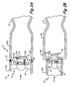
- FIG. 2A shows a rocket engine combustor featuring a propellant swirl generator having a straight combustor for use in the rocket engine of FIG. 1 .
- FIG. 2B shows a rocket engine combustor featuring a propellant swirl generator having a dump-step combustor for use in the rocket engine of FIG. 1 .
- FIG. 3 shows the resulting combustion flowfield for a rocket engine with a swirl generator and a dump-step combustor such as that of FIG. 2B .
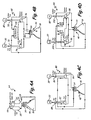
- FIG.4A shows a schematic of a gas pressure feed system for use with the swirl combustion rocket engine of FIG. 1 .
- FIG. 4B shows a schematic of an open cycle gas generator turbopump feed system for use with the swirl combustion rocket engine of FIG. 1 .
- FIG. 4C shows a schematic of a closed cycle expander turbopump feed system for use with the swirl combustion rocket engine of FIG. 1 .
- FIG. 4D shows a schematic of a closed cycle staged combustion turbopump feed system for use with the swirl combustion rocket engine of FIG. 1 .
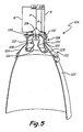
- FIG. 5 shows a high thrust, dual-throat, expansion/deflection rocket engine with a swirl generator integrated into an interior thrust chamber to provide deep engine throttleability.
- FIG. 1 shows a schematic of compact, high performance, swirl combustion rocket engine 10 of the present invention.
- Rocket engine 10 is comprised of a swirl-enhanced combustor 12, swirl generator 14, convergent/divergent nozzle 16, first storage tank 18 for propellant A, second storage tank 20 for propellant B, and feed system 21.
- Rocket engine 10 carries a supply of propellants A and B, typically a fuel and an oxidizer, within tanks 18 and 20 for use in a combustion process within combustor 12 necessary for generating thrust for propelling rocket engine 10.
- Liquid propellants A and B are supplied to swirl-enhanced combustor 12 through gas pressure feed system 21, whereby a variety of fuel injectors, such as positioned on combustor 12 inlet wall or within swirl generator 14, distribute propellants A and B for use in the combustion processes.
- feed system 21 comprises a pressurized feed system, and in other embodiments feed system 21 comprises a turbo-pump feed system. Feed system 21 ensures that propellants A and B are delivered to combustor 12 in a phase suitable for use with swirl generator 14 and also performs regenerative heat transfer cooling of combustor 12 and nozzle 16.
- Swirl generator 14 imparts a highly turbulent three-dimensional aerodynamic flow structure into the flowstream of first propellant A as it passes through to combustor 12.
- second propellant B is injected, mixed and burned.
- the radial and tangential components of the burning swirl flow rapidly decay throughout combustor 12 and nozzle 18 due to the design of swirl generator 14, thereby reducing the required length and diameter of combustor 12.
- Byproducts of the combustion process are passed through nozzle 16, which is located at the downstream end of swirl combustor 12, to produce additional thrust.
- rocket engine 12 incorporates feed system 21 to optimally deliver propellants A and B to combustor 12, and swirl generator 14 to optimally mix propellants A and B within combustor 12 to achieve a compact, high performance rocket engine with medium to large thrusting capabilities.
- FIG. 2A shows a first embodiment of rocket engine 10 of the present invention, comprising combustor 12, swirl generator 14, convergent/divergent nozzle 16, delivery duct 22A and combustion chamber 24A, for use with liquid rocket propellants A and B.
- Inlet delivery duct 22A directs propellant A to the swirl generator 14, which is comprised of swirl vanes 26, centerbody 28, bluffbody 30, and fuel injectors 32, 34, 36, 38, 40, 42 and 44 for introducing propellant B into combustion chamber enclosed by wall 24A.
- FIG. 2B shows swirl-enhanced combustor 46, which includes similar components as combustor 12, such as inlet delivery duct 22B and combustion chamber 24B, in addition to ramp 48 and dump-step 50.
- Swirl generator 14 is positioned at the entrance of combustion chamber 24A or 24B for use with swirl combustor 12 and swirl-dump combustor 46, respectively.
- inlet delivery duct 22A and combustion chamber 24A align coaxially to form a generally straight propellant flow path, with swirl generator 14 being positioned such that bluffbody 30 is positioned downstream of injectors 32 and 34.
- inlet delivery duct 22B has a smaller diameter than combustion chamber 24B, which is further reduced by ramp 48.
- Inlet delivery duct 22B and combustion chamber 24B are connected by dump step 50. Together ramp 48 and dump step 50 provide an expansion in the propellant flow path.
- Dump step 50 can be configured as a ninety degree step as illustrated in FIG. 2B , or somewhat less to form a quarl, or be a rounded or elliptical dome, or any other geometric shape that aerodynamically simulates an efficient dump step.
- swirl generator 14 is positioned such that bluffbody 30 is positioned downstream of ramp 48 and dump step 50. The position of swirl generator 14, however, may be adjusted in other embodiments.
- swirl generator 14 improves mixing of the two propellants A and B and then considerably accelerates their combustion process to completion in much shorter combustor length to produce neatly ideal thrust performance.
- An axial flow stream of a first propellant A enters the delivery duct 22A or 22B and is directed through swirl generator 14.
- a plurality of stationary swirl vanes 26 are attached to the delivery duct 22A or 22B at the tip and to the centerbody 28 at the root such that they sit in a predetermined angle to the incoming flow of propellant A.
- Centerbody 28 extends downstream of the swirl vanes 26, then terminates with bluffbody 30. The downstream end of the centerbody 28 is directly integrated with bluffbody 30.
- FIGS. 2A and 2B depict both a solid-flared conical bluffbody 30A and a channeled bluffbody 30B.
- bluffbody concepts such as a hollow cone bluffbody that could house fuel injector 44 or an igniter are possible.
- first propellant A enters swirl generator 14, and swirl vanes 26, which impart radial and tangential velocities, causing a change in the flow direction and produces a swirling, highly turbulent, three-dimensional flowfield having a large central recirculation zone (CRZ) downstream of bluffbody 30, and a toroidal outer recirculation zone (ORZ) downstream of dump-step 50 ( FIG. 2B ).
- the flow stream continues downstream from swirler 14, over centerbody 28 and bluffbody 30.
- Second propellant B is injected into the turbulent swirling flow of propellant A downstream of swirl vanes 26, whereupon the two constituents mix while entering combustion chamber 24A or 24B.
- Bluffbody 30 anchors the CRZ vortex and the dump-step anchors the ORZ vortex such that combustion is stabilized by either bluffbody design 30A or 30B and/or dump-step 50.
- Swirler vanes 26 enable swirl generator 14 to produce robust mixing, and together with bluffbody 30 and dump-step 50 improve the combustion process, thereby facilitating the use of high-performance swirl-dump combustors 12 and 46 in rocket engine 10.
- FIG. 3 shows a cross-section of a swirl-dump combustor 46 of FIG. 2B and its resulting aerodynamic flowfield 52 for use in a rocket engine 10 of the present invention.
- Swirl-dump combustor 46 is comprised of a swirl generator 14, nozzle 16, delivery duct 22B, combustion chamber 24B, swirl vanes 26, wall injectors 32 and 34, centerbody injectors 36 and 38, bluffbody injectors 42 and 44, ramp 48 and dump-step 50 to achieve robust mixing and high-performance combustion in a short combustor length to diameter ratio, L/D, of 1.6 and less.
- Propellant A is introduced into inlet delivery duct 22B from tank 18 by feed system 21 ( FIG. 1 ).
- Swirl-dump combustor 46 contains a plurality of injectors, including bluffbody injectors 42 and 44, centerbody injectors 36 and 38, and wall injectors 32 and 34 for injecting second propellant B from tank 20 and feed system 21 ( FIG. 1 ) into inlet delivery duct 22B.
- Propellants A and B comprise combustion constituents appropriate for use with swirl generator 14, such as cryogenic liquid oxygen (LOX), gaseous hydrogen (GH2), gaseous methane (GCH4), gaseous oxygen (GOX), liquid kerosene (LRP-1), or some other hydrocarbon fuel.
- LOX cryogenic liquid oxygen
- GH2 gaseous hydrogen
- GCH4 gaseous methane
- GOX gaseous oxygen
- LRP-1 liquid kerosene
- other embodiments of swirl-dump combustor 46 or combustor 12 could utilize other types of propellant oxidizer/fuel combinations.
- Injectors 32 - 34 can be positioned in various combinations and positions along the circumference of inlet delivery duct 22B, such as wall injectors 42 and 44, which in this example are flush to the inner wall and/or they can be protruding into the flow stream. Moreover, injectors can also be located circumferentially along centerbody 28, as shown with injectors 36 and 38, or along bluffbody 30, such as bluffbody injectors 42 and 44. Injectors 32 through 44 may comprise orifice type, pressurized simplex/duplex type, fan spray atomizer injectors, variable area injectors or other types as those who are skilled in the art are familiar with. All injectors of the present invention are located downstream of the swirl vanes 26 to reduce the potential for flame flashback and to mitigate damage to these blades.
- CRZ 54 While mixing, propellants A and B pass over ramp 48 and by dump-step 50, bluffbody 30 and enter combustion chamber 24B, so that CRZ 54 and ORZ 56 are established within combustion chamber 24B.
- Swirl generator 14 creates a highly turbulent, three-dimensional flowfield with CRZ 54 as the main flame stabilization mechanism.
- CRZ 54 is a large-scale vortex which is anchored by the downstream end of the bluffbody 30A or 30B, and is the primary recirculation zone. The size and strength of the vortex of CRZ 54 determines and controls flame parameters including stability, combustion intensity, and residence time distributions.
- CRZ 54 is disposed inwardly of the toroidally shaped ORZ 56.
- ORZ 56 is the second recirculation zone that is created by flow stream separation as first propellant A passes over dump step 50.
- Both recirculation zones CRZ 54 and ORZ 56 are encased by very high-turbulence swirling shear layers 58.
- the combined shear layers 58 straddle the boundaries between the recirculation zones and mixing zones.
- High shear stresses of shear layers 58 are manifestations of high turbulence intensity and a multitude of small-scale vortices, controlled by a combination of swirl intensity and flow velocity levels.
- the main combustion then takes place within shear layers 58, while CRZ 54 and ORZ 56 stoke the main flames, keeping them self-sustained and stable, and promote robust combustion and lateral flame propagation.
- both CRZ 54 and ORZ 56 are dominated by low-velocity recirculating flows, provide flame stabilization to the entire combustion process by supplying a heat source of combustion products to initiate and maintain the main combustion process.
- Each recirculation zone takes the heat from the shear layer flame, augments it and carries it upstream to ignite the fresh combustible mixture sustained in the shear layer as it comes in contact with it.
- Injectors 32 through 44 are positioned such that the second propellant B will be optimally injected into CRZ 54 and ORZ 56 to mix with constituent A.
- Centerbody injectors 36 and 38 are advantageous to pilot CRZ 54 and fine tune combustion performance during throttling.
- centerbody 28 The combination of either a solid flare bluffbody 30A or a channeled bluffbody 30B design and the inclusion or exclusion of centerbody 28 allow for flexible design options to control swirl and stabilization of the combustion processes.
- the present embodiment includes centerbody 28, the present invention also includes designs excluding the centerbody portion of a swirl generator 14.
- the inclusion of centerbody 28 offers flexibility for fuel injection options and adjusting the axial position of bluffbody 30 relative to the dump-step for modifying the merging of the shear layers of CRZ 54 and ORZ 56 and ultimately mixing rates and turbulence levels.
- bluffbody 30 is shown having a solid-flared conical 30A, together with channeled bluffbody 30B.
- Solid conical bluffbody 30A is flared such that turbulence is produced in the downstream flow of propellant A within combustor wall 24B.
- bluffbody 30 can include channels such as that of channeled bluffbody 30B, thus offering another option in design preference.
- channeled bluffbody 30B increases the size and volume of CRZ 54 and its entrainment rates, and deflects CRZ 58 shear layer outer boundary radially further outward into the flow stream for earlier interception and merging with ORZ 56 shear layer outer boundary to improve the concomitant mixing and combustion processes.
- channeled bluffbody 30B includes a thirty-degree flare having ten channels, but these parameters can be adjusted to produce the desired amount of turbulence in the flowfield.
- Channeled bluffbody 30B is designed and sized to maintain the same flow stream blockage as the solid flared bluffbody 30A (as seen in FIG. 2A or 2B ).
- Dump step 50 is shaped as a ninety degree step that helps produce and stabilize ORZ 56.
- dump step 50 could have an angle less than ninety degrees; e.g., quarl shaped.
- Dump step 50 produces and stabilizes ORZ 56, while ramp 48 compresses propellants A and B, intensifies ORZ 56 and CRZ 54 shear layers and increases the amount of mass entrainment into them.
- ramp 48 compresses propellants A and B, intensifies ORZ 56 and CRZ 54 shear layers and increases the amount of mass entrainment into them.
- the length of ORZ 56 is controlled by the height of the step and the strength of the swirl.
- An ignition source is used to initiate the combustion process of constituents A and B as they enter and mix in combustion chamber 24B.
- Igniters 62 are placed along the dump-step region of combustor wall 46. Additionally, dump-step igniters or a bluffbody igniter may be used in addition to or alternatively to igniter 62, as is dictated by design variances in combustor 46.
- An ignition source releases heat and therefore is required to initiate the reaction of propellants A and B, which will then become self sustaining due to the CRZ and ORZ produced by swirl generator 14.
- Typical ignition sources for liquid rocket engines include pyrotechnic devices, hypergolic (third propellant like TEA/TEB), direct spark system, spark torch, combustion wave system, etc.
- both CRZ 54 and ORZ 56 are dominated by low-velocity recirculating flows, provide flame stabilization to the entire combustion process by supplying a heat source of combustion products to initiate and maintain the main combustion process.
- Each recirculation zone takes the heat from the shear layer flame, augments it and carries it upstream to ignite the fresh combustible mixture sustained in the shear layer as it comes in contact with it. Combustion is completed, for all practical purposes, before reaching nozzle throat 60.
- Swirl-dump combustor 46 utilizing the benefits of swirl vanes 26, bluffbody 30, ramp 48 and dump-step 50, imposes a vortical flow that enhances mixing and promotes rapid, highly intense, and more efficient combustion, yet in a very short combustor length. Then the products of combustion are accelerated through a convergent/divergent nozzle 16 to produce thrust. Further in-depth description of swirl mixing and combustion processes used in the present invention is found in the aforementioned U.S. Patent No. 6,820,411 to Pederson et al .
- swirl generator 14 and combustors 12 and 46 are combined with feed system 21 and implemented into various rocket engines configurations, as shown schematically in FIGS. 4A - 4C to, for example, achieve NASA's new objectives to go to the Moon, Mars and beyond.
- Preliminary wall and centerbody injection sizing studies were conducted to assess the feasibility of using LOX and GH2 at total pressures of 2500 psia and 2000 psia, respectively, over a temperature range of 50 R to 700 R (Rankin) in a 60,000 lb f rocket engine using swirl-dump combustion.
- swirl combustion technology can be applied to several typical liquid propellant rocket engine cycles, as shown in FIGS. 4A through 4D , including: the very simple Gas Pressurize Feed System ( FIG. 4A ), Open Cycle Gas Generator Turbo-pump Feed System ( FIG. 4B ), Closed Cycle Expander Cycle ( FIG. 4C ), and Closed Cycle Staged Combustion Turbo-pump Feed System ( FIG. 4D ), which can be further divided into a Fuel Rich Stage Combustion Cycle, Oxidizer Rich Stage Combustion Cycle or a Full Flow Stage Combustion Cycle.
- FIG.4A shows a schematic of a first embodiment of feed system 21, comprising gas pressure feed system 64, which can be used with swirl combustion rocket thruster 10 of FIG. 1 .
- Gas pressure feed system 64 comprises a simple pressurized system to force liquid fuel and oxidizer propellants A and B from storage tanks 18 and 20, respectively.
- High pressure gas from tank 66 is fed into liquid oxidizer and liquid fuel propellant tanks 18 and 20 to provide a controlled propellant discharge.
- propellants A and B are routed into combustor 46 where swirl-enhanced combustion takes place with swirl generator 14. As shown in FIG.
- the liquid fuel such as liquid hydrogen or liquid methane
- storage tank 18 the liquid fuel
- gaseous H2 or gaseous CH4 the liquid fuel
- LOX gaseous H2 or gaseous CH4 along with LOX
- turbo-pump rocket feed systems Improvements in fuel delivery performance over simple pressurized systems are achieved by using turbo-pump rocket feed systems.
- turbo-pump rocket engine cycles There are two classes of turbo-pump rocket engine cycles, namely, open cycles and closed cycles.
- An open cycle is when the working fluid exhausted from the turbine is discharged overboard, after it has been expanded in a nozzle of its own or in the main engine nozzle.
- a closed turbo-pump fed cycle rocket engine all the working fluids from each of the turbines are injected into the combustion chamber to maximize the energy release and therefore maximize thrust.
- closed cycle fed systems are more efficient than open cycles, however, they are more complex.
- FIG. 4B shows a schematic of a second embodiment of feed system 21, comprising open cycle Gas Generator Turbopump feed system 68, which can be used with swirl combustion rocket engine 10 of FIG. 1 .
- Turbo-pump rocket feed system 68 liquid rocket propellants A and B are pressurized by pumps 70 and 72, which are driven by turbines 74 and 76.
- Gas generator 78 receives propellants A and B from pumps 70 and 72 in order to carryout a combustion process for generating hot gasses. The hot gases are then used to power turbines 74 and 76, and then expelled from feed system 68 at exhaust nozzle 16.
- Turbines 74 and 76 then, in addition to supplying generator 78, supply propellants A and B to combustor 46.
- FIG. 1 shows a schematic of a second embodiment of feed system 21, comprising open cycle Gas Generator Turbopump feed system 68, which can be used with swirl combustion rocket engine 10 of FIG. 1 .
- gas generator 78 receives propellants A and B from pumps 70 and
- the mixture ratio of propellants A and B distributed by gas generator 78 are set such that propellants A and B are burned at less-than-optimized mixture ratio to ensure that the temperature is low enough so that turbine blades within fuel turbine 74 and oxidizer turbine 76 do not have to be cooled.
- this cycle is appropriate for moderate thrust engines; as opposed to high thrust engines, which would have to divert a large portion of the main flow to the less efficient gas generator.
- FIGS. 4C and 4D show examples of closed cycle turbo-pump feed systems that can be used in rocket engine 10.
- a closed turbo-pump fed cycle rocket engine all the working fluids from each of the turbines are injected into the combustion chamber to maximize the energy release and therefore maximize thrust.
- closed cycle fed systems are more efficient than open cycles, however, they are more complex.
- FIG. 4C shows a schematic of a third embodiment of feed system 21, comprising closed cycle expander turbopump feed system 80, which can be used with swirl combustion rocket thruster 10 of FIG. 1 .
- Expander cycle 80 includes turbines 82 and 84, and pumps 86 and 88, which operate in a similar fashion to those of feed system 68.
- turbines 82 and 84 are operated using gas generated by routing propellant A around nozzle 16 and combustor 46.
- the fuel, propellant A is routed along nozzle 16 and combustor 46 to cool those components as it passes by.
- the heat from a cooling jacket surrounding nozzle 16 and combustor 46 vaporizes propellant A into a gaseous phase, which is then passed through turbines 82 and 84 and injected into combustor 46 and burned with the oxidizer, propellant B.
- No fuel is dumped overboard as is done with the gas generator feed system of FIG. 4B .
- the heat transfer to the fuel from combustor 46 and nozzle 16 limits the power available to turbines 82 and 84.
- feed system 80 is more appropriate for small to mid-size rocket engines. Feed system 80 works best with fuels such as hydrogen or methane, since they have a low boiling point and thus can be easily vaporized.
- FIG. 4D shows a schematic of a fourth embodiment of feed system 21, comprising closed cycle staged combustion turbopump feed system 90, which can be used with swirl combustion rocket engine 10 of FIG. 1 .
- Feed system 90 is similar to closed cycle expander turbopump feed system 80 of FIG. 4C except preburners 92 and 94 are added to vaporize the fuel, rather than relying solely on regenerative heat transfer vaporizing during cooling of nozzle 16 and combustor 46.
- propellants A and B are burned in stages in preburners 92 and 94 to produce gas to operate turbines 96 and 98.
- Preburners 92 and 94 are provided with a small amount of one of the propellants and a large amount of the other propellant by pumps 100 and 102 to produce either an oxidizer-rich or fuel-rich hot gas mixture that consists of mainly unburned vaporized propellant. This hot gas is then directed through turbines 96 and 98, injected into combustor 46 and burned. Likewise, as with feed system 80, pumps 100 and 102 also provide propellant A and B directly to combustor 46. Propellant A is also routed past nozzle 16 and combustor 46 for cooling purposes, which results in a second vaporized gas for powering turbines 96 and 98. Unlike the gas generator cycle of FIG.
- stage-combustion cycle of feed system 90 burns propellants A and B in combustor 46 at an optimum mixture ratio and no propellants are dumped overboard.
- the stage-combustion cycle of feed system 90 is capable of operating at higher pressures and generating higher thrust levels and higher I sp for higher power rocket applications.
- the advantage of operating at higher combustion chamber P c 's, results in smaller and lighter rocket engines to produce an equivalent amount of thrust.
- the disadvantages of this type of rocket engine cycle include: (a) high development cost resulting from greater system complexity as a result of operating at this higher pressure level; (b) complexity of the turbine(s); (c) high temperature piping of propellants; and (d) a very complex feedback control system.
- rocket engine that utilize the fuel-rich stage-combustion engine cycle are SSME (Space Shuttle Main Engine) and RS-68 and the RD-180 engine ( Russian engine) which operate with an oxidizer-rich stage combustion engine cycle. These types of rocket engine cycles are more appropriate for a large scale booster size engine.
- advanced swirl combustion technology can be incorporated into small to medium size thrust producing liquid rocket engines to improve performance, reduce size and weight and provide wide throttling capability.
- the most applicable rocket engine cycles conducive to generating small to medium thrust with advanced swirl combustion and at the same time employing a regenerative heat transfer cooling approach to cool the rocket engine main combustion chamber and nozzle, include: a gas pressure feed system and/or a Gas Generator (turbo-pump open cycle) and Expander (turbo-pump closed cycle) pump driven feed system.
- the staged-combustion cycle is better suited for very high thrust producing rocket engines, accompanied by an increase in system complexity.
- SSME rocket engine which employs a fuel-rich staged-combustion cycle, produces a vacuum thrust level of 491,000 lbf ( ⁇ 2,184.08 kN), which is almost a factor of 5 greater than the maximum targeted thrust level of the invention of this application.
- the delivered propellant to the rocket injector elements and swirl generator 10 include a cryogenic propellant, LOX (liquid oxygen) [oxidizer], and either gaseous hydrogen (GH2) or gaseous methane (GCH4) [fuel]. Delivery of a gaseous propellant to the injectors or the swirl generator 14 is a result of initially using the fuel (hydrogen or methane) as a regenerative heat transfer coolant to cool the nozzle/combustion chamber ( FIGS. 4A - 4D ). For swirl generator 14, propellant A would be either GH2 or GCH4 and propellant B would be LOX.
- LOX liquid oxygen
- GH2 gaseous hydrogen
- GCH4 gaseous methane
- GOX and liquid Kerosene can be used with swirl generator 14 in an oxidizer rich staged combustion cycle, as have been used in the Russian RD-180 rocket engine.
- the swirl combustion technology could also employ propellant constituents that are gas/gas, instead of liquid/gas.
- Liquid propellant injectors 32, 34, 36, 38, 40, 42 and 44 are sized appropriately for each fuel, with additional injectors at more injector locations if needed, to overcome a decrease in injector momentum and thus penetration as a result of switching from a liquid to a gas.
- FIG. 5 shows high thrust, dual-throat, expansion/deflection rocket engine 104 with swirl generator 106 integrated into interior thrust chamber assembly 108, which is nested within exterior thrust chamber assembly 110 to provide deep engine throttleability.
- Interior thrust chamber assembly 108 comprises combustion chamber 112, throat section 114 and nozzle expansion section 116.
- Exterior thrust chamber assembly 110 comprises combustion chamber 118, throat section 120 and nozzle expansion section 122.
- Dual-throat nozzle rocket engine 104 achieves a large area ratio adjustment within a single thrust chamber assembly without the need for extendable nozzles.
- Interior thrust chamber assembly 108 is disposed within exterior thrust chamber assembly 110 such that nozzle 116 discharges directly into nozzle 122, as is described in U.S. Patent No. 4,220,001 to Rudi Beichel , which is herein incorporated by this reference.
- the dual-throat technology is also described in " Single-Stage-to-Orbit Propulsion: Concepts and their Merit", by R. Beichel and C. O'Brien, AIAA/SAE 14th Joint Propulsion Conference, Las Vegas, Nevada, July 25-27, 1978 .
- the dual-throat technology is improved upon by incorporating swirl generator 106 and feed systems of the present inveniton, as well as other improvements.
- the expansion section of nozzle 116 of interior thrust chamber assembly 108 can be conical as shown in FIG. 5 or bell shaped, whereas exterior nozzle 122 of exterior thrust chamber assembly 110 is bell shaped.
- the expansion angle of nozzle 116 is less than that of nozzle 122.
- the minimum area between interior thrust chamber assembly 108 and exterior thrust chamber assembly 110 occurs at the location of exterior nozzle throat 120 and then increases with increasing length of external nozzle 122.
- High thrust dual-throat rocket engine 104 incorporates a two-stage exterior nozzle.
- Main expansion/deflection nozzle 124 (which is well suited to high expansion ratio, high performance, in-space applications) immediately extends from throat 120, while the secondary, smaller, highly throttleable bell nozzle 122 embedded in the expansion/deflection centerbody extends from nozzle 124.
- Expansion/deflection nozzle 125 which is disposed between nozzle 116 and nozzle 122, consists of an outwardly oriented annular throat and an outer wall contour to deflect the exhaust combustion gases into nearly an axial direction.
- Interior thrust chamber assembly 108 and swirl generator 106 are configured similarly to swirl generator 14 and combustor 46 ( FIG. 2B ) or combustor 12 ( FIG. 2A ), respectively, to achieve advanced swirl combustion of propellants A and B with or without a dump-step.
- Numerous fuel injectors such as injectors 32 through 44 of FIGS. 2A, 2B and 3 , are provided within combustion chambers 112, whereas, exterior thrust chamber assembly 118 employs typical liquid/gas rocket injector elements 130 to improve propulsion performance of dual-throat expansion/deflection rocket engine 104 and to reduce its size and weight.
- a "dual injector" design approach having a dual-orifice simplex nozzle design, that features both high flow rate and low flow rate injectors can be integrated into the same fuel injection scheme. Then, manifolding and control of flows of propellants A and B can be accomplished externally to combustor 112. This fuel injection approach has previously been successfully implemented for gas turbine fuel injection application where a high degree of throttling is required. Alternatively, fuel injectors with variable area capability can be utilized. Exterior thrust chamber assembly 110 employs liquid/gas rocket injector elements 130.
- Interior thrust chamber assembly 108 is fed by small pressure or pump system 126, which comprises a feed system similar to that of gas pressure feed system 64 of FIG. 4A or expander turbopump feed system fed 80 of FIG. 4C . In other embodiments, other combinations of feed systems 64, 68 and 80 of FIGS. 4A - 4C can be used.
- Exterior thrust chamber assembly 110 engine is fed by large pressure or pump system 128, which comprises an expander turbo-pump feed system similar to that of feed system 80 of FIG. 4C .
- Feed system 126 provides propellants A and B to combustion chamber 112 in a highly throttlable manner such that a wide range of thrusts are achieved.
- Feed system 128 provides propellants A and B to combustion chamber 118 for high thrust and low throttling operations.
- High thrust dual-throat expansion/deflection rocket engine 104 is designed to operate in two modes. Mode I is referred to as the boost mode, and can be further sub-divided into two additonal modes, modes 1a and 1b.
- the boost mode 1 when the thrust requirements are higher (trans-earth and trans-lunar insertion) and only a moderate amount of throttling is requried, either just the exterior thrust chamber assembly 110 is utilized (mode 1a) or both the exterior and interior thrust chamber assemblies 110 and 108 are activated (mode 1b).
- mode 1a the expansion/deflection nozzle 125 of exterior thrust chamber assembly 110 is capable of about 5:1 throttling, and can deliver between approximately 12,000 lb f and 60,000 lb f of vacuum thrust.
- interior thrust chamber assembly 108 is capable of approximately 20:1 throttling, delivering thrust between about 500 lb f and approximately 10,000 lb f and is most prominent for mode 2, which can address orbital maneuvering (approximately 500 lb f to 3,000 lb f ), Lunar Landing (approximately 1,500 lb f - 10,000 lb f ) and Lunar Ascent (about 5,000 lb f to 10,000 lb f ).
- orbital maneuvering approximately 500 lb f to 3,000 lb f
- Lunar Landing approximately 1,500 lb f - 10,000 lb f
- Lunar Ascent about 5,000 lb f to 10,000 lb f
Landscapes
- Engineering & Computer Science (AREA)
- Chemical & Material Sciences (AREA)
- Combustion & Propulsion (AREA)
- Mechanical Engineering (AREA)
- General Engineering & Computer Science (AREA)
- Testing Of Engines (AREA)
Applications Claiming Priority (1)
| Application Number | Priority Date | Filing Date | Title |
|---|---|---|---|
| US11/805,016 US7690192B2 (en) | 2007-04-17 | 2007-05-22 | Compact, high performance swirl combustion rocket engine |
Publications (2)
| Publication Number | Publication Date |
|---|---|
| EP1995444A2 true EP1995444A2 (de) | 2008-11-26 |
| EP1995444A3 EP1995444A3 (de) | 2012-06-27 |
Family
ID=39735127
Family Applications (1)
| Application Number | Title | Priority Date | Filing Date |
|---|---|---|---|
| EP08250859A Withdrawn EP1995444A3 (de) | 2007-05-22 | 2008-03-13 | Kompakter, Hochleistungs-Drallverbrennungsmotor für Raketen |
Country Status (2)
| Country | Link |
|---|---|
| US (1) | US7690192B2 (de) |
| EP (1) | EP1995444A3 (de) |
Cited By (2)
| Publication number | Priority date | Publication date | Assignee | Title |
|---|---|---|---|---|
| DE102013004664A1 (de) | 2013-03-18 | 2014-09-18 | Jürgen Burlatus | Raketenantriebsstufe mit Unterdruckaufladung |
| US9291098B2 (en) | 2012-11-14 | 2016-03-22 | General Electric Company | Turbomachine and staged combustion system of a turbomachine |
Families Citing this family (23)
| Publication number | Priority date | Publication date | Assignee | Title |
|---|---|---|---|---|
| US20090072545A1 (en) * | 1980-06-05 | 2009-03-19 | Van Michaels Christopher | Process of processes for radical solution of the air pollution and the global warming, based on the discovery of the bezentropic thermomechanics and eco fuels through bezentropic electricity |
| US7900436B2 (en) * | 2007-07-20 | 2011-03-08 | The United States Of America As Represented By The Administrator Of The National Aeronautics And Space Administration | Gas-generator augmented expander cycle rocket engine |
| US20140328666A1 (en) * | 2008-06-24 | 2014-11-06 | Diana Michaels Christopher | Bezentropic Bladeless Turbine |
| US9546574B2 (en) | 2010-12-28 | 2017-01-17 | Rolls-Royce Corporation | Engine liquid injection |
| US9200596B2 (en) | 2011-12-13 | 2015-12-01 | Aerojet Rocketdyne, Inc. | Catalytically enhanced gas generator system for rocket applications |
| FR2991392B1 (fr) * | 2012-06-01 | 2016-01-15 | Snecma | Turbopompe |
| FR2997731B1 (fr) | 2012-11-06 | 2018-07-27 | Arianegroup Sas | Dispositif et procede d'alimentation d'un moteur-fusee |
| WO2014189589A2 (en) * | 2013-03-06 | 2014-11-27 | Rolls-Royce North American Technologies, Inc. | Gas turbine engine with soft mounted pre-swirl nozzle |
| US9650995B2 (en) * | 2013-03-15 | 2017-05-16 | Orbital Sciences Corporation | Hybrid-cycle liquid propellant rocket engine |
| US9759161B2 (en) * | 2014-03-28 | 2017-09-12 | The Boeing Company | Propulsion system and launch vehicle |
| DE102014210402A1 (de) * | 2014-06-03 | 2015-12-03 | Siemens Aktiengesellschaft | Pumpenfreie Metall-Verdüsung und -Verbrennung mittels Unterdruckerzeugung und geeignete Materialflusskontrolle |
| ITUB20151139A1 (it) * | 2015-05-26 | 2016-11-26 | Avio Spa | Motore a propellente liquido |
| DE102016208731A1 (de) * | 2016-05-20 | 2017-11-23 | Airbus Ds Gmbh | Raketenantriebssystem und Verfahren zum Betreiben eines Raketenantriebssystems |
| EP3482059B1 (de) * | 2016-07-11 | 2020-11-11 | Aerojet Rocketdyne, Inc. | Hydraulisches bodensystem mit hypergolischer slug-injektion |
| CN106762225B (zh) * | 2016-11-22 | 2018-08-03 | 上海空间推进研究所 | 一种火箭发动机用防回火喷嘴 |
| KR101905650B1 (ko) * | 2017-02-21 | 2018-10-10 | 한국항공우주연구원 | 로켓 엔진의 재점화를 위한 점화 시스템 |
| CN108087155B (zh) * | 2017-12-19 | 2024-02-09 | 西安航天动力研究所 | 一种大流量液体输送系统频率特性试验系统的试验方法 |
| CN111535939B (zh) * | 2019-12-12 | 2022-05-27 | 西北工业大学 | 一种适用于再生冷却爆震燃烧室的燃油喷射系统 |
| RU198463U1 (ru) * | 2020-03-11 | 2020-07-13 | Акционерное общество "Центральный научно-исследовательский институт машиностроения" (АО "ЦНИИмаш") | Устройство для измерения газодинамических нагрузок на моделях элементов стартового сооружения в газодинамическом стенде с модельной двигательной установкой |
| CN113006969B (zh) * | 2021-04-16 | 2021-11-23 | 西安航天动力研究所 | 一种用于深度变推力火箭发动机的气液喷注器 |
| CN113609584B (zh) * | 2021-08-02 | 2024-04-02 | 北京航空航天大学 | 重复使用火箭发动机推力室可靠性优化设计方法 |
| US11970995B2 (en) * | 2022-05-31 | 2024-04-30 | Venus Aerospace Corp. | Oblique detonation rocket engine |
| CN115199438B (zh) * | 2022-06-29 | 2024-09-13 | 浙江省涡轮机械与推进系统研究院 | 一种涡轮旋转火箭组合发动机 |
Citations (5)
| Publication number | Priority date | Publication date | Assignee | Title |
|---|---|---|---|---|
| US4220001A (en) | 1977-08-17 | 1980-09-02 | Aerojet-General Corporation | Dual expander rocket engine |
| US6820411B2 (en) | 2002-09-13 | 2004-11-23 | The Boeing Company | Compact, lightweight high-performance lift thruster incorporating swirl-augmented oxidizer/fuel injection, mixing and combustion |
| US6895756B2 (en) | 2002-09-13 | 2005-05-24 | The Boeing Company | Compact swirl augmented afterburners for gas turbine engines |
| US6907724B2 (en) | 2002-09-13 | 2005-06-21 | The Boeing Company | Combined cycle engines incorporating swirl augmented combustion for reduced volume and weight and improved performance |
| US6968695B2 (en) | 2002-09-13 | 2005-11-29 | The Boeing Company | Compact lightweight ramjet engines incorporating swirl augmented combustion with improved performance |
Family Cites Families (51)
| Publication number | Priority date | Publication date | Assignee | Title |
|---|---|---|---|---|
| US754141A (en) * | 1903-06-04 | 1904-03-08 | Evan Henry Hopkins | Process of obtaining zinc. |
| US774059A (en) * | 1904-05-02 | 1904-11-01 | Hugh B Hutchison | Electrical alarm for telephone call-bells. |
| US2605608A (en) | 1946-06-27 | 1952-08-05 | Jr Frank D Barclay | Jet reaction motor |
| US2828603A (en) | 1948-04-09 | 1958-04-01 | Westinghouse Electric Corp | Afterburner for turbo jet engines and the like |
| US2605611A (en) | 1948-08-16 | 1952-08-05 | Solar Aircraft Co | Thrust balance structure for rotary gas engines |
| US2773350A (en) | 1950-01-31 | 1956-12-11 | Hillard E Barrett | Combustion chamber assembly for ram jet fuel burner |
| US2828609A (en) | 1950-04-03 | 1958-04-01 | Bristol Aero Engines Ltd | Combustion chambers including suddenly enlarged chamber portions |
| US2720754A (en) | 1950-09-29 | 1955-10-18 | Mcdonnell Aircraft Corp | Flameholder for ram jet engine |
| FR1075034A (fr) | 1953-02-25 | 1954-10-12 | Snecma | Moteur à réaction combiné avec une fusée |
| US2833115A (en) | 1953-03-05 | 1958-05-06 | Lucas Industries Ltd | Air-jacketed annular combustion chambers for jet-propulsion engines, gas turbines or the like |
| US3092964A (en) | 1954-03-30 | 1963-06-11 | Martin Peter | Method of relighting in combustion chambers |
| GB774059A (en) | 1954-08-03 | 1957-05-01 | Snecma | Improvements in or relating to combined gas turbine plant and ram-jet units |
| US3103102A (en) | 1958-07-18 | 1963-09-10 | Bristol Siddeley Engines Ltd | Propulsion power plants for aircraft |
| US3161379A (en) | 1962-08-23 | 1964-12-15 | Bristel Siddeley Engines Ltd | Aircraft powerplant |
| GB1102571A (en) | 1963-12-12 | 1968-02-07 | Bristol Siddeley Engines Ltd | Improvements in jet propulsion power plants |
| FR1597538A (de) * | 1967-09-23 | 1970-06-29 | ||
| US3576384A (en) | 1968-11-29 | 1971-04-27 | British American Oil Co | Multinozzle system for vortex burners |
| US3701255A (en) | 1970-10-26 | 1972-10-31 | United Aircraft Corp | Shortened afterburner construction for turbine engine |
| US3712059A (en) * | 1970-12-03 | 1973-01-23 | Textron Inc | Reverse flow internally-cooled rocket engine |
| US3901028A (en) | 1972-09-13 | 1975-08-26 | Us Air Force | Ramjet with integrated rocket boost motor |
| US4073138A (en) * | 1974-05-28 | 1978-02-14 | Aerojet-General Corporation | Mixed mode rocket engine |
| US3977353A (en) | 1974-07-31 | 1976-08-31 | James Toyama | Jet powered marine propulsion unit |
| US3925002A (en) | 1974-11-11 | 1975-12-09 | Gen Motors Corp | Air preheating combustion apparatus |
| US4185457A (en) | 1976-01-28 | 1980-01-29 | United Technologies Corporation | Turbofan-ramjet engine |
| US4263780A (en) | 1979-09-28 | 1981-04-28 | General Motors Corporation | Lean prechamber outflow combustor with sets of primary air entrances |
| US4470262A (en) | 1980-03-07 | 1984-09-11 | Solar Turbines, Incorporated | Combustors |
| US4343147A (en) | 1980-03-07 | 1982-08-10 | Solar Turbines Incorporated | Combustors and combustion systems |
| US4686826A (en) | 1980-05-14 | 1987-08-18 | The United States Of America As Represented By The Secretary Of The Air Force | Mixed flow augmentor incorporating a fuel/air tube |
| JPS57187531A (en) | 1981-05-12 | 1982-11-18 | Hitachi Ltd | Low nox gas turbine burner |
| US4461146A (en) | 1982-10-22 | 1984-07-24 | The United States Of America As Represented By The Secretary Of The Navy | Mixed flow swirl augmentor for turbofan engine |
| USH19H (en) | 1983-12-21 | 1986-02-04 | The United States Of America As Represented By The United States Department Of Energy | Fuel injection device and method |
| US4648571A (en) | 1984-07-19 | 1987-03-10 | Northrop Corporation | Transverse thrust lift augmentation system |
| FR2629136B1 (fr) | 1985-09-17 | 1990-11-09 | Aerospatiale | Statoreacteur pourvu d'une pluralite de manches d'alimentation en air carbure et missile pourvu d'un tel statoreacteur |
| DE3811614C1 (de) | 1988-04-07 | 1989-05-18 | Messerschmitt-Boelkow-Blohm Gmbh, 8012 Ottobrunn, De | |
| GB8811126D0 (en) * | 1988-05-11 | 1988-12-14 | Royal Ordnance Plc | Bipropellant rocket engines |
| EP0393484B1 (de) | 1989-04-20 | 1992-11-04 | Asea Brown Boveri Ag | Brennkammeranordnung |
| DE69129858T2 (de) | 1990-10-05 | 1998-12-03 | Massachusetts Institute Of Technology, Cambridge, Mass. | Verbrennungsanlage mit vermindertem ausstoss von stickstoffoxiden |
| GB9023004D0 (en) | 1990-10-23 | 1990-12-05 | Rolls Royce Plc | A gas turbine engine combustion chamber and a method of operating a gas turbine engine combustion chamber |
| EP0534685A1 (de) | 1991-09-23 | 1993-03-31 | General Electric Company | Vormischbrenner mit niedriger NOx-Produktion |
| US5240404A (en) | 1992-02-03 | 1993-08-31 | Southern California Gas Company | Ultra low NOx industrial burner |
| US5251447A (en) | 1992-10-01 | 1993-10-12 | General Electric Company | Air fuel mixer for gas turbine combustor |
| US5311735A (en) | 1993-05-10 | 1994-05-17 | General Electric Company | Ramjet bypass duct and preburner configuration |
| US5511970A (en) | 1994-01-24 | 1996-04-30 | Hauck Manufacturing Company | Combination burner with primary and secondary fuel injection |
| US5779169A (en) | 1995-12-15 | 1998-07-14 | The Boeing Company | Aircraft engine inlet hot gas and foreign object ingestion reduction and pitch control system |
| US5675971A (en) | 1996-01-02 | 1997-10-14 | General Electric Company | Dual fuel mixer for gas turbine combustor |
| US5845480A (en) | 1996-03-13 | 1998-12-08 | Unison Industries Limited Partnership | Ignition methods and apparatus using microwave and laser energy |
| US5685142A (en) | 1996-04-10 | 1997-11-11 | United Technologies Corporation | Gas turbine engine afterburner |
| JP3337427B2 (ja) | 1998-09-17 | 2002-10-21 | 三菱重工業株式会社 | ガスタービン用燃焼器 |
| US6601380B2 (en) * | 1999-03-24 | 2003-08-05 | Orbital Technologies Corporation | Hybrid rocket engine and method of propelling a rocket |
| US6374615B1 (en) | 2000-01-28 | 2002-04-23 | Alliedsignal, Inc | Low cost, low emissions natural gas combustor |
| US6748735B2 (en) | 2002-08-13 | 2004-06-15 | The Boeing Company | Torch igniter |
-
2007
- 2007-05-22 US US11/805,016 patent/US7690192B2/en not_active Expired - Fee Related
-
2008
- 2008-03-13 EP EP08250859A patent/EP1995444A3/de not_active Withdrawn
Patent Citations (7)
| Publication number | Priority date | Publication date | Assignee | Title |
|---|---|---|---|---|
| US4220001A (en) | 1977-08-17 | 1980-09-02 | Aerojet-General Corporation | Dual expander rocket engine |
| US6820411B2 (en) | 2002-09-13 | 2004-11-23 | The Boeing Company | Compact, lightweight high-performance lift thruster incorporating swirl-augmented oxidizer/fuel injection, mixing and combustion |
| US6895756B2 (en) | 2002-09-13 | 2005-05-24 | The Boeing Company | Compact swirl augmented afterburners for gas turbine engines |
| US6907724B2 (en) | 2002-09-13 | 2005-06-21 | The Boeing Company | Combined cycle engines incorporating swirl augmented combustion for reduced volume and weight and improved performance |
| US6968695B2 (en) | 2002-09-13 | 2005-11-29 | The Boeing Company | Compact lightweight ramjet engines incorporating swirl augmented combustion with improved performance |
| US7137255B2 (en) | 2002-09-13 | 2006-11-21 | United Technologies Corporation | Compact swirl augmented afterburners for gas turbine engines |
| US7168236B2 (en) | 2002-09-13 | 2007-01-30 | United Technologies Corporation | Compact lightweight ramjet engines incorporating swirl augmented combustion with improved performance |
Non-Patent Citations (1)
| Title |
|---|
| R. BEICHEL; C. O'BRIEN: "Single-Stage-to-Orbit Propulsion: Concepts and their Merit", AIAA/SAE 14TH JOINT PROPULSION CONFERENCE, 25 July 1978 (1978-07-25) |
Cited By (3)
| Publication number | Priority date | Publication date | Assignee | Title |
|---|---|---|---|---|
| US9291098B2 (en) | 2012-11-14 | 2016-03-22 | General Electric Company | Turbomachine and staged combustion system of a turbomachine |
| DE102013004664A1 (de) | 2013-03-18 | 2014-09-18 | Jürgen Burlatus | Raketenantriebsstufe mit Unterdruckaufladung |
| DE102013004664B4 (de) * | 2013-03-18 | 2018-03-22 | Jürgen Burlatus | Raketenantriebsstufe mit Unterdruckaufladung |
Also Published As
| Publication number | Publication date |
|---|---|
| US20080256925A1 (en) | 2008-10-23 |
| EP1995444A3 (de) | 2012-06-27 |
| US7690192B2 (en) | 2010-04-06 |
Similar Documents
| Publication | Publication Date | Title |
|---|---|---|
| US7690192B2 (en) | Compact, high performance swirl combustion rocket engine | |
| US7762058B2 (en) | Ultra-compact, high performance aerovortical rocket thruster | |
| US7762077B2 (en) | Single-stage hypersonic vehicle featuring advanced swirl combustion | |
| US6907724B2 (en) | Combined cycle engines incorporating swirl augmented combustion for reduced volume and weight and improved performance | |
| US7168236B2 (en) | Compact lightweight ramjet engines incorporating swirl augmented combustion with improved performance | |
| US7137255B2 (en) | Compact swirl augmented afterburners for gas turbine engines | |
| Cecere et al. | A review on hydrogen industrial aerospace applications | |
| US6820411B2 (en) | Compact, lightweight high-performance lift thruster incorporating swirl-augmented oxidizer/fuel injection, mixing and combustion | |
| US5010730A (en) | Gas-fed hybrid propulsion system | |
| RU2445491C2 (ru) | Двигательная установка ракеты с нечувствительным снаряжением и с множественными режимами работы и способ ее действия | |
| RU2265132C2 (ru) | Реактивная двигательная установка | |
| US20200049103A1 (en) | Aerospike Rocket Engine | |
| US20080128547A1 (en) | Two-stage hypersonic vehicle featuring advanced swirl combustion | |
| US11408376B2 (en) | Thrust augmentation of an additively manufactured hybrid rocket system using secondary oxidizer injection | |
| US5224344A (en) | Variable-cycle storable reactants engine | |
| US4901525A (en) | Booster-sustainer rocket engine and method | |
| US12078127B2 (en) | Multi-mode propulsion system | |
| US20220018314A1 (en) | Thrust Augmentation for Liquid Rocket Engines | |
| US3279187A (en) | Rocket-ramjet propulsion engine | |
| US20230060108A1 (en) | Catalyst System for Rocket Engine | |
| Siebenhaar et al. | The role of the strutjet engine in new global and space markets | |
| CA1247378A (en) | Single stage autophage rocket | |
| JP4763790B2 (ja) | プラグ・ノズルおよび膨張・偏向ノズルにおける推力増大方法 | |
| US11204002B2 (en) | Ignition device and ignition method | |
| Glaser et al. | Review of regression rate enhancement techniques for hybrid rocket engines |
Legal Events
| Date | Code | Title | Description |
|---|---|---|---|
| PUAI | Public reference made under article 153(3) epc to a published international application that has entered the european phase |
Free format text: ORIGINAL CODE: 0009012 |
|
| AK | Designated contracting states |
Kind code of ref document: A2 Designated state(s): AT BE BG CH CY CZ DE DK EE ES FI FR GB GR HR HU IE IS IT LI LT LU LV MC MT NL NO PL PT RO SE SI SK TR |
|
| AX | Request for extension of the european patent |
Extension state: AL BA MK RS |
|
| PUAL | Search report despatched |
Free format text: ORIGINAL CODE: 0009013 |
|
| AK | Designated contracting states |
Kind code of ref document: A3 Designated state(s): AT BE BG CH CY CZ DE DK EE ES FI FR GB GR HR HU IE IS IT LI LT LU LV MC MT NL NO PL PT RO SE SI SK TR |
|
| AX | Request for extension of the european patent |
Extension state: AL BA MK RS |
|
| RIC1 | Information provided on ipc code assigned before grant |
Ipc: F02K 9/64 20060101ALI20120524BHEP Ipc: F02K 9/46 20060101AFI20120524BHEP |
|
| AKY | No designation fees paid | ||
| REG | Reference to a national code |
Ref country code: DE Ref legal event code: R108 Effective date: 20130306 |
|
| STAA | Information on the status of an ep patent application or granted ep patent |
Free format text: STATUS: THE APPLICATION IS DEEMED TO BE WITHDRAWN |
|
| 18D | Application deemed to be withdrawn |
Effective date: 20130103 |