EP1995346A2 - Coated gas turbine engine component repair - Google Patents
Coated gas turbine engine component repair Download PDFInfo
- Publication number
- EP1995346A2 EP1995346A2 EP08251806A EP08251806A EP1995346A2 EP 1995346 A2 EP1995346 A2 EP 1995346A2 EP 08251806 A EP08251806 A EP 08251806A EP 08251806 A EP08251806 A EP 08251806A EP 1995346 A2 EP1995346 A2 EP 1995346A2
- Authority
- EP
- European Patent Office
- Prior art keywords
- new
- layer
- metallic
- substrate
- component
- Prior art date
- Legal status (The legal status is an assumption and is not a legal conclusion. Google has not performed a legal analysis and makes no representation as to the accuracy of the status listed.)
- Withdrawn
Links
- 230000008439 repair process Effects 0.000 title description 40
- 239000000463 material Substances 0.000 claims abstract description 70
- 229910000951 Aluminide Inorganic materials 0.000 claims abstract description 58
- 238000000576 coating method Methods 0.000 claims abstract description 50
- 238000000034 method Methods 0.000 claims abstract description 42
- 238000009792 diffusion process Methods 0.000 claims abstract description 34
- 239000011248 coating agent Substances 0.000 claims abstract description 32
- 239000000758 substrate Substances 0.000 claims abstract description 24
- 239000000203 mixture Substances 0.000 claims abstract description 9
- 239000000126 substance Substances 0.000 claims abstract description 9
- 230000008569 process Effects 0.000 claims description 20
- 239000007789 gas Substances 0.000 claims description 15
- PXHVJJICTQNCMI-UHFFFAOYSA-N Nickel Chemical compound [Ni] PXHVJJICTQNCMI-UHFFFAOYSA-N 0.000 claims description 11
- 239000012159 carrier gas Substances 0.000 claims description 8
- 239000007769 metal material Substances 0.000 claims description 8
- 238000007747 plating Methods 0.000 claims description 7
- 229910000601 superalloy Inorganic materials 0.000 claims description 7
- 229910052759 nickel Inorganic materials 0.000 claims description 5
- 239000011261 inert gas Substances 0.000 claims 2
- 238000005019 vapor deposition process Methods 0.000 claims 2
- 239000010410 layer Substances 0.000 description 68
- 239000011247 coating layer Substances 0.000 description 23
- 229910045601 alloy Inorganic materials 0.000 description 7
- 239000000956 alloy Substances 0.000 description 7
- 230000004584 weight gain Effects 0.000 description 5
- 235000019786 weight gain Nutrition 0.000 description 5
- 238000010438 heat treatment Methods 0.000 description 4
- 238000004519 manufacturing process Methods 0.000 description 4
- 239000011364 vaporized material Substances 0.000 description 4
- 238000004458 analytical method Methods 0.000 description 3
- 238000007689 inspection Methods 0.000 description 3
- 238000007740 vapor deposition Methods 0.000 description 3
- 229910052782 aluminium Inorganic materials 0.000 description 2
- XAGFODPZIPBFFR-UHFFFAOYSA-N aluminium Chemical compound [Al] XAGFODPZIPBFFR-UHFFFAOYSA-N 0.000 description 2
- 230000015572 biosynthetic process Effects 0.000 description 2
- 229910017052 cobalt Inorganic materials 0.000 description 2
- 239000010941 cobalt Substances 0.000 description 2
- GUTLYIVDDKVIGB-UHFFFAOYSA-N cobalt atom Chemical compound [Co] GUTLYIVDDKVIGB-UHFFFAOYSA-N 0.000 description 2
- 238000009833 condensation Methods 0.000 description 2
- 230000005494 condensation Effects 0.000 description 2
- 230000002939 deleterious effect Effects 0.000 description 2
- 238000005328 electron beam physical vapour deposition Methods 0.000 description 2
- 238000009713 electroplating Methods 0.000 description 2
- 238000005259 measurement Methods 0.000 description 2
- 229910052751 metal Inorganic materials 0.000 description 2
- 239000002184 metal Substances 0.000 description 2
- 150000002739 metals Chemical class 0.000 description 2
- 230000003647 oxidation Effects 0.000 description 2
- 238000007254 oxidation reaction Methods 0.000 description 2
- VYZAMTAEIAYCRO-UHFFFAOYSA-N Chromium Chemical compound [Cr] VYZAMTAEIAYCRO-UHFFFAOYSA-N 0.000 description 1
- ZOKXTWBITQBERF-UHFFFAOYSA-N Molybdenum Chemical compound [Mo] ZOKXTWBITQBERF-UHFFFAOYSA-N 0.000 description 1
- 229910001005 Ni3Al Inorganic materials 0.000 description 1
- 229910000943 NiAl Inorganic materials 0.000 description 1
- NPXOKRUENSOPAO-UHFFFAOYSA-N Raney nickel Chemical compound [Al].[Ni] NPXOKRUENSOPAO-UHFFFAOYSA-N 0.000 description 1
- KJTLSVCANCCWHF-UHFFFAOYSA-N Ruthenium Chemical compound [Ru] KJTLSVCANCCWHF-UHFFFAOYSA-N 0.000 description 1
- XUIMIQQOPSSXEZ-UHFFFAOYSA-N Silicon Chemical compound [Si] XUIMIQQOPSSXEZ-UHFFFAOYSA-N 0.000 description 1
- 239000007864 aqueous solution Substances 0.000 description 1
- 230000008901 benefit Effects 0.000 description 1
- 150000001875 compounds Chemical class 0.000 description 1
- 230000002596 correlated effect Effects 0.000 description 1
- 230000007797 corrosion Effects 0.000 description 1
- 238000005260 corrosion Methods 0.000 description 1
- 238000000151 deposition Methods 0.000 description 1
- 239000013070 direct material Substances 0.000 description 1
- 238000010894 electron beam technology Methods 0.000 description 1
- 230000003628 erosive effect Effects 0.000 description 1
- 229910052735 hafnium Inorganic materials 0.000 description 1
- VBJZVLUMGGDVMO-UHFFFAOYSA-N hafnium atom Chemical compound [Hf] VBJZVLUMGGDVMO-UHFFFAOYSA-N 0.000 description 1
- 239000001307 helium Substances 0.000 description 1
- 229910052734 helium Inorganic materials 0.000 description 1
- SWQJXJOGLNCZEY-UHFFFAOYSA-N helium atom Chemical compound [He] SWQJXJOGLNCZEY-UHFFFAOYSA-N 0.000 description 1
- 238000010297 mechanical methods and process Methods 0.000 description 1
- 229910052750 molybdenum Inorganic materials 0.000 description 1
- 239000011733 molybdenum Substances 0.000 description 1
- 230000009467 reduction Effects 0.000 description 1
- 229910052702 rhenium Inorganic materials 0.000 description 1
- WUAPFZMCVAUBPE-UHFFFAOYSA-N rhenium atom Chemical compound [Re] WUAPFZMCVAUBPE-UHFFFAOYSA-N 0.000 description 1
- 229910052707 ruthenium Inorganic materials 0.000 description 1
- 229910052710 silicon Inorganic materials 0.000 description 1
- 239000010703 silicon Substances 0.000 description 1
- 239000002356 single layer Substances 0.000 description 1
- 239000006104 solid solution Substances 0.000 description 1
- 238000004544 sputter deposition Methods 0.000 description 1
- 230000002459 sustained effect Effects 0.000 description 1
- 229910052715 tantalum Inorganic materials 0.000 description 1
- GUVRBAGPIYLISA-UHFFFAOYSA-N tantalum atom Chemical compound [Ta] GUVRBAGPIYLISA-UHFFFAOYSA-N 0.000 description 1
- 238000007736 thin film deposition technique Methods 0.000 description 1
- 230000007704 transition Effects 0.000 description 1
- WFKWXMTUELFFGS-UHFFFAOYSA-N tungsten Chemical compound [W] WFKWXMTUELFFGS-UHFFFAOYSA-N 0.000 description 1
- 229910052721 tungsten Inorganic materials 0.000 description 1
- 239000010937 tungsten Substances 0.000 description 1
- 230000008016 vaporization Effects 0.000 description 1
- 229910052727 yttrium Inorganic materials 0.000 description 1
- VWQVUPCCIRVNHF-UHFFFAOYSA-N yttrium atom Chemical compound [Y] VWQVUPCCIRVNHF-UHFFFAOYSA-N 0.000 description 1
Images


Classifications
-
- B—PERFORMING OPERATIONS; TRANSPORTING
- B23—MACHINE TOOLS; METAL-WORKING NOT OTHERWISE PROVIDED FOR
- B23P—METAL-WORKING NOT OTHERWISE PROVIDED FOR; COMBINED OPERATIONS; UNIVERSAL MACHINE TOOLS
- B23P6/00—Restoring or reconditioning objects
- B23P6/002—Repairing turbine components, e.g. moving or stationary blades, rotors
- B23P6/007—Repairing turbine components, e.g. moving or stationary blades, rotors using only additive methods, e.g. build-up welding
-
- C—CHEMISTRY; METALLURGY
- C23—COATING METALLIC MATERIAL; COATING MATERIAL WITH METALLIC MATERIAL; CHEMICAL SURFACE TREATMENT; DIFFUSION TREATMENT OF METALLIC MATERIAL; COATING BY VACUUM EVAPORATION, BY SPUTTERING, BY ION IMPLANTATION OR BY CHEMICAL VAPOUR DEPOSITION, IN GENERAL; INHIBITING CORROSION OF METALLIC MATERIAL OR INCRUSTATION IN GENERAL
- C23C—COATING METALLIC MATERIAL; COATING MATERIAL WITH METALLIC MATERIAL; SURFACE TREATMENT OF METALLIC MATERIAL BY DIFFUSION INTO THE SURFACE, BY CHEMICAL CONVERSION OR SUBSTITUTION; COATING BY VACUUM EVAPORATION, BY SPUTTERING, BY ION IMPLANTATION OR BY CHEMICAL VAPOUR DEPOSITION, IN GENERAL
- C23C10/00—Solid state diffusion of only metal elements or silicon into metallic material surfaces
- C23C10/02—Pretreatment of the material to be coated
-
- C—CHEMISTRY; METALLURGY
- C23—COATING METALLIC MATERIAL; COATING MATERIAL WITH METALLIC MATERIAL; CHEMICAL SURFACE TREATMENT; DIFFUSION TREATMENT OF METALLIC MATERIAL; COATING BY VACUUM EVAPORATION, BY SPUTTERING, BY ION IMPLANTATION OR BY CHEMICAL VAPOUR DEPOSITION, IN GENERAL; INHIBITING CORROSION OF METALLIC MATERIAL OR INCRUSTATION IN GENERAL
- C23C—COATING METALLIC MATERIAL; COATING MATERIAL WITH METALLIC MATERIAL; SURFACE TREATMENT OF METALLIC MATERIAL BY DIFFUSION INTO THE SURFACE, BY CHEMICAL CONVERSION OR SUBSTITUTION; COATING BY VACUUM EVAPORATION, BY SPUTTERING, BY ION IMPLANTATION OR BY CHEMICAL VAPOUR DEPOSITION, IN GENERAL
- C23C10/00—Solid state diffusion of only metal elements or silicon into metallic material surfaces
- C23C10/04—Diffusion into selected surface areas, e.g. using masks
-
- C—CHEMISTRY; METALLURGY
- C23—COATING METALLIC MATERIAL; COATING MATERIAL WITH METALLIC MATERIAL; CHEMICAL SURFACE TREATMENT; DIFFUSION TREATMENT OF METALLIC MATERIAL; COATING BY VACUUM EVAPORATION, BY SPUTTERING, BY ION IMPLANTATION OR BY CHEMICAL VAPOUR DEPOSITION, IN GENERAL; INHIBITING CORROSION OF METALLIC MATERIAL OR INCRUSTATION IN GENERAL
- C23C—COATING METALLIC MATERIAL; COATING MATERIAL WITH METALLIC MATERIAL; SURFACE TREATMENT OF METALLIC MATERIAL BY DIFFUSION INTO THE SURFACE, BY CHEMICAL CONVERSION OR SUBSTITUTION; COATING BY VACUUM EVAPORATION, BY SPUTTERING, BY ION IMPLANTATION OR BY CHEMICAL VAPOUR DEPOSITION, IN GENERAL
- C23C10/00—Solid state diffusion of only metal elements or silicon into metallic material surfaces
- C23C10/60—After-treatment
-
- C—CHEMISTRY; METALLURGY
- C23—COATING METALLIC MATERIAL; COATING MATERIAL WITH METALLIC MATERIAL; CHEMICAL SURFACE TREATMENT; DIFFUSION TREATMENT OF METALLIC MATERIAL; COATING BY VACUUM EVAPORATION, BY SPUTTERING, BY ION IMPLANTATION OR BY CHEMICAL VAPOUR DEPOSITION, IN GENERAL; INHIBITING CORROSION OF METALLIC MATERIAL OR INCRUSTATION IN GENERAL
- C23C—COATING METALLIC MATERIAL; COATING MATERIAL WITH METALLIC MATERIAL; SURFACE TREATMENT OF METALLIC MATERIAL BY DIFFUSION INTO THE SURFACE, BY CHEMICAL CONVERSION OR SUBSTITUTION; COATING BY VACUUM EVAPORATION, BY SPUTTERING, BY ION IMPLANTATION OR BY CHEMICAL VAPOUR DEPOSITION, IN GENERAL
- C23C28/00—Coating for obtaining at least two superposed coatings either by methods not provided for in a single one of groups C23C2/00 - C23C26/00 or by combinations of methods provided for in subclasses C23C and C25C or C25D
- C23C28/02—Coating for obtaining at least two superposed coatings either by methods not provided for in a single one of groups C23C2/00 - C23C26/00 or by combinations of methods provided for in subclasses C23C and C25C or C25D only coatings only including layers of metallic material
- C23C28/021—Coating for obtaining at least two superposed coatings either by methods not provided for in a single one of groups C23C2/00 - C23C26/00 or by combinations of methods provided for in subclasses C23C and C25C or C25D only coatings only including layers of metallic material including at least one metal alloy layer
-
- C—CHEMISTRY; METALLURGY
- C23—COATING METALLIC MATERIAL; COATING MATERIAL WITH METALLIC MATERIAL; CHEMICAL SURFACE TREATMENT; DIFFUSION TREATMENT OF METALLIC MATERIAL; COATING BY VACUUM EVAPORATION, BY SPUTTERING, BY ION IMPLANTATION OR BY CHEMICAL VAPOUR DEPOSITION, IN GENERAL; INHIBITING CORROSION OF METALLIC MATERIAL OR INCRUSTATION IN GENERAL
- C23C—COATING METALLIC MATERIAL; COATING MATERIAL WITH METALLIC MATERIAL; SURFACE TREATMENT OF METALLIC MATERIAL BY DIFFUSION INTO THE SURFACE, BY CHEMICAL CONVERSION OR SUBSTITUTION; COATING BY VACUUM EVAPORATION, BY SPUTTERING, BY ION IMPLANTATION OR BY CHEMICAL VAPOUR DEPOSITION, IN GENERAL
- C23C28/00—Coating for obtaining at least two superposed coatings either by methods not provided for in a single one of groups C23C2/00 - C23C26/00 or by combinations of methods provided for in subclasses C23C and C25C or C25D
- C23C28/02—Coating for obtaining at least two superposed coatings either by methods not provided for in a single one of groups C23C2/00 - C23C26/00 or by combinations of methods provided for in subclasses C23C and C25C or C25D only coatings only including layers of metallic material
- C23C28/023—Coating for obtaining at least two superposed coatings either by methods not provided for in a single one of groups C23C2/00 - C23C26/00 or by combinations of methods provided for in subclasses C23C and C25C or C25D only coatings only including layers of metallic material only coatings of metal elements only
-
- C—CHEMISTRY; METALLURGY
- C23—COATING METALLIC MATERIAL; COATING MATERIAL WITH METALLIC MATERIAL; CHEMICAL SURFACE TREATMENT; DIFFUSION TREATMENT OF METALLIC MATERIAL; COATING BY VACUUM EVAPORATION, BY SPUTTERING, BY ION IMPLANTATION OR BY CHEMICAL VAPOUR DEPOSITION, IN GENERAL; INHIBITING CORROSION OF METALLIC MATERIAL OR INCRUSTATION IN GENERAL
- C23C—COATING METALLIC MATERIAL; COATING MATERIAL WITH METALLIC MATERIAL; SURFACE TREATMENT OF METALLIC MATERIAL BY DIFFUSION INTO THE SURFACE, BY CHEMICAL CONVERSION OR SUBSTITUTION; COATING BY VACUUM EVAPORATION, BY SPUTTERING, BY ION IMPLANTATION OR BY CHEMICAL VAPOUR DEPOSITION, IN GENERAL
- C23C28/00—Coating for obtaining at least two superposed coatings either by methods not provided for in a single one of groups C23C2/00 - C23C26/00 or by combinations of methods provided for in subclasses C23C and C25C or C25D
- C23C28/02—Coating for obtaining at least two superposed coatings either by methods not provided for in a single one of groups C23C2/00 - C23C26/00 or by combinations of methods provided for in subclasses C23C and C25C or C25D only coatings only including layers of metallic material
- C23C28/028—Including graded layers in composition or in physical properties, e.g. density, porosity, grain size
-
- C—CHEMISTRY; METALLURGY
- C23—COATING METALLIC MATERIAL; COATING MATERIAL WITH METALLIC MATERIAL; CHEMICAL SURFACE TREATMENT; DIFFUSION TREATMENT OF METALLIC MATERIAL; COATING BY VACUUM EVAPORATION, BY SPUTTERING, BY ION IMPLANTATION OR BY CHEMICAL VAPOUR DEPOSITION, IN GENERAL; INHIBITING CORROSION OF METALLIC MATERIAL OR INCRUSTATION IN GENERAL
- C23C—COATING METALLIC MATERIAL; COATING MATERIAL WITH METALLIC MATERIAL; SURFACE TREATMENT OF METALLIC MATERIAL BY DIFFUSION INTO THE SURFACE, BY CHEMICAL CONVERSION OR SUBSTITUTION; COATING BY VACUUM EVAPORATION, BY SPUTTERING, BY ION IMPLANTATION OR BY CHEMICAL VAPOUR DEPOSITION, IN GENERAL
- C23C30/00—Coating with metallic material characterised only by the composition of the metallic material, i.e. not characterised by the coating process
-
- F—MECHANICAL ENGINEERING; LIGHTING; HEATING; WEAPONS; BLASTING
- F01—MACHINES OR ENGINES IN GENERAL; ENGINE PLANTS IN GENERAL; STEAM ENGINES
- F01D—NON-POSITIVE DISPLACEMENT MACHINES OR ENGINES, e.g. STEAM TURBINES
- F01D5/00—Blades; Blade-carrying members; Heating, heat-insulating, cooling or antivibration means on the blades or the members
- F01D5/005—Repairing methods or devices
-
- F—MECHANICAL ENGINEERING; LIGHTING; HEATING; WEAPONS; BLASTING
- F01—MACHINES OR ENGINES IN GENERAL; ENGINE PLANTS IN GENERAL; STEAM ENGINES
- F01D—NON-POSITIVE DISPLACEMENT MACHINES OR ENGINES, e.g. STEAM TURBINES
- F01D5/00—Blades; Blade-carrying members; Heating, heat-insulating, cooling or antivibration means on the blades or the members
- F01D5/12—Blades
- F01D5/28—Selecting particular materials; Particular measures relating thereto; Measures against erosion or corrosion
- F01D5/288—Protective coatings for blades
-
- F—MECHANICAL ENGINEERING; LIGHTING; HEATING; WEAPONS; BLASTING
- F05—INDEXING SCHEMES RELATING TO ENGINES OR PUMPS IN VARIOUS SUBCLASSES OF CLASSES F01-F04
- F05D—INDEXING SCHEME FOR ASPECTS RELATING TO NON-POSITIVE-DISPLACEMENT MACHINES OR ENGINES, GAS-TURBINES OR JET-PROPULSION PLANTS
- F05D2230/00—Manufacture
- F05D2230/30—Manufacture with deposition of material
-
- F—MECHANICAL ENGINEERING; LIGHTING; HEATING; WEAPONS; BLASTING
- F05—INDEXING SCHEMES RELATING TO ENGINES OR PUMPS IN VARIOUS SUBCLASSES OF CLASSES F01-F04
- F05D—INDEXING SCHEME FOR ASPECTS RELATING TO NON-POSITIVE-DISPLACEMENT MACHINES OR ENGINES, GAS-TURBINES OR JET-PROPULSION PLANTS
- F05D2230/00—Manufacture
- F05D2230/90—Coating; Surface treatment
-
- Y—GENERAL TAGGING OF NEW TECHNOLOGICAL DEVELOPMENTS; GENERAL TAGGING OF CROSS-SECTIONAL TECHNOLOGIES SPANNING OVER SEVERAL SECTIONS OF THE IPC; TECHNICAL SUBJECTS COVERED BY FORMER USPC CROSS-REFERENCE ART COLLECTIONS [XRACs] AND DIGESTS
- Y10—TECHNICAL SUBJECTS COVERED BY FORMER USPC
- Y10T—TECHNICAL SUBJECTS COVERED BY FORMER US CLASSIFICATION
- Y10T29/00—Metal working
- Y10T29/49—Method of mechanical manufacture
- Y10T29/49316—Impeller making
- Y10T29/49318—Repairing or disassembling
-
- Y—GENERAL TAGGING OF NEW TECHNOLOGICAL DEVELOPMENTS; GENERAL TAGGING OF CROSS-SECTIONAL TECHNOLOGIES SPANNING OVER SEVERAL SECTIONS OF THE IPC; TECHNICAL SUBJECTS COVERED BY FORMER USPC CROSS-REFERENCE ART COLLECTIONS [XRACs] AND DIGESTS
- Y10—TECHNICAL SUBJECTS COVERED BY FORMER USPC
- Y10T—TECHNICAL SUBJECTS COVERED BY FORMER US CLASSIFICATION
- Y10T428/00—Stock material or miscellaneous articles
- Y10T428/12—All metal or with adjacent metals
- Y10T428/12493—Composite; i.e., plural, adjacent, spatially distinct metal components [e.g., layers, joint, etc.]
- Y10T428/12771—Transition metal-base component
- Y10T428/12861—Group VIII or IB metal-base component
- Y10T428/12944—Ni-base component
Definitions
- the present invention relates to repairs of gas turbine engine components, and more particularly to repairs for gas turbine engine components having aluminide coatings.
- Aluminide coatings include a broad variety of coating compounds that include aluminum with at least one other more electropositive element.
- the parent materials of these coated engine components are frequently nickel- or cobalt-based superalloys. When the aluminide coatings are applied to the parent alloys, a diffusion layer is formed in the parent alloys beneath the exterior aluminide coating layers.
- the coated components may become worn or damaged, due to oxidation, erosion, foreign object damage, or other factors. Over time, it may become necessary to repair or replace the aluminide coating in order to continue using the worn or damaged components. Over the full useful life of a particular component, numerous coating repairs may need to be performed in order to allow continued use. These processes typically involve first stripping any remaining coatings. When the remaining coatings are removed, the diffusion layer must also be removed in order to prevent the formation of a deleterious microstructure in the replacement coating. A new, replacement aluminide coating is then applied.
- a problem with known repairs for aluminide coated components is that removal of the diffusion layer results in a reduction of the component contour (or envelope) from original blueprint dimensions. On average, about 1.5 mils (38 ⁇ m) of parent alloy is lost on each exterior surface of the parent material where such coating repairs are performed that remove the diffusion layer (see FIG. 2C ). Loss of parent material can reduce the component contour (or envelope) below minimum allowable limits, especially in situations where repeated repairs are performed on a given component over time, which generally necessitates scrapping the component.
- a method of repairing a component of a gas turbine engine that includes a metallic substrate, an existing aluminide coating, and a diffusion layer formed in the metallic substrate adjacent to the coating.
- the method includes removing at least a portion of the existing aluminide coating, removing material forming the diffusion layer, applying a new metallic layer to the metallic substrate, and applying a new aluminide coating over the new metallic layer to form a new diffusion layer in the new metallic layer.
- the new metallic layer is a substantially homogeneous material that is substantially similar in chemical composition to that of the metallic substrate, and the new metallic layer forms a structural layer having a thickness selected to provide a specified contour to the component.
- the present invention relates to repairs of gas turbine engine components having aluminide coatings, such as coatings that include the beta NiAl phase, the gamma-prime Ni 3 Al phase, the gamma Ni phase, and any combination thereof, and each of those phases can be solid solutions that contain, for example, aluminum, cobalt, chrome, yttrium, hafnium, silicon, tantalum, tungsten, rhenium, molybdenum or ruthenium.
- the repair involves removing existing coatings as well as a diffusion layer formed in a metallic parent material. A new, structural "build-up" material is applied to the remaining parent material to restore an original blueprint contour of the component, which helps to compensate for the loss of material in the diffusion layer.
- the new "build-up” material can be a substantially homogeneous material of substantially the same chemical composition as the metallic parent material.
- the new “build-up” material can be applied using directed vapor deposition (DVD) or plating processes.
- FIG. 1A is a side view of an exemplary turbine blade 20 for a gas turbine engine.
- FIG. 1B is a cross sectional view of the turbine blade 20, taken along line A-A of FIG. 1 .
- the turbine blade 20 includes an airfoil section 22 that has a relatively uniform aluminide coating applied over substantially an entire exterior surface of at least the airfoil section 22.
- the turbine blade 20, including the airfoil section 22, is made of a metallic parent material that can be a nickel-based superalloy, although other metals or alloys can be used in alternative embodiments.
- the metallic parent material defines a contour (or envelope) of the airfoil 22, which corresponds to original blueprint specifications when the turbine blade 20 is originally fabricated.
- the turbine blade 20 is shown as an example of a component that frequently includes an aluminide coating.
- the illustrated configuration of the turbine blade 20 is merely exemplary, and the present invention applies to turbine blades of any configuration.
- other gas turbine engine components can have aluminide coatings, and the present invention is not limited to any particular component or set of components.
- FIG. 2A is an enlarged cross-sectional view of region II of the turbine blade 20 of FIG. 1B , at a convex suction surface of the airfoil 22.
- the airfoil 22 includes a parent material 24 that extends to a component contour boundary 26, an aluminide coating layer 28, and a diffusion layer 30 formed in the parent material 24.
- the aluminide coating layer 28 can be a single homogeneous layer, or can comprise multiple layers that can be distinguished by their microstructures (the aluminide coating layer 28 is represented as a single layer in FIG. 2A for simplicity).
- the aluminide coating layer 28 can also serve as a bond coat for an optional primary outer layer (the optional primary outer layer is not depicted in FIG. 2A ).
- the diffusion layer 30 is formed in the parent material 24 when the aluminide coating layer 28 is applied, and the depth or thickness of the diffusion layer 30 will vary according to the materials and procedures used to apply the aluminide coating layer 28.
- the contour boundary 26 is defined at an exterior boundary of the diffusion layer 30.
- FIG. 2A illustrates the configuration of the airfoil 22 after original fabrication, at original blueprint specifications. Therefore, contour boundary 26 corresponds to original blueprint dimensions.
- FIG. 2A illustrates the configuration of the airfoil 22 after original fabrication, at original blueprint specifications. Therefore, contour boundary 26 corresponds to original blueprint dimensions.
- those of ordinary skill in the art will recognize that the layers shown schematically in the accompanying drawings are simplified, and on actual components may be less distinct and less uniform than depicted.
- the present repair can apply to any exterior surface of the blade 20, although typically aluminide coatings are only applied to the airfoil 22.
- the aluminide coating layer 28 is shown and described herein as an outwardly grown coating. However, the present invention applies equally to inwardly grown coatings where the original contour boundary is defined at the outermost surface of the aluminide coating layer 28.
- the turbine blade 20 can be placed in service in a gas turbine engine. As a result of such use, the airfoil section 22 of the blade 20 is prone to wear and damage. After being placed in service, the blade 20 can be inspected in order to make a determination as to whether replacement of the aluminide coating layer 28 is necessary or desired.
- a preliminary step is to remove any remaining portions of the aluminide coating layer 28, as well as to remove material forming the diffusion layer 30. It is generally necessary to remove the material of the diffusion layer 30 in order to prevent the formation of a deleterious microstructure in the replacement aluminide coating. Material removal can be accomplished using known chemical or mechanical methods. Removal of the original aluminide coating layer 28 and the diffusion layer 30 can be accomplished with a single removal process that removes both layers 28 and 30, or as separate steps using either identical or distinguishable processes to remove those layers 28 and 30 individually.
- FIG. 2B is an enlarged cross-sectional view of the airfoil 22 at region II of FIG. 1B after the aluminide coating layer 28 and the diffusion layer 30 of FIG. 2A have been removed.
- a new reduced contour boundary 26A of the parent material 24 is formed that is smaller than the original contour boundary 26 prior to removal of material, which is designated in phantom at boundary line 26' for reference.
- region 28' corresponds to the location of the original aluminide coating layer 28 prior to removal.
- FIG. 2C is an enlarged cross-sectional view of region II of FIG. 1B after a prior art repair process has been performed on the airfoil 22.
- a new aluminide coating layer 28A is applied directly to the reduced contour boundary 26A at a thickness that is identical to that of the original aluminide coating layer 28.
- the application of the new aluminide coating layer 28A forms a new diffusion layer 30A in the original parent material 24. This results in a net loss of component contour dimensions, and will eventually reduce the resultant component contour (i.e., reduced contour boundary 26A) below allowable limits, especially if such a repair is repeated multiple times on the same component over time.
- the airfoil 22 is essentially restored to the original contour boundary 26 before a new aluminide coating is applied.
- the original contour boundary 26 is restored by applying a new structural "build-up" layer upon the surface of the parent material 24 at the reduced contour boundary 26A.
- the new structural layer is made up of a substantially homogeneous metallic material that is substantially similar in chemical composition to the parent material 24.
- the new structural layer and the parent material 24 can both be made of the same hickel-based superalloy.
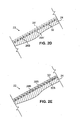
- FIG. 2D is an enlarged cross-sectional view of the airfoil 22 at region II of FIG. 1B after a new structural layer 32 has been applied to the surface of the parent material 24 at the reduced contour 26A (designated in FIG. 2D as location 26A').
- a new contour boundary 26B is defined at an exterior surface of the new structural layer, and the location of the new contour boundary 26B corresponds substantially to the original contour boundary 26 and thus also to the original blueprint specifications.
- the new structural layer 32 can be deposited in a number of different ways in alternative embodiments of the present repair.
- Directed vapor deposition is one suitable process that involves vaporizing a material from multiple crucibles using an electron beam and then condensing the vaporized material on a desired component inside a chamber, much like with electron beam physical vapor deposition (EB-PVD) processes.
- EB-PVD electron beam physical vapor deposition
- the component on which the vapor condenses can be rotated to provide even coating.
- DVD further involves the use of a carrier gas jet of an inert carrier gas (e.g., helium) to direct vaporized material to surfaces of the target component where condensation occurs.
- an inert carrier gas e.g., helium
- the carrier gas jet is typically a single gas stream provided either coaxially with the vaporized material or perpendicular to the flow of the vaporized material.
- An advantage of the DVD process is that it permits complex alloy chemistries of the new structural layer 32 to be deposited on the parent material 24, making the process well-suited for applying nickel-based superalloy materials without disrupting the complex chemistries of those alloys.
- applying material of the new structural layer 32 using a DVD process can involve a number of unique steps that can be used as desired with particular components. For example, a mask can be positioned relative to a selected first portion of a surface where material will be applied while leaving another portion of the surface uncovered in order to reduce the amount of material applied to the first portion of the surface covered by the mask.
- a secondary carrier gas jet can be provided to direct material vapor to areas that would otherwise be concealed or hidden from a single coaxial carrier gas jet, which may be helpful when "build-up" material is applied to components having complex geometries. Also, a component where condensation will occur can be charged and the material vapor cloud ionized in order to facilitate the DVD process.
- Plating is a well-known process that provides an alternative method for depositing material of the new structural layer 32.
- Plating is well suited to applications involving materials comprising single-element metals or relatively simple alloys.
- Known types of plating process include electroplating, sputtering, and other thin film deposition techniques. Electroplating is perhaps the most basic type of plating process, and, in the present context, involves supplying a metallic coating material that acts as an anode and charging the parent material 24 such that it acts as a cathode. When placed in an ionic aqueous solution and current is applied between the anode and cathode, material is plated onto the cathode to form the new structural layer 32 on the parent material 24.
- thickness of the new structural layer 32 can be controlled using weight gain analysis.
- the process of weight gain analysis involves performing a material application to a scrap part (e.g., using the DVD process) and destructively analyzing the scrap part to correlate the thickness of the applied material as a function of weight gain to the scrap part. Thickness of the new structural layer 32 as applied can be determined through nondestructive weight gain measurements of the turbine blade 20 that are correlated to measurements from the scrap part.
- the weight gain analysis correlation can be periodically re-determined to ensure desired process tolerances are met over time. In this way, application of the new structural layer 32 can be controlled so as to produce the new contour boundary 26B at substantially the same dimensions as the original contour boundary 26.
- a new aluminide coating layer is applied to the surface of the new structural layer 32 defined at the new contour boundary 26B.
- the new aluminide coating layer can be applied in a well-known manner, and can be applied in substantially the same manner and to substantially the same depth as during original fabrication of the blade 20.
- Application of the new aluminide coating layer forms a new diffusion layer.
- Heat treatment can be performed on the airfoil 22 before and/or after application of the new aluminide layer, in order to provide desired microstructures and other properties. For example, heat treatment can help provide substantially the same microstructure in the new structural layer 32 as in the parent material 24.
- FIG. 2E is an enlarged cross-sectional view of the airfoil 22 at region II of FIG. 1B upon completion of the repair process of the present invention.
- a new aluminide coating layer 28B is located on the surface of the new structural layer defined by the new contour boundary 26B.
- Application of the new aluminide coating layer 28B forms a new diffusion layer 30B in at least a portion of the new structural layer 32.
- the new diffusion layer 30B may extend through only a portion of the new structural layer 32, through substantially the entire new structural layer 32, or past the new structural layer 32 and into the parent material 24.
- the new diffusion layer 30B will typically have a depth that is approximately the same as the depth of the new structural layer 32 when the new aluminide coating layer 28B has a composition and application method similar to that of original fabrication.
- the turbine blade 20 Upon completion of repairs according to the present invention, the turbine blade 20 can be returned to service. It is contemplated that upon further use in service, the turbine blade 20 may require further repairs to replace the aluminide coating again. In that instance, the repair process described above can be repeated. In that context, any new structural layer 32 from previous repairs can be considered an integral part of the parent material 24 subject to partial or complete removal and the reapplication of additional new layers thereupon.
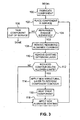
- FIG. 3 is a flow chart that details the repair process described above.
- the process begins with the original fabrication of a gas turbine engine component (step 100).
- the component is then placed in service in a gas turbine engine (step 102).
- the component is inspected to determine if the component has sustained any damage, either due to normal wear or other causes, that makes replacement of its aluminide coating desirable (step 104).
- This inspection takes into account repairable limits of the present repair process. Any component deemed to be outside of repairable limits is generally taken out of service (step 106), and can be scrapped or salvaged.
- the next step is to remove remaining aluminide coatings from the component (step 108), and to remove the existing diffusion layer from the parent material of the component (step 110).
- step 112 another inspection is performed, for instance using known ultrasonic inspection techniques, to determine if the reduced contour of the component (i.e., the residual wall thickness of the component) is below allowed limits (step 112). Allowed limits are generally specified by original component specifications and repair manuals. If the reduced contour is below allowed limits, a new structural layer of "build-up" material is applied to the remaining parent material of the component in order to restore an original blueprint contour to the component. (step 114).
- the new "build-up" material can be a substantially homogeneous material of substantially the same chemical composition as the parent material.
- the new "build-up” material can be applied at step 114 using directed vapor deposition (DVD), plating, or other processes.
- heat treatment is performed to provide a microstructure to the new structural layer that substantially matches a microstructure of the parent material (step 116). Then a new aluminide coating is applied over the new structural layer (step 118). It should be noted that in alternative embodiments, the heat treatment step can be omitted or performed at a different point during the repair process.
- a new aluminide coating can be applied to the parent material (step 118) without the application of any "build-up" material.
- the steps required to apply the "build-up" material can be avoided in some situations to reduce costs and simplify repairs.
- the component can be returned to service (step 102). After the repaired component has returned to service, subsequent repairs can be repeatedly performed on the component, at later occasions, in substantially the same manner.
- the aluminide coatings used according to the present invention can have nearly any composition, and replacements coatings can differ from original coatings as desired.
- the processes used for repair steps such as applying new structural "build-up" layers and applying the aluminide coatings can vary as desired for particular applications.
- the present repair can be performed in conjunction with any other repairs desired to be performed on a particular component.
Landscapes
- Chemical & Material Sciences (AREA)
- Engineering & Computer Science (AREA)
- Mechanical Engineering (AREA)
- Materials Engineering (AREA)
- Chemical Kinetics & Catalysis (AREA)
- Metallurgy (AREA)
- Organic Chemistry (AREA)
- General Engineering & Computer Science (AREA)
- Turbine Rotor Nozzle Sealing (AREA)
- Application Of Or Painting With Fluid Materials (AREA)
- Other Surface Treatments For Metallic Materials (AREA)
Abstract
Description
- The present invention relates to repairs of gas turbine engine components, and more particularly to repairs for gas turbine engine components having aluminide coatings.
- Components of gas turbine engines, such as airfoils, transition ducts and other parts, frequently are provided with aluminide coatings to promote corrosion and oxidation resistance. Aluminide coatings include a broad variety of coating compounds that include aluminum with at least one other more electropositive element. The parent materials of these coated engine components are frequently nickel- or cobalt-based superalloys. When the aluminide coatings are applied to the parent alloys, a diffusion layer is formed in the parent alloys beneath the exterior aluminide coating layers.
- During operation of the engine, the coated components may become worn or damaged, due to oxidation, erosion, foreign object damage, or other factors. Over time, it may become necessary to repair or replace the aluminide coating in order to continue using the worn or damaged components. Over the full useful life of a particular component, numerous coating repairs may need to be performed in order to allow continued use. These processes typically involve first stripping any remaining coatings. When the remaining coatings are removed, the diffusion layer must also be removed in order to prevent the formation of a deleterious microstructure in the replacement coating. A new, replacement aluminide coating is then applied.
- A problem with known repairs for aluminide coated components is that removal of the diffusion layer results in a reduction of the component contour (or envelope) from original blueprint dimensions. On average, about 1.5 mils (38 µm) of parent alloy is lost on each exterior surface of the parent material where such coating repairs are performed that remove the diffusion layer (see
FIG. 2C ). Loss of parent material can reduce the component contour (or envelope) below minimum allowable limits, especially in situations where repeated repairs are performed on a given component over time, which generally necessitates scrapping the component. There are known repairs that attempt to restore dimensions of components after a diffusion layer has been removed. However, those methods deal only with the application of non-structural layers, and do not restore the blueprint contour of the structural materials of the component. - It is desired to provide a repair method that expands repairable limits for gas turbine engine components and lessens the need to reduce structural contours (or envelopes) of gas turbine engine components in order to repair or replace aluminide coatings.
- A method of repairing a component of a gas turbine engine that includes a metallic substrate, an existing aluminide coating, and a diffusion layer formed in the metallic substrate adjacent to the coating. The method includes removing at least a portion of the existing aluminide coating, removing material forming the diffusion layer, applying a new metallic layer to the metallic substrate, and applying a new aluminide coating over the new metallic layer to form a new diffusion layer in the new metallic layer. The new metallic layer is a substantially homogeneous material that is substantially similar in chemical composition to that of the metallic substrate, and the new metallic layer forms a structural layer having a thickness selected to provide a specified contour to the component.
-
-
FIG. 1A is a side view of a turbine blade. -
FIG. 1B is a cross sectional view of the turbine blade, taken along line A-A ofFIG. 1 . -
FIG. 2A is an enlarged cross-sectional view of region II ofFIG. 1B . -
FIG. 2B is an enlarged cross-sectional view of region II ofFIG. 1B during a repair process according to the present invention. -
FIG. 2C is an enlarged cross-sectional view of region II ofFIG. 1B after a prior art repair process has been performed. -
FIG. 2D is an enlarged cross-sectional view of region II ofFIG. 1B during the repair process of the present invention. -
FIG. 2E is an enlarged cross-sectional view of region II ofFIG. 1B upon completion of the repair process of the present invention. -
FIG. 3 is a flow chart of a repair process according to the present invention. - In general, the present invention relates to repairs of gas turbine engine components having aluminide coatings, such as coatings that include the beta NiAl phase, the gamma-prime Ni3Al phase, the gamma Ni phase, and any combination thereof, and each of those phases can be solid solutions that contain, for example, aluminum, cobalt, chrome, yttrium, hafnium, silicon, tantalum, tungsten, rhenium, molybdenum or ruthenium. The repair involves removing existing coatings as well as a diffusion layer formed in a metallic parent material. A new, structural "build-up" material is applied to the remaining parent material to restore an original blueprint contour of the component, which helps to compensate for the loss of material in the diffusion layer. Then a new aluminide coating is applied over the new "build-up" material, creating a new diffusion layer. The new "build-up" material can be a substantially homogeneous material of substantially the same chemical composition as the metallic parent material. The new "build-up" material can be applied using directed vapor deposition (DVD) or plating processes.
-
FIG. 1A is a side view of anexemplary turbine blade 20 for a gas turbine engine.FIG. 1B is a cross sectional view of theturbine blade 20, taken along line A-A ofFIG. 1 . Theturbine blade 20 includes anairfoil section 22 that has a relatively uniform aluminide coating applied over substantially an entire exterior surface of at least theairfoil section 22. Theturbine blade 20, including theairfoil section 22, is made of a metallic parent material that can be a nickel-based superalloy, although other metals or alloys can be used in alternative embodiments. The metallic parent material defines a contour (or envelope) of theairfoil 22, which corresponds to original blueprint specifications when theturbine blade 20 is originally fabricated. Theturbine blade 20 is shown as an example of a component that frequently includes an aluminide coating. However, it should be noted that the illustrated configuration of theturbine blade 20 is merely exemplary, and the present invention applies to turbine blades of any configuration. Moreover, it should be recognized that other gas turbine engine components can have aluminide coatings, and the present invention is not limited to any particular component or set of components. -
FIG. 2A is an enlarged cross-sectional view of region II of theturbine blade 20 ofFIG. 1B , at a convex suction surface of theairfoil 22. As shown inFIG. 2A , theairfoil 22 includes aparent material 24 that extends to acomponent contour boundary 26, analuminide coating layer 28, and adiffusion layer 30 formed in theparent material 24. Thealuminide coating layer 28 can be a single homogeneous layer, or can comprise multiple layers that can be distinguished by their microstructures (thealuminide coating layer 28 is represented as a single layer inFIG. 2A for simplicity). Thealuminide coating layer 28 can also serve as a bond coat for an optional primary outer layer (the optional primary outer layer is not depicted inFIG. 2A ). Thediffusion layer 30 is formed in theparent material 24 when thealuminide coating layer 28 is applied, and the depth or thickness of thediffusion layer 30 will vary according to the materials and procedures used to apply thealuminide coating layer 28. Thecontour boundary 26 is defined at an exterior boundary of thediffusion layer 30.FIG. 2A illustrates the configuration of theairfoil 22 after original fabrication, at original blueprint specifications. Therefore,contour boundary 26 corresponds to original blueprint dimensions. However, those of ordinary skill in the art will recognize that the layers shown schematically in the accompanying drawings are simplified, and on actual components may be less distinct and less uniform than depicted. Moreover, while only a portion of turbine blade is shown in detail, the present repair can apply to any exterior surface of theblade 20, although typically aluminide coatings are only applied to theairfoil 22. It should be also noted that thealuminide coating layer 28 is shown and described herein as an outwardly grown coating. However, the present invention applies equally to inwardly grown coatings where the original contour boundary is defined at the outermost surface of thealuminide coating layer 28. - The
turbine blade 20 can be placed in service in a gas turbine engine. As a result of such use, theairfoil section 22 of theblade 20 is prone to wear and damage. After being placed in service, theblade 20 can be inspected in order to make a determination as to whether replacement of thealuminide coating layer 28 is necessary or desired. - Once repair has been undertaken, a preliminary step is to remove any remaining portions of the
aluminide coating layer 28, as well as to remove material forming thediffusion layer 30. It is generally necessary to remove the material of thediffusion layer 30 in order to prevent the formation of a deleterious microstructure in the replacement aluminide coating. Material removal can be accomplished using known chemical or mechanical methods. Removal of the originalaluminide coating layer 28 and thediffusion layer 30 can be accomplished with a single removal process that removes bothlayers layers -
FIG. 2B is an enlarged cross-sectional view of theairfoil 22 at region II ofFIG. 1B after thealuminide coating layer 28 and thediffusion layer 30 ofFIG. 2A have been removed. A new reducedcontour boundary 26A of theparent material 24 is formed that is smaller than theoriginal contour boundary 26 prior to removal of material, which is designated in phantom at boundary line 26' for reference. Moreover, region 28' corresponds to the location of the originalaluminide coating layer 28 prior to removal. - At this point it is helpful to understand prior art repair methods.
FIG. 2C is an enlarged cross-sectional view of region II ofFIG. 1B after a prior art repair process has been performed on theairfoil 22. With such a prior art repair method, a newaluminide coating layer 28A is applied directly to the reducedcontour boundary 26A at a thickness that is identical to that of the originalaluminide coating layer 28. The application of the newaluminide coating layer 28A forms anew diffusion layer 30A in theoriginal parent material 24. This results in a net loss of component contour dimensions, and will eventually reduce the resultant component contour (i.e., reducedcontour boundary 26A) below allowable limits, especially if such a repair is repeated multiple times on the same component over time. - According to the present invention, the
airfoil 22 is essentially restored to theoriginal contour boundary 26 before a new aluminide coating is applied. Theoriginal contour boundary 26 is restored by applying a new structural "build-up" layer upon the surface of theparent material 24 at the reducedcontour boundary 26A. The new structural layer is made up of a substantially homogeneous metallic material that is substantially similar in chemical composition to theparent material 24. For example, the new structural layer and theparent material 24 can both be made of the same hickel-based superalloy. -
FIG. 2D is an enlarged cross-sectional view of theairfoil 22 at region II ofFIG. 1B after a newstructural layer 32 has been applied to the surface of theparent material 24 at the reducedcontour 26A (designated inFIG. 2D aslocation 26A'). Anew contour boundary 26B is defined at an exterior surface of the new structural layer, and the location of thenew contour boundary 26B corresponds substantially to theoriginal contour boundary 26 and thus also to the original blueprint specifications. - The new
structural layer 32 can be deposited in a number of different ways in alternative embodiments of the present repair. Directed vapor deposition (DVD) is one suitable process that involves vaporizing a material from multiple crucibles using an electron beam and then condensing the vaporized material on a desired component inside a chamber, much like with electron beam physical vapor deposition (EB-PVD) processes. The component on which the vapor condenses can be rotated to provide even coating. DVD further involves the use of a carrier gas jet of an inert carrier gas (e.g., helium) to direct vaporized material to surfaces of the target component where condensation occurs. The carrier gas jet is typically a single gas stream provided either coaxially with the vaporized material or perpendicular to the flow of the vaporized material. An advantage of the DVD process is that it permits complex alloy chemistries of the newstructural layer 32 to be deposited on theparent material 24, making the process well-suited for applying nickel-based superalloy materials without disrupting the complex chemistries of those alloys. In addition, applying material of the newstructural layer 32 using a DVD process can involve a number of unique steps that can be used as desired with particular components. For example, a mask can be positioned relative to a selected first portion of a surface where material will be applied while leaving another portion of the surface uncovered in order to reduce the amount of material applied to the first portion of the surface covered by the mask. As another example, a secondary carrier gas jet can be provided to direct material vapor to areas that would otherwise be concealed or hidden from a single coaxial carrier gas jet, which may be helpful when "build-up" material is applied to components having complex geometries. Also, a component where condensation will occur can be charged and the material vapor cloud ionized in order to facilitate the DVD process. - Plating is a well-known process that provides an alternative method for depositing material of the new
structural layer 32. Plating is well suited to applications involving materials comprising single-element metals or relatively simple alloys. Known types of plating process include electroplating, sputtering, and other thin film deposition techniques. Electroplating is perhaps the most basic type of plating process, and, in the present context, involves supplying a metallic coating material that acts as an anode and charging theparent material 24 such that it acts as a cathode. When placed in an ionic aqueous solution and current is applied between the anode and cathode, material is plated onto the cathode to form the newstructural layer 32 on theparent material 24. - With any method used to apply the material of the new
structural layer 32, thickness of the newstructural layer 32 can be controlled using weight gain analysis. The process of weight gain analysis involves performing a material application to a scrap part (e.g., using the DVD process) and destructively analyzing the scrap part to correlate the thickness of the applied material as a function of weight gain to the scrap part. Thickness of the newstructural layer 32 as applied can be determined through nondestructive weight gain measurements of theturbine blade 20 that are correlated to measurements from the scrap part. The weight gain analysis correlation can be periodically re-determined to ensure desired process tolerances are met over time. In this way, application of the newstructural layer 32 can be controlled so as to produce thenew contour boundary 26B at substantially the same dimensions as theoriginal contour boundary 26. - After the new
structural layer 32 has been applied, a new aluminide coating layer is applied to the surface of the newstructural layer 32 defined at thenew contour boundary 26B. The new aluminide coating layer can be applied in a well-known manner, and can be applied in substantially the same manner and to substantially the same depth as during original fabrication of theblade 20. Application of the new aluminide coating layer forms a new diffusion layer. Heat treatment can be performed on theairfoil 22 before and/or after application of the new aluminide layer, in order to provide desired microstructures and other properties. For example, heat treatment can help provide substantially the same microstructure in the newstructural layer 32 as in theparent material 24. -
FIG. 2E is an enlarged cross-sectional view of theairfoil 22 at region II ofFIG. 1B upon completion of the repair process of the present invention. A newaluminide coating layer 28B is located on the surface of the new structural layer defined by thenew contour boundary 26B. Application of the newaluminide coating layer 28B forms anew diffusion layer 30B in at least a portion of the newstructural layer 32. For particular applications, thenew diffusion layer 30B may extend through only a portion of the newstructural layer 32, through substantially the entire newstructural layer 32, or past the newstructural layer 32 and into theparent material 24. However, thenew diffusion layer 30B will typically have a depth that is approximately the same as the depth of the newstructural layer 32 when the newaluminide coating layer 28B has a composition and application method similar to that of original fabrication. - Upon completion of repairs according to the present invention, the
turbine blade 20 can be returned to service. It is contemplated that upon further use in service, theturbine blade 20 may require further repairs to replace the aluminide coating again. In that instance, the repair process described above can be repeated. In that context, any newstructural layer 32 from previous repairs can be considered an integral part of theparent material 24 subject to partial or complete removal and the reapplication of additional new layers thereupon. -
FIG. 3 is a flow chart that details the repair process described above. The process begins with the original fabrication of a gas turbine engine component (step 100). The component is then placed in service in a gas turbine engine (step 102). After some period of use, the component is inspected to determine if the component has sustained any damage, either due to normal wear or other causes, that makes replacement of its aluminide coating desirable (step 104). This inspection takes into account repairable limits of the present repair process. Any component deemed to be outside of repairable limits is generally taken out of service (step 106), and can be scrapped or salvaged. If repairable damage is identified, the next step is to remove remaining aluminide coatings from the component (step 108), and to remove the existing diffusion layer from the parent material of the component (step 110). At this point, another inspection is performed, for instance using known ultrasonic inspection techniques, to determine if the reduced contour of the component (i.e., the residual wall thickness of the component) is below allowed limits (step 112). Allowed limits are generally specified by original component specifications and repair manuals. If the reduced contour is below allowed limits, a new structural layer of "build-up" material is applied to the remaining parent material of the component in order to restore an original blueprint contour to the component. (step 114). As noted above, the new "build-up" material can be a substantially homogeneous material of substantially the same chemical composition as the parent material. The new "build-up" material can be applied atstep 114 using directed vapor deposition (DVD), plating, or other processes. Next, heat treatment is performed to provide a microstructure to the new structural layer that substantially matches a microstructure of the parent material (step 116). Then a new aluminide coating is applied over the new structural layer (step 118). It should be noted that in alternative embodiments, the heat treatment step can be omitted or performed at a different point during the repair process. - If at
step 112 it is determined that the reduced contour is not below allowed limits, a new aluminide coating can be applied to the parent material (step 118) without the application of any "build-up" material. Thus, the steps required to apply the "build-up" material can be avoided in some situations to reduce costs and simplify repairs. - Once all repairs are completed, the component can be returned to service (step 102). After the repaired component has returned to service, subsequent repairs can be repeatedly performed on the component, at later occasions, in substantially the same manner.
- Although the present invention has been described with reference to preferred embodiments, workers skilled in the art will recognize that changes can be made in form and detail without departing from the scope of the invention, which is defined by the claims and their equivalents. For instance, the aluminide coatings used according to the present invention can have nearly any composition, and replacements coatings can differ from original coatings as desired. Moreover, the processes used for repair steps such as applying new structural "build-up" layers and applying the aluminide coatings can vary as desired for particular applications. In addition, it should be recognized that the present repair can be performed in conjunction with any other repairs desired to be performed on a particular component.
Claims (14)
- A method of repairing a component of a gas turbine engine that includes a metallic substrate (24), an existing aluminide coating (28), and a diffusion layer (30) formed in the metallic substrate adjacent to the coating, the method comprising:removing at least a portion of the existing aluminide coating (28);removing material forming the diffusion layer (30);applying a new metallic layer (32) to the metallic substrate, wherein the new metallic layer comprises a substantially homogeneous material that is substantially similar in chemical composition to that of the metallic substrate, and wherein the new metallic layer forms a structural layer having a thickness selected to provide a specified contour to the component; andapplying a new aluminide coating (28B) over the new metallic layer (32), wherein applying the new aluminide coating forms a new diffusion layer (30B) in the new metallic layer.
- The method of claim 1, wherein the new metallic layer (32) is applied to the metallic substrate (24) using a directed vapor deposition process.
- The method of claim 2, wherein the step of applying the new metallic layer to the metallic substrate using the directed vapor deposition process comprises:providing a first carrier gas stream of an inert gas;providing a second carrier gas stream of an inert gas, wherein the second carrier gas stream directs new metallic material to a non-line-of-sight surface of the metallic substrate.
- The method of claim 2 or 3 and further comprising:positioning a mask relative to a first surface region of the metallic substrate while leaving a second surface region uncovered, wherein the mask reduces the thickness of the new metallic layer at the first surface region relative to the second surface region.
- The method of claim 1, wherein the new metallic layer (32) is applied to the metallic substrate (24) using a plating process.
- The method of any preceding claim, wherein the metallic substrate comprises a nickel-based superalloy.
- The method of any preceding claim, wherein the material forming the diffusion layer (30) is removed by chemical means.
- The method of any preceding claim and further comprising:heat treating the metallic substrate (24) and the new metallic layer (32) such that the microstructure of the new metallic layer is substantially similar to that of the metallic substrate.
- A repaired apparatus for a gas turbine engine, the apparatus comprising:a previously-in-service component substrate comprising a metallic parent material (24) and having an exterior dimension less than a predetermined final exterior dimension;a structural layer of new metallic material (32) applied to the substrate to build-up the component substrate to the predetermined final exterior dimension, wherein the new metallic material has a substantially homogeneous chemical composition that is substantially similar to that of the metallic parent material; anda new aluminide coating (28B) applied over the layer of new metallic material, wherein a diffusion region (30B) is formed in the layer of new metallic material (32).
- The apparatus of claim 9, wherein the component substrate comprises an airfoil.
- The apparatus of claim 9 or 10, wherein the parent material comprises a nickel-based superalloy.
- The apparatus of claim 9, 10 or 11, wherein the structural layer of new metallic material comprises a nickel-based superalloy.
- The apparatus of claim 9, 10, 11 or 12 wherein the aluminide layer comprises:a base coat; anda primary layer located on top of the base coat.
- The apparatus of any of claims 9 to 13 wherein the depth of the diffusion region (30B) is substantially equal to the thickness of the layer of new metallic material (32).
Applications Claiming Priority (1)
| Application Number | Priority Date | Filing Date | Title |
|---|---|---|---|
| US11/805,960 US20080292903A1 (en) | 2007-05-25 | 2007-05-25 | Coated gas turbine engine component repair |
Publications (2)
| Publication Number | Publication Date |
|---|---|
| EP1995346A2 true EP1995346A2 (en) | 2008-11-26 |
| EP1995346A3 EP1995346A3 (en) | 2010-07-14 |
Family
ID=39620776
Family Applications (1)
| Application Number | Title | Priority Date | Filing Date |
|---|---|---|---|
| EP08251806A Withdrawn EP1995346A3 (en) | 2007-05-25 | 2008-05-23 | Coated gas turbine engine component repair |
Country Status (3)
| Country | Link |
|---|---|
| US (2) | US20080292903A1 (en) |
| EP (1) | EP1995346A3 (en) |
| SG (1) | SG148113A1 (en) |
Cited By (2)
| Publication number | Priority date | Publication date | Assignee | Title |
|---|---|---|---|---|
| EP2453030A1 (en) * | 2010-11-08 | 2012-05-16 | United Technologies Corporation | A method for repairing/refurbishing/creating a turbine engine component |
| EP2801639A1 (en) * | 2013-05-08 | 2014-11-12 | Siemens Aktiengesellschaft | Welding of calorised components and a calorised component |
Families Citing this family (7)
| Publication number | Priority date | Publication date | Assignee | Title |
|---|---|---|---|---|
| SG155778A1 (en) * | 2008-03-10 | 2009-10-29 | Turbine Overhaul Services Pte | Method for diffusion bonding metallic components with nanoparticle foil |
| US8646511B2 (en) * | 2010-08-04 | 2014-02-11 | Siemens Energy, Inc. | Component with inspection-facilitating features |
| US8541069B2 (en) * | 2011-04-11 | 2013-09-24 | United Technologies Corporation | Method of guided non-line of sight coating |
| US20140174091A1 (en) * | 2012-12-21 | 2014-06-26 | United Technologies Corporation | Repair procedure for a gas turbine engine via variable polarity welding |
| RU2015131619A (en) * | 2013-01-31 | 2017-03-10 | Сименс Энерджи, Инк. | LOCALIZED REPAIR OF SUPER ALLOY COMPONENT |
| EP3096920A4 (en) * | 2014-01-24 | 2017-03-01 | United Technologies Corporation | Additive repair for combustor liner panels |
| US9321115B2 (en) * | 2014-02-05 | 2016-04-26 | Alstom Technologies Ltd | Method of repairing a transition duct side seal |
Citations (3)
| Publication number | Priority date | Publication date | Assignee | Title |
|---|---|---|---|---|
| EP1533396A2 (en) * | 2003-11-13 | 2005-05-25 | General Electric Company | Method for repairing coated components using NiAl bond coats |
| EP1752559A2 (en) * | 2005-08-01 | 2007-02-14 | General Electric Company | Method for restoring portion of turbine component |
| EP1944387A1 (en) * | 2006-12-29 | 2008-07-16 | General Electric Company | System and method for restoring or regenerating an article |
Family Cites Families (26)
| Publication number | Priority date | Publication date | Assignee | Title |
|---|---|---|---|---|
| US3979273A (en) * | 1975-05-27 | 1976-09-07 | United Technologies Corporation | Method of forming aluminide coatings on nickel-, cobalt-, and iron-base alloys |
| DE3585901D1 (en) * | 1984-02-13 | 1992-05-27 | Iii Jerome J Schmitt | METHOD AND DEVICE FOR GAS RAY DEPOSITION OF CONDUCTIVE AND DIELECTRIC THICKEN FILMS AND PRODUCTS MADE THEREOF. |
| US4726101A (en) * | 1986-09-25 | 1988-02-23 | United Technologies Corporation | Turbine vane nozzle reclassification |
| US5356672A (en) * | 1990-05-09 | 1994-10-18 | Jet Process Corporation | Method for microwave plasma assisted supersonic gas jet deposition of thin films |
| US5142778A (en) * | 1991-03-13 | 1992-09-01 | United Technologies Corporation | Gas turbine engine component repair |
| US5437737A (en) * | 1994-02-07 | 1995-08-01 | United Technologies Corporation | Repair coating for superalloy articles, such as gas turbine engine components |
| US5534314A (en) * | 1994-08-31 | 1996-07-09 | University Of Virginia Patent Foundation | Directed vapor deposition of electron beam evaporant |
| US5571332A (en) * | 1995-02-10 | 1996-11-05 | Jet Process Corporation | Electron jet vapor deposition system |
| US5736073A (en) * | 1996-07-08 | 1998-04-07 | University Of Virginia Patent Foundation | Production of nanometer particles by directed vapor deposition of electron beam evaporant |
| US5806751A (en) * | 1996-10-17 | 1998-09-15 | United Technologies Corporation | Method of repairing metallic alloy articles, such as gas turbine engine components |
| US6049978A (en) * | 1996-12-23 | 2000-04-18 | Recast Airfoil Group | Methods for repairing and reclassifying gas turbine engine airfoil parts |
| US20040031140A1 (en) * | 1996-12-23 | 2004-02-19 | Arnold James E. | Methods for salvaging a cast article |
| US6233822B1 (en) * | 1998-12-22 | 2001-05-22 | General Electric Company | Repair of high pressure turbine shrouds |
| US6253441B1 (en) * | 1999-04-16 | 2001-07-03 | General Electric Company | Fabrication of articles having a coating deposited through a mask |
| US6305077B1 (en) * | 1999-11-18 | 2001-10-23 | General Electric Company | Repair of coated turbine components |
| US6509067B2 (en) * | 2000-04-28 | 2003-01-21 | Jet Process Corporation | Method and apparatus for the deposition of metal nanoclusters and films on a substrate |
| CA2411174C (en) * | 2000-05-23 | 2008-05-06 | James F. Groves | A process and apparatus for plasma activated deposition in a vacuum |
| US7879411B2 (en) * | 2001-04-30 | 2011-02-01 | University Of Virginia Patent Foundation | Method and apparatus for efficient application of substrate coating |
| EP1436441B2 (en) * | 2001-09-10 | 2012-11-28 | University Of Virginia Patent Foundation | Method for applying metallic alloy coatings and coated component |
| WO2003091473A1 (en) * | 2002-04-25 | 2003-11-06 | University Of Virginia Patent Foundation | Apparatus and method for high rate uniform coating, including non-line of sight |
| US7060366B2 (en) * | 2003-02-19 | 2006-06-13 | General Electric Company | Article including a substrate with a metallic coating and a chromium-aluminide protective coating thereon, and its preparation and use in component restoration |
| US8122600B2 (en) * | 2003-03-03 | 2012-02-28 | United Technologies Corporation | Fan and compressor blade dovetail restoration process |
| WO2005047202A2 (en) * | 2003-07-29 | 2005-05-26 | University Of Virginia Patent Foundation | Method for application of a thermal barrier coating and resultant structure thereof |
| US7078073B2 (en) * | 2003-11-13 | 2006-07-18 | General Electric Company | Method for repairing coated components |
| WO2005089107A2 (en) * | 2004-01-08 | 2005-09-29 | University Of Virginia Patent Foundation | Apparatus and method for applying coatings onto the interior surfaces of components and related structures produced therefrom |
| US20080160213A1 (en) * | 2006-12-29 | 2008-07-03 | Michael Patrick Maly | Method for restoring or regenerating an article |
-
2007
- 2007-05-25 US US11/805,960 patent/US20080292903A1/en not_active Abandoned
-
2008
- 2008-05-12 SG SG200803634-5A patent/SG148113A1/en unknown
- 2008-05-23 EP EP08251806A patent/EP1995346A3/en not_active Withdrawn
-
2010
- 2010-09-15 US US12/882,380 patent/US20110167634A1/en not_active Abandoned
Patent Citations (3)
| Publication number | Priority date | Publication date | Assignee | Title |
|---|---|---|---|---|
| EP1533396A2 (en) * | 2003-11-13 | 2005-05-25 | General Electric Company | Method for repairing coated components using NiAl bond coats |
| EP1752559A2 (en) * | 2005-08-01 | 2007-02-14 | General Electric Company | Method for restoring portion of turbine component |
| EP1944387A1 (en) * | 2006-12-29 | 2008-07-16 | General Electric Company | System and method for restoring or regenerating an article |
Non-Patent Citations (1)
| Title |
|---|
| YU Z ET AL: "NiAl bond coats made by a directed vapor deposition approach" MATERIALS SCIENCE AND ENGINEERING A: STRUCTURAL MATERIALS:PROPERTIES, MICROSTRUCTURE & PROCESSING, LAUSANNE, CH LNKD- DOI:10.1016/J.MSEA.2004.11.017, vol. 394, no. 1-2, 15 March 2005 (2005-03-15), pages 43-52, XP025303873 ISSN: 0921-5093 [retrieved on 2005-03-15] * |
Cited By (4)
| Publication number | Priority date | Publication date | Assignee | Title |
|---|---|---|---|---|
| EP2453030A1 (en) * | 2010-11-08 | 2012-05-16 | United Technologies Corporation | A method for repairing/refurbishing/creating a turbine engine component |
| US10173291B2 (en) | 2010-11-08 | 2019-01-08 | United Technologies Corporation | Low and extra low sulfur alloys for repair |
| EP2801639A1 (en) * | 2013-05-08 | 2014-11-12 | Siemens Aktiengesellschaft | Welding of calorised components and a calorised component |
| WO2014180652A1 (en) * | 2013-05-08 | 2014-11-13 | Siemens Aktiengesellschaft | Welding of alitized components and an alitized component |
Also Published As
| Publication number | Publication date |
|---|---|
| EP1995346A3 (en) | 2010-07-14 |
| US20110167634A1 (en) | 2011-07-14 |
| SG148113A1 (en) | 2008-12-31 |
| US20080292903A1 (en) | 2008-11-27 |
Similar Documents
| Publication | Publication Date | Title |
|---|---|---|
| US20110167634A1 (en) | Coated gas turbine engine component repair | |
| US6274193B1 (en) | Repair of a discrete selective surface of an article | |
| US5813118A (en) | Method for repairing an air cooled turbine engine airfoil | |
| EP1533396B1 (en) | Method for repairing coated components using NiAl bond coats | |
| US6605364B1 (en) | Coating article and method for repairing a coated surface | |
| EP1118695B1 (en) | Method of removing a thermal barrier coating | |
| US5972424A (en) | Repair of gas turbine engine component coated with a thermal barrier coating | |
| US7371426B2 (en) | Method for repairing components using environmental bond coatings and resultant repaired components | |
| EP1236812B1 (en) | Method for refurbishing a coating including a thermally grown oxide | |
| EP2191930A2 (en) | Repair Method For TBC Coated Turbine Components | |
| EP2631325A2 (en) | Coating and coating method for gas turbine component | |
| EP2848356B1 (en) | A method for repairing a turbine component wherein damaged material is removed and a plug with improved material properties is inserted and a corresponding repaired component | |
| JP2006207030A (en) | Repair and reclassification of superalloy component | |
| JP2004525254A (en) | How to remove ceramic film | |
| EP1944387A1 (en) | System and method for restoring or regenerating an article | |
| US8252376B2 (en) | Method for restoring the microstructure of a textured article and for refurbishing a gas turbine blade or vane | |
| US20080160213A1 (en) | Method for restoring or regenerating an article | |
| US6482470B1 (en) | Diffusion aluminide coated metallic substrate including a thin diffusion portion of controlled thickness | |
| EP1123987A1 (en) | Repairable diffusion aluminide coatings | |
| US6565672B2 (en) | Fabrication of an article having a protective coating with a flattened, pre-oxidized protective-coating surface | |
| US6652982B2 (en) | Fabrication of an article having a protective coating with a flat protective-coating surface and a low sulfur content | |
| EP1950320B1 (en) | Method for restoring or regenerating an article and restored regenerated article | |
| US12138669B2 (en) | Method of removing contaminants from a diffusion-coated component | |
| US20220288653A1 (en) | Method of removing contaminants from a diffusion-coated component | |
| US20240375155A1 (en) | Method of removing contaminants from a diffusion-coated component |
Legal Events
| Date | Code | Title | Description |
|---|---|---|---|
| PUAI | Public reference made under article 153(3) epc to a published international application that has entered the european phase |
Free format text: ORIGINAL CODE: 0009012 |
|
| AK | Designated contracting states |
Kind code of ref document: A2 Designated state(s): AT BE BG CH CY CZ DE DK EE ES FI FR GB GR HR HU IE IS IT LI LT LU LV MC MT NL NO PL PT RO SE SI SK TR |
|
| AX | Request for extension of the european patent |
Extension state: AL BA MK RS |
|
| PUAL | Search report despatched |
Free format text: ORIGINAL CODE: 0009013 |
|
| AK | Designated contracting states |
Kind code of ref document: A3 Designated state(s): AT BE BG CH CY CZ DE DK EE ES FI FR GB GR HR HU IE IS IT LI LT LU LV MC MT NL NO PL PT RO SE SI SK TR |
|
| AX | Request for extension of the european patent |
Extension state: AL BA MK RS |
|
| RIC1 | Information provided on ipc code assigned before grant |
Ipc: F01D 5/28 20060101ALI20100609BHEP Ipc: B23P 6/00 20060101ALI20100609BHEP Ipc: C23C 30/00 20060101ALI20100609BHEP Ipc: C23C 28/02 20060101ALI20100609BHEP Ipc: C23C 10/60 20060101ALI20100609BHEP Ipc: C23C 10/48 20060101ALI20100609BHEP Ipc: C23C 10/04 20060101ALI20100609BHEP Ipc: C23C 10/02 20060101AFI20080724BHEP |
|
| 17P | Request for examination filed |
Effective date: 20101230 |
|
| AKX | Designation fees paid |
Designated state(s): DE GB |
|
| GRAP | Despatch of communication of intention to grant a patent |
Free format text: ORIGINAL CODE: EPIDOSNIGR1 |
|
| INTG | Intention to grant announced |
Effective date: 20140806 |
|
| STAA | Information on the status of an ep patent application or granted ep patent |
Free format text: STATUS: THE APPLICATION IS DEEMED TO BE WITHDRAWN |
|
| 18D | Application deemed to be withdrawn |
Effective date: 20141202 |