EP1995210B1 - Kraftstoffabgabevorrichtung mit intelligentem Schalter - Google Patents
Kraftstoffabgabevorrichtung mit intelligentem Schalter Download PDFInfo
- Publication number
- EP1995210B1 EP1995210B1 EP07108732A EP07108732A EP1995210B1 EP 1995210 B1 EP1995210 B1 EP 1995210B1 EP 07108732 A EP07108732 A EP 07108732A EP 07108732 A EP07108732 A EP 07108732A EP 1995210 B1 EP1995210 B1 EP 1995210B1
- Authority
- EP
- European Patent Office
- Prior art keywords
- fuel
- control unit
- switches
- switch
- fuel dispensing
- Prior art date
- Legal status (The legal status is an assumption and is not a legal conclusion. Google has not performed a legal analysis and makes no representation as to the accuracy of the status listed.)
- Not-in-force
Links
- 239000000446 fuel Substances 0.000 title claims description 111
- 238000004891 communication Methods 0.000 claims description 25
- 230000004888 barrier function Effects 0.000 claims description 11
- 238000004880 explosion Methods 0.000 claims description 6
- 238000007789 sealing Methods 0.000 claims description 4
- 230000007480 spreading Effects 0.000 claims description 4
- 230000008859 change Effects 0.000 claims description 2
- 238000000034 method Methods 0.000 description 3
- 229910000831 Steel Inorganic materials 0.000 description 2
- 238000012423 maintenance Methods 0.000 description 2
- 238000004519 manufacturing process Methods 0.000 description 2
- 238000005086 pumping Methods 0.000 description 2
- 239000010959 steel Substances 0.000 description 2
- 230000003213 activating effect Effects 0.000 description 1
- 230000007423 decrease Effects 0.000 description 1
- 230000001419 dependent effect Effects 0.000 description 1
- 238000013461 design Methods 0.000 description 1
- 238000001514 detection method Methods 0.000 description 1
- 238000005553 drilling Methods 0.000 description 1
- 239000002360 explosive Substances 0.000 description 1
- 230000006872 improvement Effects 0.000 description 1
- 230000002779 inactivation Effects 0.000 description 1
- 230000035515 penetration Effects 0.000 description 1
- 238000012545 processing Methods 0.000 description 1
- 230000009993 protective function Effects 0.000 description 1
Images
Classifications
-
- B—PERFORMING OPERATIONS; TRANSPORTING
- B67—OPENING, CLOSING OR CLEANING BOTTLES, JARS OR SIMILAR CONTAINERS; LIQUID HANDLING
- B67D—DISPENSING, DELIVERING OR TRANSFERRING LIQUIDS, NOT OTHERWISE PROVIDED FOR
- B67D7/00—Apparatus or devices for transferring liquids from bulk storage containers or reservoirs into vehicles or into portable containers, e.g. for retail sale purposes
- B67D7/06—Details or accessories
- B67D7/32—Arrangements of safety or warning devices; Means for preventing unauthorised delivery of liquid
- B67D7/34—Means for preventing unauthorised delivery of liquid
-
- B—PERFORMING OPERATIONS; TRANSPORTING
- B67—OPENING, CLOSING OR CLEANING BOTTLES, JARS OR SIMILAR CONTAINERS; LIQUID HANDLING
- B67D—DISPENSING, DELIVERING OR TRANSFERRING LIQUIDS, NOT OTHERWISE PROVIDED FOR
- B67D7/00—Apparatus or devices for transferring liquids from bulk storage containers or reservoirs into vehicles or into portable containers, e.g. for retail sale purposes
- B67D7/06—Details or accessories
- B67D7/32—Arrangements of safety or warning devices; Means for preventing unauthorised delivery of liquid
Definitions
- the present invention relates to a system for providing dispensing of fuel, and to a fuel dispensing unit and a fuel payment terminal comprising such a system.
- Some events that should be detected are related to the operation of the fuel dispensing unit, such as detecting if a fuel dispensing nozzle is lifted from its nozzle boot, what kind of fuel grade is selected for dispensing etc.
- Other events are related to misuse of the dispenser, e.g. attempts to steel fuel.
- switches for fuel dispensing units is that it is hard to use a more common switch design for detecting several different kinds of events, such as lifting a fuel dispensing nozzle, selecting a specific fuel grade, releasing a theft alarm etc.
- anti-theft systems which incorporate some kind of tamper-detecting sensor that breaks a switch which thus gives or breaks a signal between the fuel dispensing unit and a central unit.
- tamper-detecting sensor that breaks a switch which thus gives or breaks a signal between the fuel dispensing unit and a central unit.
- Inactivation involves, for instance, setting a logic variable in the control system of the pump at a certain value so that that pumping is not allowed, or, in a mechanical control system, activating a mechanical stop which physically prevents pumping.
- a drawback of the above-described anti-theft systems is that they still can relatively easily be tampered with so as to allow theft of fuel. By existing components being bypassed, joined with tape, broken to pieces or replaced with other components, the fuel dispensing unit can be started so that theft of fuel can take place.
- a system for providing dispensing of fuel for refuelling vehicles comprising a control unit and at least two switches.
- Each of said switches is connected to the control unit and comprises a microcontroller for storing a unique identifier, which identifier is associated with the switch and readable by the control unit, for allowing the control unit to identify each of the at least two switches.
- Each switch may comprise a power source, for allowing the switch to operate independently of the control unit and thereby, for example, provide for a more versatile and/or tamper-proof implementation of the switch, since the switch is not longer dependant of an external power source.
- Each switch may be configured to store a key which represents a condition were tampering of the fuel system is not detected, which provides a switch-status indicating, for example, that dispensing of fuel is allowed. This embodiment specifically addresses the aspect of tampering.
- the key may be altered when the switch is released, and the key may be altered when the connection between the switch and the control unit is lost, which presents a simple and efficient way of indicating that undesired events have taken place.
- the control unit may be configured to store a copy of each key, for purpose of verifying if tampering of the system has occurred, and the control unit may be configured to regularly read the key for each switch, which provides a system that continuously may monitor its switches, which in turn renders tampering with the switches even harder.
- the control unit may be configured to regularly change the key for each switch, which makes tampering even harder.
- Each of the at least two switches may be connected to the control unit via a common communication line, which reduces the cost of manufacturing the fuel dispenser as well as improves versatile use of the switches.
- a fuel dispensing unit for refuelling vehicles which comprises a system according to any of the embodiments described above.
- the control unit may in the be arranged in a first subspace of the fuel dispensing unit and each of the at least two switches may be is arranged in a second subspace of the fuel dispensing unit, for physically separating the switches from the control unit.
- each of the switches may be connected to the control unit via a barrier device for explosion protection, said barrier device disposed between the switches and the control unit, which further reduces the risk of explosion.
- a sealing member may be arranged between the first subspace and the second subspace for close abutment against a communication line that connects each of the at least two switches to the control unit, which efficiently decreases the risk of explosion.
- a fuel flow meter may be connected to the communication line, and each of the switches may be connected to the control unit via the fuel flow meter, which provides for a fuel dispenser that allows more cost efficient implementation of the switches.
- the switches may be arranged for detecting a respective fuel dispensing nozzle, which provides a solution where the overall cost of implementing the switches is further reduced.
- a fuel payment terminal for paying for fuel comprises a system according any of the embodiments described above.
- a "microcontroller” is an electronic circuit that comprises a memory, an input/output interface and a capability of performing at least one logic operation.
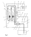
- Fig. 1 illustrates a fuel dispensing unit 1 that incorporates the system and which is divided into a first subspace 2 and a second subspace 3. Both subspaces 2, 3 are indicated by dashed lines.
- a fuel line 6 is arranged for drawing fuel from a fuel reservoir 4.
- the fuel line 6 comprises a fuel pump 5 for generating a stream of fuel, which is divided into two separates streams each entering a respective fuel meter 7, 8.
- the first fuel meter 7 is downstream connected to a first fuel line 9 to which a first, flexible fuel hose 10 is connected.
- the first fuel hose 10 has a fuel dispensing nozzle 11 for dispensing fuel into a tank of a vehicle (not shown).
- the second fuel meter 8 is downstream connected to a second fuel line 13 to which a second, flexible fuel hose 14 is connected, which in turn has a fuel dispensing nozzle 15 corresponding the nozzle 11 of the first fuel hose 10.
- a second, flexible fuel hose 14 which in turn has a fuel dispensing nozzle 15 corresponding the nozzle 11 of the first fuel hose 10.
- each fuel meter 7, 8 has a unique identifier corresponding to the identifiers of the switches described blow.
- the communication line 18 comprises an EExi barrier device 23 which is arranged between the control unit 19 and fuel meters 7, 8 in order to provide explosion protection for flammable fuel present in, for example, the fuel meters 7, 8.
- the EExi barrier device 23 is preferably an electronic device having a protective function in potentially explosive atmospheres, and its technical requirements are stipulated in Directive 94/9/EC (ATEX).
- the EExi barrier device 23 may also be a barrier device according to CENELEC standards, or according to any other suitable standard for providing the required protection.
- an EExd, EExp, EExn or EExm barrier device may be used, or any other device providing similar functionality.
- the barrier device 23 is intrinsically safe by ensuring that electric current and voltage levels are reduced in the electric components that are arranged in the second subspace 3, were fuel vapour is more common.
- the first subspace 2 is sealed from the second subspace 3 by means of a boxlike structure (not shown) made of steel or plastic and encloses the control unit 19 and thereby prevents fuel vapour from spreading from the second subspace 3 to the first subspace 2.
- a sealing member 22 is arranged between the first subspace 2 and the second subspace 3.
- the sealing member 22 comprises two flexible members that abut closely against the communication line 18 and thereby provide a vapour tight cable penetration between the subspaces 2, 3.
- Two switches 25, 26 are arranged in the second subspace 3 for detecting events indicative of misuse of the fuel dispensing unit 1.
- the switches 25, 26 detect in a conventional manner, for example, opening of a front panel (not shown), vibrations and impacts on the fuel dispensing unit, a sound having a frequency corresponding to a frequency generated when drilling through a front panel of the fuel dispensing unit 1, or any other event indicative of misuse of the fuel dispensing unit 1.
- the communication line 18 may, of course, have multiple wires, but signals from both switches 25, 26 are still sent to the control unit 19 via a common wire of the multiple wires.
- a first nozzle detecting switch 27 is arranged at the first nozzle boot 12, while a second nozzle detecting switch 28 is arranged at the second nozzle boot 16.
- Each nozzle detecting switch 27, 28 has a magnetic sensor that detects a magnetic field generated by a magnet (not shown) arranged in the respective fuel dispensing nozzle 11, 15, when respective fuel dispensing nozzle 11, 15 is properly placed in its nozzle boot 12, 16.
- Both nozzle detecting switches 27, 28 are connected to the control unit 19, via the communication line 18 which is common also for the two switches 27, 28, in a manner that corresponds to the connection of the previously discussed tamper-detecting switches 25, 26.
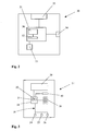
- the switches 25, 26, 27, 28 discussed above are illustrated by the generic switch 30 illustrated in Fig. 2 .
- the switch 30 has a conventional, suitable microcontroller 31 which comprises a central processing unit 36, a combined RAM and ROM memory unit 32, input/output interfaces and a clock generator (not shown).
- the switch 30 comprises also a battery 33 and a connector 34, which both are connected to the microcontroller 31.
- the connector 34 is arranged for connecting the switch 30 to the communication line 18.
- the switch 30 also incorporates a sensor 35 which communicates with the microcontroller 31. Depending on the field of application for the switch 30, the sensor 35 is configured to detect a specific sound, a magnetic field, vibrations etc.
- the components of the switch 30 cooperates in a conventional manner, and the earlier described switches 25, 26, 27, 28 are, except for the sensor 35 that depends on the particular application area for each switch 25, 26, 27, 28, structurally identical with the switch 30 of Fig. 2 .
- each switch 25, 26, 27, 28 has a unique identifier
- each unique identifier is stored in the memory 32 of each switch 25, 26, 27, 28 .
- each signal to and from the switches 25, 26, 27, 28 incorporates such a unique identifier
- each switch 25, 26, 27, 28 is in a conventional manner arranged to respond only to signals involving its unique identifier.
- signals from the switches 25, 26, 27, 28 incorporate its unique identifier, which enables the control unit 19 to, in a conventional manner, identify from which switch 25, 26, 27, 28 the signal is sent.
- a "signal" means a data package or signal package.
- data is carried in bit-serial form, and any suitable serial bus specification may be employed for the connection and communication between the control unit 19 and the switches 25, 26, 27, 28, such as, for example, the CAN-specification.
- Each of the tamper-detecting switches 25, 26 has a key stored in its memory 32, which key is also stored in the control unit 19.
- the control unit 19 repeatedly, e.g. once every 30 seconds, interrogates each tamper-detecting switch 25, 26 for its key, and as long as a correct key is received, operation of the fuel dispensing unit 1 is allowed. However, when a tamper-detecting switch 25, 26 indicates detection of the event that it is configured to detect, the key is deleted from its memory 22, preferably by the switch itself. This means that the control unit 19 will not longer receive a correct key, which is interpreted by the control unit 19 as misuse of the fuel dispensing unit 1 and which triggers a suitable alarm, such as warning signal in a manned petrol station. If the connection between a tamper-detecting switch 25, 26 and the control unit 19 is lost, the control unit 19 receives no answer at all from the switch 25, 26, which also triggers the alarm.
- control unit 19 After a tamper-detecting switch 25, 26 is released and should be reset by maintenance personnel, the control unit 19 sends a new key to the released switch 25, 26.
- Fig. 3 illustrates a fuel payment terminal 37 that incorporates the system.
- the fuel payment terminal 37 has a control unit 19 corresponding to the control unit of the fuel dispenser and to which a display 38, a keyboard 39 and a credit/payment card unit 40 is connected.
- the control unit 19 has a processor 20 and a memory 21, and three tamper detecting switches 24, 25, 26 are connected to the control unit 19 via one, common communication line 18.
- the switches 24, 25, 26 are configured, detect misuse and cooperate with the control unit 19 via the communication line 18 in a manner corresponding to the control unit, communication line and tamper detecting switches of the fuel dispensing unit described above.
Landscapes
- Engineering & Computer Science (AREA)
- Mechanical Engineering (AREA)
- Loading And Unloading Of Fuel Tanks Or Ships (AREA)
Claims (18)
- System zum Gewährleisten der Abgabe von Kraftstoff zum Auftanken von Fahrzeugen, das eine Steuereinheit (19) und wenigstens zwei Schalter (25, 26, 27, 28) umfasst,
dadurch gekennzeichnet, dass jeder der Schalter (25, 26, 27, 28) mit der Steuereinheit (19) verbunden ist und einen Mikrocontroller (31) zum Speichern einer eindeutigen Kennung umfasst, wobei die Kennung mit dem Schalter (25, 26, 27, 28) verknüpft und durch die Steuereinheit (19) lesbar ist, um zu ermöglichen, dass die Steuereinheit (19) jeden der wenigstens zwei Schalter (25, 26, 27, 28) identifiziert. - System nach Anspruch 1, wobei jeder Schalter (25, 26) eine Energiequelle (33) umfasst.
- System nach Anspruch 1 oder 2, wobei jeder Schalter (25, 26) dafür konfiguriert ist, einen Schlüssel zu speichern, der einen Zustand darstellt, in dem ein unbefugter Eingriff an der Kraftstoffabgabe-Einheit unerkannt ist.
- System nach Anspruch 3, wobei der Schlüssel verändert wird, wenn der Schalter (25, 26) freigegeben wird.
- System nach Anspruch 3 oder 4, wobei der Schlüssel verändert wird, wenn die Verbindung zwischen dem Schalter (25, 26) und der Steuereinheit (19) unterbrochen ist.
- System nach einem der Ansprüche 3 bis 5, wobei die Steuereinheit (19) dafür konfiguriert ist, eine Kopie jedes Schlüssels zu speichern, zum Zweck des Überprüfens, ob ein unbefugter Eingriff an der Kraftstoffabgabe-Einheit aufgetreten ist.
- System nach einem der Ansprüche 3 bis 6, wobei die Steuereinheit (19) dafür konfiguriert ist, regelmäßig den Schlüssel für jeden Schalter (25, 26) auszulesen.
- System nach einem der Ansprüche 3 bis 7, wobei die Steuereinheit (19) dafür konfiguriert ist, regelmäßig den Schlüssel für jeden Schalter (25, 26) zu verändern.
- System nach einem der Ansprüche 1 bis 8, wobei jeder der wenigstens zwei Schalter (25, 26, 27, 28) über eine gemeinsame Verbindungsleitung (18) mit der Steuereinheit (19) verbunden ist.
- Kraftstoffabgabe-Einheit (1) zum Auftanken von Fahrzeugen, die ein System nach einem der Ansprüche 1 bis 9 umfasst.
- Kraftstoffabgabe-Einheit nach Anspruch 10, wobei die Steuereinheit (19) in einem ersten Unterraum (2) der Kraftstoffabgabe-Einheit angeordnet ist und jeder der wenigstens zwei Schalter (25, 26, 27, 28) in einem zweiten Unterraum (3) der Kraftstoffabgabe-Einheit angeordnet ist.
- Kraftstoffabgabe-Einheit nach Anspruch 11, wobei der erste Unterraum (2) und der zweite Unterraum (3) dafür angeordnet sind, zu verhindern, dass sich Kraftstoffdampf zwischen den Unterräumen (2, 3) ausbreitet.
- Kraftstoffabgabe-Einheit nach einem der Ansprüche 10 bis 12, wobei jeder der Schalter (25, 26, 27, 28) über eine Sperreinrichtung (23) zum Explosionsschutz mit der Steuereinheit (19) verbunden ist, wobei die Sperreinrichtung (23) zwischen den Schaltern (25, 26, 27, 28) und der Steuereinheit (19) angeordnet ist.
- Kraftstoffabgabe-Einheit nach einem der Ansprüche 10 bis 13, wobei ein Abdichtungselement (22) zwischen dem ersten Unterraum (2) und dem zweiten Unterraum (3) angeordnet ist, für ein enges Anstoßen an eine Verbindungsleitung (18), die jeden der wenigstens zwei Schalter (25, 26, 27, 28) mit der Steuereinheit (19) verbindet.
- Kraftstoffabgabe-Einheit nach Anspruch 14, wobei ein Kraftstoff-Durchflussmessgerät (7, 8) mit der Verbindungsleitung (18) verbunden ist.
- Kraftstoffabgabe-Einheit nach Anspruch 15, wobei jeder der Schalter (25, 26, 27, 28) über das Durchflussmessgerät (7, 8) mit der Steuereinheit (19) verbunden ist.
- Kraftstoffabgabe-Einheit nach einem der Ansprüche 10 bis 16, wobei die Schalter (27, 28) dafür angeordnet sind, eine jeweilige Kraftstoff-Abgabedüse (11, 15) zu erkennen.
- Kraftstoff-Bezahlterminal (37), das ein System nach einem der Ansprüche 1 bis 9 umfasst.
Priority Applications (4)
| Application Number | Priority Date | Filing Date | Title |
|---|---|---|---|
| DK07108732.4T DK1995210T3 (da) | 2007-05-23 | 2007-05-23 | Brændstofdispenser med intelligent omskifter |
| ES07108732T ES2401193T3 (es) | 2007-05-23 | 2007-05-23 | Dispensador de combustible con conmutador inteligente |
| EP07108732A EP1995210B1 (de) | 2007-05-23 | 2007-05-23 | Kraftstoffabgabevorrichtung mit intelligentem Schalter |
| US12/124,928 US8123116B2 (en) | 2007-05-23 | 2008-05-21 | Fuel dispenser with intelligent switch |
Applications Claiming Priority (1)
| Application Number | Priority Date | Filing Date | Title |
|---|---|---|---|
| EP07108732A EP1995210B1 (de) | 2007-05-23 | 2007-05-23 | Kraftstoffabgabevorrichtung mit intelligentem Schalter |
Publications (2)
| Publication Number | Publication Date |
|---|---|
| EP1995210A1 EP1995210A1 (de) | 2008-11-26 |
| EP1995210B1 true EP1995210B1 (de) | 2012-12-12 |
Family
ID=38537787
Family Applications (1)
| Application Number | Title | Priority Date | Filing Date |
|---|---|---|---|
| EP07108732A Not-in-force EP1995210B1 (de) | 2007-05-23 | 2007-05-23 | Kraftstoffabgabevorrichtung mit intelligentem Schalter |
Country Status (4)
| Country | Link |
|---|---|
| US (1) | US8123116B2 (de) |
| EP (1) | EP1995210B1 (de) |
| DK (1) | DK1995210T3 (de) |
| ES (1) | ES2401193T3 (de) |
Families Citing this family (13)
| Publication number | Priority date | Publication date | Assignee | Title |
|---|---|---|---|---|
| US20080128453A1 (en) * | 2006-11-30 | 2008-06-05 | Flint Loc Security Llc | Dispenser security system |
| US8285506B2 (en) * | 2010-02-02 | 2012-10-09 | Gilbarco Inc. | Fuel dispenser pulser arrangement |
| US20110199225A1 (en) * | 2010-02-15 | 2011-08-18 | Honeywell International Inc. | Use of token switch to indicate unauthorized manipulation of a protected device |
| FR2958925B1 (fr) * | 2010-04-19 | 2012-05-25 | Tokheim Holding Bv | Distributeur de carburant equipe d'un dispositif formant barriere de protection anti-explosion ainsi que procede de montage d'un tel distributeur de carburant |
| US8757009B2 (en) | 2010-12-08 | 2014-06-24 | Danaher Uk Industries Limited | Fuel dispenser flow meter sensor fraud prevention |
| WO2012145681A1 (en) | 2011-04-20 | 2012-10-26 | Gilbarco, Inc. | Fuel dispenser flow meter fraud detection and prevention |
| US10040680B2 (en) | 2012-05-03 | 2018-08-07 | Daniel McNicholas | Compressed natural gas vehicle safety system and method |
| US8662235B2 (en) | 2012-05-03 | 2014-03-04 | Daniel McNicholas | Compressed natural gas vehicle safety system and method |
| MX2015012073A (es) | 2013-03-15 | 2016-06-10 | Gilbarco Inc | Deteccion y prevencion de fraude en el medidor de flujo de dispensadores de combustible. |
| EP2778115A1 (de) * | 2013-03-15 | 2014-09-17 | Dresser Wayne AB | Brennstoffabgabeeinheit zur Betankung eines Fahrzeugs |
| US20150148942A1 (en) * | 2013-11-24 | 2015-05-28 | C. Owen DeWitt | Control Board and Dispenser Security Monitoring System |
| IL279973B2 (en) * | 2021-01-06 | 2024-08-01 | Orpak Systems Ltd | Device for automated fuel delivery and authorization |
| ES3046410T3 (en) | 2021-05-03 | 2025-12-02 | Dover Fueling Solutions Uk Ltd | Fuel dispenser with an rfid identifiable fuel nozzle |
Family Cites Families (5)
| Publication number | Priority date | Publication date | Assignee | Title |
|---|---|---|---|---|
| US5270943A (en) * | 1992-01-03 | 1993-12-14 | Progressive International Electronics | Fuel pump control card |
| US5602745A (en) * | 1995-01-18 | 1997-02-11 | Gilbarco Inc. | Fuel dispenser electronics design |
| US6067476A (en) | 1997-10-30 | 2000-05-23 | Gilbarco Inc. | Apparatus and method to detect tampering with fuel dispenser totalizer |
| US6082618A (en) * | 1998-07-08 | 2000-07-04 | Dresser Industries, Inc. | Fuel dispenser hardware identification system |
| US6882941B2 (en) * | 2002-11-06 | 2005-04-19 | Gilbraco Inc. | Tamper proof meter |
-
2007
- 2007-05-23 ES ES07108732T patent/ES2401193T3/es active Active
- 2007-05-23 DK DK07108732.4T patent/DK1995210T3/da active
- 2007-05-23 EP EP07108732A patent/EP1995210B1/de not_active Not-in-force
-
2008
- 2008-05-21 US US12/124,928 patent/US8123116B2/en active Active
Also Published As
| Publication number | Publication date |
|---|---|
| ES2401193T3 (es) | 2013-04-17 |
| US8123116B2 (en) | 2012-02-28 |
| DK1995210T3 (da) | 2013-03-18 |
| US20080290152A1 (en) | 2008-11-27 |
| EP1995210A1 (de) | 2008-11-26 |
Similar Documents
| Publication | Publication Date | Title |
|---|---|---|
| EP1995210B1 (de) | Kraftstoffabgabevorrichtung mit intelligentem Schalter | |
| US11008210B2 (en) | Fuel dispenser with fraud detecting breakaway valve assembly | |
| US20160042617A1 (en) | Fuel Dispenser Input Device Tamper Detection Arrangement | |
| US20080128453A1 (en) | Dispenser security system | |
| US8874937B2 (en) | Fuel dispenser user interface | |
| CN103703494B (zh) | 加油机输入设备篡改检测装置 | |
| US20220153569A1 (en) | Fuel dispenser with fraud resistant flow control valve | |
| WO2016019295A1 (en) | Fuel dispenser anti-skimming input device | |
| WO1998045820A1 (en) | Service station island transaction terminal | |
| US20150148942A1 (en) | Control Board and Dispenser Security Monitoring System | |
| US8395523B2 (en) | Method and system for preventing fuel theft | |
| US10605653B1 (en) | Ambient light detector dispenser security monitoring system | |
| JPH072058A (ja) | 反不正変更保護付き電子識別システム | |
| EP1554703B1 (de) | Drahtlose sicherheitsbake für verbrauchergeräte | |
| JP4149275B2 (ja) | 給油所の水検知システム | |
| WO2020039174A1 (en) | Tamper detection system | |
| EP1666406B1 (de) | Diebstahlschutzvorrichtung | |
| WO2017103829A1 (en) | A safe apparatus for discouraging theft of banknotes | |
| WO2018069940A2 (en) | Fuel dispenser with hose damage avoidance arrangement | |
| EP4086222A1 (de) | Kraftstoffzapfanlage mit mittels rfid identifizierbarer zapfpistole | |
| CN102289872A (zh) | 磁条读取设备及其读取口保护装置及方法 | |
| GB2435036A (en) | Incorrect fuel warning system | |
| US20250276888A1 (en) | Gas hose pull away alarm system | |
| KR101265337B1 (ko) | 건설기계의 도난방지장치 및 그의 동작방법 | |
| JP2676926B2 (ja) | 燃料遮断制御装置 |
Legal Events
| Date | Code | Title | Description |
|---|---|---|---|
| PUAI | Public reference made under article 153(3) epc to a published international application that has entered the european phase |
Free format text: ORIGINAL CODE: 0009012 |
|
| AK | Designated contracting states |
Kind code of ref document: A1 Designated state(s): AT BE BG CH CY CZ DE DK EE ES FI FR GB GR HU IE IS IT LI LT LU LV MC MT NL PL PT RO SE SI SK TR |
|
| AX | Request for extension of the european patent |
Extension state: AL BA HR MK RS |
|
| 17P | Request for examination filed |
Effective date: 20090526 |
|
| AKX | Designation fees paid |
Designated state(s): AT BE BG CH CY CZ DE DK EE ES FI FR GB GR HU IE IS IT LI LT LU LV MC MT NL PL PT RO SE SI SK TR |
|
| RAP1 | Party data changed (applicant data changed or rights of an application transferred) |
Owner name: DRESSER WAYNE AB |
|
| REG | Reference to a national code |
Ref country code: DE Ref legal event code: R079 Ref document number: 602007027271 Country of ref document: DE Free format text: PREVIOUS MAIN CLASS: B67D0005320000 Ipc: B67D0007320000 |
|
| GRAP | Despatch of communication of intention to grant a patent |
Free format text: ORIGINAL CODE: EPIDOSNIGR1 |
|
| RIC1 | Information provided on ipc code assigned before grant |
Ipc: B67D 7/32 20100101AFI20120607BHEP Ipc: B67D 7/34 20100101ALI20120607BHEP |
|
| GRAS | Grant fee paid |
Free format text: ORIGINAL CODE: EPIDOSNIGR3 |
|
| GRAA | (expected) grant |
Free format text: ORIGINAL CODE: 0009210 |
|
| AK | Designated contracting states |
Kind code of ref document: B1 Designated state(s): AT BE BG CH CY CZ DE DK EE ES FI FR GB GR HU IE IS IT LI LT LU LV MC MT NL PL PT RO SE SI SK TR |
|
| REG | Reference to a national code |
Ref country code: GB Ref legal event code: FG4D |
|
| REG | Reference to a national code |
Ref country code: CH Ref legal event code: EP |
|
| REG | Reference to a national code |
Ref country code: AT Ref legal event code: REF Ref document number: 588241 Country of ref document: AT Kind code of ref document: T Effective date: 20121215 |
|
| REG | Reference to a national code |
Ref country code: IE Ref legal event code: FG4D |
|
| REG | Reference to a national code |
Ref country code: DE Ref legal event code: R096 Ref document number: 602007027271 Country of ref document: DE Effective date: 20130131 |
|
| REG | Reference to a national code |
Ref country code: CH Ref legal event code: NV Representative=s name: FIAMMENGHI-FIAMMENGHI, CH |
|
| REG | Reference to a national code |
Ref country code: DK Ref legal event code: T3 |
|
| REG | Reference to a national code |
Ref country code: SE Ref legal event code: TRGR |
|
| REG | Reference to a national code |
Ref country code: ES Ref legal event code: FG2A Ref document number: 2401193 Country of ref document: ES Kind code of ref document: T3 Effective date: 20130417 |
|
| PG25 | Lapsed in a contracting state [announced via postgrant information from national office to epo] |
Ref country code: LT Free format text: LAPSE BECAUSE OF FAILURE TO SUBMIT A TRANSLATION OF THE DESCRIPTION OR TO PAY THE FEE WITHIN THE PRESCRIBED TIME-LIMIT Effective date: 20121212 |
|
| REG | Reference to a national code |
Ref country code: NL Ref legal event code: VDEP Effective date: 20121212 |
|
| REG | Reference to a national code |
Ref country code: AT Ref legal event code: MK05 Ref document number: 588241 Country of ref document: AT Kind code of ref document: T Effective date: 20121212 |
|
| REG | Reference to a national code |
Ref country code: LT Ref legal event code: MG4D |
|
| PG25 | Lapsed in a contracting state [announced via postgrant information from national office to epo] |
Ref country code: LV Free format text: LAPSE BECAUSE OF FAILURE TO SUBMIT A TRANSLATION OF THE DESCRIPTION OR TO PAY THE FEE WITHIN THE PRESCRIBED TIME-LIMIT Effective date: 20121212 Ref country code: SI Free format text: LAPSE BECAUSE OF FAILURE TO SUBMIT A TRANSLATION OF THE DESCRIPTION OR TO PAY THE FEE WITHIN THE PRESCRIBED TIME-LIMIT Effective date: 20121212 Ref country code: GR Free format text: LAPSE BECAUSE OF FAILURE TO SUBMIT A TRANSLATION OF THE DESCRIPTION OR TO PAY THE FEE WITHIN THE PRESCRIBED TIME-LIMIT Effective date: 20130313 |
|
| PG25 | Lapsed in a contracting state [announced via postgrant information from national office to epo] |
Ref country code: AT Free format text: LAPSE BECAUSE OF FAILURE TO SUBMIT A TRANSLATION OF THE DESCRIPTION OR TO PAY THE FEE WITHIN THE PRESCRIBED TIME-LIMIT Effective date: 20121212 Ref country code: IS Free format text: LAPSE BECAUSE OF FAILURE TO SUBMIT A TRANSLATION OF THE DESCRIPTION OR TO PAY THE FEE WITHIN THE PRESCRIBED TIME-LIMIT Effective date: 20130412 Ref country code: BG Free format text: LAPSE BECAUSE OF FAILURE TO SUBMIT A TRANSLATION OF THE DESCRIPTION OR TO PAY THE FEE WITHIN THE PRESCRIBED TIME-LIMIT Effective date: 20130312 Ref country code: CY Free format text: LAPSE BECAUSE OF FAILURE TO SUBMIT A TRANSLATION OF THE DESCRIPTION OR TO PAY THE FEE WITHIN THE PRESCRIBED TIME-LIMIT Effective date: 20121212 Ref country code: SK Free format text: LAPSE BECAUSE OF FAILURE TO SUBMIT A TRANSLATION OF THE DESCRIPTION OR TO PAY THE FEE WITHIN THE PRESCRIBED TIME-LIMIT Effective date: 20121212 Ref country code: EE Free format text: LAPSE BECAUSE OF FAILURE TO SUBMIT A TRANSLATION OF THE DESCRIPTION OR TO PAY THE FEE WITHIN THE PRESCRIBED TIME-LIMIT Effective date: 20121212 Ref country code: BE Free format text: LAPSE BECAUSE OF FAILURE TO SUBMIT A TRANSLATION OF THE DESCRIPTION OR TO PAY THE FEE WITHIN THE PRESCRIBED TIME-LIMIT Effective date: 20121212 |
|
| PG25 | Lapsed in a contracting state [announced via postgrant information from national office to epo] |
Ref country code: PL Free format text: LAPSE BECAUSE OF FAILURE TO SUBMIT A TRANSLATION OF THE DESCRIPTION OR TO PAY THE FEE WITHIN THE PRESCRIBED TIME-LIMIT Effective date: 20121212 Ref country code: PT Free format text: LAPSE BECAUSE OF FAILURE TO SUBMIT A TRANSLATION OF THE DESCRIPTION OR TO PAY THE FEE WITHIN THE PRESCRIBED TIME-LIMIT Effective date: 20130412 Ref country code: RO Free format text: LAPSE BECAUSE OF FAILURE TO SUBMIT A TRANSLATION OF THE DESCRIPTION OR TO PAY THE FEE WITHIN THE PRESCRIBED TIME-LIMIT Effective date: 20121212 Ref country code: NL Free format text: LAPSE BECAUSE OF FAILURE TO SUBMIT A TRANSLATION OF THE DESCRIPTION OR TO PAY THE FEE WITHIN THE PRESCRIBED TIME-LIMIT Effective date: 20121212 |
|
| PLBE | No opposition filed within time limit |
Free format text: ORIGINAL CODE: 0009261 |
|
| STAA | Information on the status of an ep patent application or granted ep patent |
Free format text: STATUS: NO OPPOSITION FILED WITHIN TIME LIMIT |
|
| 26N | No opposition filed |
Effective date: 20130913 |
|
| PG25 | Lapsed in a contracting state [announced via postgrant information from national office to epo] |
Ref country code: MC Free format text: LAPSE BECAUSE OF FAILURE TO SUBMIT A TRANSLATION OF THE DESCRIPTION OR TO PAY THE FEE WITHIN THE PRESCRIBED TIME-LIMIT Effective date: 20121212 |
|
| REG | Reference to a national code |
Ref country code: DE Ref legal event code: R097 Ref document number: 602007027271 Country of ref document: DE Effective date: 20130913 |
|
| REG | Reference to a national code |
Ref country code: IE Ref legal event code: MM4A |
|
| PG25 | Lapsed in a contracting state [announced via postgrant information from national office to epo] |
Ref country code: IE Free format text: LAPSE BECAUSE OF NON-PAYMENT OF DUE FEES Effective date: 20130523 |
|
| PGFP | Annual fee paid to national office [announced via postgrant information from national office to epo] |
Ref country code: GB Payment date: 20140527 Year of fee payment: 8 |
|
| PGFP | Annual fee paid to national office [announced via postgrant information from national office to epo] |
Ref country code: ES Payment date: 20140526 Year of fee payment: 8 Ref country code: CH Payment date: 20140527 Year of fee payment: 8 Ref country code: IT Payment date: 20140523 Year of fee payment: 8 Ref country code: FR Payment date: 20140519 Year of fee payment: 8 Ref country code: FI Payment date: 20140529 Year of fee payment: 8 Ref country code: DE Payment date: 20140529 Year of fee payment: 8 |
|
| PGFP | Annual fee paid to national office [announced via postgrant information from national office to epo] |
Ref country code: DK Payment date: 20140602 Year of fee payment: 8 |
|
| PG25 | Lapsed in a contracting state [announced via postgrant information from national office to epo] |
Ref country code: MT Free format text: LAPSE BECAUSE OF FAILURE TO SUBMIT A TRANSLATION OF THE DESCRIPTION OR TO PAY THE FEE WITHIN THE PRESCRIBED TIME-LIMIT Effective date: 20121212 |
|
| PG25 | Lapsed in a contracting state [announced via postgrant information from national office to epo] |
Ref country code: TR Free format text: LAPSE BECAUSE OF FAILURE TO SUBMIT A TRANSLATION OF THE DESCRIPTION OR TO PAY THE FEE WITHIN THE PRESCRIBED TIME-LIMIT Effective date: 20121212 |
|
| PG25 | Lapsed in a contracting state [announced via postgrant information from national office to epo] |
Ref country code: LU Free format text: LAPSE BECAUSE OF NON-PAYMENT OF DUE FEES Effective date: 20130523 Ref country code: HU Free format text: LAPSE BECAUSE OF FAILURE TO SUBMIT A TRANSLATION OF THE DESCRIPTION OR TO PAY THE FEE WITHIN THE PRESCRIBED TIME-LIMIT; INVALID AB INITIO Effective date: 20070523 |
|
| REG | Reference to a national code |
Ref country code: DE Ref legal event code: R119 Ref document number: 602007027271 Country of ref document: DE |
|
| REG | Reference to a national code |
Ref country code: DK Ref legal event code: EBP Effective date: 20150531 |
|
| REG | Reference to a national code |
Ref country code: CH Ref legal event code: PL |
|
| GBPC | Gb: european patent ceased through non-payment of renewal fee |
Effective date: 20150523 |
|
| PG25 | Lapsed in a contracting state [announced via postgrant information from national office to epo] |
Ref country code: IT Free format text: LAPSE BECAUSE OF NON-PAYMENT OF DUE FEES Effective date: 20150523 Ref country code: FI Free format text: LAPSE BECAUSE OF NON-PAYMENT OF DUE FEES Effective date: 20150523 Ref country code: CH Free format text: LAPSE BECAUSE OF NON-PAYMENT OF DUE FEES Effective date: 20150531 Ref country code: LI Free format text: LAPSE BECAUSE OF NON-PAYMENT OF DUE FEES Effective date: 20150531 |
|
| REG | Reference to a national code |
Ref country code: FR Ref legal event code: ST Effective date: 20160129 |
|
| PG25 | Lapsed in a contracting state [announced via postgrant information from national office to epo] |
Ref country code: CZ Free format text: LAPSE BECAUSE OF NON-PAYMENT OF DUE FEES Effective date: 20150523 Ref country code: SE Free format text: LAPSE BECAUSE OF NON-PAYMENT OF DUE FEES Effective date: 20150524 |
|
| PG25 | Lapsed in a contracting state [announced via postgrant information from national office to epo] |
Ref country code: DK Free format text: LAPSE BECAUSE OF NON-PAYMENT OF DUE FEES Effective date: 20150531 Ref country code: DE Free format text: LAPSE BECAUSE OF NON-PAYMENT OF DUE FEES Effective date: 20151201 Ref country code: GB Free format text: LAPSE BECAUSE OF NON-PAYMENT OF DUE FEES Effective date: 20150523 |
|
| PG25 | Lapsed in a contracting state [announced via postgrant information from national office to epo] |
Ref country code: FR Free format text: LAPSE BECAUSE OF NON-PAYMENT OF DUE FEES Effective date: 20150601 |
|
| REG | Reference to a national code |
Ref country code: ES Ref legal event code: FD2A Effective date: 20161128 |
|
| PG25 | Lapsed in a contracting state [announced via postgrant information from national office to epo] |
Ref country code: ES Free format text: LAPSE BECAUSE OF NON-PAYMENT OF DUE FEES Effective date: 20150524 |
|
| PGFP | Annual fee paid to national office [announced via postgrant information from national office to epo] |
Ref country code: SE Payment date: 20180627 Year of fee payment: 12 |