EP1995172B1 - Plasma actuator system and method for use with a weapons bay on a high speed mobile platform - Google Patents
Plasma actuator system and method for use with a weapons bay on a high speed mobile platform Download PDFInfo
- Publication number
- EP1995172B1 EP1995172B1 EP08156378A EP08156378A EP1995172B1 EP 1995172 B1 EP1995172 B1 EP 1995172B1 EP 08156378 A EP08156378 A EP 08156378A EP 08156378 A EP08156378 A EP 08156378A EP 1995172 B1 EP1995172 B1 EP 1995172B1
- Authority
- EP
- European Patent Office
- Prior art keywords
- electrodes
- plasma actuator
- pair
- cavity
- mobile platform
- Prior art date
- Legal status (The legal status is an assumption and is not a legal conclusion. Google has not performed a legal analysis and makes no representation as to the accuracy of the status listed.)
- Active
Links
- 238000000034 method Methods 0.000 title claims description 11
- 238000000926 separation method Methods 0.000 claims description 22
- 238000011144 upstream manufacturing Methods 0.000 claims description 18
- 239000003989 dielectric material Substances 0.000 claims description 15
- 230000009977 dual effect Effects 0.000 description 9
- 230000005684 electric field Effects 0.000 description 6
- 230000008859 change Effects 0.000 description 4
- 239000012530 fluid Substances 0.000 description 4
- 230000001965 increasing effect Effects 0.000 description 4
- 230000005534 acoustic noise Effects 0.000 description 3
- 238000012986 modification Methods 0.000 description 3
- 230000004048 modification Effects 0.000 description 3
- 230000003466 anti-cipated effect Effects 0.000 description 2
- 238000013459 approach Methods 0.000 description 2
- 238000013461 design Methods 0.000 description 2
- 239000012636 effector Substances 0.000 description 2
- 230000000694 effects Effects 0.000 description 2
- 239000011888 foil Substances 0.000 description 2
- 230000001939 inductive effect Effects 0.000 description 2
- BCCGKQFZUUQSEX-WBPXWQEISA-N (2r,3r)-2,3-dihydroxybutanedioic acid;3,4-dimethyl-2-phenylmorpholine Chemical compound OC(=O)[C@H](O)[C@@H](O)C(O)=O.OC(=O)[C@H](O)[C@@H](O)C(O)=O.O1CCN(C)C(C)C1C1=CC=CC=C1 BCCGKQFZUUQSEX-WBPXWQEISA-N 0.000 description 1
- RZVHIXYEVGDQDX-UHFFFAOYSA-N 9,10-anthraquinone Chemical compound C1=CC=C2C(=O)C3=CC=CC=C3C(=O)C2=C1 RZVHIXYEVGDQDX-UHFFFAOYSA-N 0.000 description 1
- RYGMFSIKBFXOCR-UHFFFAOYSA-N Copper Chemical compound [Cu] RYGMFSIKBFXOCR-UHFFFAOYSA-N 0.000 description 1
- 229920006362 Teflon® Polymers 0.000 description 1
- 210000001015 abdomen Anatomy 0.000 description 1
- 230000004075 alteration Effects 0.000 description 1
- 238000007664 blowing Methods 0.000 description 1
- 230000001427 coherent effect Effects 0.000 description 1
- 238000004891 communication Methods 0.000 description 1
- 239000004020 conductor Substances 0.000 description 1
- 238000010276 construction Methods 0.000 description 1
- 229910052802 copper Inorganic materials 0.000 description 1
- 239000010949 copper Substances 0.000 description 1
- 230000007423 decrease Effects 0.000 description 1
- 230000003111 delayed effect Effects 0.000 description 1
- 230000001419 dependent effect Effects 0.000 description 1
- 230000008030 elimination Effects 0.000 description 1
- 238000003379 elimination reaction Methods 0.000 description 1
- 238000002474 experimental method Methods 0.000 description 1
- 239000000446 fuel Substances 0.000 description 1
- 238000003384 imaging method Methods 0.000 description 1
- 238000009434 installation Methods 0.000 description 1
- 239000000463 material Substances 0.000 description 1
- 238000005259 measurement Methods 0.000 description 1
- 238000000691 measurement method Methods 0.000 description 1
- 239000002245 particle Substances 0.000 description 1
- 229920003223 poly(pyromellitimide-1,4-diphenyl ether) Polymers 0.000 description 1
- 238000012797 qualification Methods 0.000 description 1
- 239000010453 quartz Substances 0.000 description 1
- 230000009467 reduction Effects 0.000 description 1
- 239000004065 semiconductor Substances 0.000 description 1
- VYPSYNLAJGMNEJ-UHFFFAOYSA-N silicon dioxide Inorganic materials O=[Si]=O VYPSYNLAJGMNEJ-UHFFFAOYSA-N 0.000 description 1
- 230000036962 time dependent Effects 0.000 description 1
- 230000032258 transport Effects 0.000 description 1
- 238000000827 velocimetry Methods 0.000 description 1
Images


Classifications
-
- B—PERFORMING OPERATIONS; TRANSPORTING
- B64—AIRCRAFT; AVIATION; COSMONAUTICS
- B64C—AEROPLANES; HELICOPTERS
- B64C21/00—Influencing air flow over aircraft surfaces by affecting boundary layer flow
-
- Y—GENERAL TAGGING OF NEW TECHNOLOGICAL DEVELOPMENTS; GENERAL TAGGING OF CROSS-SECTIONAL TECHNOLOGIES SPANNING OVER SEVERAL SECTIONS OF THE IPC; TECHNICAL SUBJECTS COVERED BY FORMER USPC CROSS-REFERENCE ART COLLECTIONS [XRACs] AND DIGESTS
- Y02—TECHNOLOGIES OR APPLICATIONS FOR MITIGATION OR ADAPTATION AGAINST CLIMATE CHANGE
- Y02T—CLIMATE CHANGE MITIGATION TECHNOLOGIES RELATED TO TRANSPORTATION
- Y02T50/00—Aeronautics or air transport
- Y02T50/10—Drag reduction
Definitions
- the present disclosure relates to plasma actuators, and more particularly to a system and method employing one or more plasma actuators for improving the acoustics of a weapons bay of a high speed mobile platform when a weapons bay door of the mobile platform is opened, and also improving the separation of a weapon being released from the weapons bay, by modifying the boundary layer flow over the weapons bay.
- airborne mobile platforms for example with jet powered military aircraft, often have various and highly integrated platform configurations.
- These configurations can include internal weapons bays, which are typically located on the belly of the fuselage of the aircraft.
- weapons bays typically located on the belly of the fuselage of the aircraft.
- a weapon stored within the weapons bay is to be released from the aircraft, typically one hingedly supported door, or a pair of hingedly supported bay doors, are opened and then the weapon is released.
- the shear layer air flow over the weapons bay can produce high acoustic levels and challenges in releasing weapons when the bay doors are opened.
- a flow spoiler is located on the fuselage of the aircraft externally of, and upstream of, the weapons bay.
- the spoiler operates to "deflect" the approaching air flow, plus “spoil” and reduce the intensity of the bay oscillating pressure waves adjacent the opening in the fuselage.
- This passive approach is usually limited in optimal performance to performing within a limited portion of the flight envelope (i.e., with a predetermined speed range for the aircraft).
- the mechanical flow spoiler typically requires mechanical linkage and electromechanical and/or hydraulic actuators, all of which can add significant weight, complexity, and life cycle costs to the air vehicle.
- Airflow control by non-thermal plasma actuators by Moreau, Eric , XP 020112117, discloses the knowledge concerning electric wind induced by surface non-thermal plasma actuators, acting in air at atmospheric pressure. This document also discloses active airflow control by plasma actuators and control of plasma actuators in association with an air foil.
- the present disclosure is related to a system and method that employs at least one plasma actuator located on a surface of a mobile platform upstream of a cavity in the mobile platform (relative to a freestream air flow over the platform) to modify a path of an airflow adjacent the cavity.
- the system may be used on any form of mobile platform in connection with any form of opening, cavity, or potentially anywhere it is desired to deflect the freestream flow moving over the mobile platform.
- the system is expected to find particularly utility in connection with military aircraft to modify a freestream air flow to reduce oscillating acoustic pressure waves within a weapons bay of the aircraft with the weapons bay door(s) is/are opened.
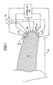
- a plasma actuator is located upstream of an upstream edge of a weapons bay on an aircraft. Energizing the plasma actuator with an electrical signal causes ionization of the air molecules in the boundary layer of a freestream air flow moving over the actuator. This also results in an electric field being developed adjacent the actuator which acts on the ionized air to create an induced flow that is directed upstream, relative to direction of the freestream air flow. This in turn causes the freestream air flow to be deflected away from the weapons bay. The deflected freestream air flow helps to significantly reduce oscillating acoustic pressure waves that would otherwise develop from a shear layer passing over and curling into the weapons bay. The reduction in the oscillating acoustic pressure waves helps to reduce acoustic levels in the weapons bay and to improve the separation characteristics for ordnance or munitions being released from the weapons bay.
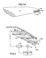
- FIG. 1 there is shown a flow control system 10 used on a wing 14 of a mobile platform 12.
- the mobile platform 12 is an aircraft, and for convenience will be referenced throughout the following discussion as "aircraft 12".
- aircraft 12 unmanned air vehicles
- the system 10 employs a plurality of plasma actuators 16 that are spaced apart along a Coanda surface 18 of the wing 14. While only four plasma actuators 16 are shown, a greater or lesser plurality could be employed to meet the needs of a specific application.
- two plasma actuators 16a, 16b are provided on a top half portion of the Coanda surface 18 while two additional plasma actuators 16c,16d are provided on a bottom half portion of the Coanda surface.
- the Coanda surface 18 need not be associated with an aircraft wing, but instead could be associated with any component, for example a rear spoiler of a land vehicle.
- top half and bottom half may instead be termed “port side half” and “starboard side half”.
- the references to “top half” and “bottom half” may instead be termed “port side half” and “starboard side half”.
- many applications may require a plurality of each of the actuators 16a, 16b, 16c and 16d to be spaced apart in a span-wise direction along the wing 14 or other form of aerodynamic surface.
- An example of this arrangement is illustrated in Figure 1A .
- the precise placement of the plasma actuators 16 may be varied as needed to meet a specific application. Fox example, arrangements of the plasma actuators 16 are also possible where the actuators are arranged with their long axes cord-wise, with many of the actuators arrayed along a wingspan to facilitate separation control with coherent vorticity.
- a controller 20 and a high voltage alternating current (AC) voltage source 22 are in communication with each plasma actuator 16.
- the controller 22 independently controls the application of a high voltage signal, preferably between about 3,000VAC up to about 20,000VAC, or possibly even higher, to each plasma actuator 16.
- Energizing any one of the plasma actuators 16 causes the actuator to ionize air in its vicinity adjacent the outer surface portion 18a of the Coanda surface 18.
- An electric field is also created that is directly proportional to the magnitude of the AC voltage being applied.
- the electric field acts on the ionized air to create an induced flow over the energized plasma actuator 16 that tends to draw the boundary layer toward the Coanda surface 18 as it moves over the Coanda surface. This helps to delay separation of the boundary layer from the Coanda surface 18.
- the plasma actuator 16a includes a first electrode 24 and a second electrode 26 separated by a dielectric material 28.
- the dielectric material 28 may form a distinct layer that is disposed between the electrodes 24 and 26, as shown in Figure 2 .
- the electrodes 24 and 26 are recess mounted in the outer surface 18a of the Coanda surface 18 so as not to interfere with its smooth surface contour.
- mounting of at least the first electrode 24 directly on the Coanda surface is also possible.
- the plasma actuators 16 are further each arranged on the Coanda surface 18 such that the second electrode 26 is positioned downstream, relative to the direction of the boundary layer flow, of the first electrode 24.
- the AC voltage source 22 is coupled between the controller 20 and the second electrode 26.
- a switch 30 is interposed between the AC voltage source 22 and the first electrode 24.
- the switch 30 may be a semiconductor switch, or it may be an electromechanical switch that is actuated by a suitable electrical signal. Essentially any form of switch may be used that meets the needs of a specific application.
- the high voltage AC signal applied across the electrodes 24 and 26 causes air in the vicinity of the electrodes 24 and 26, and closely adjacent the outer surface 18a of the Coanda surface 18, to be ionized.
- An electric field is also created between the electrodes 24 and 26.
- the electric field acts on the ionized air to induce a flow 32 closely adjacent the outer surface 18a that moves from the first electrode 24, over the outer surface 18a, and over the second electrode 26.
- the induced flow 32 serves to draw the boundary layer flow down against the outer surface 18a, which helps to delay the onset of boundary layer separation from the Coanda surface 18.
- the particulars of the construction of the electrodes 24 and 26 may vary considerably to meet the needs of a particular application.
- the electrodes 24 and 26 may be formed from any conductive material. Copper is one material that is particularly suitable.
- the electrodes 24 and 26 may be formed as thin strips, possibly as foil strips, and may have a typical thickness on the order of about 0,001-0.005inch (.0254-0.127mm).
- the length and width of each electrode 24 and 26 may vary as needed to suit specific applications, but it is anticipated that in many aircraft applications, the dimensions of each electrode may typically be on the order of 1-20 inches (2.54cm-50.08cm) for the length and 0.12-0.20inch (3-5mm) for the width.
- the dielectric material 28 may comprise any suitable dielectric material, for example quartz, KAPTON®, or TEFLON® dielectric material. Other dielectric materials may also be suitable for use, and the precise dielectric material used may be dictated by the needs of a specific application. Preferably, the dielectric material 28 provides a thickness layer of about 0.005-1.0 inch (0.127-25.4mm) between the first and second electrodes 24 and 26, respectively.
- the plasma actuators 16a and 16b are energized while actuators 16c and 16d are de-energized.
- the streamline 42 indicates that the plasma actuators 16a and 16b have delayed the onset of boundary layer separation, and streamlines 36a and 38a have been modified to be directed downwardly slightly.
- Figure 6 illustrates the flow effect with all of the plasma actuators 16 energized.
- the wake separation is reduced, thus reducing the drag on the wing 14 but without altering the pitching moment or lift.
- the system 10 provides hingeless yaw control for tailless aircraft by generating asymmetric drag.
- Asymmetric drag is created by controlling separation in the circulation control airfoil wake or inducing spanwise alteration between positive and negative circulation increments that produce increased induced drag without accompanying lift or pitching moment change.
- the system 10 enables hingeless aerodynamic control to increase aerodynamic and structural efficiency. Aerodynamic efficiency is improved by elimination of elevon edge and hingeline gaps on wings and like aerodynamic surfaces. Structural efficiency is improved by increasing torque box size which decreases weight, eliminates mechanical actuation weight and complexity, and increases wing internal volume for fuel, etc.
- the system 10 can simplify high-lift systems for aircraft (especially commercial transports with highly complex multi-element flaps) to increase low-speed performance while reducing cost, weight and complexity.
- the system 10 can potentially be used to replace trim tabs on commercial aircraft rudders or elevators, eliminating mechanical complexity of a secondary moving surface on the primary control surface.
- Use of the system 10 may produce higher control rates (high bandwidth controller) than conventional moving surface effectors since the system 10 is constrained only by the convective speed of the freestream fluid flow and not the mechanical motion of the flap effector. This enables control of more highly unstable airframes, increasing agility and performance.
- the system 10 described herein enables low-cost, reduced-complexity wing designs, which are especially useful for thin, deployable wings (missiles or small UAVs) where control surfaces are difficult to integrate using conventional approaches because of control actuation installation difficulty.
- Other applications are possible on non-flying vehicles, such as semi-trailer aero-braking assist by deactivating actuation meant to reduce trailer base drag, or traction control by inducing a downward force when a Coanda surface is installed along a trailer base perimeter.
- the system 10 is also expected to Increase mission flight time or range as a result of providing a more efficient means (structurally and aerodynamically speaking) to control an airborne mobile platform. Additional design flexibility is also enabled by new mechanizations of control devices, especially for tailless aircraft or air vehicles with deployable aero-surfaces. Increased control actuation rates may also be realized together with reduced overall complexity.
- FIG. 7 another system 100 is illustrated that makes use of a plurality of dual mode plasma actuators 102 integrated into the Coanda surface 18 of the wing 14.
- This system 100 is identical to the system 10 of Figures 1 and 1A with the exception of the use of dual mode actuators 102.
- a pair of the dual mode plasma actuators 102a and 102b is disposed on the upper half of the Coanda surface 18 of the wing 14.
- a second pair of actuators 102c and 102d is disposed on the lower half.
- a plurality of the dual mode plasma actuators 102 may be spaced apart, span-wise, along the Coanda surface 18. The precise number, spacing and arrangement of the dual mode plasma actuators 102 employed will vary to meet the needs of a specific application.
- the dual mode plasma actuators 102 are similar to the plasma actuators 16, but include three electrodes 104, 106 and 108 rather than two electrodes.
- Two switches 110 and 112 enable the AC voltage source 26 to be applied across either the first and second electrode pair 104 and 108, or between the second and third electrode pair 106 and 108.
- the third electrode 108 is separated by a suitable dielectric material layer 109, or encased in a suitable dielectric material.
- the plasma actuator 102 When the AC voltage from the AC voltage source 26 is applied across electrode pair 104 and 108 by closing switch 110 and opening switch 112, the plasma actuator 102 operates in the same manner as described for actuator 16; that is, an induced fluid flow 114 is created ( Figure 8 ).
- the direction of the induced flow 114 is the same as that of the boundary layer flow flowing over the actuator 102.
- the induced fluid flow 114 acts on the boundary layer flow to help prevent separation of the boundary layer flow from the Coanda surface 18.
- an induced flow 116 is created that is in the direction opposite to that of induced flow 114 ( Figure 9 ). In this instance the induced flow 116 helps to promote attachment of the boundary layer further around the trailing edge of the Coanda surface 18 when operated in concert with the plasma actuator on the other half of the Coanda surface.
- the system 100 provides an added degree of flow control flexibility because various ones of the plasma actuators 102 can have different pairs of electrodes 104,106,108 energized to even more significantly affect the boundary layer flow (i.e., either more significantly promote attachment or separation of the boundary layer flow).
- certain of the plasma actuators 102 for example those located on the top half of the Coanda surface 18, can be energized to create the induced flow 114 (to promote boundary layer attachment), while other ones of the actuators 102 located on the bottom half of the Coanda surface 18 can be energized to produce induced flow 116 (to enhance the turning of the flow around the Coanda surface 18).
- the overall result in this specific example is that all of the plasma actuators 102 would be working to even more significantly move the trailing edge stagnation point around the Coanda surface 18.
- the controller 20 may control the energization of specific electrode pairs 104,108 or 106,108 of the plasma actuators 102 as needed so that it produces a nose-up or nose-down moment on the surface where the system 100 is employed.
- the system 100 provides an even further enhanced range of aerodynamic flow control possibilities. It should also be appreciated that various combinations of plasma actuators 16 and 102 could be used on a surface, for example Coanda surface 18, to even further enhance control over the separation and/or attachment of the boundary layer.
- the system 200 enables the shear layer passing over a cavity of a mobile platform, for example an aircraft, to be deflected away from the cavity. This significantly reduces acoustic pressure levels within the cavity.
- the cavity is a weapons bay on an airborne mobile platform, the system also significantly improves weapons separation from the mobile platform.
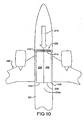
- the mobile platform is an aircraft 202 having a fuselage 204.
- a weapons bay 206 is provided at an undersurface 204a of the fuselage 204 .
- the weapons bay 206 may be covered by one or more moveable doors 208, and in this example a pair of doors 208 is shown.
- a portion immediately upstream and adjacent the weapons bay 206 is defined by reference numeral 210 and a portion immediately downstream of the weapons bay is denoted by reference numeral 212. It will be understood that the terms "upstream” and "downstream" are used in relation to the direction of a freestream air flow 216 over the fuselage 204.
- the system 200 employs at least one of the plasma actuators 16, and more preferably a plurality of the plasma actuators 16, positioned on the undersurface 204a of the fuselage 204 along the upstream portion 210.
- the plasma actuators 16 are preferably recess mounted in the fuselage 204 to maintain the smooth aerodynamic surface of the fuselage 204.
- the plasma actuators 16 in this example are arranged with their long axes generally parallel to an upstream edge 214 of the weapons bay 206. However, the plasma actuators 16 may be arranged in different orientations as dictated by the aerodynamics of a specific mobile platform or the needs of a particular application.
- the plasma actuators 16 are arranged 180 degrees from the orientation shown in Figure 2 , relative to the freestream air flow 216 passing over them. That is, they are arranged with the second electrode 26 disposed upstream of the first electrode 24. Two or more rows of the plasma actuators 16 may be incorporated, as indicated in Figure 10 .
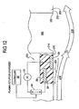
- the aircraft 202 is illustrated along with a path of a shear layer 218 that develops as the freestream air flow 216 moves over the weapons bay 206 when the bay doors 208 are opened. To avoid cluttering the Figure, the weapons bay doors 208 have not been shown in Figure 11 .
- the shear layer 218 is generally the interface between the quiescent air in the weapons bay 206 and the bulk freestream air flow 216.
- the air in the weapons bay 206 does not necessarily need to be quiescent in order for a shear layer to be generated.
- the shear layer 218 may turn into the weapons bay 206 or may impinge on the fuselage 202 downstream of an aft end 220 of the weapons bay 206. In both cases, the shear layer 218 creates oscillating acoustic pressure waves within the weapons bay 206 that in turn cause significant acoustic noise in the weapons bay.
- the oscillating waves and shear flow angularity may also interfere with separation of ordnance or guided munitions that are being released from the weapons bay 206.
- the impingement point of the shear layer 218 needs to be controlled.
- the reduced oscillating acoustic pressure waves help to improve separation of ordnance and/or guided munitions from the weapons bay 206.
- the performance of the system 200 may further be improved by controlling the duty cycle of a pulsed AC voltage signal from AC voltage source 22 to the actuators 16. Power efficiency of the system 200 may be improved as well. Controlling the duty cycle of a pulsed AC voltage signal applied to the plasma actuators 16 can enable the system 200 to function in a manner similar to previously developed active flow control (AFC) devices that typically use sucking/blowing surface mounted air jet ports. Thus, tailoring of the flow in the vicinity of the weapons bay 206 can be achieved across a larger flight envelope and, for certain weapons and ejection systems, with significantly less complexity and weight as compared to traditional spoilers or other AFC devices. This may also result in improved life cycle costs compared to what would typically be experienced with conventional mechanical spoiler and AFC systems.
- AFC active flow control
- the AC voltage output signal may be controlled to vary the amount deflection of the freestream air flow 216.
- the amount of deflection induced could also be used to control the point at which the freestream flow 216 reattaches to the fuselage 204.
- system 200 has been described as being employed to modify a separation layer adjacent a weapons bay, it will be appreciated that the system 200 is readily applicable to controlling the freestream flow adjacent any form of cavity or opening on a mobile platform. Essentially, the system 200 is potentially usable in any application where a mechanical spoiler or conventional AFC system would be desirable. While the system 200 may be especially valuable in aircraft and aerospace applications, the system 200 can be used with any mobile platform, for example a rotorcraft, unmanned air vehicle, high speed land vehicles or even high speed marine vessels. Essentially, the system 200 may have application in connection with any form of vehicle where there is a need to control the freestream flow adjacent an opening, cavity or other component on the vehicle.
Landscapes
- Engineering & Computer Science (AREA)
- Aviation & Aerospace Engineering (AREA)
- Plasma Technology (AREA)
- Physical Or Chemical Processes And Apparatus (AREA)
- Soundproofing, Sound Blocking, And Sound Damping (AREA)
Description
- The present disclosure relates to plasma actuators, and more particularly to a system and method employing one or more plasma actuators for improving the acoustics of a weapons bay of a high speed mobile platform when a weapons bay door of the mobile platform is opened, and also improving the separation of a weapon being released from the weapons bay, by modifying the boundary layer flow over the weapons bay.
- The statements in this section merely provide background information related to the present disclosure and may not constitute prior art.
- To meet many modern day performance requirements, airborne mobile platforms, for example with jet powered military aircraft, often have various and highly integrated platform configurations. These configurations can include internal weapons bays, which are typically located on the belly of the fuselage of the aircraft. When a weapon stored within the weapons bay is to be released from the aircraft, typically one hingedly supported door, or a pair of hingedly supported bay doors, are opened and then the weapon is released. However, due to the high speeds at which many jet aircraft are operating at when weapons are released from the weapons bay, the shear layer air flow over the weapons bay can produce high acoustic levels and challenges in releasing weapons when the bay doors are opened. In effect, there occurs a time-dependent separation of the shear layer at the leading edge of the weapons bay that moves in to the bay, thus producing high acoustic noise and loading. Complicating this is that existing weapons are typically qualified to maximum conditions that may not be sufficient for deployment from an internal weapons bay of an aircraft. Modification or re-qualification of the weapons is typically not an option.
- Traditionally, to passively counter the high acoustic levels experienced inside the weapons bay and to improve weapon separation characteristics, a flow spoiler is located on the fuselage of the aircraft externally of, and upstream of, the weapons bay. The spoiler operates to "deflect" the approaching air flow, plus "spoil" and reduce the intensity of the bay oscillating pressure waves adjacent the opening in the fuselage. This passive approach is usually limited in optimal performance to performing within a limited portion of the flight envelope (i.e., with a predetermined speed range for the aircraft). The mechanical flow spoiler typically requires mechanical linkage and electromechanical and/or hydraulic actuators, all of which can add significant weight, complexity, and life cycle costs to the air vehicle.
- Document "The attenuation of cavity tones using plasma actuators" by Chan, S. et al, XP 009141229, discloses a study conducted through low speed wind tunnel experiments. An array of para-electric plasma actuators were located on the approaching surface to the cavity, aligned with the direction of the oncoming flow. The fluid flow inside the cavities was studied using a range of measurement techniques. Including oil flow, particle imaging, velocimetry and surface mounted microphone measurements.
- Document "Control of high speed cavity flow using plasma actuators" by Mitchell, D.A., XP 002610057, discloses plasma actuators that are placed along a cavity leading edge and that are capable of influencing the separating shear layer. Plasma actuators were used to determine their ability in influencing the flow over the cavity, in particular the resultant pressure fluctuations.
- Document "Airflow control by non-thermal plasma actuators" by Moreau, Eric, XP 020112117, discloses the knowledge concerning electric wind induced by surface non-thermal plasma actuators, acting in air at atmospheric pressure. This document also discloses active airflow control by plasma actuators and control of plasma actuators in association with an air foil.
- The invention is set out in the independent claims. Preferred or optional features are set out in the dependent claims thereto.
- The present disclosure is related to a system and method that employs at least one plasma actuator located on a surface of a mobile platform upstream of a cavity in the mobile platform (relative to a freestream air flow over the platform) to modify a path of an airflow adjacent the cavity. The system may be used on any form of mobile platform in connection with any form of opening, cavity, or potentially anywhere it is desired to deflect the freestream flow moving over the mobile platform. The system is expected to find particularly utility in connection with military aircraft to modify a freestream air flow to reduce oscillating acoustic pressure waves within a weapons bay of the aircraft with the weapons bay door(s) is/are opened.
- In one embodiment a plasma actuator is located upstream of an upstream edge of a weapons bay on an aircraft. Energizing the plasma actuator with an electrical signal causes ionization of the air molecules in the boundary layer of a freestream air flow moving over the actuator. This also results in an electric field being developed adjacent the actuator which acts on the ionized air to create an induced flow that is directed upstream, relative to direction of the freestream air flow. This in turn causes the freestream air flow to be deflected away from the weapons bay. The deflected freestream air flow helps to significantly reduce oscillating acoustic pressure waves that would otherwise develop from a shear layer passing over and curling into the weapons bay. The reduction in the oscillating acoustic pressure waves helps to reduce acoustic levels in the weapons bay and to improve the separation characteristics for ordnance or munitions being released from the weapons bay.
- The drawings described herein are for illustration purposes only and are not intended to limit the scope of the present disclosure in any way.
-
Figure 1 is a side view of a flight control system being employed on a Coanda surface of a wing of an aircraft, where the system makes use of a plurality of plasma actuators that are positioned over the Coanda surface; -
Figure 1A shows a perspective view of a portion of the wing ofFigure 1 employing a plurality of spaced apart rows of the plasma actuators shown inFigure 1 ; -
Figure 2 is an enlarged side view of one of the plasma actuators shown inFigure 1 ; -
Figure 3 is a side view of the wing ofFigure 1 illustrating how the boundary layer flow appears with none of the plasma actuators actuated; -
Figure 4 shows the wing ofFigure 1 but with at least one of the plasma actuators on only the lower surface being energized, with the resulting change in the boundary layer flow along the Coanda surface and associated modification of circulation and streamlines about the wing section (i.e., causing the wake flow to be deflected upwardly); -
Figure 5 shows the wing ofFigure 1 but with at least one plasma actuator on only the upper surface being energized, with the resulting change in the boundary layer flow along the Coanda surface and associated modification of circulation and streamlines about the wing section (i.e., causing the wake flow to be deflected downwardly); -
Figure 6 is a view of the wing ofFigure 1 showing the boundary layer flow leaving the wing when at least one actuator on both of the upper surface and the lower surface is actuated (i.e., no significant change to the wake flow); -
Figure 7 illustrates how a plurality of dual mode plasma actuators may be employed on a Coanda surface; -
Figure 8 illustrates in greater detail one of the dual mode plasma actuators circled inFigure 7 , with its first and third electrodes connected across the AC voltage source to induce a flow that helps to delay boundary layer separation; and -
Figure 9 illustrates the dual mode plasma actuator ofFigure 8 but with the second and third electrodes connected across the AC voltage source to induce a flow that serves to promote boundary layer flow in the opposite direction; -
Figure 10 is a plan view of an undersurface of a mobile platform, in this example an aircraft, illustrating the flow control system of the present invention for use in deflecting a shear layer away from a weapons bay of the aircraft; -
Figure 11 is a side view of a portion of the fuselage of the aircraft ofFigure 10 illustrating a path of airflow over the weapons bay when the weapons bay doors are opened; and -
Figure 12 is a side view of the aircraft ofFigure 11 illustrating how the plasma actuators operate to deflect the shear layer away from the weapons bay when the bay doors are opened. - The following description is merely exemplary in nature and is not intended to limit the present disclosure, application, or uses.
- Referring to
Figure 1 , there is shown a flow control system 10 used on awing 14 of amobile platform 12. In this example themobile platform 12 is an aircraft, and for convenience will be referenced throughout the following discussion as "aircraft 12". It will be appreciated immediately, however, that the teachings of the present disclosure are not limited to use with only airborne mobile platforms employing wings, such as commercial and military aircraft, but are readily applicable to unmanned air vehicles (UAVs), missiles, rotorcraft, land vehicles and even high speed marine vessels. - In
Figure 1 the system 10 employs a plurality of plasma actuators 16 that are spaced apart along aCoanda surface 18 of thewing 14. While only four plasma actuators 16 are shown, a greater or lesser plurality could be employed to meet the needs of a specific application. In this example, twoplasma actuators Coanda surface 18 while twoadditional plasma actuators surface 18 need not be associated with an aircraft wing, but instead could be associated with any component, for example a rear spoiler of a land vehicle. If the plasma actuators are incorporated on a vertical tail of an aircraft or other form of mobile platform, then it will be appreciated that the references to "top half" and "bottom half" may instead be termed "port side half" and "starboard side half". Also, in practice, it is anticipated that many applications may require a plurality of each of theactuators wing 14 or other form of aerodynamic surface. An example of this arrangement is illustrated inFigure 1A . The precise placement of the plasma actuators 16 may be varied as needed to meet a specific application. Fox example, arrangements of the plasma actuators 16 are also possible where the actuators are arranged with their long axes cord-wise, with many of the actuators arrayed along a wingspan to facilitate separation control with coherent vorticity. - A
controller 20 and a high voltage alternating current (AC)voltage source 22 are in communication with each plasma actuator 16. Thecontroller 22 independently controls the application of a high voltage signal, preferably between about 3,000VAC up to about 20,000VAC, or possibly even higher, to each plasma actuator 16. Energizing any one of the plasma actuators 16 causes the actuator to ionize air in its vicinity adjacent theouter surface portion 18a of theCoanda surface 18. An electric field is also created that is directly proportional to the magnitude of the AC voltage being applied. The electric field acts on the ionized air to create an induced flow over the energized plasma actuator 16 that tends to draw the boundary layer toward theCoanda surface 18 as it moves over the Coanda surface. This helps to delay separation of the boundary layer from theCoanda surface 18. Referring toFigure 2 , one of theplasma actuators 16a is shown in greater detail. This form of actuator is also discussed in co-pendingU.S. application serial number 11/403,252 , filed 4/12/06, and assigned to The Boeing Company. In brief, however, theplasma actuator 16a includes afirst electrode 24 and asecond electrode 26 separated by adielectric material 28. Thedielectric material 28 may form a distinct layer that is disposed between theelectrodes Figure 2 . Preferably theelectrodes outer surface 18a of theCoanda surface 18 so as not to interfere with its smooth surface contour. However, mounting of at least thefirst electrode 24 directly on the Coanda surface is also possible. If mounted directly on theCoanda surface 18, then thefirst electrode 24 would typically not be completely encapsulated by thedielectric material 28. The plasma actuators 16 are further each arranged on theCoanda surface 18 such that thesecond electrode 26 is positioned downstream, relative to the direction of the boundary layer flow, of thefirst electrode 24. - The
AC voltage source 22 is coupled between thecontroller 20 and thesecond electrode 26. Aswitch 30 is interposed between theAC voltage source 22 and thefirst electrode 24. Theswitch 30 may be a semiconductor switch, or it may be an electromechanical switch that is actuated by a suitable electrical signal. Essentially any form of switch may be used that meets the needs of a specific application. - When the
controller 20 closes theswitch 30, the high voltage AC signal applied across theelectrodes 24 and 26 (typically at least about 3,000VAC) causes air in the vicinity of theelectrodes outer surface 18a of theCoanda surface 18, to be ionized. An electric field is also created between theelectrodes flow 32 closely adjacent theouter surface 18a that moves from thefirst electrode 24, over theouter surface 18a, and over thesecond electrode 26. The inducedflow 32 serves to draw the boundary layer flow down against theouter surface 18a, which helps to delay the onset of boundary layer separation from theCoanda surface 18. - The particulars of the construction of the
electrodes electrodes electrodes electrode dielectric material 28 may comprise any suitable dielectric material, for example quartz, KAPTON®, or TEFLON® dielectric material. Other dielectric materials may also be suitable for use, and the precise dielectric material used may be dictated by the needs of a specific application. Preferably, thedielectric material 28 provides a thickness layer of about 0.005-1.0 inch (0.127-25.4mm) between the first andsecond electrodes - Referring now to
Figures 3-6 , the influence on the boundary layer flow that is provided by selectively energizing various ones of the plasma actuators 16 will be described. Referring first toFigure 3 , the upper and lower surface streamlines 36 and 38 are shown moving over theCoanda surface 18 while none of the plasma actuators 16 (not visible) are energized. In this Figure the incremental lift coefficient induced by the system 10 ( ΔCL ) equals the incremental pitching moment coefficient induced by the system (ΔCM), and both are zero. - In
Figure 4 plasma actuators Coanda surface 18 have been energized, whileactuators arrow 40.Streamline 42 indicates howactuators Coanda surface 18. Note theportion 36a ofstreamline 36 is slightly more elevated than what appears inFigure 3 . - Referring to
Figure 5 , theplasma actuators actuators streamline 42 indicates that theplasma actuators -
Figure 6 illustrates the flow effect with all of the plasma actuators 16 energized. In this example the wake separation is reduced, thus reducing the drag on thewing 14 but without altering the pitching moment or lift. - Applications of the system 10 are numerous, including commercial and military aircraft, unmanned air vehicles (UAVs) and missiles. Benefits will also be realized on various aerodynamic surfaces of motor land vehicles such as cars and trucks.
- The system 10 provides hingeless yaw control for tailless aircraft by generating asymmetric drag. Asymmetric drag is created by controlling separation in the circulation control airfoil wake or inducing spanwise alteration between positive and negative circulation increments that produce increased induced drag without accompanying lift or pitching moment change.
- The system 10 enables hingeless aerodynamic control to increase aerodynamic and structural efficiency. Aerodynamic efficiency is improved by elimination of elevon edge and hingeline gaps on wings and like aerodynamic surfaces. Structural efficiency is improved by increasing torque box size which decreases weight, eliminates mechanical actuation weight and complexity, and increases wing internal volume for fuel, etc.
- The system 10 can simplify high-lift systems for aircraft (especially commercial transports with highly complex multi-element flaps) to increase low-speed performance while reducing cost, weight and complexity. The system 10 can potentially be used to replace trim tabs on commercial aircraft rudders or elevators, eliminating mechanical complexity of a secondary moving surface on the primary control surface. Use of the system 10 may produce higher control rates (high bandwidth controller) than conventional moving surface effectors since the system 10 is constrained only by the convective speed of the freestream fluid flow and not the mechanical motion of the flap effector. This enables control of more highly unstable airframes, increasing agility and performance. The system 10 described herein enables low-cost, reduced-complexity wing designs, which are especially useful for thin, deployable wings (missiles or small UAVs) where control surfaces are difficult to integrate using conventional approaches because of control actuation installation difficulty. Other applications are possible on non-flying vehicles, such as semi-trailer aero-braking assist by deactivating actuation meant to reduce trailer base drag, or traction control by inducing a downward force when a Coanda surface is installed along a trailer base perimeter.
- The system 10 is also expected to Increase mission flight time or range as a result of providing a more efficient means (structurally and aerodynamically speaking) to control an airborne mobile platform. Additional design flexibility is also enabled by new mechanizations of control devices, especially for tailless aircraft or air vehicles with deployable aero-surfaces. Increased control actuation rates may also be realized together with reduced overall complexity.
- Referring to
Figure 7 , another system 100 is illustrated that makes use of a plurality of dualmode plasma actuators 102 integrated into theCoanda surface 18 of thewing 14. This system 100 is identical to the system 10 ofFigures 1 and1A with the exception of the use ofdual mode actuators 102. In this example a pair of the dualmode plasma actuators Coanda surface 18 of thewing 14. A second pair ofactuators Figure 1 , a plurality of the dualmode plasma actuators 102 may be spaced apart, span-wise, along theCoanda surface 18. The precise number, spacing and arrangement of the dualmode plasma actuators 102 employed will vary to meet the needs of a specific application. - Referring to
Figures 8 and 9 , the dualmode plasma actuators 102 are similar to the plasma actuators 16, but include threeelectrodes switches AC voltage source 26 to be applied across either the first andsecond electrode pair third electrode pair third electrode 108 is separated by a suitabledielectric material layer 109, or encased in a suitable dielectric material. - When the AC voltage from the
AC voltage source 26 is applied acrosselectrode pair switch 110 andopening switch 112, theplasma actuator 102 operates in the same manner as described for actuator 16; that is, an inducedfluid flow 114 is created (Figure 8 ). The direction of the inducedflow 114 is the same as that of the boundary layer flow flowing over theactuator 102. As with plasma actuator 16, the inducedfluid flow 114 acts on the boundary layer flow to help prevent separation of the boundary layer flow from theCoanda surface 18. However, whenelectrode pair switch 112 andopening switch 110, an inducedflow 116 is created that is in the direction opposite to that of induced flow 114 (Figure 9 ). In this instance the inducedflow 116 helps to promote attachment of the boundary layer further around the trailing edge of theCoanda surface 18 when operated in concert with the plasma actuator on the other half of the Coanda surface. - The system 100 provides an added degree of flow control flexibility because various ones of the
plasma actuators 102 can have different pairs of electrodes 104,106,108 energized to even more significantly affect the boundary layer flow (i.e., either more significantly promote attachment or separation of the boundary layer flow). For example, certain of theplasma actuators 102, for example those located on the top half of theCoanda surface 18, can be energized to create the induced flow 114 (to promote boundary layer attachment), while other ones of theactuators 102 located on the bottom half of theCoanda surface 18 can be energized to produce induced flow 116 (to enhance the turning of the flow around the Coanda surface 18). The overall result in this specific example is that all of theplasma actuators 102 would be working to even more significantly move the trailing edge stagnation point around theCoanda surface 18. Thecontroller 20 may control the energization of specific electrode pairs 104,108 or 106,108 of theplasma actuators 102 as needed so that it produces a nose-up or nose-down moment on the surface where the system 100 is employed. - Thus, the system 100 provides an even further enhanced range of aerodynamic flow control possibilities. It should also be appreciated that various combinations of
plasma actuators 16 and 102 could be used on a surface, forexample Coanda surface 18, to even further enhance control over the separation and/or attachment of the boundary layer. - Referring to
Figures 10-12 , thesystem 200 of the present invention is shown. Thesystem 200 enables the shear layer passing over a cavity of a mobile platform, for example an aircraft, to be deflected away from the cavity. This significantly reduces acoustic pressure levels within the cavity. When the cavity is a weapons bay on an airborne mobile platform, the system also significantly improves weapons separation from the mobile platform. - Referring specifically to
Figure 10 , in this example the mobile platform is anaircraft 202 having afuselage 204. At anundersurface 204a of thefuselage 204 aweapons bay 206 is provided. Theweapons bay 206 may be covered by one or moremoveable doors 208, and in this example a pair ofdoors 208 is shown. A portion immediately upstream and adjacent theweapons bay 206 is defined byreference numeral 210 and a portion immediately downstream of the weapons bay is denoted byreference numeral 212. It will be understood that the terms "upstream" and "downstream" are used in relation to the direction of afreestream air flow 216 over thefuselage 204. - Referring to
Figures 10 and11 , thesystem 200 employs at least one of the plasma actuators 16, and more preferably a plurality of the plasma actuators 16, positioned on theundersurface 204a of thefuselage 204 along theupstream portion 210. The plasma actuators 16 are preferably recess mounted in thefuselage 204 to maintain the smooth aerodynamic surface of thefuselage 204. The plasma actuators 16 in this example are arranged with their long axes generally parallel to anupstream edge 214 of theweapons bay 206. However, the plasma actuators 16 may be arranged in different orientations as dictated by the aerodynamics of a specific mobile platform or the needs of a particular application. Importantly, the plasma actuators 16 are arranged 180 degrees from the orientation shown inFigure 2 , relative to thefreestream air flow 216 passing over them. That is, they are arranged with thesecond electrode 26 disposed upstream of thefirst electrode 24. Two or more rows of the plasma actuators 16 may be incorporated, as indicated inFigure 10 . - With further reference to
Figure 11 , theaircraft 202 is illustrated along with a path of ashear layer 218 that develops as thefreestream air flow 216 moves over theweapons bay 206 when thebay doors 208 are opened. To avoid cluttering the Figure, theweapons bay doors 208 have not been shown inFigure 11 . - It will be appreciated that the
shear layer 218 is generally the interface between the quiescent air in theweapons bay 206 and the bulkfreestream air flow 216. The air in theweapons bay 206 does not necessarily need to be quiescent in order for a shear layer to be generated. Depending on the bulkfreestream air flow 216 properties (speed, etc.), theshear layer 218 may turn into theweapons bay 206 or may impinge on thefuselage 202 downstream of anaft end 220 of theweapons bay 206. In both cases, theshear layer 218 creates oscillating acoustic pressure waves within theweapons bay 206 that in turn cause significant acoustic noise in the weapons bay. The oscillating waves and shear flow angularity may also interfere with separation of ordnance or guided munitions that are being released from theweapons bay 206. In order to reduce acoustic noise (and improve weapons separation characteristics) the impingement point of theshear layer 218 needs to be controlled. - Referring to
Figure 12 , when the plasma actuators 16 are energized the air molecules in boundary layer 222 flowing over the actuators are ionized. At the same time an electric field is developed in the vicinity of theelectrodes flow 224 that is directed upstream (i.e., into boundary layer flow 222). Thisinduced flow 224 effectively acts like a mechanical spoiler to cause separation of the boundary layer 222 at, or just before, theupstream edge 214 of theweapons bay 206. This in turn helps to deflect theshear layer 218 away from theweapons bay 206 as the shear layer moves over the weapons bay. This operates to "spoil" and significantly reduce the intensity of the oscillating acoustic pressure waves within theweapons bay 206, which in turn reduces acoustic levels within the weapons bay. The reduced oscillating acoustic pressure waves help to improve separation of ordnance and/or guided munitions from theweapons bay 206. - The performance of the
system 200 may further be improved by controlling the duty cycle of a pulsed AC voltage signal fromAC voltage source 22 to the actuators 16. Power efficiency of thesystem 200 may be improved as well. Controlling the duty cycle of a pulsed AC voltage signal applied to the plasma actuators 16 can enable thesystem 200 to function in a manner similar to previously developed active flow control (AFC) devices that typically use sucking/blowing surface mounted air jet ports. Thus, tailoring of the flow in the vicinity of theweapons bay 206 can be achieved across a larger flight envelope and, for certain weapons and ejection systems, with significantly less complexity and weight as compared to traditional spoilers or other AFC devices. This may also result in improved life cycle costs compared to what would typically be experienced with conventional mechanical spoiler and AFC systems. - Whether using a pulsed system as described immediately above, or an analog control system that simply varies the AC output signal from the
AC voltage source 22 as needed, the AC voltage output signal may be controlled to vary the amount deflection of thefreestream air flow 216. The amount of deflection induced could also be used to control the point at which thefreestream flow 216 reattaches to thefuselage 204. - While the
system 200 has been described as being employed to modify a separation layer adjacent a weapons bay, it will be appreciated that thesystem 200 is readily applicable to controlling the freestream flow adjacent any form of cavity or opening on a mobile platform. Essentially, thesystem 200 is potentially usable in any application where a mechanical spoiler or conventional AFC system would be desirable. While thesystem 200 may be especially valuable in aircraft and aerospace applications, thesystem 200 can be used with any mobile platform, for example a rotorcraft, unmanned air vehicle, high speed land vehicles or even high speed marine vessels. Essentially, thesystem 200 may have application in connection with any form of vehicle where there is a need to control the freestream flow adjacent an opening, cavity or other component on the vehicle.
Claims (12)
- A method for controlling an air flow over a cavity in a body of a mobile platform to reduce an intensity of oscillating pressure waves in a vicinity of said cavity, the method comprising:providing a cavity (206) within a fuselage (204) of the mobile platform (12);disposing at least one plasma actuator on a surface of said mobile platform upstream, relative to a direction of airflow over said mobile platform, of said cavity and adjacent to an edge of said cavity, the plasma actuator including a pair of electrodes (24,26) separated by a dielectric material (28) and arranged such that a first one of the pair of electrodes (24) has an exposed electrode surface and a second one of the pair of electrodes (26) is fully encapsulated within the dielectric material wherein the second one of the pair of electrodes is disposed upstream of the first one of the pair of electrodes; andapplying an electrical signal to said plasma actuator to energize said plasma actuator and cause ionization of air adjacent said plasma actuator, to thus facilitate deflection of a shear layer (218) away from said cavity.
- The method of claim 1, further comprising disposing a plurality of said plasma actuators (16) adjacent an upstream edge of said cavity (206), and applying said electrical signal to each of said plasma actuators.
- The method of claim 1, wherein applying an electrical signal to said plasma actuator (16) comprises using a controller (20) to control a switch (30) operably associated with said plasma actuator to apply said electrical signal to said plasma actuator.
- The method of claim 3, wherein using said controller (20) to control a switch (30) comprises using said controller to intermittently control said switch so that a variable duty cycle AC electrical signal is applied to said plasma actuator.
- The method of claim 1, wherein applying an electrical signal to said plasma actuator (16) comprises applying an alternating current, AC, signal having a voltage of at least 3,000 volts to said plasma actuator.
- The method of claim 1, wherein applying an electrical signal to said plasma
actuator (16) comprises applying an AC voltage of between 3,000-20,000 volts to said plasma actuator. - The method of claim 1, further comprising arranging the pair of electrodes (24,26) so that the first and second electrodes of the pair of electrodes are elevationally staggered, relative to the surface of the fuselage (204) of the mobile platform (12).
- A flow control system for use on a mobile platform to alter an air flow over a cavity of said mobile platform, said system comprising:a cavity (206) of a fuselage (204) of the mobile platform (12);a plasma actuator (16) disposed on a surface of the mobile platform upstream, relative to an air flow over an exterior surface of said mobile platform of said cavity and adjacent to an edge of said cavity, the plasma actuator including a pair of electrodes (24,26) separated by a dielectric material (28) an alternating current voltage, AC, source for generating an AC voltage signal; and a controller (20) for applying said AC voltage signal to said plasma actuator to energize said plasma actuator, characterized in that the pair of electrodes (24,26) is arranged such that a first one of the pair of electrodes (24) has an exposed electrode surface and a second one of the pair of electrodes (26) is fully encapsulated within the dielectric material wherein the second one of the pair of electrodes is disposed upstream of the first one of the pair of electrodes; whereinsaid energization causes ionization of air in a vicinity of said plasma actuator that causes separation of a boundary layer flow (222) over said actuator and deflection of a shear layer (218) downstream of said actuator, and away from said cavity.
- The system of claim 8, further comprising a switch (30) interposed between said controller (20) and said plasma actuator (16), said switch being controlled by said controller to control the application of said AC voltage signal to said plasma actuator.
- The system of claim 9, wherein said controller (20) controls said switch (30) to apply a variable duty cycle pulsed AC voltage signal to said plasma actuator.
- The system of claim 8, further comprising a plurality of plasma actuators (16) disposed on said surface adjacent said upstream edge of said cavity (206), each of said plasma actuators being energizable by said AC voltage signal applied by said controller (20).
- The system of claim 8, wherein the pair of electrodes (24,26) are arranged so that the first and second electrodes of the pair of electrodes are elevationally staggered, relative to the surface of the fuselage (204) of the mobile platform (12).
Applications Claiming Priority (1)
| Application Number | Priority Date | Filing Date | Title |
|---|---|---|---|
| US11/753,869 US8016246B2 (en) | 2007-05-25 | 2007-05-25 | Plasma actuator system and method for use with a weapons bay on a high speed mobile platform |
Publications (3)
| Publication Number | Publication Date |
|---|---|
| EP1995172A2 EP1995172A2 (en) | 2008-11-26 |
| EP1995172A3 EP1995172A3 (en) | 2011-01-19 |
| EP1995172B1 true EP1995172B1 (en) | 2012-11-07 |
Family
ID=39561811
Family Applications (1)
| Application Number | Title | Priority Date | Filing Date |
|---|---|---|---|
| EP08156378A Active EP1995172B1 (en) | 2007-05-25 | 2008-05-16 | Plasma actuator system and method for use with a weapons bay on a high speed mobile platform |
Country Status (6)
| Country | Link |
|---|---|
| US (1) | US8016246B2 (en) |
| EP (1) | EP1995172B1 (en) |
| JP (1) | JP5483830B2 (en) |
| CN (1) | CN101332870B (en) |
| ES (1) | ES2398489T3 (en) |
| RU (1) | RU2489315C2 (en) |
Families Citing this family (42)
| Publication number | Priority date | Publication date | Assignee | Title |
|---|---|---|---|---|
| US7744039B2 (en) * | 2006-01-03 | 2010-06-29 | The Boeing Company | Systems and methods for controlling flows with electrical pulses |
| US8220753B2 (en) * | 2008-01-04 | 2012-07-17 | The Boeing Company | Systems and methods for controlling flows with pulsed discharges |
| US9446840B2 (en) * | 2008-07-01 | 2016-09-20 | The Boeing Company | Systems and methods for alleviating aircraft loads with plasma actuators |
| US8226047B2 (en) * | 2009-01-23 | 2012-07-24 | General Electric Company | Reduction of tip vortex and wake interaction effects in energy and propulsion systems |
| EP2458188B1 (en) | 2009-08-26 | 2014-06-04 | Daihatsu Motor Co., Ltd. | Plasma actuator |
| US8251312B1 (en) * | 2009-09-09 | 2012-08-28 | The United States Of America As Represented By The Administrator Of The National Aeronautics And Space Administration | Method and system for control of upstream flowfields of vehicle in supersonic or hypersonic atmospheric flight |
| US10011344B1 (en) * | 2009-12-31 | 2018-07-03 | Orbital Research Inc. | Plasma control and power system |
| US9975625B2 (en) | 2010-04-19 | 2018-05-22 | The Boeing Company | Laminated plasma actuator |
| FR2959342B1 (en) * | 2010-04-27 | 2012-06-15 | Snecma | METHOD OF PROCESSING ACOUSTIC WAVES EMITTED AT A TURBOMOTOR OF AN AIRCRAFT WITH A DIELECTRIC BARRIER DISCHARGE DEVICE AND AN AIRCRAFT COMPRISING SUCH A DEVICE |
| JP5481567B2 (en) * | 2010-12-17 | 2014-04-23 | 京セラ株式会社 | Ion wind generator and ion wind generator |
| JP5734798B2 (en) * | 2011-09-15 | 2015-06-17 | 株式会社東芝 | Wind power generator |
| US20130292511A1 (en) * | 2012-05-02 | 2013-11-07 | The Boeing Company | Dielectric barrier discharge flight control system through modulated boundary layer transition |
| CN102862676B (en) * | 2012-09-29 | 2014-10-08 | 中国航天空气动力技术研究院 | Noise reduction method for weapon cabin of supersonic aircraft on basis of turbulent flow on front-edge surface |
| KR101409997B1 (en) | 2012-10-15 | 2014-06-27 | 한국과학기술원 | System for decreasing air resistance using high-frequency alternating current cable |
| KR101396209B1 (en) | 2012-10-19 | 2014-05-19 | 한국철도기술연구원 | Air resistance reduction apparatus for railway vehicles |
| CN103192978B (en) * | 2013-04-02 | 2015-04-15 | 中国人民解放军国防科学技术大学 | Laminate type sweating and reverse-jetting combined cooling nose cone |
| US9016632B1 (en) * | 2013-05-16 | 2015-04-28 | The United States Of America As Represented By The Administrator Of The National Aeronautics And Space Administration | Method and system for weakening shock wave strength at leading edge surfaces of vehicle in supersonic atmospheric flight |
| RU2541995C1 (en) * | 2013-10-28 | 2015-02-20 | Открытое акционерное общество "Корпорация "Тактическое ракетное вооружение" | Method to receive signal of rocket separation from carrier and device to this end |
| JP6404042B2 (en) * | 2014-09-05 | 2018-10-10 | 国立研究開発法人産業技術総合研究所 | Lift control device |
| JP2016140857A (en) * | 2015-02-05 | 2016-08-08 | 株式会社東芝 | Airflow generation device |
| CN104654926B (en) * | 2015-02-13 | 2016-05-25 | 中国人民解放军防空兵学院 | A kind of mixed supersonic coating control method |
| CN105015764B (en) * | 2015-07-27 | 2017-12-22 | 中国航空工业集团公司哈尔滨空气动力研究所 | Suppress the control device and decision method of flow separation applied to plasma |
| US9725159B2 (en) | 2015-11-10 | 2017-08-08 | The Boeing Company | Mitigating shock using plasma |
| US9821862B2 (en) | 2016-04-15 | 2017-11-21 | GM Global Technology Operations LLC | Plasma actuator for vehicle aerodynamic drag reduction |
| GB2550353A (en) * | 2016-05-16 | 2017-11-22 | Rolls Royce Plc | Thrust reverser assembly |
| US10787245B2 (en) | 2016-06-01 | 2020-09-29 | The Boeing Company | Distributed compressor for improved integration and performance of an active fluid flow control system |
| WO2018022920A1 (en) * | 2016-07-27 | 2018-02-01 | University Of Notre Dame Du Lac | Method and apparatus of plasma flow control for drag reduction |
| RU2637235C1 (en) * | 2016-11-02 | 2017-12-01 | Федеральное государственное унитарное предприятие "Центральный аэрогидродинамический институт имени профессора Н.Е. Жуковского" (ФГУП "ЦАГИ") | Pulse plasma heat actuator of ejector type |
| US10113844B1 (en) * | 2016-11-21 | 2018-10-30 | Lockheed Martin Corporation | Missile, chemical plasm steering system, and method |
| US10914559B1 (en) | 2016-11-21 | 2021-02-09 | Lockheed Martin Corporation | Missile, slot thrust attitude controller system, and method |
| JP6691896B2 (en) | 2017-08-25 | 2020-05-13 | 三菱重工業株式会社 | aircraft |
| CN107734824A (en) * | 2017-09-08 | 2018-02-23 | 浙江大学 | Dielectric barrier discharge plasma flat board turbulent flow drag reduction device |
| US10495121B2 (en) * | 2017-11-10 | 2019-12-03 | X Development Llc | Method and apparatus for combined anemometer and plasma actuator |
| KR101860686B1 (en) * | 2017-11-13 | 2018-06-29 | 국방과학연구소 | Protection apparatus for plasma actuator, and Method for assembling the same |
| JP7096698B2 (en) * | 2018-04-23 | 2022-07-06 | 株式会社Subaru | Wing structure, wing structure control method and aircraft |
| CN108665884B (en) * | 2018-04-24 | 2021-04-20 | 厦门大学 | Concave cavity noise suppression method based on rotary slotted cylinder |
| RU2687857C1 (en) * | 2018-07-12 | 2019-05-16 | Федеральное Государственное Бюджетное Образовательное Учреждение Высшего Образования "Новосибирский Государственный Технический Университет" | Vehicle air drag reducing device |
| CN110805495B (en) * | 2019-12-05 | 2021-10-01 | 江西洪都航空工业集团有限责任公司 | Fixed-geometry wide-speed-range supersonic air inlet, working method thereof and aircraft |
| US20230137457A1 (en) * | 2020-04-03 | 2023-05-04 | University Of Florida Research Foundation, Inc. | Blade tip vortex control |
| JP7445525B2 (en) * | 2020-06-05 | 2024-03-07 | 日産自動車株式会社 | plasma actuator |
| JP7445526B2 (en) * | 2020-06-05 | 2024-03-07 | 日産自動車株式会社 | How to control plasma actuator |
| CN115524092B (en) * | 2022-11-25 | 2023-03-07 | 中国空气动力研究与发展中心低速空气动力研究所 | Wind tunnel gust generation device and method based on plasma excitation |
Family Cites Families (17)
| Publication number | Priority date | Publication date | Assignee | Title |
|---|---|---|---|---|
| US4697764A (en) * | 1986-02-18 | 1987-10-06 | The Boeing Company | Aircraft autonomous reconfigurable internal weapons bay for loading, carrying and launching different weapons therefrom |
| US6098925A (en) * | 1999-08-10 | 2000-08-08 | Northrop Grumman Corporation | Adaptive deployable ramp for suppression of aircraft weapons bay acoustic loads |
| DE10014034C2 (en) * | 2000-03-22 | 2002-01-24 | Thomson Tubes Electroniques Gm | Plasma accelerator arrangement |
| GB0108740D0 (en) | 2001-04-06 | 2001-05-30 | Bae Systems Plc | Turbulent flow drag reduction |
| DE10130464B4 (en) * | 2001-06-23 | 2010-09-16 | Thales Electron Devices Gmbh | Plasma accelerator configuration |
| US7084832B2 (en) * | 2001-10-09 | 2006-08-01 | Plasma Control Systems, Llc | Plasma production device and method and RF driver circuit with adjustable duty cycle |
| US6570333B1 (en) * | 2002-01-31 | 2003-05-27 | Sandia Corporation | Method for generating surface plasma |
| US6739554B1 (en) * | 2003-06-02 | 2004-05-25 | The United States Of America As Represented By The Secretary Of The Air Force | Aircraft weapons bay acoustic resonance suppression system |
| RU2271307C2 (en) * | 2004-05-17 | 2006-03-10 | Владимир Александрович Иванов | Method of control of aerodynamic streamlining of flying vehicle and plasma generator |
| US7413149B2 (en) | 2004-07-21 | 2008-08-19 | United Technologies Corporation | Wing enhancement through ion entrainment of media |
| RU2008119502A (en) | 2005-10-17 | 2009-11-27 | Белл Хеликоптер Текстрон Инк. (Us) | PLASMA DEVICES TO REDUCE FRONT RESISTANCE ON WINGS, TONES AND / OR FUSELELES OF VERTICAL APPLIANCE WITH A VERTICAL TAKE-OFF AND LANDING |
| US7744039B2 (en) * | 2006-01-03 | 2010-06-29 | The Boeing Company | Systems and methods for controlling flows with electrical pulses |
| US7637455B2 (en) * | 2006-04-12 | 2009-12-29 | The Boeing Company | Inlet distortion and recovery control system |
| US7624941B1 (en) * | 2006-05-02 | 2009-12-01 | Orbital Research Inc. | Method of controlling aircraft, missiles, munitions and ground vehicles with plasma actuators |
| US8006939B2 (en) | 2006-11-22 | 2011-08-30 | Lockheed Martin Corporation | Over-wing traveling-wave axial flow plasma accelerator |
| US7736123B2 (en) | 2006-12-15 | 2010-06-15 | General Electric Company | Plasma induced virtual turbine airfoil trailing edge extension |
| US7735910B2 (en) * | 2007-03-10 | 2010-06-15 | Honda Motor Co., Ltd | Plasma wind deflector for a sunroof |
-
2007
- 2007-05-25 US US11/753,869 patent/US8016246B2/en active Active
-
2008
- 2008-05-16 EP EP08156378A patent/EP1995172B1/en active Active
- 2008-05-16 ES ES08156378T patent/ES2398489T3/en active Active
- 2008-05-23 JP JP2008135394A patent/JP5483830B2/en active Active
- 2008-05-23 RU RU2008120782/11A patent/RU2489315C2/en active
- 2008-05-26 CN CN2008101088071A patent/CN101332870B/en active Active
Also Published As
| Publication number | Publication date |
|---|---|
| US20080290218A1 (en) | 2008-11-27 |
| JP2008290711A (en) | 2008-12-04 |
| CN101332870B (en) | 2013-10-16 |
| JP5483830B2 (en) | 2014-05-07 |
| EP1995172A3 (en) | 2011-01-19 |
| US8016246B2 (en) | 2011-09-13 |
| RU2489315C2 (en) | 2013-08-10 |
| CN101332870A (en) | 2008-12-31 |
| ES2398489T3 (en) | 2013-03-19 |
| RU2008120782A (en) | 2009-11-27 |
| EP1995172A2 (en) | 2008-11-26 |
Similar Documents
| Publication | Publication Date | Title |
|---|---|---|
| EP1995172B1 (en) | Plasma actuator system and method for use with a weapons bay on a high speed mobile platform | |
| EP1995171B1 (en) | Airfoil trailing edge plasma flow control apparatus and method | |
| EP1995173B1 (en) | Plasma flow control actuator system and method | |
| EP1919772B1 (en) | System for aerodynamic flows and associated method | |
| EP2864195B1 (en) | Morphing wing for an aircraft | |
| US9541106B1 (en) | Plasma optimized aerostructures for efficient flow control | |
| US7048235B2 (en) | Slotted aircraft wing | |
| US8882049B2 (en) | Airfoil system for cruising flight | |
| WO2016046787A1 (en) | Morphing skin for an aircraft | |
| EP1558493A2 (en) | Slotted aircraft wing | |
| WO2006073954A2 (en) | Apparatus, system and method for drag reduction | |
| US20170253322A1 (en) | Split Winglet Lateral Control | |
| Schmidt et al. | Aerionics-A New Aero Industry for Flight Control |
Legal Events
| Date | Code | Title | Description |
|---|---|---|---|
| PUAI | Public reference made under article 153(3) epc to a published international application that has entered the european phase |
Free format text: ORIGINAL CODE: 0009012 |
|
| 17P | Request for examination filed |
Effective date: 20080520 |
|
| AK | Designated contracting states |
Kind code of ref document: A2 Designated state(s): AT BE BG CH CY CZ DE DK EE ES FI FR GB GR HR HU IE IS IT LI LT LU LV MC MT NL NO PL PT RO SE SI SK TR |
|
| AX | Request for extension of the european patent |
Extension state: AL BA MK RS |
|
| PUAL | Search report despatched |
Free format text: ORIGINAL CODE: 0009013 |
|
| AK | Designated contracting states |
Kind code of ref document: A3 Designated state(s): AT BE BG CH CY CZ DE DK EE ES FI FR GB GR HR HU IE IS IT LI LT LU LV MC MT NL NO PL PT RO SE SI SK TR |
|
| AX | Request for extension of the european patent |
Extension state: AL BA MK RS |
|
| AKX | Designation fees paid |
Designated state(s): AT BE BG CH CY CZ DE DK EE ES FI FR GB GR HR HU IE IS IT LI LT LU LV MC MT NL NO PL PT RO SE SI SK TR |
|
| GRAP | Despatch of communication of intention to grant a patent |
Free format text: ORIGINAL CODE: EPIDOSNIGR1 |
|
| GRAS | Grant fee paid |
Free format text: ORIGINAL CODE: EPIDOSNIGR3 |
|
| GRAA | (expected) grant |
Free format text: ORIGINAL CODE: 0009210 |
|
| AK | Designated contracting states |
Kind code of ref document: B1 Designated state(s): AT BE BG CH CY CZ DE DK EE ES FI FR GB GR HR HU IE IS IT LI LT LU LV MC MT NL NO PL PT RO SE SI SK TR |
|
| REG | Reference to a national code |
Ref country code: GB Ref legal event code: FG4D |
|
| REG | Reference to a national code |
Ref country code: CH Ref legal event code: EP Ref country code: AT Ref legal event code: REF Ref document number: 582877 Country of ref document: AT Kind code of ref document: T Effective date: 20121115 |
|
| REG | Reference to a national code |
Ref country code: IE Ref legal event code: FG4D |
|
| REG | Reference to a national code |
Ref country code: DE Ref legal event code: R096 Ref document number: 602008019922 Country of ref document: DE Effective date: 20130103 |
|
| REG | Reference to a national code |
Ref country code: AT Ref legal event code: MK05 Ref document number: 582877 Country of ref document: AT Kind code of ref document: T Effective date: 20121107 |
|
| REG | Reference to a national code |
Ref country code: ES Ref legal event code: FG2A Ref document number: 2398489 Country of ref document: ES Kind code of ref document: T3 Effective date: 20130319 |
|
| REG | Reference to a national code |
Ref country code: NL Ref legal event code: VDEP Effective date: 20121107 |
|
| REG | Reference to a national code |
Ref country code: LT Ref legal event code: MG4D |
|
| PG25 | Lapsed in a contracting state [announced via postgrant information from national office to epo] |
Ref country code: NL Free format text: LAPSE BECAUSE OF FAILURE TO SUBMIT A TRANSLATION OF THE DESCRIPTION OR TO PAY THE FEE WITHIN THE PRESCRIBED TIME-LIMIT Effective date: 20121107 Ref country code: NO Free format text: LAPSE BECAUSE OF FAILURE TO SUBMIT A TRANSLATION OF THE DESCRIPTION OR TO PAY THE FEE WITHIN THE PRESCRIBED TIME-LIMIT Effective date: 20130207 Ref country code: IS Free format text: LAPSE BECAUSE OF FAILURE TO SUBMIT A TRANSLATION OF THE DESCRIPTION OR TO PAY THE FEE WITHIN THE PRESCRIBED TIME-LIMIT Effective date: 20130307 Ref country code: FI Free format text: LAPSE BECAUSE OF FAILURE TO SUBMIT A TRANSLATION OF THE DESCRIPTION OR TO PAY THE FEE WITHIN THE PRESCRIBED TIME-LIMIT Effective date: 20121107 Ref country code: LT Free format text: LAPSE BECAUSE OF FAILURE TO SUBMIT A TRANSLATION OF THE DESCRIPTION OR TO PAY THE FEE WITHIN THE PRESCRIBED TIME-LIMIT Effective date: 20121107 Ref country code: SE Free format text: LAPSE BECAUSE OF FAILURE TO SUBMIT A TRANSLATION OF THE DESCRIPTION OR TO PAY THE FEE WITHIN THE PRESCRIBED TIME-LIMIT Effective date: 20121107 Ref country code: HR Free format text: LAPSE BECAUSE OF FAILURE TO SUBMIT A TRANSLATION OF THE DESCRIPTION OR TO PAY THE FEE WITHIN THE PRESCRIBED TIME-LIMIT Effective date: 20121107 |
|
| PG25 | Lapsed in a contracting state [announced via postgrant information from national office to epo] |
Ref country code: LV Free format text: LAPSE BECAUSE OF FAILURE TO SUBMIT A TRANSLATION OF THE DESCRIPTION OR TO PAY THE FEE WITHIN THE PRESCRIBED TIME-LIMIT Effective date: 20121107 Ref country code: BE Free format text: LAPSE BECAUSE OF FAILURE TO SUBMIT A TRANSLATION OF THE DESCRIPTION OR TO PAY THE FEE WITHIN THE PRESCRIBED TIME-LIMIT Effective date: 20121107 Ref country code: PT Free format text: LAPSE BECAUSE OF FAILURE TO SUBMIT A TRANSLATION OF THE DESCRIPTION OR TO PAY THE FEE WITHIN THE PRESCRIBED TIME-LIMIT Effective date: 20130307 Ref country code: GR Free format text: LAPSE BECAUSE OF FAILURE TO SUBMIT A TRANSLATION OF THE DESCRIPTION OR TO PAY THE FEE WITHIN THE PRESCRIBED TIME-LIMIT Effective date: 20130208 Ref country code: PL Free format text: LAPSE BECAUSE OF FAILURE TO SUBMIT A TRANSLATION OF THE DESCRIPTION OR TO PAY THE FEE WITHIN THE PRESCRIBED TIME-LIMIT Effective date: 20121107 Ref country code: SI Free format text: LAPSE BECAUSE OF FAILURE TO SUBMIT A TRANSLATION OF THE DESCRIPTION OR TO PAY THE FEE WITHIN THE PRESCRIBED TIME-LIMIT Effective date: 20121107 Ref country code: CY Free format text: LAPSE BECAUSE OF FAILURE TO SUBMIT A TRANSLATION OF THE DESCRIPTION OR TO PAY THE FEE WITHIN THE PRESCRIBED TIME-LIMIT Effective date: 20121107 |
|
| PG25 | Lapsed in a contracting state [announced via postgrant information from national office to epo] |
Ref country code: AT Free format text: LAPSE BECAUSE OF FAILURE TO SUBMIT A TRANSLATION OF THE DESCRIPTION OR TO PAY THE FEE WITHIN THE PRESCRIBED TIME-LIMIT Effective date: 20121107 |
|
| PG25 | Lapsed in a contracting state [announced via postgrant information from national office to epo] |
Ref country code: EE Free format text: LAPSE BECAUSE OF FAILURE TO SUBMIT A TRANSLATION OF THE DESCRIPTION OR TO PAY THE FEE WITHIN THE PRESCRIBED TIME-LIMIT Effective date: 20121107 Ref country code: CZ Free format text: LAPSE BECAUSE OF FAILURE TO SUBMIT A TRANSLATION OF THE DESCRIPTION OR TO PAY THE FEE WITHIN THE PRESCRIBED TIME-LIMIT Effective date: 20121107 Ref country code: SK Free format text: LAPSE BECAUSE OF FAILURE TO SUBMIT A TRANSLATION OF THE DESCRIPTION OR TO PAY THE FEE WITHIN THE PRESCRIBED TIME-LIMIT Effective date: 20121107 Ref country code: BG Free format text: LAPSE BECAUSE OF FAILURE TO SUBMIT A TRANSLATION OF THE DESCRIPTION OR TO PAY THE FEE WITHIN THE PRESCRIBED TIME-LIMIT Effective date: 20130207 Ref country code: DK Free format text: LAPSE BECAUSE OF FAILURE TO SUBMIT A TRANSLATION OF THE DESCRIPTION OR TO PAY THE FEE WITHIN THE PRESCRIBED TIME-LIMIT Effective date: 20121107 |
|
| PG25 | Lapsed in a contracting state [announced via postgrant information from national office to epo] |
Ref country code: RO Free format text: LAPSE BECAUSE OF FAILURE TO SUBMIT A TRANSLATION OF THE DESCRIPTION OR TO PAY THE FEE WITHIN THE PRESCRIBED TIME-LIMIT Effective date: 20121107 Ref country code: IT Free format text: LAPSE BECAUSE OF FAILURE TO SUBMIT A TRANSLATION OF THE DESCRIPTION OR TO PAY THE FEE WITHIN THE PRESCRIBED TIME-LIMIT Effective date: 20121107 |
|
| PLBE | No opposition filed within time limit |
Free format text: ORIGINAL CODE: 0009261 |
|
| STAA | Information on the status of an ep patent application or granted ep patent |
Free format text: STATUS: NO OPPOSITION FILED WITHIN TIME LIMIT |
|
| 26N | No opposition filed |
Effective date: 20130808 |
|
| REG | Reference to a national code |
Ref country code: DE Ref legal event code: R097 Ref document number: 602008019922 Country of ref document: DE Effective date: 20130808 |
|
| PG25 | Lapsed in a contracting state [announced via postgrant information from national office to epo] |
Ref country code: MC Free format text: LAPSE BECAUSE OF FAILURE TO SUBMIT A TRANSLATION OF THE DESCRIPTION OR TO PAY THE FEE WITHIN THE PRESCRIBED TIME-LIMIT Effective date: 20121107 |
|
| REG | Reference to a national code |
Ref country code: CH Ref legal event code: PL |
|
| PG25 | Lapsed in a contracting state [announced via postgrant information from national office to epo] |
Ref country code: LI Free format text: LAPSE BECAUSE OF NON-PAYMENT OF DUE FEES Effective date: 20130531 Ref country code: CH Free format text: LAPSE BECAUSE OF NON-PAYMENT OF DUE FEES Effective date: 20130531 |
|
| REG | Reference to a national code |
Ref country code: IE Ref legal event code: MM4A |
|
| PG25 | Lapsed in a contracting state [announced via postgrant information from national office to epo] |
Ref country code: IE Free format text: LAPSE BECAUSE OF NON-PAYMENT OF DUE FEES Effective date: 20130516 |
|
| PG25 | Lapsed in a contracting state [announced via postgrant information from national office to epo] |
Ref country code: MT Free format text: LAPSE BECAUSE OF FAILURE TO SUBMIT A TRANSLATION OF THE DESCRIPTION OR TO PAY THE FEE WITHIN THE PRESCRIBED TIME-LIMIT Effective date: 20121107 |
|
| PG25 | Lapsed in a contracting state [announced via postgrant information from national office to epo] |
Ref country code: TR Free format text: LAPSE BECAUSE OF FAILURE TO SUBMIT A TRANSLATION OF THE DESCRIPTION OR TO PAY THE FEE WITHIN THE PRESCRIBED TIME-LIMIT Effective date: 20121107 |
|
| PG25 | Lapsed in a contracting state [announced via postgrant information from national office to epo] |
Ref country code: LU Free format text: LAPSE BECAUSE OF NON-PAYMENT OF DUE FEES Effective date: 20130516 Ref country code: HU Free format text: LAPSE BECAUSE OF FAILURE TO SUBMIT A TRANSLATION OF THE DESCRIPTION OR TO PAY THE FEE WITHIN THE PRESCRIBED TIME-LIMIT; INVALID AB INITIO Effective date: 20080516 |
|
| REG | Reference to a national code |
Ref country code: FR Ref legal event code: PLFP Year of fee payment: 9 |
|
| REG | Reference to a national code |
Ref country code: FR Ref legal event code: PLFP Year of fee payment: 10 |
|
| REG | Reference to a national code |
Ref country code: DE Ref legal event code: R082 Ref document number: 602008019922 Country of ref document: DE Representative=s name: BRINKMANN & PARTNER PATENTANWAELTE PARTNERSCHA, DE Ref country code: DE Ref legal event code: R082 Ref document number: 602008019922 Country of ref document: DE Representative=s name: RAUSCH WANISCHECK-BERGMANN BRINKMANN PARTNERSC, DE |
|
| REG | Reference to a national code |
Ref country code: FR Ref legal event code: PLFP Year of fee payment: 11 |
|
| P01 | Opt-out of the competence of the unified patent court (upc) registered |
Effective date: 20230516 |
|
| PGFP | Annual fee paid to national office [announced via postgrant information from national office to epo] |
Ref country code: FR Payment date: 20230525 Year of fee payment: 16 Ref country code: ES Payment date: 20230601 Year of fee payment: 16 Ref country code: DE Payment date: 20230530 Year of fee payment: 16 |
|
| PGFP | Annual fee paid to national office [announced via postgrant information from national office to epo] |
Ref country code: GB Payment date: 20230529 Year of fee payment: 16 |