EP1995166A2 - Bicycle sprocket assembley with chain protector - Google Patents
Bicycle sprocket assembley with chain protector Download PDFInfo
- Publication number
- EP1995166A2 EP1995166A2 EP07119504A EP07119504A EP1995166A2 EP 1995166 A2 EP1995166 A2 EP 1995166A2 EP 07119504 A EP07119504 A EP 07119504A EP 07119504 A EP07119504 A EP 07119504A EP 1995166 A2 EP1995166 A2 EP 1995166A2
- Authority
- EP
- European Patent Office
- Prior art keywords
- sprocket
- attachment
- chain protector
- bicycle
- chain
- Prior art date
- Legal status (The legal status is an assumption and is not a legal conclusion. Google has not performed a legal analysis and makes no representation as to the accuracy of the status listed.)
- Granted
Links
Images


Classifications
-
- B—PERFORMING OPERATIONS; TRANSPORTING
- B62—LAND VEHICLES FOR TRAVELLING OTHERWISE THAN ON RAILS
- B62J—CYCLE SADDLES OR SEATS; AUXILIARY DEVICES OR ACCESSORIES SPECIALLY ADAPTED TO CYCLES AND NOT OTHERWISE PROVIDED FOR, e.g. ARTICLE CARRIERS OR CYCLE PROTECTORS
- B62J13/00—Guards for chain, chain drive or equivalent drive, e.g. belt drive
-
- B—PERFORMING OPERATIONS; TRANSPORTING
- B62—LAND VEHICLES FOR TRAVELLING OTHERWISE THAN ON RAILS
- B62M—RIDER PROPULSION OF WHEELED VEHICLES OR SLEDGES; POWERED PROPULSION OF SLEDGES OR SINGLE-TRACK CYCLES; TRANSMISSIONS SPECIALLY ADAPTED FOR SUCH VEHICLES
- B62M9/00—Transmissions characterised by use of an endless chain, belt, or the like
- B62M9/04—Transmissions characterised by use of an endless chain, belt, or the like of changeable ratio
- B62M9/06—Transmissions characterised by use of an endless chain, belt, or the like of changeable ratio using a single chain, belt, or the like
- B62M9/10—Transmissions characterised by use of an endless chain, belt, or the like of changeable ratio using a single chain, belt, or the like involving different-sized wheels, e.g. rear sprocket chain wheels selectively engaged by the chain, belt, or the like
- B62M9/12—Transmissions characterised by use of an endless chain, belt, or the like of changeable ratio using a single chain, belt, or the like involving different-sized wheels, e.g. rear sprocket chain wheels selectively engaged by the chain, belt, or the like the chain, belt, or the like being laterally shiftable, e.g. using a rear derailleur
- B62M9/121—Rear derailleurs
- B62M9/128—Accessories, e.g. protectors
Definitions
- This invention generally relates to a bicycle sprocket assembly. More specifically, the present invention relates to a bicycle sprocket assembly having a bicycle chain protector attached to a sprocket element in response to relative rotational movement between the chain protector and the sprocket element.
- Bicycling is becoming an increasingly more popular form of recreation as well as a means of transportation. Moreover, bicycling has become a very popular competitive sport for both amateurs and professionals. Whether the bicycle is used for recreation, transportation or competition, the bicycle industry is constantly improving the various components of the bicycle.
- One area that has been extensively redesigned over the years is the bicycle drive train. Specifically, manufacturers of bicycle components have been continually improving shifting performance of the various shifting components such as shifters, derailleurs, chain and sprockets.
- rear sprocket assembly One particular component of the drive train that has been extensively redesigned in the past years is the rear sprocket assembly. Specifically, rear sprocket assemblies have been designed with improved sprockets to provide smoother shifting. Also, rear sprocket assemblies have been provided with more rear sprockets (e.g., 7, 8, 9 or even 10 rear sprockets) to provide a larger selection of different gear ratios for the bicycle transmission. In any event, rear sprocket assemblies have also been provided with chain/spoke protectors adjacent the largest rear sprocket to prevent the chain from falling off the largest sprocket into the spokes.
- chain/spoke protectors adjacent the largest rear sprocket to prevent the chain from falling off the largest sprocket into the spokes.
- the prior chain/spoke protectors are either attached to the rear hub or attached to the largest rear sprocket using an axial snap fit.
- One example of such a rear sprocket assembly using an axial snap fitted protector is model CS-LG60 manufactured and sold by Shimano, Inc. While these prior spoke/chain protectors generally work well, there has been a demand for a more durable spoke/chain protector that is also relatively lightweight, and relatively simple and inexpensive to manufacture and assemble.
- One object of the present invention is to provide a bicycle sprocket assembly with a chain protector, which prevents the chain from falling off of a sprocket into the spokes and which protects the chain from external objects such as wood or rocks.
- Another object of the present invention is to provide a bicycle sprocket assembly with a chain protector, which is relatively rigid, yet is relatively light weight.
- Another object of the present invention is to provide a bicycle sprocket assembly with a chain protector, which is relatively simple and inexpensive to manufacture and assemble.
- a bicycle sprocket assembly which includes a sprocket element and a chain protector.
- the sprocket element has a plurality of teeth disposed on an outer periphery about a center rotation axis and at least one first attachment element.
- the chain protector includes a protecting portion and an attachment portion disposed radially inwardly of the protecting portion.
- the attachment portion has at least one second attachment element that mates with the first attachment element in response to relative rotational movement between the sprocket element and the chain protector.
- a bicycle 10 having a rear hub 11 with a rear multi-stage sprocket assembly 12 attached thereto is illustrated in accordance with the present invention.
- the rear sprocket assembly 12 has a chain protector 22 in accordance with the present invention.
- the multi-stage sprocket assembly 12 preferably includes a plurality (e.g., six) rear sprockets S 1 -S 6 non-rotatably mounted to a freewheel 13 of the rear hub 11.
- the chain protector 22 is mounted to attachment elements disposed between the largest rear sprocket S 1 and the second largest rear sprocket S 2 using a rotational movement about a center rotation axis X of the rear hub 12 and the rear sprocket assembly 12 in accordance with the present invention.
- the bicycle 10 is conventional, except for the rear sprocket assembly 12 having the bicycle chain protector 22 attached thereto in accordance with the present invention. Accordingly, the bicycle 10 will not be explained and/or illustrated in detail herein, except as related to the rear sprocket assembly 12 and the chain protector 22 in accordance with the present invention. However, it will be apparent to those skilled in the bicycle art from this disclosure that the present invention can be utilized on a variety of different bicycle types as well as utilized in conjunction with a variety of different bicycle components, as needed and/or desired.
- the freewheel 13 basically includes an outer tubular member 14, an inner tubular member 16, a one-way clutch 18 and a retaining member 20.
- a plurality of ball bearings are disposed between the outer tubular member 14 and the inner tubular member 16 in two locations as best seen in Figure 3 .
- the one-way clutch 18 is disposed between the outer tubular member 14 and the inner tubular member 16 in a conventional manner to transmit forward rotation (clockwise as viewed in Figure 2 ) of the outer tubular member 14 to the inner tubular member 16, but to allow the outer tubular member 14 to rotate freely relative to the inner tubular member 16 in a rearward direction (counter clockwise as viewed in Figure 2 ).
- the inner tubular member 16 is preferably a step-shaped member with a splined internal surface configured to engage a mating surface of the rear hub shell (not shown).
- the retaining member 20 is threaded onto the inner tubular member 16 to retain the parts of the assembled freewheel 13 together as a unit.
- the freewheel 13 operates in a conventional manner. Thus, the freewheel 13 will not be discussed and/or illustrated in further detail herein, except as related to the sprocket assembly 12 of the present invention.
- the sprockets S 1 -S 6 are non-rotatably mounted on the outer tubular member 14.
- the outer tubular member 14 includes a splined section 14a, an abutment shoulder 14b and a threaded section 14c.
- the sprockets S 3 -S 5 are slideably, non-rotatably received on the splined section 14a with a pair of spacers 15 received therebetween.
- the sprocket S 3 contacts the abutment shoulder 14b.
- the sprocket S 6 is threaded onto the threaded section 14c to retain the sprockets S 3 -S 5 on the splined section 14a.
- the sprocket S 6 has an integral spacer portion.
- the sprocket S 1 is attached to the sprocket S 2 using a plurality of first attachment members 24.
- the first attachment members 24 are preferably deformable metallic pins such as rivets.
- the sprocket S 2 is attached to the sprocket S 3 using a plurality of second attachment members 26.
- the second attachment members 26 are also preferably deformable metallic pins such as rivets.
- Each of the first attachment members (rivets) 24 has a first attachment end 24a attached to the sprocket S 1 , a second attachment end 24b attached to the sprocket S 2 and a spacing portion 24c extending axially between opposing axially facing surfaces of the sprockets S 1 and S 2 .
- each of the second attachment members (rivets) 26 has a second attachment end (not shown) attached to the sprocket S 2 , a third attachment end (not shown) attached to the sprocket S 3 and a spacing portion extending axially between opposing axially facing surfaces of the sprockets S 2 and S 3 .
- the first attachment members (rivets) 24 are arranged and configured to mate with the chain protector 22 in response to relative rotational movement between the chain protector 22 and the sprocket S 1 to non-rotatably attach the chain protector 22 and the sprocket S 1 together, as explained below.
- the rear sprocket assembly 12 is a six-stage sprocket assembly with the six sprockets S 1 -S 6 mounted on the freewheel 13 of the rear hub 11 such that the sprockets S 1 -S 6 rotate together about the center rotation axis X.
- the rear sprocket assembly 12 can have more or fewer sprockets if needed and/or desired.
- the sprockets of S 1 -S 6 of the multi-stage sprocket assembly 12 are configured and arranged to engage with a conventional drive chain C in a conventional manner as seen in Figure 1 .
- a conventional drive chain C in a conventional manner as seen in Figure 1 .
- the chain C can be shifted between the sprockets S 1 -S 6 by a rear derailleur in a conventional manner when the rider is pedaling in a forward direction.
- the sprocket S 1 is an annular plate shaped member.
- the sprocket S 1 basically includes an annular main body portion 30, a plurality of first teeth 32 and a plurality attachment flanges 34.
- the first teeth 32 are disposed about an outer periphery of the annular main body 30 about the center rotation axis X.
- the attachment flanges 34 extend radially inwardly from the annular main body portion 30. In the illustrated embodiment, four of the attachment flanges 34 are provided in a circumferentially equally spaced arrangement.
- Each of the attachment flanges 34 has a through hole 36 formed therein that receives the first attachment end 24a of one of the attachment members 24.
- the attachment members 24 and the attachment flanges 34 constitute parts of (first) attachment elements of the sprocket S 1 .
- the sprocket S 1 is preferably an annular plate shaped member as mentioned above.
- the sprocket S 1 has first and second annular axially facing side surface 30a and 30b.
- the surface 30a faces away from the sprocket S 2
- the surface 30b faces toward the sprocket S 2 .
- the spacing portions 24c of the attachment members 24 extend axially from the axially facing surface 30b to a similar, opposed surface of the sprocket S 2 .
- the axial length of the spacing portions 24c are set such that the Sprockets S 1 and S 2 are spaced from each other at a prescribed interval for smooth shifting of the chain C therebetween.
- the attachment members 26 space the sprockets S 2 and S 3 from each other in a similar manner.
- the sprocket S 1 is preferably constructed using conventional manufacturing techniques such as stamping, punching, casting and/or machining in a conventional manner.
- the annular main body portion 30, the plurality of first teeth 32 and the plurality attachment flanges 34 are preferably integrally formed together as a one-piece, unitary member.
- the sprocket S 1 constitutes a one-piece, sprocket element in accordance with the present invention.
- the sprocket S 1 could be made up of a plurality of sprocket elements (e.g., two or more arc-shaped sprocket elements with each having teeth about their outer peripheries and at least one attachment flange 34).
- each attachment flange 34 and first attachment member 24 attached thereto constitute parts of a first attachment element of the sprocket S 1 in accordance with the present invention.
- the sprocket S 1 preferably includes a plurality of such attachment elements that are circumferentially spaced from each other.
- the spacing portions 24c of the first attachment members (rivets) 24 constitute axially extending projecting portions of the attachment elements of the sprocket S 1 , which extend axially from the sprocket S 1 .
- the sprockets S 2 and S 3 have configurations similar to the sprocket S 1 . Specifically, the sprockets S 2 and S 3 have a plurality of chain engagement teeth similar to the sprocket S 1 , but have respectively smaller diameters (fewer teeth), as understood from Figures 2-3 .
- the sprocket S 2 has a plurality of though openings, which have the second attachment ends 24b of the first attachment members 24 attached therein, and a plurality of additional attachment openings, which have the second attachment ends (not shown)of the second attachment members 26 attached therein.
- the third attachment ends (not shown) of the second attachment members 26 are attached in similar holes of the sprocket S 3 .
- the precise construction of the sprockets S 2 and S 3 is not critical to the manner in which the chain protector 22 is attached, and thus, will not be explained and/or illustrated in further detail herein.
- the chain protector 22 basically includes a protecting portion 40 and an attachment portion 42 disposed radially inwardly of the protecting portion 40.
- the protecting portion 40 has an annular conical disc-shaped configuration, as best understood from Figures 3-8 .
- the attachment portion 42 includes a plurality of attachment sections 44 configured and arranged to be attached to the first attachment members 24 and the attachment flanges 34. In the illustrated embodiment, four of the attachment sections 44 are provided in a circumferentially equally spaced arrangement so as to mate with the attachment members 24 extending from the attachment flanges 34.
- a connecting portion 46 extends axially between the protecting portion 40 and the attachment portion 42 in a stepped arrangement, as best understood from Figure 8 .
- the attachment sections 44 are preferably axially offset from the protecting portion 40.
- the connecting portion 46 has a continuous annular configuration with an annular surface 46a that contacts the axially facing surface 30a of the sprocket S 1 radially inwardly of the first teeth 32, as best seen in Figures 3 , 5 , 6 and 8 .
- the protecting portion 40 preferably radially overlaps with the first teeth 32 of the sprocket S 1 as viewed along the center rotation axis X.
- the protecting portion 40, the attachment portion 42 having the attachment sections 44, and the connecting portion 46 are integrally formed together as a one-piece, unitary member from a light weight, rigid material such as a plastic material using conventional manufacturing techniques such as casting or the like.
- a light weight, rigid material such as a plastic material
- the chain protector 22 and/or the protecting portion 40, the attachment portion 42 having the attachment sections 44, and the connecting portion 46 can be constructed of several different parts and/or materials, if needed and/or desired.
- Each of the attachment sections 44 includes a slot 48 having an insertion portion 48a, a (rivet) retaining portion 48b and a holding portion 48c.
- Each insertion portion 48a is wider than a width W 1 of the spacing portions 24c.
- the insertion portions 48a are configured and arranged to guide the spacing portions 24c toward the holding portions 48c of the slots 48.
- the retaining portions 48b of the slots 48 each have a width that is preferably smaller than the width W 1 of the spacing portions 24c of the attachment members 24.
- each retaining portion 48b preferably has projection or tooth that is deformable so as to receive the spacing portion 24c in a snap-fit type connection into the holding portion 48c.
- the holding portions 48c are where the spacing portions 24c of the respective attachment members 24 are seated in a fully installed position, i.e., after moving circumferentially past the retaining portions 48b.
- the size and shape of the holding portion 48c corresponds to the size and shape of the spacing portions 24c.
- the slots 48 extend in a circumferential direction about the center rotation axis X.
- the insertion portions 48a are circumferentially disposed relative to the retaining portions 48b
- the retaining portions 48b are circumferentially disposed relative to the holding portions 48c.
- the chain protector 22 is preferably attached to the sprocket S 1 when the chain protector 22 and the sprocket S 1 rotated relative to each other via a bayonet-type mount.
- the sprocket S 1 rotates in a forward rotational direction relative to the chain protector 22 during attachment.
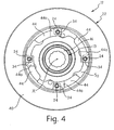
- the chain protector rotates in a reverse rotational direction relative to the sprocket S during attachment, as best understood from Figures 4 and 12-17 .
- Each of the attachment sections 44 has an axially facing contact surface 44a that is axially offset from the annular surface 46a to receive the sprocket S 1 axially therebetween.
- the slots 48 extend perpendicularly from to the axially facing contact surfaces 44a. In other words, the slots 48 have center axes that are preferably parallel to the center rotation axis.
- a circumferential slot or cutout 50 (viewable in a radial direction) extends radially outwardly from the contact surface 44a in order to receive one of the attachment flanges 34 of the sprocket S 1 therein when the chain protector 22 and the sprocket S 1 are attached together.
- the slots 50 are sized and shaped to correspond in size and shape to the portions of the attachment flanges 34 received therein, as best understood from Figures 3 , 4 , 9 and 10 .
- Each of the attachment sections 44 further includes an arc-shaped support surface 52 extending from the termination point its respective slot 50.
- the arc-shaped support surfaces 52 preferably contact an inner peripheral edge of the sprocket S 1 to provide radial support between the chain protector 22 and the sprocket S 1 .
- Each attachment section 44 having one of the axially facing surfaces 44a, one of the slots 48 and one of the slots 50 constitutes a second attachment element of the chain protector 22.
- the chain protector 22 preferably has a plurality of such second attachment elements arranged in a circumferentially spaced arrangement. Due to the above configuration, the chain protector 22 is preferably attached to the sprocket S 1 with a bayonet type mount. In other words, the first and second attachment elements of the sprocket S 1 and the chain protector 22, respectively, attach to each other via non-threaded connections. Thus, the sprocket S 1 and the chain protector 22 are preferably attached to each other in a non-threaded manner.
- the freewheel 13 is preferably assembled as a unit in a conventional manner.
- the sprockets S 1 -S 6 are non-rotatably mounted on the outer tubular member 14, as mentioned above.
- the chain protector is attached to the sprocket S 1 .
- the attachment flanges 34 are received in the slots 50 of the attachment sections 44, and the spacing portions 24c of the attachment members 24 are received in the slots 48 when the sprocket S 1 rotates in a forward direction relative to the chain protector, as seen in Figures 16 and 17 .
- the chain protector 22 can be attached to the sprocket S 1 before or after attaching in the sprockets S 1 -S 6 to the freewheel. However, the chain protector 22 is preferably attached after attaching the sprockets S 1 and S 2 together using the attachment members 24.
Landscapes
- Engineering & Computer Science (AREA)
- Mechanical Engineering (AREA)
- Chemical & Material Sciences (AREA)
- Combustion & Propulsion (AREA)
- Transportation (AREA)
- Gears, Cams (AREA)
Abstract
Description
- This invention generally relates to a bicycle sprocket assembly. More specifically, the present invention relates to a bicycle sprocket assembly having a bicycle chain protector attached to a sprocket element in response to relative rotational movement between the chain protector and the sprocket element. Background Information
- Bicycling is becoming an increasingly more popular form of recreation as well as a means of transportation. Moreover, bicycling has become a very popular competitive sport for both amateurs and professionals. Whether the bicycle is used for recreation, transportation or competition, the bicycle industry is constantly improving the various components of the bicycle. One area that has been extensively redesigned over the years is the bicycle drive train. Specifically, manufacturers of bicycle components have been continually improving shifting performance of the various shifting components such as shifters, derailleurs, chain and sprockets.
- One particular component of the drive train that has been extensively redesigned in the past years is the rear sprocket assembly. Specifically, rear sprocket assemblies have been designed with improved sprockets to provide smoother shifting. Also, rear sprocket assemblies have been provided with more rear sprockets (e.g., 7, 8, 9 or even 10 rear sprockets) to provide a larger selection of different gear ratios for the bicycle transmission. In any event, rear sprocket assemblies have also been provided with chain/spoke protectors adjacent the largest rear sprocket to prevent the chain from falling off the largest sprocket into the spokes.
- Typically, the prior chain/spoke protectors are either attached to the rear hub or attached to the largest rear sprocket using an axial snap fit. One example of such a rear sprocket assembly using an axial snap fitted protector is model CS-LG60 manufactured and sold by Shimano, Inc. While these prior spoke/chain protectors generally work well, there has been a demand for a more durable spoke/chain protector that is also relatively lightweight, and relatively simple and inexpensive to manufacture and assemble.
- In view of the above, it will be apparent to those skilled in the art from this disclosure that there exists a need for an improved bicycle sprocket assembly. This invention addresses this need in the art as well as other needs, which will become apparent to those skilled in the art from this disclosure.
- One object of the present invention is to provide a bicycle sprocket assembly with a chain protector, which prevents the chain from falling off of a sprocket into the spokes and which protects the chain from external objects such as wood or rocks.
- Another object of the present invention is to provide a bicycle sprocket assembly with a chain protector, which is relatively rigid, yet is relatively light weight.
- Another object of the present invention is to provide a bicycle sprocket assembly with a chain protector, which is relatively simple and inexpensive to manufacture and assemble.
- The foregoing objects can basically be attained by providing a bicycle sprocket assembly, which includes a sprocket element and a chain protector. The sprocket element has a plurality of teeth disposed on an outer periphery about a center rotation axis and at least one first attachment element. The chain protector includes a protecting portion and an attachment portion disposed radially inwardly of the protecting portion. The attachment portion has at least one second attachment element that mates with the first attachment element in response to relative rotational movement between the sprocket element and the chain protector.
- These and other objects, features, aspects and advantages of the present invention will become apparent to those skilled in the art from the following detailed description, which, taken in conjunction with the annexed drawings, discloses a preferred embodiment of the present invention.
- Referring now to the attached drawings which form a part of this original disclosure:
-
Figure 1 is a side elevational view of a bicycle equipped with a rear sprocket assembly having a chain protector in accordance with the present invention; -
Figure 2 is an enlarged, outside (outer axial) elevational view of the rear sprocket assembly having the chain protector illustrated inFigure 1 ; -
Figure 3 is a further enlarged, transverse, partial cross-sectional view of the rear sprocket assembly having the chain protector illustrated inFigure 2 , as viewed along section line 3-3 ofFigure 2 ; -
Figure 4 is an inside (inner axial) elevational view of the rear sprocket assembly having the chain protector illustrated inFigure 3 ; -
Figure 5 is an outside (outer axial) elevational view of the chain protector illustrated inFigures 3-4 ; -
Figure 6 is transverse, elevational view of the chain protector illustrated inFigure 5 ; -
Figure 7 is an inside (inner axial) elevational view of the chain protector illustrated inFigures 5-6 ; -
Figure 8 is a cross-sectional view of the chain protector illustrated inFigures 5-7 , as seen along section line 8-8 ofFigure 5 ; -
Figure 9 is an enlarged, partial cross-sectional view of the chain protector illustrated inFigures 5-8 , as seen along section line 9-9 ofFigure 7 , with the largest rear sprocket shown in phantom lines for the purpose of illustration; -
Figure 10 is an enlarged, partial cross-sectional view of the chain protector illustrated inFigures 5-8 , as seen along section line 10-10 ofFigure 7 , with the largest rear sprocket shown in phantom lines for the purpose of illustration; -
Figure 11 is an outside (outer axial) elevational view of the low (largest) rear sprocket of the rear sprocket assembly illustrated inFigures 2-4 , with the low (largest) sprocket removed from the remaining sprockets and with a plurality of rivets extending therefrom; -
Figure 12 is an outside (outer axial) elevational view of the low (largest) rear sprocket and the chain protector of the rear sprocket assembly illustrated inFigures 2-4 and11 , prior to attaching the chain protector; -
Figure 13 is an outside (outer axial) elevational view of the low (largest) rear sprocket and the chain protector of the rear sprocket assembly illustrated inFigures 2-4 and11 , after attaching the chain protector; -
Figure 14 is a further enlarged view of portions of the low (largest) rear sprocket and the chain protector illustrated inFigure 10 , prior to attaching the chain protector to the low (largest) rear sprocket; -
Figure 15 is a further enlarged view of portions of the low (largest) rear sprocket and the chain protector illustrated inFigure 11 , after attaching the chain protector to the low (largest) rear sprocket; -
Figure 16 is a partial perspective view of the portions of the sprocket assembly illustrated inFigure 14 ; and -
Figure 17 is a partial perspective view of the portions of the sprocket assembly illustrated inFigure 15 . - An embodiment of the present invention will now be explained with reference to the drawings. It will be apparent to those skilled in the art from this disclosure that the following descriptions of the embodiment of the present invention are provided for illustration only and not for the purpose of limiting the invention as defined by the appended claims and their equivalents.
- Referring initially to
Figure 1 , abicycle 10 having arear hub 11 with a rearmulti-stage sprocket assembly 12 attached thereto is illustrated in accordance with the present invention. Therear sprocket assembly 12 has achain protector 22 in accordance with the present invention. Specifically, themulti-stage sprocket assembly 12 preferably includes a plurality (e.g., six) rear sprockets S1-S6 non-rotatably mounted to afreewheel 13 of therear hub 11. Thechain protector 22 is mounted to attachment elements disposed between the largest rear sprocket S1 and the second largest rear sprocket S2 using a rotational movement about a center rotation axis X of therear hub 12 and therear sprocket assembly 12 in accordance with the present invention. - The
bicycle 10 is conventional, except for therear sprocket assembly 12 having thebicycle chain protector 22 attached thereto in accordance with the present invention. Accordingly, thebicycle 10 will not be explained and/or illustrated in detail herein, except as related to therear sprocket assembly 12 and thechain protector 22 in accordance with the present invention. However, it will be apparent to those skilled in the bicycle art from this disclosure that the present invention can be utilized on a variety of different bicycle types as well as utilized in conjunction with a variety of different bicycle components, as needed and/or desired. - Referring to
Figures 2-4 , thefreewheel 13 basically includes an outertubular member 14, an innertubular member 16, a one-way clutch 18 and aretaining member 20. A plurality of ball bearings are disposed between the outertubular member 14 and the innertubular member 16 in two locations as best seen inFigure 3 . The one-way clutch 18 is disposed between the outertubular member 14 and the innertubular member 16 in a conventional manner to transmit forward rotation (clockwise as viewed inFigure 2 ) of the outertubular member 14 to the innertubular member 16, but to allow the outertubular member 14 to rotate freely relative to the innertubular member 16 in a rearward direction (counter clockwise as viewed inFigure 2 ). The innertubular member 16 is preferably a step-shaped member with a splined internal surface configured to engage a mating surface of the rear hub shell (not shown). The retainingmember 20 is threaded onto the innertubular member 16 to retain the parts of the assembledfreewheel 13 together as a unit. Thefreewheel 13 operates in a conventional manner. Thus, thefreewheel 13 will not be discussed and/or illustrated in further detail herein, except as related to thesprocket assembly 12 of the present invention. - The sprockets S1-S6 are non-rotatably mounted on the outer
tubular member 14. Specifically, the outertubular member 14 includes asplined section 14a, anabutment shoulder 14b and a threadedsection 14c. The sprockets S3-S5 are slideably, non-rotatably received on thesplined section 14a with a pair ofspacers 15 received therebetween. The sprocket S3 contacts theabutment shoulder 14b. The sprocket S6 is threaded onto the threadedsection 14c to retain the sprockets S3-S5 on thesplined section 14a. The sprocket S6 has an integral spacer portion. The sprocket S1 is attached to the sprocket S2 using a plurality offirst attachment members 24. Thefirst attachment members 24 are preferably deformable metallic pins such as rivets. The sprocket S2 is attached to the sprocket S3 using a plurality ofsecond attachment members 26. Thesecond attachment members 26 are also preferably deformable metallic pins such as rivets. Thus, all of the sprockets S1-S6 are non-rotatably attached on the outertubular member 14. - Each of the first attachment members (rivets) 24 has a
first attachment end 24a attached to the sprocket S1, asecond attachment end 24b attached to the sprocket S2 and aspacing portion 24c extending axially between opposing axially facing surfaces of the sprockets S1 and S2. Similarly, each of the second attachment members (rivets) 26 has a second attachment end (not shown) attached to the sprocket S2, a third attachment end (not shown) attached to the sprocket S3 and a spacing portion extending axially between opposing axially facing surfaces of the sprockets S2 and S3. The first attachment members (rivets) 24 are arranged and configured to mate with thechain protector 22 in response to relative rotational movement between thechain protector 22 and the sprocket S1 to non-rotatably attach thechain protector 22 and the sprocket S1 together, as explained below. - Referring to
Figures 2 and3 , therear sprocket assembly 12 will now be explained in more detail. As mentioned above, in the illustrated embodiment, therear sprocket assembly 12 is a six-stage sprocket assembly with the six sprockets S1-S6 mounted on thefreewheel 13 of therear hub 11 such that the sprockets S1-S6 rotate together about the center rotation axis X. However, it will be apparent to those skilled in the bicycle art from this disclosure that therear sprocket assembly 12 can have more or fewer sprockets if needed and/or desired. - The sprockets of S1-S6 of the
multi-stage sprocket assembly 12 are configured and arranged to engage with a conventional drive chain C in a conventional manner as seen inFigure 1 . Thus, when the sprockets S1-S6 rotate together in a forward rotational direction (e.g., in a clockwise direction as viewed inFigure 2 ) due to the rider pedaling in a forward (clockwise) direction, thebicycle 10 is propelled in a forward direction as seen inFigure 1 . The chain C can be shifted between the sprockets S1-S6 by a rear derailleur in a conventional manner when the rider is pedaling in a forward direction. - Referring now to
Figures 2-4 and11 , the sprocket S1 will now be explained in more detail. The sprocket S1 is an annular plate shaped member. The sprocket S1 basically includes an annularmain body portion 30, a plurality offirst teeth 32 and aplurality attachment flanges 34. Thefirst teeth 32 are disposed about an outer periphery of the annularmain body 30 about the center rotation axis X. The attachment flanges 34 extend radially inwardly from the annularmain body portion 30. In the illustrated embodiment, four of theattachment flanges 34 are provided in a circumferentially equally spaced arrangement. Each of the attachment flanges 34 has a throughhole 36 formed therein that receives thefirst attachment end 24a of one of theattachment members 24. Theattachment members 24 and theattachment flanges 34 constitute parts of (first) attachment elements of the sprocket S1. - The sprocket S1 is preferably an annular plate shaped member as mentioned above. Thus, the sprocket S1 has first and second annular axially facing
side surface surface 30a faces away from the sprocket S2, while thesurface 30b faces toward the sprocket S2. Thespacing portions 24c of theattachment members 24 extend axially from theaxially facing surface 30b to a similar, opposed surface of the sprocket S2. The axial length of thespacing portions 24c are set such that the Sprockets S1 and S2 are spaced from each other at a prescribed interval for smooth shifting of the chain C therebetween. Theattachment members 26 space the sprockets S2 and S3 from each other in a similar manner. The sprocket S1 is preferably constructed using conventional manufacturing techniques such as stamping, punching, casting and/or machining in a conventional manner. The annularmain body portion 30, the plurality offirst teeth 32 and theplurality attachment flanges 34 are preferably integrally formed together as a one-piece, unitary member. - Accordingly, in the embodiment, the sprocket S1 constitutes a one-piece, sprocket element in accordance with the present invention. However, it will be apparent to those skilled in the bicycle art from this disclosure that the sprocket S1 could be made up of a plurality of sprocket elements (e.g., two or more arc-shaped sprocket elements with each having teeth about their outer peripheries and at least one attachment flange 34). In this embodiment, when the
first attachment members 24 are attached to the sprocket S1 (i.e., in order to attach the sprocket S1 to the sprocket S2) eachattachment flange 34 andfirst attachment member 24 attached thereto constitute parts of a first attachment element of the sprocket S1 in accordance with the present invention. Thus, the sprocket S1 preferably includes a plurality of such attachment elements that are circumferentially spaced from each other. Thespacing portions 24c of the first attachment members (rivets) 24 constitute axially extending projecting portions of the attachment elements of the sprocket S1, which extend axially from the sprocket S1. - The sprockets S2 and S3 have configurations similar to the sprocket S1. Specifically, the sprockets S2 and S3 have a plurality of chain engagement teeth similar to the sprocket S1, but have respectively smaller diameters (fewer teeth), as understood from
Figures 2-3 . The sprocket S2 has a plurality of though openings, which have the second attachment ends 24b of thefirst attachment members 24 attached therein, and a plurality of additional attachment openings, which have the second attachment ends (not shown)of thesecond attachment members 26 attached therein. The third attachment ends (not shown) of thesecond attachment members 26 are attached in similar holes of the sprocket S3. The precise construction of the sprockets S2 and S3 is not critical to the manner in which thechain protector 22 is attached, and thus, will not be explained and/or illustrated in further detail herein. - Referring now to
Figures 2-10 , thechain protector 22 will now be explained in more detail. Thechain protector 22 basically includes a protectingportion 40 and anattachment portion 42 disposed radially inwardly of the protectingportion 40. The protectingportion 40 has an annular conical disc-shaped configuration, as best understood fromFigures 3-8 . Theattachment portion 42 includes a plurality ofattachment sections 44 configured and arranged to be attached to thefirst attachment members 24 and theattachment flanges 34. In the illustrated embodiment, four of theattachment sections 44 are provided in a circumferentially equally spaced arrangement so as to mate with theattachment members 24 extending from theattachment flanges 34. - A connecting
portion 46 extends axially between the protectingportion 40 and theattachment portion 42 in a stepped arrangement, as best understood fromFigure 8 . Thus, theattachment sections 44 are preferably axially offset from the protectingportion 40. The connectingportion 46 has a continuous annular configuration with anannular surface 46a that contacts theaxially facing surface 30a of the sprocket S1 radially inwardly of thefirst teeth 32, as best seen inFigures 3 ,5 ,6 and8 . Thus, the protectingportion 40 preferably radially overlaps with thefirst teeth 32 of the sprocket S1 as viewed along the center rotation axis X. - Preferably, the protecting
portion 40, theattachment portion 42 having theattachment sections 44, and the connectingportion 46 are integrally formed together as a one-piece, unitary member from a light weight, rigid material such as a plastic material using conventional manufacturing techniques such as casting or the like. However, it will be apparent to those skilled in the bicycle art from this disclosure that thechain protector 22 and/or the protectingportion 40, theattachment portion 42 having theattachment sections 44, and the connectingportion 46 can be constructed of several different parts and/or materials, if needed and/or desired. - Each of the
attachment sections 44 includes aslot 48 having aninsertion portion 48a, a (rivet) retainingportion 48b and a holdingportion 48c. Eachinsertion portion 48a is wider than a width W1 of thespacing portions 24c. Theinsertion portions 48a are configured and arranged to guide thespacing portions 24c toward the holdingportions 48c of theslots 48. The retainingportions 48b of theslots 48 each have a width that is preferably smaller than the width W1 of thespacing portions 24c of theattachment members 24. Specifically, each retainingportion 48b preferably has projection or tooth that is deformable so as to receive thespacing portion 24c in a snap-fit type connection into the holdingportion 48c. The holdingportions 48c are where thespacing portions 24c of therespective attachment members 24 are seated in a fully installed position, i.e., after moving circumferentially past the retainingportions 48b. The size and shape of the holdingportion 48c corresponds to the size and shape of thespacing portions 24c. - The
slots 48 extend in a circumferential direction about the center rotation axis X. Specifically, theinsertion portions 48a are circumferentially disposed relative to the retainingportions 48b, and the retainingportions 48b are circumferentially disposed relative to the holdingportions 48c. Thus, thechain protector 22 is preferably attached to the sprocket S1 when thechain protector 22 and the sprocket S1 rotated relative to each other via a bayonet-type mount. Preferably, the sprocket S1 rotates in a forward rotational direction relative to thechain protector 22 during attachment. In other words, the chain protector rotates in a reverse rotational direction relative to the sprocket S during attachment, as best understood fromFigures 4 and12-17 . - Each of the
attachment sections 44 has an axially facingcontact surface 44a that is axially offset from theannular surface 46a to receive the sprocket S1 axially therebetween. Theslots 48 extend perpendicularly from to the axially facingcontact surfaces 44a. In other words, theslots 48 have center axes that are preferably parallel to the center rotation axis. A circumferential slot or cutout 50 (viewable in a radial direction) extends radially outwardly from thecontact surface 44a in order to receive one of theattachment flanges 34 of the sprocket S1 therein when thechain protector 22 and the sprocket S1 are attached together. Theslots 50 are sized and shaped to correspond in size and shape to the portions of theattachment flanges 34 received therein, as best understood fromFigures 3 ,4 ,9 and 10 . Each of theattachment sections 44 further includes an arc-shapedsupport surface 52 extending from the termination point itsrespective slot 50. The arc-shaped support surfaces 52 preferably contact an inner peripheral edge of the sprocket S1 to provide radial support between thechain protector 22 and the sprocket S1. - Each
attachment section 44 having one of theaxially facing surfaces 44a, one of theslots 48 and one of theslots 50 constitutes a second attachment element of thechain protector 22. Thus, thechain protector 22 preferably has a plurality of such second attachment elements arranged in a circumferentially spaced arrangement. Due to the above configuration, thechain protector 22 is preferably attached to the sprocket S1 with a bayonet type mount. In other words, the first and second attachment elements of the sprocket S1 and thechain protector 22, respectively, attach to each other via non-threaded connections. Thus, the sprocket S1 and thechain protector 22 are preferably attached to each other in a non-threaded manner. - Referring now to
Figures 9-17 , attachment of thechain protector 22 to the sprocket S1 will now be explained. Thefreewheel 13 is preferably assembled as a unit in a conventional manner. The sprockets S1-S6 are non-rotatably mounted on the outertubular member 14, as mentioned above. The chain protector is attached to the sprocket S1. Specifically, theattachment flanges 34 are received in theslots 50 of theattachment sections 44, and thespacing portions 24c of theattachment members 24 are received in theslots 48 when the sprocket S1 rotates in a forward direction relative to the chain protector, as seen inFigures 16 and 17 . Thechain protector 22 can be attached to the sprocket S1 before or after attaching in the sprockets S1-S6 to the freewheel. However, thechain protector 22 is preferably attached after attaching the sprockets S1 and S2 together using theattachment members 24. - In understanding the scope of the present invention, the term "comprising" and its derivatives, as used herein, are intended to be open ended terms that specify the presence of the stated features, elements, components and/or steps, but do not exclude the presence of other unstated features, elements, components and/or steps. The foregoing also applies to words having similar meanings such as the terms, "including", "having" and their derivatives. Also, the terms "part," "section," "portion," "member" or "element" when used in the singular can have the dual meaning of a single part or a plurality of parts. As used herein to describe the present invention, the following directional terms "forward, rearward, above, downward, vertical, horizontal, below and transverse" as well as any other similar directional terms refer to those directions of a bicycle equipped with the present invention. Accordingly, these terms, as utilized to describe the present invention should be interpreted relative to a bicycle equipped with the present invention as used in the normal riding position. Finally, terms of degree such as "substantially", "about" and "approximately" as used herein mean a reasonable amount of deviation of the modified term such that the end result is not significantly changed.
- While only a selected embodiment has been chosen to illustrate the present invention, it will be apparent to those skilled in the art from this disclosure that various changes and modifications can be made herein without departing from the scope of the invention as defined in the appended claims. Furthermore, the foregoing descriptions of the embodiment according to the present invention are provided for illustration only, and not for the purpose of limiting the invention as defined by the appended claims and their equivalents.
Claims (7)
- A bicycle sprocket assembly (12) characterized in that it comprises:a sprocket element (S1) having a plurality of teeth (32) disposed on an outer periphery about a center rotation axis (X) and at least one first attachment element (24,34) ; anda chain protector (22) including a protecting portion (40) and an attachment portion (42) disposed radially inwardly of the protecting portion (40), the attachment portion (42) has at least one second attachment element (44) that mates with the first attachment element (24, 34) in response to relative rotational movement between the sprocket element (S1) and the chain protector (22).
- The bicycle sprocket assembly (12) according to claim 1, characterized in that
the first attachment element (24, 34) includes an axially extending projecting portion (34), and the second attachment element (44) includes a slot (48). - The bicycle sprocket assembly (12) according to claim 2, characterized in that
the slot (48) extends in a circumferential direction about the center rotation axis (X) such that the projecting portion (34) mates with the slot (48) in response to relative rotational movement between the sprocket element (S1) and the chain protector (22) about the center rotation axis (X). - The bicycle sprocket assembly (12) according to any one of claims 1 to 3, characterized in that
the sprocket element (S1) has a plurality of circumferentially spaced first attachment elements (24,34) , and the attachment portion (42) of the bicycle chain protector (22) has a plurality of circumferentially spaced second attachment elements (44). - The bicycle sprocket assembly (12) according to claim 4, characterized in that
the first and second attachment elements (24, 34; 44) attach via a non-threaded connection. - The bicycle sprocket assembly (12) according to claim 5, characterized in that
the first and second attachment elements (24,34;44) attach via a bayonet-type mount. - The bicycle sprocket assembly (12) according to any one of claims 1 to 6, characterized in that
the sprocket element (S1) is constructed of a metallic material and the bicycle chain protector (22) is constructed of a plastic material.
Applications Claiming Priority (1)
| Application Number | Priority Date | Filing Date | Title |
|---|---|---|---|
| US11/752,762 US8888629B2 (en) | 2007-05-23 | 2007-05-23 | Bicycle sprocket assembly with chain protector |
Publications (3)
| Publication Number | Publication Date |
|---|---|
| EP1995166A2 true EP1995166A2 (en) | 2008-11-26 |
| EP1995166A3 EP1995166A3 (en) | 2008-12-03 |
| EP1995166B1 EP1995166B1 (en) | 2016-06-08 |
Family
ID=38705140
Family Applications (1)
| Application Number | Title | Priority Date | Filing Date |
|---|---|---|---|
| EP07119504.4A Active EP1995166B1 (en) | 2007-05-23 | 2007-10-29 | Bicycle sprocket assembley with chain protector |
Country Status (4)
| Country | Link |
|---|---|
| US (1) | US8888629B2 (en) |
| EP (1) | EP1995166B1 (en) |
| CN (1) | CN101311059B (en) |
| TW (1) | TWI355353B (en) |
Cited By (5)
| Publication number | Priority date | Publication date | Assignee | Title |
|---|---|---|---|---|
| WO2015092347A1 (en) * | 2013-12-18 | 2015-06-25 | Bopworx Limited | Chainring protector |
| WO2019040340A1 (en) | 2017-08-21 | 2019-02-28 | The Hive Global, Inc. | Bicycle cassette with clamping connection |
| US11485449B2 (en) | 2015-09-01 | 2022-11-01 | The Hive Global, Inc. | Bicycle cassette with locking connection |
| US11932351B2 (en) | 2020-07-17 | 2024-03-19 | The Hive Global, Inc. | Conical bicycle cassette sprocket structure |
| US12030586B2 (en) | 2021-07-12 | 2024-07-09 | The Hive Global, Inc. | Seal for bicycle crank with differential chainring motion |
Families Citing this family (14)
| Publication number | Priority date | Publication date | Assignee | Title |
|---|---|---|---|---|
| US8696503B2 (en) * | 2011-03-01 | 2014-04-15 | Shimano Inc. | Bicycle sprocket assembly |
| US8882130B2 (en) * | 2012-10-11 | 2014-11-11 | Shimano Inc. | Bicycle drive assembly |
| US10221887B2 (en) | 2012-12-06 | 2019-03-05 | The Hive Global, Inc | Self locking bearing preload adjuster |
| US9533735B2 (en) * | 2013-07-19 | 2017-01-03 | Sram Deutschland Gmbh | Multiple-sprocket arrangement for a bicycle gearing |
| DE102014115654B4 (en) * | 2013-10-28 | 2018-11-15 | Miranda & Irmão, Lda. | KETTENSCHUTZ SYSTEM |
| US11142280B2 (en) | 2016-03-24 | 2021-10-12 | The Hive Global, Inc. | Bicycle crank with spindle attachment structure |
| AT518781B1 (en) * | 2016-12-19 | 2018-01-15 | Miba Sinter Austria Gmbh | pulley |
| US10315727B2 (en) * | 2017-02-16 | 2019-06-11 | Shimano Inc. | Bicycle rear sprocket assembly |
| US10618588B2 (en) | 2017-12-13 | 2020-04-14 | Gates Corporation | Sprocket guard |
| US10780947B2 (en) * | 2018-06-19 | 2020-09-22 | Hao Meng Bicycle (Shanghai) Co., Ltd | Automatic return structure for chain detachment of bicycle |
| EP3647170B1 (en) * | 2018-10-29 | 2024-07-31 | Miranda & Irmão Lda. | Crank set with chain guard ring and fastening element |
| US12358593B2 (en) * | 2021-01-15 | 2025-07-15 | Sram, Llc | Bash guard device and system for bicycle components |
| US12233975B2 (en) | 2021-03-26 | 2025-02-25 | The Hive Global Inc. | Telescopic bicycle seatpost with adjustable height and fixed frame insertion |
| TWI846167B (en) * | 2022-11-25 | 2024-06-21 | 彥豪金屬工業股份有限公司 | Bicycle rear cassette |
Family Cites Families (39)
| Publication number | Priority date | Publication date | Assignee | Title |
|---|---|---|---|---|
| US504121A (en) * | 1893-08-29 | Bicycle-crank shield | ||
| US877820A (en) * | 1907-03-19 | 1908-01-28 | Benjamin Moss Badger | Bicycle attachment. |
| US1136411A (en) * | 1914-07-17 | 1915-04-20 | Adolphus O Davis | Sprocket-guard for cycles. |
| US1567638A (en) * | 1925-02-12 | 1925-12-29 | F A Whitney Carriage Company | Hub |
| US1643611A (en) * | 1925-04-11 | 1927-09-27 | Cie D Applic Mechaniques | Split pulley |
| GB573423A (en) | 1943-11-27 | 1945-11-20 | Birmingham Small Arms Co Ltd | Improvements in or relating to the manufacture of wheel hubs for cycles |
| US2610514A (en) * | 1948-07-22 | 1952-09-16 | Jr Ballard Emerson Long | Sheave |
| US3170549A (en) * | 1961-06-23 | 1965-02-23 | Gregory Ind | Bicycle coaster brake |
| US3168836A (en) * | 1963-03-05 | 1965-02-09 | Frank A Militana | Sprocket with a replaceable wear rim for a crawler type vehicle |
| US3494227A (en) * | 1967-06-20 | 1970-02-10 | Shimano Industrial Co | Bicycle hub having a built-in two stage speed change mechanism |
| US3477303A (en) * | 1967-11-28 | 1969-11-11 | Schwinn Bicycle Co | Double plateau sprocket assembly |
| US3835729A (en) * | 1971-11-27 | 1974-09-17 | Shimano Industrial Co | Means for preventing driving chain from coming off multi-speed transmission front gear for bicycle |
| US3815439A (en) * | 1972-10-20 | 1974-06-11 | Shimano Industrial Co | Multi-speed transmission front gear system |
| JPS5427719Y2 (en) | 1975-05-24 | 1979-09-07 | ||
| US4044621A (en) * | 1975-06-09 | 1977-08-30 | Mcgregor Sr John C | Sprocket structure and chain guard |
| US4145095A (en) * | 1975-07-10 | 1979-03-20 | Shimano Industrial Company Limited | Hub with free wheel for a bicycle |
| GB1555532A (en) | 1975-07-10 | 1979-11-14 | Shimano Industrial Co | Unit hub for a giycle |
| US4116319A (en) * | 1976-05-25 | 1978-09-26 | Shimano Industrial Company Limited | Rear gear for a bicycle |
| US4144773A (en) * | 1976-07-12 | 1979-03-20 | Addicks Lyle F | Bicycle sprocket wheel |
| JPS5612083Y2 (en) * | 1977-09-29 | 1981-03-19 | ||
| JPS5736488Y2 (en) * | 1978-04-14 | 1982-08-12 | ||
| JPS5631511Y2 (en) | 1978-04-20 | 1981-07-27 | ||
| US4240303A (en) * | 1978-09-27 | 1980-12-23 | Mosley Earnest D | Chain sprocket with opposite frangible side guide plates |
| JPS57188592U (en) * | 1981-05-27 | 1982-11-30 | ||
| JPS5941916U (en) | 1982-09-10 | 1984-03-17 | 筒井 肇 | Lighting system inside the Buddhist altar |
| JPS59164423A (en) * | 1983-03-07 | 1984-09-17 | Maeda Kogyo Kk | Clutch device in unit hub for bicycle or hub with coaster brake |
| JPS60149484U (en) | 1984-03-15 | 1985-10-04 | 株式会社シマノ | Multi-stage front chain gear for bicycles |
| FR2577507A1 (en) | 1985-02-15 | 1986-08-22 | Maillard Maurice Ets | ANTI-FRESH FLASK FOR CHAIN ASSOCIATED WITH A CYCLE FREE WHEEL |
| DE3523358A1 (en) | 1985-03-20 | 1986-10-02 | H. Hemmelskamp Metall- und Kunststoffwarenfabrik, 4800 Bielefeld | Spoke-protection disc provided with a hub bore |
| US5003840A (en) * | 1989-11-06 | 1991-04-02 | Huffy Corporation | Cover for the driving sprocket of a bicycle |
| JP2563661Y2 (en) | 1991-07-29 | 1998-02-25 | 株式会社シマノ | Bicycle safety cover |
| JPH0667289U (en) * | 1993-03-09 | 1994-09-22 | 株式会社シマノ | Bicycle front gear unit and bicycle crank used in this front gear unit |
| JP2606244Y2 (en) | 1993-03-09 | 2000-10-10 | 株式会社シマノ | Bicycle front gear |
| CH686796A5 (en) | 1995-02-08 | 1996-06-28 | Walter Koechli | Bearing assembly for bicycle wheel |
| CN2228041Y (en) | 1995-09-29 | 1996-05-29 | 捷安特(中国)有限公司 | Protctive disk for cycle freewheel |
| JP3204929B2 (en) * | 1997-08-08 | 2001-09-04 | 株式会社シマノ | Interior gear hub for bicycle |
| US6380731B1 (en) * | 1999-11-24 | 2002-04-30 | Shimano, Inc. | Motor unit with an integrated speed sensor for a bicycle hub transmission |
| US6475110B1 (en) * | 2000-03-17 | 2002-11-05 | Shimano Inc. | Bicycle front chainwheel assembly |
| DE50207478D1 (en) | 2001-08-27 | 2006-08-24 | Rixen & Kaul Gmbh | Pedalarm of a bicycle |
-
2007
- 2007-05-23 US US11/752,762 patent/US8888629B2/en not_active Expired - Fee Related
- 2007-10-22 TW TW96139501A patent/TWI355353B/en active
- 2007-10-29 EP EP07119504.4A patent/EP1995166B1/en active Active
- 2007-11-16 CN CN 200710169470 patent/CN101311059B/en active Active
Cited By (7)
| Publication number | Priority date | Publication date | Assignee | Title |
|---|---|---|---|---|
| WO2015092347A1 (en) * | 2013-12-18 | 2015-06-25 | Bopworx Limited | Chainring protector |
| US11485449B2 (en) | 2015-09-01 | 2022-11-01 | The Hive Global, Inc. | Bicycle cassette with locking connection |
| WO2019040340A1 (en) | 2017-08-21 | 2019-02-28 | The Hive Global, Inc. | Bicycle cassette with clamping connection |
| EP3672864A4 (en) * | 2017-08-21 | 2021-04-14 | The Hive Global, Inc. | BICYCLE CASSETTE INCLUDING A CLAMP CONNECTION |
| US11351815B2 (en) | 2017-08-21 | 2022-06-07 | The Hive Global, Inc. | Bicycle cassette with clamping connection |
| US11932351B2 (en) | 2020-07-17 | 2024-03-19 | The Hive Global, Inc. | Conical bicycle cassette sprocket structure |
| US12030586B2 (en) | 2021-07-12 | 2024-07-09 | The Hive Global, Inc. | Seal for bicycle crank with differential chainring motion |
Also Published As
| Publication number | Publication date |
|---|---|
| US8888629B2 (en) | 2014-11-18 |
| TW200909299A (en) | 2009-03-01 |
| CN101311059A (en) | 2008-11-26 |
| EP1995166A3 (en) | 2008-12-03 |
| EP1995166B1 (en) | 2016-06-08 |
| CN101311059B (en) | 2013-05-22 |
| TWI355353B (en) | 2012-01-01 |
| US20080289927A1 (en) | 2008-11-27 |
Similar Documents
| Publication | Publication Date | Title |
|---|---|---|
| EP1995166B1 (en) | Bicycle sprocket assembley with chain protector | |
| US7854673B2 (en) | Bicycle sprocket assembly having a reinforcement member coupled between sprockets | |
| US8905878B2 (en) | Bicycle sprocket assembly | |
| EP2452865B2 (en) | Sprocket support structure | |
| US7435197B2 (en) | Rear sprocket for bicycle transmission | |
| US7871347B2 (en) | Bicycle rear sprocket assembly | |
| US10507690B2 (en) | Bicycle hub assembly | |
| CN107521610B (en) | Multiple bicycle sprocket assembly | |
| EP2495161B1 (en) | Bicycle sprocket assembly | |
| EP2554468B1 (en) | Bicycle sprocket assembly | |
| US10112681B2 (en) | Bicycle sprocket supporting member and bicycle sprocket assembly | |
| US10773772B2 (en) | Bicycle sprocket assembly | |
| US12286195B2 (en) | Bicycle rear sprocket assembly | |
| TWI702168B (en) | Bicycle sprocket assembly | |
| US20080004143A1 (en) | Bicycle sprocket assembly | |
| US10618597B2 (en) | Bicycle sprocket assembly | |
| US11642913B2 (en) | Sprocket support body and bicycle hub assembly |
Legal Events
| Date | Code | Title | Description |
|---|---|---|---|
| PUAI | Public reference made under article 153(3) epc to a published international application that has entered the european phase |
Free format text: ORIGINAL CODE: 0009012 |
|
| PUAL | Search report despatched |
Free format text: ORIGINAL CODE: 0009013 |
|
| AK | Designated contracting states |
Kind code of ref document: A2 Designated state(s): AT BE BG CH CY CZ DE DK EE ES FI FR GB GR HU IE IS IT LI LT LU LV MC MT NL PL PT RO SE SI SK TR |
|
| AX | Request for extension of the european patent |
Extension state: AL BA HR MK RS |
|
| AK | Designated contracting states |
Kind code of ref document: A3 Designated state(s): AT BE BG CH CY CZ DE DK EE ES FI FR GB GR HU IE IS IT LI LT LU LV MC MT NL PL PT RO SE SI SK TR |
|
| AX | Request for extension of the european patent |
Extension state: AL BA HR MK RS |
|
| RIC1 | Information provided on ipc code assigned before grant |
Ipc: B62M 9/10 20060101AFI20071129BHEP Ipc: B62J 13/00 20060101ALI20081030BHEP Ipc: B62M 9/12 20060101ALI20081030BHEP |
|
| 17P | Request for examination filed |
Effective date: 20090226 |
|
| 17Q | First examination report despatched |
Effective date: 20090326 |
|
| AKX | Designation fees paid |
Designated state(s): DE FR IT |
|
| GRAP | Despatch of communication of intention to grant a patent |
Free format text: ORIGINAL CODE: EPIDOSNIGR1 |
|
| INTG | Intention to grant announced |
Effective date: 20160128 |
|
| GRAS | Grant fee paid |
Free format text: ORIGINAL CODE: EPIDOSNIGR3 |
|
| GRAA | (expected) grant |
Free format text: ORIGINAL CODE: 0009210 |
|
| AK | Designated contracting states |
Kind code of ref document: B1 Designated state(s): DE FR IT |
|
| REG | Reference to a national code |
Ref country code: DE Ref legal event code: R096 Ref document number: 602007046572 Country of ref document: DE |
|
| PGFP | Annual fee paid to national office [announced via postgrant information from national office to epo] |
Ref country code: IT Payment date: 20161013 Year of fee payment: 10 |
|
| REG | Reference to a national code |
Ref country code: DE Ref legal event code: R097 Ref document number: 602007046572 Country of ref document: DE |
|
| PLBE | No opposition filed within time limit |
Free format text: ORIGINAL CODE: 0009261 |
|
| STAA | Information on the status of an ep patent application or granted ep patent |
Free format text: STATUS: NO OPPOSITION FILED WITHIN TIME LIMIT |
|
| 26N | No opposition filed |
Effective date: 20170309 |
|
| REG | Reference to a national code |
Ref country code: FR Ref legal event code: ST Effective date: 20170630 |
|
| PG25 | Lapsed in a contracting state [announced via postgrant information from national office to epo] |
Ref country code: FR Free format text: LAPSE BECAUSE OF NON-PAYMENT OF DUE FEES Effective date: 20161102 |
|
| PG25 | Lapsed in a contracting state [announced via postgrant information from national office to epo] |
Ref country code: IT Free format text: LAPSE BECAUSE OF NON-PAYMENT OF DUE FEES Effective date: 20171029 |
|
| REG | Reference to a national code |
Ref country code: DE Ref legal event code: R082 Ref document number: 602007046572 Country of ref document: DE Representative=s name: CBDL PATENTANWAELTE GBR, DE Ref country code: DE Ref legal event code: R082 Ref document number: 602007046572 Country of ref document: DE Representative=s name: CBDL PATENTANWAELTE EGBR, DE |
|
| P01 | Opt-out of the competence of the unified patent court (upc) registered |
Effective date: 20230428 |
|
| PGFP | Annual fee paid to national office [announced via postgrant information from national office to epo] |
Ref country code: DE Payment date: 20251021 Year of fee payment: 19 |