EP1995092A1 - Air treatment assembly for vehicles - Google Patents
Air treatment assembly for vehicles Download PDFInfo
- Publication number
- EP1995092A1 EP1995092A1 EP07425308A EP07425308A EP1995092A1 EP 1995092 A1 EP1995092 A1 EP 1995092A1 EP 07425308 A EP07425308 A EP 07425308A EP 07425308 A EP07425308 A EP 07425308A EP 1995092 A1 EP1995092 A1 EP 1995092A1
- Authority
- EP
- European Patent Office
- Prior art keywords
- sealing element
- air treatment
- exchanger
- seat
- treatment assembly
- Prior art date
- Legal status (The legal status is an assumption and is not a legal conclusion. Google has not performed a legal analysis and makes no representation as to the accuracy of the status listed.)
- Granted
Links
Images


Classifications
-
- B—PERFORMING OPERATIONS; TRANSPORTING
- B60—VEHICLES IN GENERAL
- B60H—ARRANGEMENTS OF HEATING, COOLING, VENTILATING OR OTHER AIR-TREATING DEVICES SPECIALLY ADAPTED FOR PASSENGER OR GOODS SPACES OF VEHICLES
- B60H1/00—Heating, cooling or ventilating devices
- B60H1/00507—Details, e.g. mounting arrangements, desaeration devices
- B60H1/00514—Details of air conditioning housings
- B60H1/00521—Mounting or fastening of components in housings, e.g. heat exchangers, fans, electronic regulators
-
- B—PERFORMING OPERATIONS; TRANSPORTING
- B60—VEHICLES IN GENERAL
- B60H—ARRANGEMENTS OF HEATING, COOLING, VENTILATING OR OTHER AIR-TREATING DEVICES SPECIALLY ADAPTED FOR PASSENGER OR GOODS SPACES OF VEHICLES
- B60H1/00—Heating, cooling or ventilating devices
- B60H1/00507—Details, e.g. mounting arrangements, desaeration devices
- B60H2001/00621—Fastening lids on air-conditioning housings
Definitions
- the present invention relates to an air treatment assembly for vehicles of the type comprising:
- An air treatment assembly with the above characteristics is, for example, known from European patent application EP-A-1 700 722 in the name of the same applicant.
- the assembly described in that document has a main body in which a number of seats are formed.
- the components necessary for operation of the assembly (heat exchanger, evaporator, etc) are slidably inserted inside their respective seats and held in place by fastening elements of the "bridge" type. These fastening elements are detached and independent with regard to the main body. This increases the number of components of the assembly and involves additional operations for application of the fastening elements. These fastening elements might also be mislaid during maintenance operations.
- the purpose of the present invention is to improve air treatment assemblies of the type described and in particular to reduce the number of components and improve the hold of the heat exchanger in the main body. Further objects of the present invention concern improving the seal of the heat exchange assembly versus the external environment and at the same time reducing noisiness thanks to more efficient damping of vibrations.
- an air treatment assembly for vehicles of the type indicated above characterised in that the fastening arrangement comprises an annular sealing element of elastomeric material having an inner surface and an outer surface, in which the inner surface is anchored to the base plate such that it is constrained to the exchanger along said longitudinal direction, and in that said sealing element presents on its external surface projecting formations which, during insertion of the exchanger into said seat, are deformed in contact with at least one surface of said opening in a contrary direction to that of insertion, said projecting formations causing a condition of compression of the sealing element that constrains the exchanger by friction along a direction contrary to that of insertion.
- reference number 10 indicates an air treatment assembly for vehicles according to the invention.
- the air treatment assembly 10 is a system capable of producing a flow of treated air, that may be heated, conditioned, etc, destined subsequently to be conveyed into the passenger compartment of a vehicle.
- An assembly of this type typically includes a fan, heat exchangers and a system of ducts to convey the flow of air through the exchangers and subsequently towards the vehicle's passenger compartment.
- the assembly 10 comprises a casing 12, obtained through injection moulding of plastic material, in which a seat 14 is formed having an opening onto the surface of the casing 12, that may be totally or partially surrounded by surfaces 16.
- the seat 14 extends from the opening towards the inside of the casing 12 along a direction substantially perpendicular to the opening.
- a heat exchanger 18 having a heat exchange core 18a comprising tubes with axes parallel to each other, and fins that connect the tubes transversely.
- the heat exchange core is delimited at the opposite ends by two base plates 18b, only one of which is shown in the figures.
- Each base plate 18b is sealed to a collector tank 18c through folding of its edge 20.
- the heat exchanger is a component known per se, thus further construction details are omitted so as not to burden the description and the attached drawings with details that are not within the scope of the present invention.
- the heat exchanger 18 is inserted into the seat 14 of the casing 12 in the general manner of a "drawer".
- the fastening arrangement holding the exchanger 18 in its seat 14 comprise an annular sealing element 22 of elastomeric material.
- the sealing element 22 has an inner surface 24 and an outer surface 26; these surfaces are destined respectively to co-operate with the heat exchanger 18 and with the surfaces 16 of the seat 14.
- a first portion 24a and a second portion 24b of the inner surface 24 extend in contact with the heat exchange core 18a and with the collector tank 18c. Between the first portion 24a and the second portion 24b an annular hollow 25 is obtained in which is housed the edge 20 of the base plate 18b.
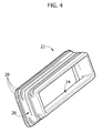
- the sealing element 22 shown in figure 4 has a substantially rectangular annular shape and presents three projecting formations on its longer sides and two on its shorter sides.
- the sealing element 22 is assembled onto the exchanger 18.
- the first portion 24a and the second portion 24b of the inner surface 24 are placed in contact respectively with the surfaces of the heat exchange core 18a and of the collector tank 18c, whereas the edge 20 is positioned in the annular hollow 25.
- This type of assembly provides the sealing element 22 with a secure hold on the body of the exchanger 18 along the longitudinal direction.
- the exchanger 18 is introduced into the seat 14 from the part opposite the collector tank 18c.
- the projecting formations 28 of the sealing element 22 are deformed against the surfaces 16 along a direction that is contrary to that of insertion.
- the inclined direction of the projecting formations 28, which is with the direction of insertion makes it easy to introduce the exchanger 18 in the seat 14 up to the stop. In this way the exchanger 18 is efficaciously held along all directions. Indeed, movements of the exchanger in the plane perpendicular to its longitudinal direction, that is in the plane perpendicular to the principal direction of the seat 14, are strongly attenuated thanks to the elastic action typical of the sealing element 22.
- the exchanger 18 is also locked against extraction by the projecting formations 28, that are compressed by the surfaces 16 of the seat 14. During insertion, the projecting formations 28 have been deformed by the surfaces 16 and the result is a condition of compression of the sealing element 22.
- a further advantage with regard to known techniques consists in an improved seal of the heat exchange assembly versus the external environment, thanks to the insulating function that the deformed projecting formations play when the exchanger is inserted into its seat.
- the sealing element of elastomeric material also provides attenuation of the vibrations of the exchanger and of the casing, with a consequent reduction in the noisiness of the heat exchange assembly.
Landscapes
- Physics & Mathematics (AREA)
- Thermal Sciences (AREA)
- Engineering & Computer Science (AREA)
- Mechanical Engineering (AREA)
- Air-Conditioning For Vehicles (AREA)
- Heat-Exchange Devices With Radiators And Conduit Assemblies (AREA)
Abstract
- an outer casing of plastic material having at least one seat, said seat having an opening on the surface of said casing and extending along a main direction oriented substantially perpendicularly to said opening,
- at least one heat exchanger comprising a tube-and-fin heat exchange core comprising a plurality of tubes with axes parallel to each other extending in a longitudinal direction, a base plate fixed to the ends of the pipes and a collector tank sealed to said base plate, said exchanger having a cross-section with a shape corresponding to that of said opening and being intended to be inserted in said seat along a direction parallel to said longitudinal direction according to a generally drawer-like arrangement, and
- fastening means to hold the exchanger in said seat.
Description
- The present invention relates to an air treatment assembly for vehicles of the type comprising:
- an external casing of plastic material having at least one seat, said seat having an opening on the surface of said casing and extending along a main direction oriented substantially perpendicularly to said opening,
- at least one heat exchanger including a pipe-and-fin heat exchange core comprising a plurality of pipes with axes parallel to each other extending longitudinally, a base plate fixed to the ends of the pipes and a collecting tank sealed to said base plate, said exchanger having a cross-section with a shape corresponding to that of said opening and being intended to be inserted into said seat along a direction parallel to said longitudinal direction according to a generally drawer-like arrangment, and
- a fastening arrangement to hold the exchanger in said seat.
- An air treatment assembly with the above characteristics is, for example, known from European patent application
EP-A-1 700 722 in the name of the same applicant. The assembly described in that document has a main body in which a number of seats are formed. The components necessary for operation of the assembly (heat exchanger, evaporator, etc) are slidably inserted inside their respective seats and held in place by fastening elements of the "bridge" type. These fastening elements are detached and independent with regard to the main body. This increases the number of components of the assembly and involves additional operations for application of the fastening elements. These fastening elements might also be mislaid during maintenance operations. During operation of the heat exchange assembly, furthermore, a draft of air is forced to pass through the heat exchanger and this induces localised over-pressure in the pipes upstream of it. It has been observed that this over-pressure causes a loss of airflow with consequent reduced performance of the assembly. Again during operation it has also been observed that a certain amount of noise is produced due to the vibrations to which both the exchanger and the casing of the heat exchange assembly are subjected. - The purpose of the present invention is to improve air treatment assemblies of the type described and in particular to reduce the number of components and improve the hold of the heat exchanger in the main body. Further objects of the present invention concern improving the seal of the heat exchange assembly versus the external environment and at the same time reducing noisiness thanks to more efficient damping of vibrations.
- These and other goals are achieved by an air treatment assembly for vehicles of the type indicated above, and characterised in that the fastening arrangement comprises an annular sealing element of elastomeric material having an inner surface and an outer surface, in which the inner surface is anchored to the base plate such that it is constrained to the exchanger along said longitudinal direction, and in that said sealing element presents on its external surface projecting formations which, during insertion of the exchanger into said seat, are deformed in contact with at least one surface of said opening in a contrary direction to that of insertion, said projecting formations causing a condition of compression of the sealing element that constrains the exchanger by friction along a direction contrary to that of insertion.
- The present invention will now be described with reference to the attached drawings, provided purely by way of non-limiting example, in which:
-
figure 1 is a partial perspective view of an air treatment assembly according to the present invention, -
figure 2 is a cross-section along line II-II infigure 1 , -
figure 3 is an enlarged detail of the part indicated by arrow III infigure 2 , and -
figure 4 is a perspective view of a sealing element according to the invention. - With reference to
figure 1 ,reference number 10 indicates an air treatment assembly for vehicles according to the invention. Theair treatment assembly 10 is a system capable of producing a flow of treated air, that may be heated, conditioned, etc, destined subsequently to be conveyed into the passenger compartment of a vehicle. An assembly of this type typically includes a fan, heat exchangers and a system of ducts to convey the flow of air through the exchangers and subsequently towards the vehicle's passenger compartment. - The
assembly 10 comprises acasing 12, obtained through injection moulding of plastic material, in which aseat 14 is formed having an opening onto the surface of thecasing 12, that may be totally or partially surrounded bysurfaces 16. Theseat 14 extends from the opening towards the inside of thecasing 12 along a direction substantially perpendicular to the opening. - In the
seat 14 is housed aheat exchanger 18 having aheat exchange core 18a comprising tubes with axes parallel to each other, and fins that connect the tubes transversely. The heat exchange core is delimited at the opposite ends by twobase plates 18b, only one of which is shown in the figures. Eachbase plate 18b is sealed to acollector tank 18c through folding of itsedge 20. The heat exchanger is a component known per se, thus further construction details are omitted so as not to burden the description and the attached drawings with details that are not within the scope of the present invention. - The
heat exchanger 18 is inserted into theseat 14 of thecasing 12 in the general manner of a "drawer". - According to the present invention, the fastening arrangement holding the
exchanger 18 in itsseat 14 comprise anannular sealing element 22 of elastomeric material. Thesealing element 22 has aninner surface 24 and anouter surface 26; these surfaces are destined respectively to co-operate with theheat exchanger 18 and with thesurfaces 16 of theseat 14. - With reference to
figures 2 and3 , afirst portion 24a and asecond portion 24b of theinner surface 24 extend in contact with theheat exchange core 18a and with thecollector tank 18c. Between thefirst portion 24a and thesecond portion 24b anannular hollow 25 is obtained in which is housed theedge 20 of thebase plate 18b. Naturally, any changes in the geometry of theexchanger 18 and of the way in which the heat exchangecore 18a and thecollector tank 18c are coupled will lead to respective changes in the conformation of theinner surface 24 of thesealing element 22. - On the
external surface 26 of thesealing element 22 around the entire annularextension projecting formations 28 are obtained, that extend radially along a direction that is inclined with regard to the longitudinal direction of theexchanger 18. The number of projecting formations may differ according to the application, for example as a function of the size of theexchanger 18. According to a preferred embodiment, thesealing element 22 shown infigure 4 has a substantially rectangular annular shape and presents three projecting formations on its longer sides and two on its shorter sides. - Before it is assembled in its
seat 14, thesealing element 22 is assembled onto theexchanger 18. In particular, thefirst portion 24a and thesecond portion 24b of theinner surface 24 are placed in contact respectively with the surfaces of theheat exchange core 18a and of thecollector tank 18c, whereas theedge 20 is positioned in theannular hollow 25. This type of assembly provides thesealing element 22 with a secure hold on the body of theexchanger 18 along the longitudinal direction. - At the moment of insertion, the
exchanger 18 is introduced into theseat 14 from the part opposite thecollector tank 18c. During the last portion of insertion, before the stop (not shown) is reached, theprojecting formations 28 of thesealing element 22 are deformed against thesurfaces 16 along a direction that is contrary to that of insertion. The inclined direction of theprojecting formations 28, which is with the direction of insertion, makes it easy to introduce theexchanger 18 in theseat 14 up to the stop. In this way theexchanger 18 is efficaciously held along all directions. Indeed, movements of the exchanger in the plane perpendicular to its longitudinal direction, that is in the plane perpendicular to the principal direction of theseat 14, are strongly attenuated thanks to the elastic action typical of thesealing element 22. In addition, theexchanger 18 is also locked against extraction by theprojecting formations 28, that are compressed by thesurfaces 16 of theseat 14. During insertion, theprojecting formations 28 have been deformed by thesurfaces 16 and the result is a condition of compression of the sealingelement 22. - At the moment of extraction of the
heat exchanger 18, theprojecting formations 28, due to their inclination, "brace" themselves, thereby increasing the compression and thus the friction between thesealing element 22 and theseat 14. It follows that the force required to extract theexchanger 18 from theseat 14 is greatly superior to that required for its insertion. Furthermore, it is clear that theheat exchanger 18 is held in place solely by means of the sealing element, without the need to provide for further fastening devices. - A further advantage with regard to known techniques consists in an improved seal of the heat exchange assembly versus the external environment, thanks to the insulating function that the deformed projecting formations play when the exchanger is inserted into its seat. Lastly, the sealing element of elastomeric material also provides attenuation of the vibrations of the exchanger and of the casing, with a consequent reduction in the noisiness of the heat exchange assembly.
Claims (9)
- Air treatment assembly for vehicles, comprising:- an external casing (12) of plastic material having at least one seat (14), said seat (14) having an opening on the surface of said casing (12) and extending along a main direction oriented substantially perpendicularly with regard to said opening,- at least one heat exchanger (18) comprising a tube-and-fin heat exchange core (18a) including a plurality of tubes with axes parallel to each other extending in a longitudinal direction, a base plate (18b) fixed to the ends of said tubes and a collector tank (18c) sealed to said base plate (18b), said exchanger (18) having a cross-section with a shape corresponding to that of said opening and being intended to be inserted into said seat (14) along a direction parallel to said longitudinal direction according to a generally drawer-like arrangement, and- fastening means (22) to hold the exchanger (18) in said seat (14);characterised in that the fastening means consists of an annular sealing element (22) of elastomeric material having an inner surface (24) and an outer surface (26), in which the inner surface is anchored to the base plate (18b) such that it is constrained to the exchanger (18) along said longitudinal direction, and in that said sealing element (22) presents on its outer surface (26) projecting formations (28) which, on insertion of the exchanger (18) into said seat (14) deform in contact with at least one surface (16) of said opening in a contrary direction to that of insertion, said projecting formations (18) causing a condition of compression of the sealing element that constrains by friction the exchanger (18) along a direction contrary to the direction of insertion.
- Air treatment assembly according to claim 1, characterised in that the sealing element (22) is produced by moulding with an annular shape corresponding to the shape of said opening.
- Air treatment assembly according to claim 2, characterised in that the sealing element (22) has a substantially rectangular annular shape.
- Air treatment assembly according to claim 1, characterised in that the projecting formations (28) extend around the sealing element (22) in a continuous manner.
- Air treatment assembly according to claim 1, characterised in that the projecting formations (28) extend around the sealing element (22) in a discontinuous manner.
- Air treatment assembly (10) according to claim 1, characterised in that the projecting formations (28) on the outer surface (26) of the sealing element (22) extend, starting from their base, along a direction inclined with regard to the principal direction.
- Air treatment assembly according to claim 3, characterised in that said projecting formations (28) are in different numbers on the sides of the sealing element (22).
- Air treatment assembly according to claim 7, characterised in that the shorter sides of the sealing element (22) present two projecting formations (28), and in that the longer sides of the sealing element (22) has three projecting formations (28).
- Air treatment assembly according to claim 1,
characterised in that the sealing element (22) has on its inner surface (24) a continuous annular hollow (25) in which an edge (20) of the base plate (18b) is housed that is folded around the collector tank (18c), whereas the other portions (24a, 24b) of the inner surface (24) delimiting said hollow (25) are in contact with the respective surfaces of the heat exchange core (18a) and the collector tank (18c).
Priority Applications (5)
| Application Number | Priority Date | Filing Date | Title |
|---|---|---|---|
| EP07425308A EP1995092B1 (en) | 2007-05-22 | 2007-05-22 | Air treatment assembly for vehicles |
| DE602007005621T DE602007005621D1 (en) | 2007-05-22 | 2007-05-22 | Air processing unit for vehicles |
| ES07425308T ES2340880T3 (en) | 2007-05-22 | 2007-05-22 | AIR TREATMENT ASSEMBLY FOR VEHICLES. |
| AT07425308T ATE462590T1 (en) | 2007-05-22 | 2007-05-22 | AIR PROCESSING UNIT FOR VEHICLES |
| ARP080102178A AR066700A1 (en) | 2007-05-22 | 2008-05-22 | AIR TREATMENT ASSEMBLY FOR VEHICLES |
Applications Claiming Priority (1)
| Application Number | Priority Date | Filing Date | Title |
|---|---|---|---|
| EP07425308A EP1995092B1 (en) | 2007-05-22 | 2007-05-22 | Air treatment assembly for vehicles |
Publications (2)
| Publication Number | Publication Date |
|---|---|
| EP1995092A1 true EP1995092A1 (en) | 2008-11-26 |
| EP1995092B1 EP1995092B1 (en) | 2010-03-31 |
Family
ID=38521481
Family Applications (1)
| Application Number | Title | Priority Date | Filing Date |
|---|---|---|---|
| EP07425308A Not-in-force EP1995092B1 (en) | 2007-05-22 | 2007-05-22 | Air treatment assembly for vehicles |
Country Status (5)
| Country | Link |
|---|---|
| EP (1) | EP1995092B1 (en) |
| AR (1) | AR066700A1 (en) |
| AT (1) | ATE462590T1 (en) |
| DE (1) | DE602007005621D1 (en) |
| ES (1) | ES2340880T3 (en) |
Citations (4)
| Publication number | Priority date | Publication date | Assignee | Title |
|---|---|---|---|---|
| FR2249300A1 (en) * | 1973-10-25 | 1975-05-23 | Sueddeutsche Kuehler Behr | Heat exchanger cover of injection-moulded plastics - has stiffening ribs on outer wall, running to outer edge of floor border |
| DE19701872A1 (en) * | 1997-01-21 | 1998-07-23 | Daimler Benz Ag | Air conditioning housing for motor vehicle |
| EP1254796A1 (en) * | 2001-04-30 | 2002-11-06 | Valeo | Filtration device for an apparatus for ventilating and/or heating and/or air conditioning, especially for a motor vehicle and the apparatus with such a device |
| EP1700722A1 (en) * | 2005-03-11 | 2006-09-13 | DENSO THERMAL SYSTEMS S.p.A. | Air treatment assembly for vehicles |
-
2007
- 2007-05-22 EP EP07425308A patent/EP1995092B1/en not_active Not-in-force
- 2007-05-22 ES ES07425308T patent/ES2340880T3/en active Active
- 2007-05-22 AT AT07425308T patent/ATE462590T1/en not_active IP Right Cessation
- 2007-05-22 DE DE602007005621T patent/DE602007005621D1/en active Active
-
2008
- 2008-05-22 AR ARP080102178A patent/AR066700A1/en unknown
Patent Citations (4)
| Publication number | Priority date | Publication date | Assignee | Title |
|---|---|---|---|---|
| FR2249300A1 (en) * | 1973-10-25 | 1975-05-23 | Sueddeutsche Kuehler Behr | Heat exchanger cover of injection-moulded plastics - has stiffening ribs on outer wall, running to outer edge of floor border |
| DE19701872A1 (en) * | 1997-01-21 | 1998-07-23 | Daimler Benz Ag | Air conditioning housing for motor vehicle |
| EP1254796A1 (en) * | 2001-04-30 | 2002-11-06 | Valeo | Filtration device for an apparatus for ventilating and/or heating and/or air conditioning, especially for a motor vehicle and the apparatus with such a device |
| EP1700722A1 (en) * | 2005-03-11 | 2006-09-13 | DENSO THERMAL SYSTEMS S.p.A. | Air treatment assembly for vehicles |
Also Published As
| Publication number | Publication date |
|---|---|
| ATE462590T1 (en) | 2010-04-15 |
| DE602007005621D1 (en) | 2010-05-12 |
| AR066700A1 (en) | 2009-09-09 |
| ES2340880T3 (en) | 2010-06-10 |
| EP1995092B1 (en) | 2010-03-31 |
Similar Documents
| Publication | Publication Date | Title |
|---|---|---|
| US8033323B2 (en) | Heat exchanger | |
| US20090120610A1 (en) | Sealing system for a heat exchanger assembly | |
| US8333234B2 (en) | Local seal casing of the “maze” type, for a passenger compartment heating, ventilation and/or air conditioning installation | |
| CN105008158B (en) | Air passage opening/closing device | |
| DE10351805A1 (en) | Motor vehicle seat air conditioning system has buffer element between upholstery element and air outlet channel that dampens vibrations of ventilator unit | |
| CN101657628A (en) | Grid-type thrust reverser housing including seal supports and associated seals | |
| CN109952484B (en) | Heat exchanger | |
| EP1568954A2 (en) | Pipe structure of outdoor unit in air conditioner | |
| CN110239307B (en) | Vehicle air conditioning unit | |
| JP2008133825A (en) | Stationary blade and steam turbine | |
| JP2001278115A (en) | Vehicle front end structure | |
| JP7115104B2 (en) | vehicle shutter device | |
| EP1995092B1 (en) | Air treatment assembly for vehicles | |
| DE102013214089A1 (en) | Vibration damper, in particular for a motor vehicle, and corresponding friction clutch and corresponding motor vehicle | |
| CN111788453A (en) | Protective device for heat exchanger | |
| KR19990037817U (en) | Vibration damping structure of air conditioner | |
| US20170334265A1 (en) | Holding apparatus for securing a fan for cooling a component of a vehicle | |
| JP5569478B2 (en) | Air passage opening and closing device and vehicle air conditioner | |
| KR100859652B1 (en) | Condenser Case of Ceiling Bus Air Conditioner | |
| CN219713656U (en) | Vibration damping parts, pipeline structures and air conditioners | |
| CN220248185U (en) | Exhaust system | |
| JP2017101842A (en) | Heat exchanger | |
| KR100714292B1 (en) | Pipe dustproof device of air conditioner | |
| CN223574158U (en) | A high-strength passenger-side air conditioning duct | |
| EP1615789B1 (en) | Motor vehicle comprising an air conditioning system |
Legal Events
| Date | Code | Title | Description |
|---|---|---|---|
| PUAI | Public reference made under article 153(3) epc to a published international application that has entered the european phase |
Free format text: ORIGINAL CODE: 0009012 |
|
| AK | Designated contracting states |
Kind code of ref document: A1 Designated state(s): AT BE BG CH CY CZ DE DK EE ES FI FR GB GR HU IE IS IT LI LT LU LV MC MT NL PL PT RO SE SI SK TR |
|
| AX | Request for extension of the european patent |
Extension state: AL BA HR MK RS |
|
| 17P | Request for examination filed |
Effective date: 20090518 |
|
| 17Q | First examination report despatched |
Effective date: 20090610 |
|
| AKX | Designation fees paid |
Designated state(s): AT BE BG CH CY CZ DE DK EE ES FI FR GB GR HU IE IS IT LI LT LU LV MC MT NL PL PT RO SE SI SK TR |
|
| GRAP | Despatch of communication of intention to grant a patent |
Free format text: ORIGINAL CODE: EPIDOSNIGR1 |
|
| RIN1 | Information on inventor provided before grant (corrected) |
Inventor name: CARENA, BARTOLOMEOC/O DENSO THERMAL SYSTEMS S.P.A. |
|
| GRAS | Grant fee paid |
Free format text: ORIGINAL CODE: EPIDOSNIGR3 |
|
| GRAA | (expected) grant |
Free format text: ORIGINAL CODE: 0009210 |
|
| AK | Designated contracting states |
Kind code of ref document: B1 Designated state(s): AT BE BG CH CY CZ DE DK EE ES FI FR GB GR HU IE IS IT LI LT LU LV MC MT NL PL PT RO SE SI SK TR |
|
| REG | Reference to a national code |
Ref country code: CH Ref legal event code: EP Ref country code: GB Ref legal event code: FG4D |
|
| REG | Reference to a national code |
Ref country code: IE Ref legal event code: FG4D |
|
| REF | Corresponds to: |
Ref document number: 602007005621 Country of ref document: DE Date of ref document: 20100512 Kind code of ref document: P |
|
| REG | Reference to a national code |
Ref country code: ES Ref legal event code: FG2A Ref document number: 2340880 Country of ref document: ES Kind code of ref document: T3 |
|
| REG | Reference to a national code |
Ref country code: NL Ref legal event code: VDEP Effective date: 20100331 |
|
| PG25 | Lapsed in a contracting state [announced via postgrant information from national office to epo] |
Ref country code: LT Free format text: LAPSE BECAUSE OF FAILURE TO SUBMIT A TRANSLATION OF THE DESCRIPTION OR TO PAY THE FEE WITHIN THE PRESCRIBED TIME-LIMIT Effective date: 20100331 |
|
| LTIE | Lt: invalidation of european patent or patent extension |
Effective date: 20100331 |
|
| PG25 | Lapsed in a contracting state [announced via postgrant information from national office to epo] |
Ref country code: PL Free format text: LAPSE BECAUSE OF FAILURE TO SUBMIT A TRANSLATION OF THE DESCRIPTION OR TO PAY THE FEE WITHIN THE PRESCRIBED TIME-LIMIT Effective date: 20100331 Ref country code: SI Free format text: LAPSE BECAUSE OF FAILURE TO SUBMIT A TRANSLATION OF THE DESCRIPTION OR TO PAY THE FEE WITHIN THE PRESCRIBED TIME-LIMIT Effective date: 20100331 Ref country code: LV Free format text: LAPSE BECAUSE OF FAILURE TO SUBMIT A TRANSLATION OF THE DESCRIPTION OR TO PAY THE FEE WITHIN THE PRESCRIBED TIME-LIMIT Effective date: 20100331 Ref country code: FI Free format text: LAPSE BECAUSE OF FAILURE TO SUBMIT A TRANSLATION OF THE DESCRIPTION OR TO PAY THE FEE WITHIN THE PRESCRIBED TIME-LIMIT Effective date: 20100331 Ref country code: AT Free format text: LAPSE BECAUSE OF FAILURE TO SUBMIT A TRANSLATION OF THE DESCRIPTION OR TO PAY THE FEE WITHIN THE PRESCRIBED TIME-LIMIT Effective date: 20100331 |
|
| PG25 | Lapsed in a contracting state [announced via postgrant information from national office to epo] |
Ref country code: CY Free format text: LAPSE BECAUSE OF FAILURE TO SUBMIT A TRANSLATION OF THE DESCRIPTION OR TO PAY THE FEE WITHIN THE PRESCRIBED TIME-LIMIT Effective date: 20100331 Ref country code: EE Free format text: LAPSE BECAUSE OF FAILURE TO SUBMIT A TRANSLATION OF THE DESCRIPTION OR TO PAY THE FEE WITHIN THE PRESCRIBED TIME-LIMIT Effective date: 20100331 Ref country code: NL Free format text: LAPSE BECAUSE OF FAILURE TO SUBMIT A TRANSLATION OF THE DESCRIPTION OR TO PAY THE FEE WITHIN THE PRESCRIBED TIME-LIMIT Effective date: 20100331 Ref country code: SE Free format text: LAPSE BECAUSE OF FAILURE TO SUBMIT A TRANSLATION OF THE DESCRIPTION OR TO PAY THE FEE WITHIN THE PRESCRIBED TIME-LIMIT Effective date: 20100331 Ref country code: RO Free format text: LAPSE BECAUSE OF FAILURE TO SUBMIT A TRANSLATION OF THE DESCRIPTION OR TO PAY THE FEE WITHIN THE PRESCRIBED TIME-LIMIT Effective date: 20100331 Ref country code: BE Free format text: LAPSE BECAUSE OF FAILURE TO SUBMIT A TRANSLATION OF THE DESCRIPTION OR TO PAY THE FEE WITHIN THE PRESCRIBED TIME-LIMIT Effective date: 20100331 |
|
| PG25 | Lapsed in a contracting state [announced via postgrant information from national office to epo] |
Ref country code: CZ Free format text: LAPSE BECAUSE OF FAILURE TO SUBMIT A TRANSLATION OF THE DESCRIPTION OR TO PAY THE FEE WITHIN THE PRESCRIBED TIME-LIMIT Effective date: 20100331 Ref country code: SK Free format text: LAPSE BECAUSE OF FAILURE TO SUBMIT A TRANSLATION OF THE DESCRIPTION OR TO PAY THE FEE WITHIN THE PRESCRIBED TIME-LIMIT Effective date: 20100331 Ref country code: IS Free format text: LAPSE BECAUSE OF FAILURE TO SUBMIT A TRANSLATION OF THE DESCRIPTION OR TO PAY THE FEE WITHIN THE PRESCRIBED TIME-LIMIT Effective date: 20100731 |
|
| PG25 | Lapsed in a contracting state [announced via postgrant information from national office to epo] |
Ref country code: MC Free format text: LAPSE BECAUSE OF NON-PAYMENT OF DUE FEES Effective date: 20100531 |
|
| PG25 | Lapsed in a contracting state [announced via postgrant information from national office to epo] |
Ref country code: DK Free format text: LAPSE BECAUSE OF FAILURE TO SUBMIT A TRANSLATION OF THE DESCRIPTION OR TO PAY THE FEE WITHIN THE PRESCRIBED TIME-LIMIT Effective date: 20100331 Ref country code: PT Free format text: LAPSE BECAUSE OF FAILURE TO SUBMIT A TRANSLATION OF THE DESCRIPTION OR TO PAY THE FEE WITHIN THE PRESCRIBED TIME-LIMIT Effective date: 20100802 |
|
| PLBE | No opposition filed within time limit |
Free format text: ORIGINAL CODE: 0009261 |
|
| STAA | Information on the status of an ep patent application or granted ep patent |
Free format text: STATUS: NO OPPOSITION FILED WITHIN TIME LIMIT |
|
| 26N | No opposition filed |
Effective date: 20110104 |
|
| PG25 | Lapsed in a contracting state [announced via postgrant information from national office to epo] |
Ref country code: IT Free format text: LAPSE BECAUSE OF NON-PAYMENT OF DUE FEES Effective date: 20100522 |
|
| PG25 | Lapsed in a contracting state [announced via postgrant information from national office to epo] |
Ref country code: IE Free format text: LAPSE BECAUSE OF NON-PAYMENT OF DUE FEES Effective date: 20100522 Ref country code: MT Free format text: LAPSE BECAUSE OF FAILURE TO SUBMIT A TRANSLATION OF THE DESCRIPTION OR TO PAY THE FEE WITHIN THE PRESCRIBED TIME-LIMIT Effective date: 20100331 |
|
| REG | Reference to a national code |
Ref country code: CH Ref legal event code: PL |
|
| PG25 | Lapsed in a contracting state [announced via postgrant information from national office to epo] |
Ref country code: CH Free format text: LAPSE BECAUSE OF NON-PAYMENT OF DUE FEES Effective date: 20110531 Ref country code: LI Free format text: LAPSE BECAUSE OF NON-PAYMENT OF DUE FEES Effective date: 20110531 |
|
| PG25 | Lapsed in a contracting state [announced via postgrant information from national office to epo] |
Ref country code: HU Free format text: LAPSE BECAUSE OF FAILURE TO SUBMIT A TRANSLATION OF THE DESCRIPTION OR TO PAY THE FEE WITHIN THE PRESCRIBED TIME-LIMIT Effective date: 20101001 Ref country code: LU Free format text: LAPSE BECAUSE OF NON-PAYMENT OF DUE FEES Effective date: 20100522 Ref country code: BG Free format text: LAPSE BECAUSE OF FAILURE TO SUBMIT A TRANSLATION OF THE DESCRIPTION OR TO PAY THE FEE WITHIN THE PRESCRIBED TIME-LIMIT Effective date: 20100331 |
|
| PG25 | Lapsed in a contracting state [announced via postgrant information from national office to epo] |
Ref country code: BG Free format text: LAPSE BECAUSE OF FAILURE TO SUBMIT A TRANSLATION OF THE DESCRIPTION OR TO PAY THE FEE WITHIN THE PRESCRIBED TIME-LIMIT Effective date: 20100630 |
|
| PGFP | Annual fee paid to national office [announced via postgrant information from national office to epo] |
Ref country code: GB Payment date: 20140521 Year of fee payment: 8 |
|
| PG25 | Lapsed in a contracting state [announced via postgrant information from national office to epo] |
Ref country code: GR Free format text: LAPSE BECAUSE OF FAILURE TO SUBMIT A TRANSLATION OF THE DESCRIPTION OR TO PAY THE FEE WITHIN THE PRESCRIBED TIME-LIMIT Effective date: 20100331 |
|
| PGFP | Annual fee paid to national office [announced via postgrant information from national office to epo] |
Ref country code: DE Payment date: 20140731 Year of fee payment: 8 |
|
| PGFP | Annual fee paid to national office [announced via postgrant information from national office to epo] |
Ref country code: FR Payment date: 20140602 Year of fee payment: 8 |
|
| PGFP | Annual fee paid to national office [announced via postgrant information from national office to epo] |
Ref country code: ES Payment date: 20150522 Year of fee payment: 9 Ref country code: TR Payment date: 20150519 Year of fee payment: 9 |
|
| REG | Reference to a national code |
Ref country code: DE Ref legal event code: R119 Ref document number: 602007005621 Country of ref document: DE |
|
| GBPC | Gb: european patent ceased through non-payment of renewal fee |
Effective date: 20150522 |
|
| REG | Reference to a national code |
Ref country code: FR Ref legal event code: ST Effective date: 20160129 |
|
| PG25 | Lapsed in a contracting state [announced via postgrant information from national office to epo] |
Ref country code: GB Free format text: LAPSE BECAUSE OF NON-PAYMENT OF DUE FEES Effective date: 20150522 Ref country code: DE Free format text: LAPSE BECAUSE OF NON-PAYMENT OF DUE FEES Effective date: 20151201 |
|
| PG25 | Lapsed in a contracting state [announced via postgrant information from national office to epo] |
Ref country code: FR Free format text: LAPSE BECAUSE OF NON-PAYMENT OF DUE FEES Effective date: 20150601 |
|
| PG25 | Lapsed in a contracting state [announced via postgrant information from national office to epo] |
Ref country code: ES Free format text: LAPSE BECAUSE OF NON-PAYMENT OF DUE FEES Effective date: 20160523 |
|
| PGFP | Annual fee paid to national office [announced via postgrant information from national office to epo] |
Ref country code: IT Payment date: 20180508 Year of fee payment: 12 |
|
| REG | Reference to a national code |
Ref country code: ES Ref legal event code: FD2A Effective date: 20181204 |
|
| PG25 | Lapsed in a contracting state [announced via postgrant information from national office to epo] |
Ref country code: IT Free format text: LAPSE BECAUSE OF NON-PAYMENT OF DUE FEES Effective date: 20190522 |
|
| PG25 | Lapsed in a contracting state [announced via postgrant information from national office to epo] |
Ref country code: TR Free format text: LAPSE BECAUSE OF NON-PAYMENT OF DUE FEES Effective date: 20160522 |