EP1994952A1 - Medical heat and moisture exchanger (HME) - Google Patents
Medical heat and moisture exchanger (HME) Download PDFInfo
- Publication number
- EP1994952A1 EP1994952A1 EP07425304A EP07425304A EP1994952A1 EP 1994952 A1 EP1994952 A1 EP 1994952A1 EP 07425304 A EP07425304 A EP 07425304A EP 07425304 A EP07425304 A EP 07425304A EP 1994952 A1 EP1994952 A1 EP 1994952A1
- Authority
- EP
- European Patent Office
- Prior art keywords
- hme
- septum
- filter
- gas
- unit
- Prior art date
- Legal status (The legal status is an assumption and is not a legal conclusion. Google has not performed a legal analysis and makes no representation as to the accuracy of the status listed.)
- Granted
Links
- 239000000463 material Substances 0.000 claims abstract description 9
- 239000003566 sealing material Substances 0.000 claims abstract description 9
- 239000007789 gas Substances 0.000 claims description 101
- 238000007789 sealing Methods 0.000 claims description 18
- 238000005192 partition Methods 0.000 claims description 14
- 238000004382 potting Methods 0.000 claims description 10
- 238000009423 ventilation Methods 0.000 claims description 9
- 150000001875 compounds Chemical class 0.000 claims description 8
- 102000014736 Notch Human genes 0.000 claims description 5
- 102100028043 Fibroblast growth factor 3 Human genes 0.000 claims description 4
- 102100024061 Integrator complex subunit 1 Human genes 0.000 claims description 4
- 101710092857 Integrator complex subunit 1 Proteins 0.000 claims description 4
- 108050002021 Integrator complex subunit 2 Proteins 0.000 claims description 4
- 101710092886 Integrator complex subunit 3 Proteins 0.000 claims description 4
- 102100039131 Integrator complex subunit 5 Human genes 0.000 claims description 4
- 101710092888 Integrator complex subunit 5 Proteins 0.000 claims description 4
- 102100030147 Integrator complex subunit 7 Human genes 0.000 claims description 4
- 101710092890 Integrator complex subunit 7 Proteins 0.000 claims description 4
- 102100030206 Integrator complex subunit 9 Human genes 0.000 claims description 4
- 101710092893 Integrator complex subunit 9 Proteins 0.000 claims description 4
- 102100025254 Neurogenic locus notch homolog protein 4 Human genes 0.000 claims description 4
- 239000000853 adhesive Substances 0.000 claims description 4
- 230000001070 adhesive effect Effects 0.000 claims description 4
- 102000008016 Eukaryotic Initiation Factor-3 Human genes 0.000 claims description 3
- 108010089790 Eukaryotic Initiation Factor-3 Proteins 0.000 claims description 3
- 102100030148 Integrator complex subunit 8 Human genes 0.000 claims description 3
- 101710092891 Integrator complex subunit 8 Proteins 0.000 claims description 3
- 101710092887 Integrator complex subunit 4 Proteins 0.000 claims description 2
- 102100037075 Proto-oncogene Wnt-3 Human genes 0.000 claims description 2
- 239000013256 coordination polymer Substances 0.000 claims description 2
- 238000001914 filtration Methods 0.000 claims description 2
- 239000012528 membrane Substances 0.000 claims description 2
- 230000013011 mating Effects 0.000 claims 2
- 239000000203 mixture Substances 0.000 claims 1
- 230000000241 respiratory effect Effects 0.000 description 6
- 239000008280 blood Substances 0.000 description 3
- 210000004369 blood Anatomy 0.000 description 3
- 125000006850 spacer group Chemical group 0.000 description 2
- 239000011230 binding agent Substances 0.000 description 1
- UBAZGMLMVVQSCD-UHFFFAOYSA-N carbon dioxide;molecular oxygen Chemical group O=O.O=C=O UBAZGMLMVVQSCD-UHFFFAOYSA-N 0.000 description 1
- 238000007675 cardiac surgery Methods 0.000 description 1
- 230000000994 depressogenic effect Effects 0.000 description 1
- 238000000502 dialysis Methods 0.000 description 1
- 238000001631 haemodialysis Methods 0.000 description 1
- 238000010438 heat treatment Methods 0.000 description 1
- 230000037431 insertion Effects 0.000 description 1
- 238000003780 insertion Methods 0.000 description 1
- 238000005342 ion exchange Methods 0.000 description 1
- 239000007788 liquid Substances 0.000 description 1
- 210000002345 respiratory system Anatomy 0.000 description 1
- 230000000717 retained effect Effects 0.000 description 1
- 239000007787 solid Substances 0.000 description 1
- 238000010408 sweeping Methods 0.000 description 1
Images


Classifications
-
- A—HUMAN NECESSITIES
- A61—MEDICAL OR VETERINARY SCIENCE; HYGIENE
- A61M—DEVICES FOR INTRODUCING MEDIA INTO, OR ONTO, THE BODY; DEVICES FOR TRANSDUCING BODY MEDIA OR FOR TAKING MEDIA FROM THE BODY; DEVICES FOR PRODUCING OR ENDING SLEEP OR STUPOR
- A61M16/00—Devices for influencing the respiratory system of patients by gas treatment, e.g. mouth-to-mouth respiration; Tracheal tubes
- A61M16/10—Preparation of respiratory gases or vapours
- A61M16/1045—Devices for humidifying or heating the inspired gas by using recovered moisture or heat from the expired gas
-
- A—HUMAN NECESSITIES
- A61—MEDICAL OR VETERINARY SCIENCE; HYGIENE
- A61M—DEVICES FOR INTRODUCING MEDIA INTO, OR ONTO, THE BODY; DEVICES FOR TRANSDUCING BODY MEDIA OR FOR TAKING MEDIA FROM THE BODY; DEVICES FOR PRODUCING OR ENDING SLEEP OR STUPOR
- A61M16/00—Devices for influencing the respiratory system of patients by gas treatment, e.g. mouth-to-mouth respiration; Tracheal tubes
- A61M16/08—Bellows; Connecting tubes ; Water traps; Patient circuits
- A61M16/0816—Joints or connectors
- A61M16/0833—T- or Y-type connectors, e.g. Y-piece
-
- A—HUMAN NECESSITIES
- A61—MEDICAL OR VETERINARY SCIENCE; HYGIENE
- A61M—DEVICES FOR INTRODUCING MEDIA INTO, OR ONTO, THE BODY; DEVICES FOR TRANSDUCING BODY MEDIA OR FOR TAKING MEDIA FROM THE BODY; DEVICES FOR PRODUCING OR ENDING SLEEP OR STUPOR
- A61M16/00—Devices for influencing the respiratory system of patients by gas treatment, e.g. mouth-to-mouth respiration; Tracheal tubes
- A61M16/10—Preparation of respiratory gases or vapours
- A61M16/105—Filters
- A61M16/106—Filters in a path
Definitions
- the present invention relates to a medical heat and moisture exchanger (HME).
- HME medical heat and moisture exchanger
- the present invention may be used to advantage, though not exclusively, in anaesthesiology and intensive care, to which the following description refers purely by way of example.
- HME heat and moisture exchanger
- an HME is inserted in the respiratory circuit, between the so-called “catheter mount” and “patient-side Y connector", to retain heat and moisture from the gas exhaled by the patient and heated and moistened by the lower air passages, and release large part of the retained heat and moisture to the air supply inhaled by the patient.
- Dead space is formed on the side of each physiological (i.e. anatomical and alveolar) dead space, and possibly on the artificial respiratory system side, and constitutes a volume of air taking no part in oxygen-carbon dioxide exchange, which only takes place in alveoli perfused with blood.
- the physiological dead space therefore obviously varies according to various factors, whereas the portion produced by the respiratory circuit is of an artificial nature and affected by different factors.
- Circuit dead space is clinically undesirable, by causing stagnation and mixing of the fresh gas supply to the patient and the gas exhaled by the patient; so much so that this volume is taken into account and compensated for in the ventilation setting.
- the HME according to the present invention operates on the principle of eliminating (ideally all) the dead space typically associated with its presence in the respiratory circuit.
- the HME according to the present invention is particularly suitable for use in anaesthesiology and intensive care, to passively heat and moisten respiratory gas supply to the patient.
- the present invention proposes to eliminate the dead space typically associated with an HME located in respiratory circuits, downstream (in the ventilator-patient direction) from the Y connector.
- the HME according to the invention comprises, inside, a heat and moisture exchange septum (or filter), which is only swept on one side by the exhaled gas to accumulate heat and moisture.
- the septum or filter
- the septum which is only swept on the other side by the exhaled gas, releases the accumulated heat and moisture to administer adequately heated, moistened gas to the patient.
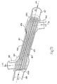
- Figure 1 shows a three-dimensional view of a first embodiment of an HME in accordance with the present invention
- Figure 2 shows a first section A-A of the first embodiment of the HME in Figure 1 ;
- Figure 3 shows a second section B-B of the HME in Figures 1, 2 ;
- FIG 4 shows an enlarged view of a septum (or filter) employed in the HME in Figures 1, 2 , 3 ;
- Figure 5 shows a three-dimensional view of a second embodiment of an HME in accordance with the present invention.
- Figure 6 shows a spread-out sheet from which to make an alternative septum (or filter) for an HME as shown in Figures 1, 2 , 3, 4 , 5 ;
- Figure 7 shows a first three-dimensional view of the Figure 6 sheet partly folded
- Figure 8 shows a second three-dimensional view of the Figure 6 sheet partly folded
- Figure 9 shows a three-dimensional view of a third embodiment of an HME in accordance with the present invention.
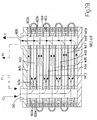
- Figure 10 shows a longitudinal section C-C of the HME in Figure 9 ;
- FIG 11 shows a septum (or filter) employed in the HME in Figures 9 and 10 ;
- Figure 12 shows a longitudinal section of the Figure 11 septum (or filter);
- Figure 13 shows a longitudinal section of a fourth embodiment of an HME in accordance with the present invention.
- Figure 14 shows a three-dimensional view of a fifth embodiment of an HME in accordance with the present invention.
- Figure 15 shows an exploded view of the Figure 14 exchanger
- Figure 16 shows a sheet from which to make a septum (or filter) for an HME as shown in Figure 14 ;
- Figure 17 shows a three-dimensional view of a sixth embodiment of an HME in accordance with the present invention.
- Figure 18 shows a septum (or filter) employed in the HME in Figure 17 ;
- Figure 19 shows a cross section E-E of the Figure 18 septum (or filter);
- Figure 20 shows (with enlarged details) a sheet from which to make a septum (or filter) as shown in Figures 17, 18 , 19 .
- FIGS 1, 2 , 3, 4 show a first embodiment of an exchanger (HME) 10 in accordance with the present invention.
- exchanger 10 comprises a substantially tubular first connector 11 connected to a tracheal tube (not shown) of a patient (not shown).
- Exchanger 10 also houses a substantially tubular second connector 12, along which flows inhaled gas produced by a ventilator (not shown) and indicated by arrow F1.
- Exchanger 10 also comprises a substantially tubular third connector 13, along which exhaled gas F2 is fed back to the ventilator.
- exchanger 10 comprises a substantially parallelepiped-shaped main body 14 interposed between first connector 11, on one side, and connectors 12, 13, on the other.
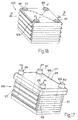
- Main body 14 houses a septum (or filter) 15, by which heat and moisture is exchanged between the outflow gas and inflow gas.
- septum (or filter) 15 is in the form of a pack, and is formed by pleating a sheet 150 of material capable of retaining and releasing heat and moisture (e.g. hygroscopic paper).
- the substantially parallelepiped-shaped pack so formed is potted (sealed) on part of its lateral walls 15a, 15b, and on the whole of a first end wall 15c ( Figure 4 ).
- the potting coat on first end wall 15c is not shown in Figure 4 .
- the inhaled gas from connector 12 is thus forced to flow through an exposed area A1 of lateral wall 15a and through a second end wall 15d, opposite first end wall 15c, to connector 11.
- the exhaled gas flows into septum (or filter) 15 through the non-potted second end wall 15d, is forced to flow through an exposed area A2 of lateral wall 15b, and is ultimately fed through connector 13 to the ventilator.
- septum (or filter) 15 obviously constitutes no patient dead space, which, in fact, in exchanger 10, is defined solely by the volume of connector 11.
- septum (or filter) 15 is formed by pleating sheet 150 to form a number of identical units 150a.
- “Fan-folding" units 150a one on top of the other produces a first set of passages 150b (each defined by two contiguous units 150a connected by a fold 150d) ( Figure 4 ) through which only the inhaled gas (arrow F1) flows; and a second set of passages 150c (each defined by two contiguous units 150a connected and hinged to each other by a fold 150d) ( Figure 4 ) through which only the exhaled gas (F2) flows.
- the gases are directed in known manner by two one-way valves (not shown) in the ventilator (not shown).
- the inhale valve When inhaling, the inhale valve is open and the exhale valve closed; conversely, when exhaling, the exhale valve is open and the inhale valve closed, so that the gases flow along whichever way is clear.
- septum (or filter) 15 which, as stated, may advantageously, though not necessarily, be made from a sheet 150 of hygroscopic paper.
- Exchanger 10 could also be made into an HME filter with practically no dead space, by applying a filtering membrane (not shown) inside connectors 12 and 13 or possibly over exposed areas A1 and A2.
- FIGs 5, 6 , 7, 8 show a second embodiment of a septum (or filter) 30 for insertion inside main body 14 of exchanger (HME) 10 (in lieu of septum (or filter) 15 described with reference to Figures 1-4 ).
- septum (or filter) 30 ( Figure 5 ) comprises a substantially rectangular sheet 31 divided into a number of units 31a of equal area. And each two contiguous units 31a are connected by a fold 31b which acts as a hinge.
- a continuous streak 32 of potting compound is deposited parallel to and along the whole length of a first long side 31c of sheet 31.
- a second long side 31d parallel to first side 31c
- short segments 33 of potting compound are deposited, each "astride" a respective fold 31b.
- a spot 34 of adhesive and sealing material e.g. potting compound, is deposited halfway between one fold 31b and another.
- the same potting compound as for continuous streak 32 is advantageously, though not necessarily, used for both segments 33 and spots 34.
- Continuous streak 32, segments 33, and spots 34 are deposited on both a first face FC1 ( Figure 7 ) and a second face FC2 ( Figure 8 ) of continuous sheet 31.
- the substantially parallelepiped-shaped septum (or filter) 30 so formed is potted (sealed) partly on its lateral walls 30c and 30d, and on the whole of its dorsal walls 30e, 30f, so that the inhaled gas from connector 12 ( Figure 2 ) is forced to flow through an exposed area A1 of lateral wall 30c, through septum (or filter) 30, and out through end wall 30b to connector 11 ( Figure 1 ).
- the exhaled gas flows into septum (or filter) 30 through second end wall 30b, is forced to flow through septum (or filter) 30 and an exposed area A2 of lateral wall 30d, and is ultimately fed to the ventilator through connector 13 ( Figure 1 ).
- Spots 34 combine to form a support to maintain correct spacing of the folds, so that the gases flow through the open gaps.
- Figures 9, 10 , 11, 12 show a third embodiment of the present invention.
- an HME 100 ( Figure 9 ) comprises four connectors 101, 102, 103, 104 located downstream from the patient-side Y connector (not shown); and a septum (or filter) 300 ( Figure 10 ) housed in use inside a central portion 100a of HME 100 ( Figure 9 ).
- this third embodiment may be said to be the starting point for the first ( Figures 1-4 ) and second ( Figures 5-8 ) embodiments.
- septum (or filter) 300 comprises two partly potted lateral walls 301a, 301b, and two fully potted dorsal walls 301c, 301d, all of which are potted using the same potting compound.
- the inhaled gas (F1) from the ventilator flows in through an exposed area A3 and out to the patient through an exposed area A4, and, as it flows through septum (or filter) 300, is heated and moistened by the gas (F2) exhaled in the preceding cycle (see below).
- the exhaled gas (F2) flows into septum (or filter) 300 through an exposed area A5 and out through an exposed area A6 to the ventilator.
- the exhaled gas obviously releases heat and moisture to the walls of a pleated sheet of the type illustrated in the previous embodiments.
- a casing 100b of HME 100 comprises four connectors 101, 102, 103, 104 - two for inhaled gas (101, 102) and two for exhaled gas (103, 104) - so that the two gas flows indicated by arrows F1, F2 in Figures 10 and 12 are separated.
- Casing 100b also comprises a depressed central section 100b* forming central portion 100a, so that septum (or filter) 300 is gripped between the walls of casing 100b to prevent gas (inhaled and exhaled) from flowing between the inner wall of central section 100b* and the outer wall of septum (or filter) 300.
- the gases (inhaled and exhaled) are forced to only flow through the desired exposed areas A3, A4 and A5, A6 respectively.
- the inhaled gas from the ventilator flows into septum (or filter) 300 through connector 101, and, by virtue of the potting compound on the central walls 301a, 301b, 301c, 301d, is forced to flow through area A3.
- septum (or filter) 300 is fitted with a respective binder 302a, 302b.
- the gas exhaled by the patient flows through connector 103, through area A5 into the passages between the exhale pleats, releases heat and moisture for the next inhale cycle, and flows through area A6 into connector 104, and from there to the ventilator.
- an important part is played by a first partition ED1, defined on one side by a wall 101a (of connector 101) and a wall 104a (of connector 104); and by a second partition ED2, defined on the other side by a wall 102a (of connector 102) and a wall 103a (of connector 103).
- Partitions ED1, ED2 rest against end walls 301e, 301f respectively, and provide for separating the inhaled gas (F1) from the exhaled gas (F2).
- Figure 13 shows a fourth embodiment of the present invention, which represents a different model from the ones described above, to channel and separate the two gas flows and so reduce dead space, and which basically is constructed in the same way as capillary filters used in haemodialysis (ion exchange between blood and dialysis liquid) and in cardiac surgery to oxygenate blood.
- Number 400 in Figure 13 indicates a fourth embodiment of an HME in accordance with the present invention, which comprises a substantially tubular body 401, in turn comprising a substantially tubular central portion 401a, and two end portions 401b, 401c swollen with respect to central portion 401a.
- Body 401 houses two perforated plates 402a, 402b, each housed in a respective end portion 401b, 401c, and which are substantially perpendicular to an axis (a) of substantial longitudinal symmetry of body 401, and are perforated to support a number of haemodialysis-type capillary tubes 403.
- the inhaled gas (arrow F1) from the ventilator flows through a connector 404 into end portion 401b, along central portion 401a into end portion 401c, and out to the patient through a connector 405.
- Each connector 404, 405 has a respective axis (b), (c) substantially perpendicular to axis (a).
- the inhaled gas (F1) flows inside the intercapillary space and sweeps capillary tubes 403, from which it absorbs heat and moisture released by the exhaled gas in the previous cycle (see below).
- the gas (F2) exhaled by the patient flows through a connector 406 and along the inside of capillary tubes 403, releases heat and moisture to the walls of capillary tubes 403 for the inhaled gas at the next inhale cycle, and ultimately flows out through a connector 407 to the ventilator (not shown).
- This provision aids in achieving laminar flow of the inhaled gas and, therefore, uniform heat and moisture exchange between the inhaled gas and the gas exhaled in the previous cycle.
- FIGs 14, 15 , 16 show a fifth embodiment of an HME 500, which employs a septum (or filter) 501 substantially formed from a sheet 502 ( Figure 16 ) of paper (or film) stamped to form a sort of plate-type exchanger (see below).
- a septum (or filter) 501 substantially formed from a sheet 502 ( Figure 16 ) of paper (or film) stamped to form a sort of plate-type exchanger (see below).
- sheet 502 ( Figure 16 ) forms two sets of inhale openings 503, 504 (arrow F1), and two sets of exhale openings 505, 506 (arrow F2) ( Figure 15 ).
- openings 503 are offset with respect to openings 504; and similarly, as regards the exhaled gas (F2), openings 505 are offset with respect to openings 506, to make the best use of the available heat and moisture exchange surfaces.
- a respective rectangular sealing frame 507 is stamped on each unit 502a, 502b; and, as shown in detail in Figure 16 , a short side 507a of one unit, e.g. unit 502a, comprises, from left to right, a first half-opening AS1 facing a first face 502a* of the unit; a half-notch IT1* (for reasons explained in detail below); and a second half-opening AS2 facing a second face 502a**, opposite first face 502a*, of the unit.
- a short side 507b of rectangular unit 502a comprises, from right to left, a third half-opening AS3 facing first face 502a*; a half-notch IT2* (for reasons explained in detail below); and a fourth half-opening AS4 (shown by a dash line in Figure 16 ) facing second face 502a** opposite first face 502a*.
- Short side 507a of frame 507 of rectangular unit 502b comprises (from right to left) a fifth half-opening AS5 facing first face 502a*; a half-notch IT1**; and a sixth half-opening AS6 facing second face 502a**.
- Short side 507b of frame 507 of rectangular unit 502b comprises (from left to right) a seventh half-opening AS7; a half-notch IT2**; and an eighth half-opening AS8 (shown by a dash line in Figure 16 ).
- each rectangular unit 502a, 502b has respective "herringbone" ribs 508, which, besides diverting flow to sweep a larger surface area, also act as spacers between adjacent units 502a, 502b folded one over the other in use.
- ribs 508 are advantageously equioriented, so that, in use, when sheet 502 is pleated, ribs 508 are superimposed and arranged crosswise to one another to improve gas circulation and make full use of the available heat and moisture exchange surface.
- half-openings AS1, AS2, AS3, AS4, AS5, AS6, AS7, AS8 are advantageously offset with respect to the relative side of frame 507 to correctly divert the gas flows (inhaled and exhaled).
- unit 502b is folded over unit 502a
- half-opening AS1 mates with half-opening AS5 to form one of openings 506, and half-opening AS3 mates with half-opening AS7 to form one of openings 505, so that openings 505 are offset with respect to openings 506; and
- half-notch IT1* mates with half-notch IT1** to form a complete notch IT1, as shown in Figure 15 .
- units 502a, 502b are hinged to each other by a hinge CN comprising the fold line and having no stamped material, so as to assist folding of sheet 502 of paper (or film) during the pleating operation.
- the two specular units 502a, 502b are repeated along the whole length of the paper (or film).
- second face 502a** is also stamped, but specularly with respect to first face 502a*, so that the result is the same as in Figures 1 and 2 , i.e. the inhaled gas (arrow F1) flows through a first number of passages, and the exhaled gas (arrow F2) through a second number of passages.
- the inhaled gas (arrow F1) flows through a first number of passages
- the exhaled gas (arrow F2) through a second number of passages.
- no potting is required, by virtue of stamped frames 507, which provide for both directing and sealing and separating the two gas flows.
- notches IT1, IT2 provide for attaching a top cover CP1 and a bottom cover CP2 respectively.
- Top cover CP1 comprises a substantially parallelepiped-shaped main body 509 open on one face.
- main body 509 comprises a tapered partition 510, the free end of which, in use, fits inside notch IT1.
- Partition 510 divides the space inside main body 509 into two identical portions 509a and 509b.
- a tubular connector 511 is integral with portion 509a
- a tubular connector 513 is integral with portion 509b ( Figure 15 ).
- bottom cover CP2 which has tubular connectors 512 and 514 ( Figure 14 ).
- the inhaled gas (F1) from the ventilator flows through connector 513 to HME 500, and into corresponding openings 503.
- both gas flows are diverted by ribs 508 to effectively sweep both face 502a* and face 502a**, through which heat and moisture exchange takes place.
- the incoming inhaled gas (F1) from connector 513 is directed to connector 514 located close to the corner opposite the inflow corner.
- Flow inside septum (or filter) 501 takes place with no gas leakage, by virtue of sealing frames 507.
- exhaled gas (F2) flows through connector 512 into exhale openings 505, and, as it flows through the system and is diverted by ribs 508, releases heat and moisture as it flows to connector 511 located close to the corner opposite the inflow corner, again with no leakage by virtue of sealing frames 507.
- FIGS 17, 18 , 19 , 20 show a sixth embodiment of the present invention, which relates to a system conceptually similar to the first embodiment ( Figures 1-4 ), second embodiment ( Figures 5-8 ), fourth embodiment ( Figure 13 ), and fifth embodiment ( Figures 14-16 ), and which also employs a stamped material, such as paper or film, capable of accumulating and releasing heat and moisture.
- a septum (or filter) 600 comprises a sheet 601 ( Figure 20 ), in turn comprising a number of substantially rectangular units 601a, 601b, 601c, 601d connected in twos by hinges CN1, CN2, CN3.
- a sealing frame 602 is stamped on each unit 601a, 601b, 601c, 601d, and, inside frame 602, sealing rings 603 are formed (stamped) about four through holes 604, 605, 606, 607 formed at the four corners of each unit 601a, 601b, 601c, 601d.
- two rings 603a, located at opposite corners, are characterized by a number of radial openings 603c ( Figure 20 - enlarged detail A), so that gas flows through a corresponding through hole 604, 605, 606, 607, as well as through openings 603c, which direct flow on the paper/film to sweep the inner surface of units 601a, 601b, 601c, 601d.
- the other two sealing rings 603b are solid, so that gas only flows through the corresponding through hole 604, 605, 606, 607, and not into the corresponding gaps INT between units 601a, 601b, 601c, 601d.
- Figure 19 shows clearly how units 601a, 601b, 601c, 601d are stacked, with sealing rings 603a alternating with sealing rings 603b.
- sheet 601 (of paper/film) is stamped on both faces, and a front face FC1 is specular with respect to a rear face FC2.
- Through holes 604, 605, 606, 608 formed in units 601a, 601b, 601c, 601d form four channels 608, 609, 610, 611, as shown in Figures 18 and 19 (only channels 609 and 610 are shown in Figure 19 ).
- the inhaled gas flows inside gaps INT1, INT3, INT5, INT7, INT9, and the exhaled gas inside gaps INT2, INT4, INT6, INT8 ( Figure 19 ).
- respective "herringbone” ribs 612 may be provided, which, besides diverting flow to sweep a larger surface area, also act as spacers between adjacent units 601a, 601b, 601c, 601d folded, in use, one on top of the other.
- ribs 612 are advantageously, though not necessarily, equioriented, so that, in use, when sheet 601 is pleated, ribs 612 are superimposed and arranged crosswise to one another to improve gas circulation and make full use of the available heat and moisture exchange surface.
- ribs 613 may be provided on, and extending the whole length of, the long sides 602a of frame 602. When the sheet is pleated, each rib 613 engages a corresponding seat 614 on the next unit 601a, 601b, 601c, 601d to position units 601a, 601b, 601c, 601d correctly when assembling septum (or filter) 600.
- Septum (or filter) 600 is also fitted with a cover CP ( Figure 17 ) comprising a substantially parallelepiped-shaped body 615 matching the perimeter of units 601a, 601b, 601c, 601d; and four connectors 616, 617, 618, 619 corresponding with respective channels 608, 609, 610, 611.
- the inhaled gas (F1) from the ventilator flows through connector 616 into septum (or filter) 600, along channel 608, through gaps INT1, INT3, INT5, INT7, INT9, and out through channel 609 and corresponding connector 617.
- the inhaled gas (F1) is enriched with heat and moisture accumulated in the previous exhale cycle and made available by virtue of the characteristics of septum (or filter) 600.
- the exhaled gas (F2) flows through connector 618 into septum (or filter) 600, along channel 610 into gaps INT2, INT2, INT6, INT8, releases heat and moisture to sheet 601 as it flows through, and flows back to the ventilator through channel 611 and corresponding connector 619.
- the main advantage of the present invention lies in reducing the dead space inside the ventilation circuit, by reducing the dead space of the HME.
- Dead space is clinically undesirable, by causing stagnation and mixing of the gases inhaled and exhaled by the patient; so much so that this volume is taken into account and compensated for in the ventilation setting.
- the advantage afforded by the invention also increases proportionally in the case of a newborn patient, in which the ventilation gas flow rate and volumes involved make the presence of a stagnant volume of ventilation gas a serious issue.
Landscapes
- Health & Medical Sciences (AREA)
- General Health & Medical Sciences (AREA)
- Pulmonology (AREA)
- Animal Behavior & Ethology (AREA)
- Anesthesiology (AREA)
- Biomedical Technology (AREA)
- Heart & Thoracic Surgery (AREA)
- Hematology (AREA)
- Life Sciences & Earth Sciences (AREA)
- Engineering & Computer Science (AREA)
- Emergency Medicine (AREA)
- Veterinary Medicine (AREA)
- Public Health (AREA)
- Measurement Of The Respiration, Hearing Ability, Form, And Blood Characteristics Of Living Organisms (AREA)
- External Artificial Organs (AREA)
- Drying Of Gases (AREA)
- Heat-Exchange Devices With Radiators And Conduit Assemblies (AREA)
- Materials For Medical Uses (AREA)
- Investigating Or Analysing Biological Materials (AREA)
- Thermotherapy And Cooling Therapy Devices (AREA)
Abstract

Description
- The present invention relates to a medical heat and moisture exchanger (HME).
- More specifically, the present invention may be used to advantage, though not exclusively, in anaesthesiology and intensive care, to which the following description refers purely by way of example.
- As is known, a heat and moisture exchanger (HME) is a device used in anaesthesiology and intensive care on intubated patients undergoing artificial ventilation.
- In such conditions, in fact, the patient's upper air passages being bypassed, and so not assisting in heating and moistening the cold, dry ventilation gas, an HME is inserted in the respiratory circuit, between the so-called "catheter mount" and "patient-side Y connector", to retain heat and moisture from the gas exhaled by the patient and heated and moistened by the lower air passages, and release large part of the retained heat and moisture to the air supply inhaled by the patient.
- Inserting an HME in the circuit, however, increases the "circuit dead space", on account of both the location and form of the HME, both of which factors assist in mixing the inhaled and exhaled gases.
- Dead space is formed on the side of each physiological (i.e. anatomical and alveolar) dead space, and possibly on the artificial respiratory system side, and constitutes a volume of air taking no part in oxygen-carbon dioxide exchange, which only takes place in alveoli perfused with blood. The physiological dead space therefore obviously varies according to various factors, whereas the portion produced by the respiratory circuit is of an artificial nature and affected by different factors.
- Circuit dead space is clinically undesirable, by causing stagnation and mixing of the fresh gas supply to the patient and the gas exhaled by the patient; so much so that this volume is taken into account and compensated for in the ventilation setting.
- Moreover, in the case of a pediatric or newborn patient, the gas flow rate and volumes involved make the presence of a stagnant volume of ventilation gas a serious issue.
- Nevertheless, in prior-art devices, even the presence of an HME normally poses problems.
- It is therefore an object of the present invention to provide a medical HME designed to eliminate the aforementioned drawbacks, and which at the same time is cheap and easy to produce.
- According to the present invention, there is provided a medical HME as claimed in the accompanying Claims.
- The HME according to the present invention operates on the principle of eliminating (ideally all) the dead space typically associated with its presence in the respiratory circuit.
- The HME according to the present invention is particularly suitable for use in anaesthesiology and intensive care, to passively heat and moisten respiratory gas supply to the patient.
- More specifically, the present invention proposes to eliminate the dead space typically associated with an HME located in respiratory circuits, downstream (in the ventilator-patient direction) from the Y connector.
- The HME according to the invention comprises, inside, a heat and moisture exchange septum (or filter), which is only swept on one side by the exhaled gas to accumulate heat and moisture.
- To the incoming, normally cold, dry inhaled gas, the septum (or filter), which is only swept on the other side by the exhaled gas, releases the accumulated heat and moisture to administer adequately heated, moistened gas to the patient.
- Operation as described above is achieved by separating the paths of the two (respectively, inhaled and exhaled) gases on the opposite surfaces of the septum (or filter). In fact, where there is no volume traversed in both respiratory flow directions, there is no dead space.
- A number of non-limiting embodiments of the present invention will be described by way of example with reference to the accompanying drawings, in which:
-
Figure 1 shows a three-dimensional view of a first embodiment of an HME in accordance with the present invention; -
Figure 2 shows a first section A-A of the first embodiment of the HME inFigure 1 ; -
Figure 3 shows a second section B-B of the HME inFigures 1, 2 ; -
Figure 4 shows an enlarged view of a septum (or filter) employed in the HME inFigures 1, 2 ,3 ; -
Figure 5 shows a three-dimensional view of a second embodiment of an HME in accordance with the present invention; -
Figure 6 shows a spread-out sheet from which to make an alternative septum (or filter) for an HME as shown inFigures 1, 2 ,3, 4 ,5 ; -
Figure 7 shows a first three-dimensional view of theFigure 6 sheet partly folded; -
Figure 8 shows a second three-dimensional view of theFigure 6 sheet partly folded; -
Figure 9 shows a three-dimensional view of a third embodiment of an HME in accordance with the present invention; -
Figure 10 shows a longitudinal section C-C of the HME inFigure 9 ; -
Figure 11 shows a septum (or filter) employed in the HME inFigures 9 and 10 ; -
Figure 12 shows a longitudinal section of theFigure 11 septum (or filter); -
Figure 13 shows a longitudinal section of a fourth embodiment of an HME in accordance with the present invention; -
Figure 14 shows a three-dimensional view of a fifth embodiment of an HME in accordance with the present invention; -
Figure 15 shows an exploded view of theFigure 14 exchanger; -
Figure 16 shows a sheet from which to make a septum (or filter) for an HME as shown inFigure 14 ; -
Figure 17 shows a three-dimensional view of a sixth embodiment of an HME in accordance with the present invention; -
Figure 18 shows a septum (or filter) employed in the HME inFigure 17 ; -
Figure 19 shows a cross section E-E of theFigure 18 septum (or filter); -
Figure 20 shows (with enlarged details) a sheet from which to make a septum (or filter) as shown inFigures 17, 18 ,19 . -
Figures 1, 2 ,3, 4 show a first embodiment of an exchanger (HME) 10 in accordance with the present invention. - In the first embodiment,
exchanger 10 comprises a substantially tubularfirst connector 11 connected to a tracheal tube (not shown) of a patient (not shown). -
Exchanger 10 also houses a substantially tubularsecond connector 12, along which flows inhaled gas produced by a ventilator (not shown) and indicated by arrow F1. -
Exchanger 10 also comprises a substantially tubularthird connector 13, along which exhaled gas F2 is fed back to the ventilator. - Finally,
exchanger 10 comprises a substantially parallelepiped-shapedmain body 14 interposed betweenfirst connector 11, on one side, andconnectors -
Main body 14 houses a septum (or filter) 15, by which heat and moisture is exchanged between the outflow gas and inflow gas. As shown in detail inFigure 4 , septum (or filter) 15 is in the form of a pack, and is formed by pleating asheet 150 of material capable of retaining and releasing heat and moisture (e.g. hygroscopic paper). - The substantially parallelepiped-shaped pack so formed is potted (sealed) on part of its
lateral walls first end wall 15c (Figure 4 ). For the sake of clarity, the potting coat onfirst end wall 15c is not shown inFigure 4 . - The inhaled gas from
connector 12 is thus forced to flow through an exposed area A1 oflateral wall 15a and through asecond end wall 15d, oppositefirst end wall 15c, toconnector 11. - Alternately, the exhaled gas flows into septum (or filter) 15 through the non-potted
second end wall 15d, is forced to flow through an exposed area A2 oflateral wall 15b, and is ultimately fed throughconnector 13 to the ventilator. - In this first embodiment, septum (or filter) 15 obviously constitutes no patient dead space, which, in fact, in
exchanger 10, is defined solely by the volume ofconnector 11. - As shown in detail in
Figure 4 , septum (or filter) 15 is formed bypleating sheet 150 to form a number ofidentical units 150a. - "Fan-folding"
units 150a one on top of the other produces a first set ofpassages 150b (each defined by twocontiguous units 150a connected by afold 150d) (Figure 4 ) through which only the inhaled gas (arrow F1) flows; and a second set ofpassages 150c (each defined by twocontiguous units 150a connected and hinged to each other by afold 150d) (Figure 4 ) through which only the exhaled gas (F2) flows. - The gases are directed in known manner by two one-way valves (not shown) in the ventilator (not shown). When inhaling, the inhale valve is open and the exhale valve closed; conversely, when exhaling, the exhale valve is open and the inhale valve closed, so that the gases flow along whichever way is clear.
- The two gases - inhaled (arrow F1) and exhaled (arrow F2) - therefore never come into direct contact with each other, and simply exchange heat and moisture via septum (or filter) 15, which, as stated, may advantageously, though not necessarily, be made from a
sheet 150 of hygroscopic paper. -
Exchanger 10 could also be made into an HME filter with practically no dead space, by applying a filtering membrane (not shown) insideconnectors -
Figures 5, 6 ,7, 8 show a second embodiment of a septum (or filter) 30 for insertion insidemain body 14 of exchanger (HME) 10 (in lieu of septum (or filter) 15 described with reference toFigures 1-4 ). - As shown in
Figure 6 , septum (or filter) 30 (Figure 5 ) comprises a substantiallyrectangular sheet 31 divided into a number ofunits 31a of equal area. And each twocontiguous units 31a are connected by afold 31b which acts as a hinge. - A
continuous streak 32 of potting compound is deposited parallel to and along the whole length of a firstlong side 31c ofsheet 31. Along a secondlong side 31d (parallel tofirst side 31c), on the other hand,short segments 33 of potting compound are deposited, each "astride" arespective fold 31b. - As shown in
Figure 6 , aspot 34 of adhesive and sealing material, e.g. potting compound, is deposited halfway between onefold 31b and another. The same potting compound as forcontinuous streak 32 is advantageously, though not necessarily, used for bothsegments 33 and spots 34. -
Continuous streak 32,segments 33, and spots 34 are deposited on both a first face FC1 (Figure 7 ) and a second face FC2 (Figure 8 ) ofcontinuous sheet 31. - When
sheet 31 is pleated atfolds 31b, folds 31b are sealed completely alongside 31c, coated withcontinuous streak 32 of potting compound, to form afirst end wall 30a (Figure 5 ); whereas, alongside 31d, only the tips offolds 31b are sealed, and the mid-portion of eachunit 31a (by spots 34), to form asecond end wall 30b (Figure 5 ). - As shown in
Figure 5 , in this case too, the substantially parallelepiped-shaped septum (or filter) 30 so formed is potted (sealed) partly on itslateral walls dorsal walls Figure 2 ) is forced to flow through an exposed area A1 oflateral wall 30c, through septum (or filter) 30, and out throughend wall 30b to connector 11 (Figure 1 ). - Alternately, the exhaled gas flows into septum (or filter) 30 through
second end wall 30b, is forced to flow through septum (or filter) 30 and an exposed area A2 oflateral wall 30d, and is ultimately fed to the ventilator through connector 13 (Figure 1 ). -
Spots 34 combine to form a support to maintain correct spacing of the folds, so that the gases flow through the open gaps. -
Figures 9, 10 ,11, 12 show a third embodiment of the present invention. - In the third embodiment, an HME 100 (
Figure 9 ) comprises fourconnectors Figure 10 ) housed in use inside acentral portion 100a of HME 100 (Figure 9 ). In a sense, this third embodiment may be said to be the starting point for the first (Figures 1-4 ) and second (Figures 5-8 ) embodiments. - As shown in
Figure 11 , septum (or filter) 300 comprises two partly pottedlateral walls dorsal walls Figure 12 , the inhaled gas (F1) from the ventilator flows in through an exposed area A3 and out to the patient through an exposed area A4, and, as it flows through septum (or filter) 300, is heated and moistened by the gas (F2) exhaled in the preceding cycle (see below). - Similarly, the exhaled gas (F2) flows into septum (or filter) 300 through an exposed area A5 and out through an exposed area A6 to the ventilator. As it flows through septum (or filter) 300, the exhaled gas obviously releases heat and moisture to the walls of a pleated sheet of the type illustrated in the previous embodiments.
- A
casing 100b ofHME 100, as stated, comprises fourconnectors Figures 10 and12 are separated.Casing 100b also comprises a depressedcentral section 100b* formingcentral portion 100a, so that septum (or filter) 300 is gripped between the walls ofcasing 100b to prevent gas (inhaled and exhaled) from flowing between the inner wall ofcentral section 100b* and the outer wall of septum (or filter) 300. As a result, the gases (inhaled and exhaled) are forced to only flow through the desired exposed areas A3, A4 and A5, A6 respectively. - In actual use, the inhaled gas from the ventilator flows into septum (or filter) 300 through
connector 101, and, by virtue of the potting compound on thecentral walls respective binder connector 102 to the patient (not shown). - The gas exhaled by the patient flows through
connector 103, through area A5 into the passages between the exhale pleats, releases heat and moisture for the next inhale cycle, and flows through area A6 intoconnector 104, and from there to the ventilator. - In this third embodiment, an important part is played by a first partition ED1, defined on one side by a
wall 101a (of connector 101) and a wall 104a (of connector 104); and by a second partition ED2, defined on the other side by awall 102a (of connector 102) and awall 103a (of connector 103). Partitions ED1, ED2 rest againstend walls 301e, 301f respectively, and provide for separating the inhaled gas (F1) from the exhaled gas (F2). -
Figure 13 shows a fourth embodiment of the present invention, which represents a different model from the ones described above, to channel and separate the two gas flows and so reduce dead space, and which basically is constructed in the same way as capillary filters used in haemodialysis (ion exchange between blood and dialysis liquid) and in cardiac surgery to oxygenate blood. - In this embodiment, the gas flows are separated using a number of capillary tubes with given heat and moisture retaining and release properties for a first gas flow; directing a second gas flow outside the capillary tubes; and accordingly locating the connectors to direct the gas flows.
Number 400 inFigure 13 indicates a fourth embodiment of an HME in accordance with the present invention, which comprises a substantiallytubular body 401, in turn comprising a substantially tubularcentral portion 401a, and twoend portions central portion 401a.Body 401 houses twoperforated plates respective end portion body 401, and are perforated to support a number of haemodialysis-type capillary tubes 403. - In this fourth embodiment, the inhaled gas (arrow F1) from the ventilator flows through a
connector 404 intoend portion 401b, alongcentral portion 401a intoend portion 401c, and out to the patient through aconnector 405. Eachconnector capillary tubes 403, from which it absorbs heat and moisture released by the exhaled gas in the previous cycle (see below). - The gas (F2) exhaled by the patient, in turn, flows through a
connector 406 and along the inside ofcapillary tubes 403, releases heat and moisture to the walls ofcapillary tubes 403 for the inhaled gas at the next inhale cycle, and ultimately flows out through aconnector 407 to the ventilator (not shown). - In the
Figure 13 solution too, mixing of the two inhaled and exhaled gas flows is prevented byplates central portion 401a,capillary tubes 403 are preferably closer together to reduce the area of the intercapillary space. - This provision aids in achieving laminar flow of the inhaled gas and, therefore, uniform heat and moisture exchange between the inhaled gas and the gas exhaled in the previous cycle.
-
Figures 14, 15 ,16 show a fifth embodiment of anHME 500, which employs a septum (or filter) 501 substantially formed from a sheet 502 (Figure 16 ) of paper (or film) stamped to form a sort of plate-type exchanger (see below). - Once stamped and pleated, sheet 502 (
Figure 16 ) forms two sets ofinhale openings 503, 504 (arrow F1), and two sets ofexhale openings 505, 506 (arrow F2) (Figure 15 ). - As regards the inhaled gas (F1),
openings 503 are offset with respect toopenings 504; and similarly, as regards the exhaled gas (F2),openings 505 are offset with respect toopenings 506, to make the best use of the available heat and moisture exchange surfaces. - With reference to two adjacent, substantially
rectangular units rectangular sealing frame 507 is stamped on eachunit Figure 16 , ashort side 507a of one unit,e.g. unit 502a, comprises, from left to right, a first half-opening AS1 facing afirst face 502a* of the unit; a half-notch IT1* (for reasons explained in detail below); and a second half-opening AS2 facing asecond face 502a**, oppositefirst face 502a*, of the unit. - Similarly, a
short side 507b ofrectangular unit 502a comprises, from right to left, a third half-opening AS3 facingfirst face 502a*; a half-notch IT2* (for reasons explained in detail below); and a fourth half-opening AS4 (shown by a dash line inFigure 16 ) facingsecond face 502a** oppositefirst face 502a*. The same also applies torectangular unit 502b adjacent torectangular unit 502a.Short side 507a offrame 507 ofrectangular unit 502b (likeunit 502a) comprises (from right to left) a fifth half-opening AS5 facingfirst face 502a*; a half-notch IT1**; and a sixth half-opening AS6 facingsecond face 502a**. -
Short side 507b offrame 507 ofrectangular unit 502b comprises (from left to right) a seventh half-opening AS7; a half-notch IT2**; and an eighth half-opening AS8 (shown by a dash line inFigure 16 ). As shown inFigure 16 , eachrectangular unit ribs 508, which, besides diverting flow to sweep a larger surface area, also act as spacers betweenadjacent units ribs 508 are advantageously equioriented, so that, in use, whensheet 502 is pleated,ribs 508 are superimposed and arranged crosswise to one another to improve gas circulation and make full use of the available heat and moisture exchange surface. - Moreover, half-openings AS1, AS2, AS3, AS4, AS5, AS6, AS7, AS8 are advantageously offset with respect to the relative side of
frame 507 to correctly divert the gas flows (inhaled and exhaled). Whenunit 502b is folded overunit 502a, half-opening AS1 mates with half-opening AS5 to form one ofopenings 506, and half-opening AS3 mates with half-opening AS7 to form one ofopenings 505, so thatopenings 505 are offset with respect toopenings 506; and half-notch IT1* mates with half-notch IT1** to form a complete notch IT1, as shown inFigure 15 . - As shown in
Figure 16 ,units sheet 502 of paper (or film) during the pleating operation. The twospecular units - With reference, for example, to
unit 502a,second face 502a** is also stamped, but specularly with respect tofirst face 502a*, so that the result is the same as inFigures 1 and 2 , i.e. the inhaled gas (arrow F1) flows through a first number of passages, and the exhaled gas (arrow F2) through a second number of passages. In this case, no potting is required, by virtue of stampedframes 507, which provide for both directing and sealing and separating the two gas flows. Moreover, notches IT1, IT2 provide for attaching a top cover CP1 and a bottom cover CP2 respectively. Top cover CP1 comprises a substantially parallelepiped-shapedmain body 509 open on one face. - Inside,
main body 509 comprises a taperedpartition 510, the free end of which, in use, fits inside notch IT1.Partition 510 divides the space insidemain body 509 into twoidentical portions tubular connector 511 is integral withportion 509a, and atubular connector 513 is integral withportion 509b (Figure 15 ). The same also applies to bottom cover CP2, which hastubular connectors 512 and 514 (Figure 14 ). - To sum up, the inhaled gas (F1) from the ventilator flows through
connector 513 toHME 500, and into correspondingopenings 503. - As they flow through the system, both gas flows (inhaled and exhaled) are diverted by
ribs 508 to effectively sweep both face 502a* and face 502a**, through which heat and moisture exchange takes place. The same obviously also applies tounit 502b and all the other units forming part of septum (or filter) 501. The incoming inhaled gas (F1) fromconnector 513 is directed toconnector 514 located close to the corner opposite the inflow corner. Flow inside septum (or filter) 501 takes place with no gas leakage, by virtue of sealing frames 507. - Similarly, the exhaled gas (F2) flows through
connector 512 intoexhale openings 505, and, as it flows through the system and is diverted byribs 508, releases heat and moisture as it flows toconnector 511 located close to the corner opposite the inflow corner, again with no leakage by virtue of sealing frames 507. -
Figures 17, 18 ,19 ,20 show a sixth embodiment of the present invention, which relates to a system conceptually similar to the first embodiment (Figures 1-4 ), second embodiment (Figures 5-8 ), fourth embodiment (Figure 13 ), and fifth embodiment (Figures 14-16 ), and which also employs a stamped material, such as paper or film, capable of accumulating and releasing heat and moisture. A septum (or filter) 600 comprises a sheet 601 (Figure 20 ), in turn comprising a number of substantiallyrectangular units - A sealing
frame 602 is stamped on eachunit frame 602, sealing rings 603 are formed (stamped) about four throughholes unit rings 603a, located at opposite corners, are characterized by a number ofradial openings 603c (Figure 20 - enlarged detail A), so that gas flows through a corresponding throughhole openings 603c, which direct flow on the paper/film to sweep the inner surface ofunits - The other two sealing
rings 603b, on the other hand, are solid, so that gas only flows through the corresponding throughhole units Figure 19 shows clearly howunits rings 603a alternating with sealingrings 603b. In other words, sheet 601 (of paper/film) is stamped on both faces, and a front face FC1 is specular with respect to a rear face FC2. Throughholes units channels Figures 18 and19 (onlychannels Figure 19 ). As a result, the inhaled gas flows inside gaps INT1, INT3, INT5, INT7, INT9, and the exhaled gas inside gaps INT2, INT4, INT6, INT8 (Figure 19 ). - As before, respective "herringbone"
ribs 612 may be provided, which, besides diverting flow to sweep a larger surface area, also act as spacers betweenadjacent units - As opposed to being specular,
ribs 612 are advantageously, though not necessarily, equioriented, so that, in use, whensheet 601 is pleated,ribs 612 are superimposed and arranged crosswise to one another to improve gas circulation and make full use of the available heat and moisture exchange surface. -
Further ribs 613 may be provided on, and extending the whole length of, thelong sides 602a offrame 602. When the sheet is pleated, eachrib 613 engages acorresponding seat 614 on thenext unit units - Septum (or filter) 600 is also fitted with a cover CP (
Figure 17 ) comprising a substantially parallelepiped-shapedbody 615 matching the perimeter ofunits connectors respective channels - To sum up, the inhaled gas (F1) from the ventilator flows through connector 616 into septum (or filter) 600, along
channel 608, through gaps INT1, INT3, INT5, INT7, INT9, and out throughchannel 609 andcorresponding connector 617. - Inside gaps INT1, INT3, INT5, INT7, INT9, the inhaled gas (F1) is enriched with heat and moisture accumulated in the previous exhale cycle and made available by virtue of the characteristics of septum (or filter) 600.
- Similarly, the exhaled gas (F2) flows through connector 618 into septum (or filter) 600, along
channel 610 into gaps INT2, INT2, INT6, INT8, releases heat and moisture tosheet 601 as it flows through, and flows back to the ventilator throughchannel 611 andcorresponding connector 619. - The main advantage of the present invention lies in reducing the dead space inside the ventilation circuit, by reducing the dead space of the HME. Dead space is clinically undesirable, by causing stagnation and mixing of the gases inhaled and exhaled by the patient; so much so that this volume is taken into account and compensated for in the ventilation setting. The advantage afforded by the invention also increases proportionally in the case of a newborn patient, in which the ventilation gas flow rate and volumes involved make the presence of a stagnant volume of ventilation gas a serious issue.
Claims (40)
- An HME having a device of a material capable of absorbing, retaining, and releasing heat and/or moisture of exhaled and inhaled gas, said device having separate channels for inhaled and exhaled gas to avoid mixture of said gases.
- An HME (heat and moisture exchanger) (10) comprising a septum (or filter) (15) formed by pleating a sheet (150) of material capable of retaining and releasing heat and moisture; wherein walls (15a, 15b, 15c) of said septum (or filter) (15) are coated partly or completely with sealing material to define at least two exposed areas (A1, A2) through which inhaled gas (F1) and exhaled gas (F2) flow respectively; and wherein each sheet (150) of material is divided into identical units (150a) "fan-folded", in use, one on top of another to form a first set of passages (150b) through which only the inhaled gas (F1) flows, and a second set of passages (150c) through which only the exhaled gas (F2) flows.
- An HME (10) as claimed in Claim 2, wherein said material capable of retaining and releasing heat and moisture is hygroscopic paper.
- An HME (10) as claimed in either of the foregoing Claims, wherein said sealing material is a potting compound.
- An HME (10) as claimed in Claim 2, and comprising a substantially parallelepiped-shaped main body (14) for housing said septum (or filter) (15); and three tubular connectors (11, 12, 13) integral with said main body (14).
- An HME (10) as claimed in Claims 2 and 5, wherein a filtering membrane is applied to the connectors (12, 13) or to the exposed areas (A1, A2).
- An HME (10) as claimed in Claim 2, and comprising a septum (or filter) (30), in turn comprising a substantially rectangular sheet (31) divided into a number of units (31a) of equal area, each two contiguous areas (31a) being connected to each other by a fold (31b) which acts as a hinge; wherein a continuous streak (32) of adhesive and sealing material is deposited parallel to a first long side (31c) of the sheet and along the whole length of the first long side (31c); and wherein segments (33) of adhesive and sealing material are deposited along a second long side (31d), parallel to the first long side (31c), of the sheet; each of said segments (33) extending astride a respective fold (31b) between two units (31a).
- An HME (10) as claimed in Claim 7, wherein a spot (34) of adhesive and sealing material is deposited halfway between one fold (31b) and another.
- An HME (10) as claimed in Claim 8, wherein the continuous streak (32), the segments (33), and the spots (34) are deposited on both a first face (FC1) of the sheet (31) and a second face (FC2) of said sheet.
- An HME (10) as claimed in Claim 9, wherein lateral walls (30c, 30d) and dorsal walls (30e, 30f) of said septum (or filter) (30) are coated partly or completely with sealing material to define at least two exposed areas (A1, A2) through which inhaled gas (F1) and exhaled gas (F2) flow respectively.
- An HME (100) comprising a casing (100b) to which two first connectors (101, 102) for inhaled gas (F1) and two second connectors (103, 104) for exhaled gas (F2) are connected; said casing (100b) comprising a central section (100b*) for gripping a septum (or filter) (300); and said septum (or filter) (300) comprising two lateral walls (301a, 301b) coated partly, and two dorsal walls (301c, 301d) coated completely, with sealing material.
- An HME (100) as claimed in Claim 11, and comprising a first partition (ED1) on one side, and a second partition (ED2) on the other side.
- An HME (100) as claimed in Claim 12, wherein said first partition (ED1) is defined by the wall (101a) of a said first connector (101) and the wall (104a) of a said second connector (104) on one side; and the second partition (ED2) is defined by the wall (102a) of a said first connector (102) and the wall (103a) of a said second connector (103) on the other side.
- An HME (100) as claimed in Claim 13, wherein, in use, said first partition (ED1) rests against a first end wall (301e) of the septum (or filter) (300), and said second partition rests against a second end wall (301f) of the septum (or filter) (300), to separate flow of the inhaled gas (F1) from flow of the exhaled gas (F2).
- An HME (400) comprising a body (401), in turn comprising a substantially tubular central portion (401a), and two end portions (401b, 401c) swollen with respect to the central portion (401a); the body (401) housing two perforated plates (402a, 402b), each housed in a respective end portion (401b, 401c); and the two perforated plates (402a, 402b) supporting a number of capillary tubes (403) by which heat and moisture exchange takes place.
- An HME (400) as claimed in Claim 15, wherein the inhaled gas (F1) flows through a first connector (404) into one end portion (401b), flows along the central portion (401a) into the other end portion (401c), and flows out to a patient through a second connector (405); and the exhaled gas (F2) exhaled by the patient flows in through a third connector (406) and along the inside of the capillary tubes (403), and releases to the walls of said capillary tubes (403) heat and moisture for the inhaled gas (F1) at the next inhale cycle.
- An HME (400), wherein the first and second connector (404, 405) each have a respective axis of substantially longitudinal symmetry (b), (c) substantially perpendicular to an axis of substantially longitudinal symmetry (a) of the body (401).
- An HME (400) as claimed in any one of Claims 15, 16, 17 wherein the capillary tubes (403) are closer together inside the central portion (401a) to reduce the area of the intercapillary space, so that flow of the inhaled gas is substantially laminar.
- An HME (500) comprising a septum (or filter) (501) formed substantially from a stamped, pleated sheet (502).
- An HME (500) as claimed in Claim 19, and comprising a number of substantially rectangular units (502a, 502b) of equal area; each unit (502a, 502b) having a respective stamped rectangular sealing frame (507) comprising half-openings (AS1, AS2, AS3, AS4; AS5, AS6, AS7, AS8).
- An HME (500) as claimed in Claim 20, wherein, when a first unit (502b) is folded onto a second unit (502a), a first half-opening (AS1) of the second unit mates with a first half-opening (AS5) of the first unit to form a first opening (506), and a second half-opening (AS3) of the second unit mates with a second half-opening (AS7) of the first unit to form a second opening (505).
- An HME (500) as claimed in Claim 21, wherein the openings (504, 505) are offset with respect to the relative frame (507) to divert flow of the inhaled gas (F1) and exhaled gas (F2).
- An HME (500) as claimed in Claim 20, wherein said frame (507) of said second unit (502a) comprises a first half-notch (IT1*) at the top, and a second half-notch (IT2*) at the bottom, and said frame (507) of said first unit (502b) comprises a third half-notch (IT1**) at the top, and a fourth half-notch (IT2**) at the bottom; the first half-notch (IT1*) mating with the third half-notch (IT1**) to form a first complete notch (IT1), and the second half-notch (IT2*) mating with the fourth half-notch (IT2**) to form a second complete notch (IT2).
- An HME (500) as claimed in Claim 20, wherein each unit (502a) has a first face (502a*) having two half-openings (AS1, AS3) offset with respect to each other; and a second face (502a**) having two half-openings (AS4, AS4) offset with respect to each other; the first face (502a*) being stamped specularly with respect to the second face (502a**).
- An HME (500) as claimed in any one of Claims 20 to 24, wherein each unit (502a, 502b) has respective "herringbone" ribs (508), which are nonspecular but equioriented, so that they are superimposed and arranged crosswise to one another in use.
- An HME (500) as claimed in Claim 19, and comprising a top cover (CP1) and a bottom cover (CP2).
- An HME (500) as claimed in Claim 26, wherein each cover (CP1, CP2) comprises a substantially parallelepiped-shaped main body (509) open on one face; said main body (509) comprising an inner partition (510) separating the inhaled gas (F1) from the exhaled gas (F2).
- An HME (500) as claimed in Claims 23 and 27, wherein the partition (510) is tapered, so that its free end is housed, in use, inside a respective said complete notch (IT1; IT2).
- An HME (500) as claimed in Claim 27, wherein the main body (509) is divided by said partition (510) into a first and second portion (509a, 509b); a first tubular connector (511) being integral with the first portion (509a), and a second tubular connector (513) being integral with the second portion (509b).
- An HME comprising a septum (or filter) (600), in turn comprising a sheet (601) comprising a number of substantially rectangular units (601a, 601b, 601c, 601d) connected to one another in twos by hinges (CN1, CN2, CN3); a respective sealing frame (602) being stamped on each unit (601a, 601b, 601c, 601d); and, inside the sealing frame, two first sealing rings (603a) and two second sealing rings (603b) being formed about four through holes (604, 605, 606, 607) formed at the four corners of each unit (601a, 601b, 601c, 601d).
- An HME as claimed in Claim 30, and comprising, on each face, two first sealing rings (603a) characterized by a number of radial openings (603c).
- An HME as claimed in Claim 31, wherein, in use, the units (601a, 601b, 601c, 601d) are stacked, with the first sealing rings (603a) alternating with the second sealing rings (603b).
- An HME as claimed in Claim 30, wherein the through holes (604, 605, 606, 607) formed in the units (601a, 601b, 601c, 601d) combine to form four channels (608, 609, 610, 611).
- An HME as claimed in Claim 33, wherein the exhaled gas (F2) flows inside first gaps (INT1, INT3, INT5, INT7, INT9), and the inhaled gas (F1) flows inside second gaps (INT2, INT4, INT6, INT8).
- An HME as claimed in Claim 30, wherein each unit (601a, 601b, 601c, 601d) comprises respective "herringbone" ribs (612), which are nonspecular but equioriented, so that they are superimposed and arranged crosswise to one another in use.
- An HME as claimed in Claim 35, wherein each long side (602a) of the frame (602) of a first unit (601a, 601b, 601c, 601d) has a respective rib (613) which, in use, is housed inside a corresponding seat (614) on a contiguous second unit (601a, 601b, 601c, 601d).
- An HME as claimed in Claim 30, wherein the septum (or filter) (600) is fitted with a cover (CP) comprising a substantially parallelepiped-shaped body (615) which matches the perimeter of the units (601a, 601b, 601c, 601d); and four connectors (616, 617, 618, 619) corresponding with respective said channels (608, 609, 610, 611).
- A filter for use in an HME as claimed in either of the foregoing Claims 2-37.
- A septum for use in an HME as claimed in either of the foregoing Claims 2-37.
- A ventilating system for use in anaesthesiology and intensive care on intubated patients undergoing artificial ventilation, characterized in that it comprises at least one HME as claimed in either of the foregoing Claims.
Priority Applications (15)
| Application Number | Priority Date | Filing Date | Title |
|---|---|---|---|
| EP09168444A EP2113276B1 (en) | 2007-05-21 | 2007-05-21 | Medical heat and moisture exchanger (HME) |
| EP07425304A EP1994952B1 (en) | 2007-05-21 | 2007-05-21 | Medical heat and moisture exchanger (HME) |
| EP09168442A EP2113278B1 (en) | 2007-05-21 | 2007-05-21 | Medical heat and moisture exchanger (HME) |
| EP09168443A EP2113275B1 (en) | 2007-05-21 | 2007-05-21 | Medical heat and moisture exchanger (HME) |
| EP09168445A EP2113277B1 (en) | 2007-05-21 | 2007-05-21 | Medical heat and moisture exchanger (HME) |
| AT07425304T ATE516056T1 (en) | 2007-05-21 | 2007-05-21 | MEDICAL HEAT AND FLUID EXCHANGER |
| ES07425304T ES2367529T3 (en) | 2007-05-21 | 2007-05-21 | HEAT AND MOISTURE EXCHANGER ENGLISH HEALTH AND HUMIDITY MEDICAL EXCHANGER (HME). |
| CA2629165A CA2629165C (en) | 2007-05-21 | 2008-04-03 | Medical heat and moisture exchanger (hme) |
| ZA200803183A ZA200803183B (en) | 2007-05-21 | 2008-04-10 | Medical heat and moisture exchanger (HME) |
| AU2008201691A AU2008201691B2 (en) | 2007-05-21 | 2008-04-16 | Medical heat and moisture exchanger (HME) |
| MX2008004961A MX2008004961A (en) | 2007-05-21 | 2008-04-16 | Medical heat and moisture exchanger (hme). |
| US12/120,982 US20080283053A1 (en) | 2007-05-21 | 2008-05-15 | Medical heat and moisture exchanger (hme) |
| CN2008100980042A CN101310787B (en) | 2007-05-21 | 2008-05-20 | Medical heat and moisture exchanger (hme) |
| JP2008131586A JP2008284370A (en) | 2007-05-21 | 2008-05-20 | Medical heat and moisture exchanger (hme) |
| BRPI0801530A BRPI0801530A8 (en) | 2007-05-21 | 2008-05-21 | heat and moisture exchanger for medical use |
Applications Claiming Priority (1)
| Application Number | Priority Date | Filing Date | Title |
|---|---|---|---|
| EP07425304A EP1994952B1 (en) | 2007-05-21 | 2007-05-21 | Medical heat and moisture exchanger (HME) |
Related Child Applications (8)
| Application Number | Title | Priority Date | Filing Date |
|---|---|---|---|
| EP09168442A Division EP2113278B1 (en) | 2007-05-21 | 2007-05-21 | Medical heat and moisture exchanger (HME) |
| EP09168443A Division EP2113275B1 (en) | 2007-05-21 | 2007-05-21 | Medical heat and moisture exchanger (HME) |
| EP09168444A Division EP2113276B1 (en) | 2007-05-21 | 2007-05-21 | Medical heat and moisture exchanger (HME) |
| EP09168445A Division EP2113277B1 (en) | 2007-05-21 | 2007-05-21 | Medical heat and moisture exchanger (HME) |
| EP09168442.3 Division-Into | 2009-08-24 | ||
| EP09168445.6 Division-Into | 2009-08-24 | ||
| EP09168443.1 Division-Into | 2009-08-24 | ||
| EP09168444.9 Division-Into | 2009-08-24 |
Publications (2)
| Publication Number | Publication Date |
|---|---|
| EP1994952A1 true EP1994952A1 (en) | 2008-11-26 |
| EP1994952B1 EP1994952B1 (en) | 2011-07-13 |
Family
ID=38566907
Family Applications (5)
| Application Number | Title | Priority Date | Filing Date |
|---|---|---|---|
| EP09168443A Not-in-force EP2113275B1 (en) | 2007-05-21 | 2007-05-21 | Medical heat and moisture exchanger (HME) |
| EP09168442A Not-in-force EP2113278B1 (en) | 2007-05-21 | 2007-05-21 | Medical heat and moisture exchanger (HME) |
| EP07425304A Active EP1994952B1 (en) | 2007-05-21 | 2007-05-21 | Medical heat and moisture exchanger (HME) |
| EP09168444A Not-in-force EP2113276B1 (en) | 2007-05-21 | 2007-05-21 | Medical heat and moisture exchanger (HME) |
| EP09168445A Not-in-force EP2113277B1 (en) | 2007-05-21 | 2007-05-21 | Medical heat and moisture exchanger (HME) |
Family Applications Before (2)
| Application Number | Title | Priority Date | Filing Date |
|---|---|---|---|
| EP09168443A Not-in-force EP2113275B1 (en) | 2007-05-21 | 2007-05-21 | Medical heat and moisture exchanger (HME) |
| EP09168442A Not-in-force EP2113278B1 (en) | 2007-05-21 | 2007-05-21 | Medical heat and moisture exchanger (HME) |
Family Applications After (2)
| Application Number | Title | Priority Date | Filing Date |
|---|---|---|---|
| EP09168444A Not-in-force EP2113276B1 (en) | 2007-05-21 | 2007-05-21 | Medical heat and moisture exchanger (HME) |
| EP09168445A Not-in-force EP2113277B1 (en) | 2007-05-21 | 2007-05-21 | Medical heat and moisture exchanger (HME) |
Country Status (11)
| Country | Link |
|---|---|
| US (1) | US20080283053A1 (en) |
| EP (5) | EP2113275B1 (en) |
| JP (1) | JP2008284370A (en) |
| CN (1) | CN101310787B (en) |
| AT (1) | ATE516056T1 (en) |
| AU (1) | AU2008201691B2 (en) |
| BR (1) | BRPI0801530A8 (en) |
| CA (1) | CA2629165C (en) |
| ES (1) | ES2367529T3 (en) |
| MX (1) | MX2008004961A (en) |
| ZA (1) | ZA200803183B (en) |
Cited By (4)
| Publication number | Priority date | Publication date | Assignee | Title |
|---|---|---|---|---|
| ITTO20090200A1 (en) * | 2009-03-17 | 2010-09-18 | Covidien Ag | SYSTEM FOR CONDITIONING RESPIRATORY GASES |
| EP2647401A1 (en) * | 2012-04-04 | 2013-10-09 | Covidien AG | A filter of absorbing, retaining and releasing heat and/or moisture of exhaled and inhaled gas and method of forming such a filter |
| EP4101488A1 (en) * | 2011-11-11 | 2022-12-14 | ResMed Pty Ltd | Exchanger conduit |
| EP3528879B1 (en) * | 2016-10-18 | 2024-04-24 | Fisher & Paykel Healthcare Limited | Filter |
Families Citing this family (8)
| Publication number | Priority date | Publication date | Assignee | Title |
|---|---|---|---|---|
| US8839791B2 (en) | 2011-06-22 | 2014-09-23 | Breathe Technologies, Inc. | Ventilation mask with integrated piloted exhalation valve |
| US9038634B2 (en) | 2011-06-22 | 2015-05-26 | Breathe Technologies, Inc. | Ventilation mask with integrated piloted exhalation valve |
| US9616194B2 (en) | 2011-06-22 | 2017-04-11 | Breathe Technologies, Inc. | Ventilation mask with integrated piloted exhalation valve and method of ventilating a patient using the same |
| GB2496141B (en) * | 2011-11-01 | 2017-04-26 | Intersurgical Ag | Improvements relating to breathing systems |
| US9878121B2 (en) | 2013-03-13 | 2018-01-30 | Breathe Technologies, Inc. | Ventilation mask with heat and moisture exchange device |
| JP6640081B2 (en) | 2013-07-29 | 2020-02-05 | レスメド・プロプライエタリー・リミテッド | Heat-moisture exchanger for patient interface |
| WO2015052681A1 (en) | 2013-10-11 | 2015-04-16 | Fisher & Paykel Healthcare Limited | Hme and compact breathing apparatus |
| BR102021009290A2 (en) | 2021-05-13 | 2021-08-24 | Mla Suprimentos Medicos Ltda | heat and moisture exchanger filter with biocidal activity, method of preparation of heat and moisture exchanger filter with biocidal activity and use of silver nanoparticles |
Citations (6)
| Publication number | Priority date | Publication date | Assignee | Title |
|---|---|---|---|---|
| US5320096A (en) * | 1992-02-21 | 1994-06-14 | Gibeck Respiration Ab | Filtering device and the use thereof |
| WO1996035911A1 (en) * | 1995-05-11 | 1996-11-14 | Elastek, Inc. | Elastomer bed for heating and moisturizing respiratory gases |
| EP0861671A2 (en) * | 1997-02-28 | 1998-09-02 | Smiths Industries Public Limited Company | Gas treatment devices |
| WO2000002610A1 (en) * | 1998-07-10 | 2000-01-20 | Enternet Medical, Inc. | Apparatus for providing heat/moisture to respiratory gases |
| EP1208866A2 (en) * | 2000-11-23 | 2002-05-29 | Bellmafiok S.r.l. | Self-moistening tracheostomy device |
| US6397842B1 (en) * | 1998-06-09 | 2002-06-04 | Smiths Group Public Limited Company | Fluid-treatment devices |
Family Cites Families (36)
| Publication number | Priority date | Publication date | Assignee | Title |
|---|---|---|---|---|
| US2019351A (en) * | 1934-11-17 | 1935-10-29 | Gen Electric | Air conditioning apparatus |
| DE1169615B (en) * | 1954-08-27 | 1964-05-06 | Draegerwerk Ag | Device for artificial ventilation, inhalation, anesthesia, etc. |
| US4051898A (en) * | 1969-03-20 | 1977-10-04 | Mitsubishi Denki Kabushiki Kaisha | Static heat-and-moisture exchanger |
| US3692184A (en) * | 1970-10-07 | 1972-09-19 | Carborundum Co | Filter cartridge and pack therefor and method of making same |
| FR2236537B1 (en) * | 1973-07-11 | 1977-12-23 | Rhone Poulenc Ind | |
| US4040804A (en) * | 1975-05-23 | 1977-08-09 | Halm Instrument Co., Inc. | Heat and moisture exchanger |
| DE2529050C2 (en) * | 1975-06-30 | 1983-01-05 | Drägerwerk AG, 2400 Lübeck | Moisture exchanger in devices for breathing and anesthesia |
| DE2617985C3 (en) * | 1976-04-24 | 1979-02-22 | Draegerwerk Ag, 2400 Luebeck | Breathing air humidifiers for respiratory devices |
| DE2703892C2 (en) * | 1977-01-31 | 1982-09-23 | Drägerwerk AG, 2400 Lübeck | Breathing air humidifiers for respiratory devices |
| DE2929584A1 (en) * | 1979-07-21 | 1981-02-05 | Draegerwerk Ag | MOISTURE EXCHANGER IN BREATHING DEVICES |
| DE2929615C2 (en) * | 1979-07-21 | 1982-10-07 | Drägerwerk AG, 2400 Lübeck | Moisture exchangers in devices for breathing |
| JPS61280871A (en) * | 1985-06-06 | 1986-12-11 | テルモ株式会社 | Heating humidifier for respiration |
| GB8916361D0 (en) * | 1989-07-18 | 1989-09-06 | Smiths Industries Plc | Filters |
| SE503089C2 (en) * | 1991-09-20 | 1996-03-25 | Gibeck Respiration Ab | Apparatus for connecting a patient to a respirator comprising a humidifier heat exchanger and use of a humidifier for heat exchanger in this apparatus |
| US5339653A (en) * | 1992-10-29 | 1994-08-23 | Degregoria Anthony J | Elastomer bed |
| JPH1194476A (en) * | 1997-09-25 | 1999-04-09 | Konica Corp | Heat exchanger |
| US6171374B1 (en) * | 1998-05-29 | 2001-01-09 | Ballard Power Systems Inc. | Plate and frame fluid exchanging assembly with unitary plates and seals |
| US6330883B1 (en) * | 1999-02-17 | 2001-12-18 | Filtrona Richmond, Inc. | Heat and moisture exchanger comprising hydrophilic nylon and methods of using same |
| US6165241A (en) * | 1999-03-27 | 2000-12-26 | Aaf International, Inc. | Pleated filter media with strip spacers and method of making |
| IT1310042B1 (en) * | 1999-11-26 | 2002-02-05 | Pier Luigi Delvigo | FILTER WITHOUT DEAD SPACE |
| US6338383B1 (en) * | 1999-12-22 | 2002-01-15 | Visteon Global Technologies, Inc. | Heat exchanger and method of making same |
| IT1318430B1 (en) * | 2000-03-29 | 2003-08-25 | Mallinckrodt Holdings B V | DEVICE FOR PASSIVE HUMIDIFICATION OF TRACHEOSTOMIZED OR INTUBATED PATIENTS. |
| DK1320712T3 (en) * | 2000-07-28 | 2007-01-15 | Honda Motor Co Ltd | Microcomponent with microchannels and for multiple purposes |
| JP4732609B2 (en) * | 2001-04-11 | 2011-07-27 | 株式会社ティラド | Heat exchanger core |
| JP2003004393A (en) * | 2001-04-18 | 2003-01-08 | Furukawa Electric Co Ltd:The | Heat exchanger |
| DE10123278C1 (en) * | 2001-05-10 | 2002-06-13 | Univ Hamburg | Breathing device used in intensive care or during anesthesia comprises a respirator, an outlet, an inhalation tube, a twin-channel endotracheal tube, flow meters, pressure meters, and an evaluation device |
| US20020166657A1 (en) * | 2001-05-10 | 2002-11-14 | Marconi Communications, Inc. | Plastic heat exchanger and core thereof |
| JP3969064B2 (en) * | 2001-11-16 | 2007-08-29 | 三菱電機株式会社 | Heat exchanger and heat exchange ventilator |
| AU2003234825A1 (en) * | 2002-05-20 | 2003-12-02 | Toyo Boseki Kabushiki Kaisha | Wrought fiber sheet and filter unit |
| US7322566B2 (en) * | 2002-05-29 | 2008-01-29 | Bvba Medisize Belgie | Device for heating and moistening breathing air |
| US6729387B2 (en) * | 2002-06-12 | 2004-05-04 | Avava Technology Corp. | Double sided heat exchanger core |
| US6920920B2 (en) * | 2003-04-16 | 2005-07-26 | Catacel Corporation | Heat exchanger |
| US7108052B2 (en) * | 2003-06-26 | 2006-09-19 | Tellabs Petaluma, Inc. | Low-cost method of forming a heat exchanger with an increased heat transfer efficiency |
| US7661540B2 (en) * | 2003-12-30 | 2010-02-16 | Aaf Mcquay, Inc. | Method of forming spaced pleated filter material and product of same |
| US7150099B2 (en) * | 2004-03-30 | 2006-12-19 | Catacel Corp. | Heat exchanger for high-temperature applications |
| CN2868320Y (en) * | 2005-10-28 | 2007-02-14 | 浙江伏尔特医疗器械有限公司 | Air passage filter for anesthesia |
-
2007
- 2007-05-21 EP EP09168443A patent/EP2113275B1/en not_active Not-in-force
- 2007-05-21 EP EP09168442A patent/EP2113278B1/en not_active Not-in-force
- 2007-05-21 EP EP07425304A patent/EP1994952B1/en active Active
- 2007-05-21 AT AT07425304T patent/ATE516056T1/en not_active IP Right Cessation
- 2007-05-21 EP EP09168444A patent/EP2113276B1/en not_active Not-in-force
- 2007-05-21 EP EP09168445A patent/EP2113277B1/en not_active Not-in-force
- 2007-05-21 ES ES07425304T patent/ES2367529T3/en active Active
-
2008
- 2008-04-03 CA CA2629165A patent/CA2629165C/en not_active Expired - Fee Related
- 2008-04-10 ZA ZA200803183A patent/ZA200803183B/en unknown
- 2008-04-16 MX MX2008004961A patent/MX2008004961A/en active IP Right Grant
- 2008-04-16 AU AU2008201691A patent/AU2008201691B2/en not_active Ceased
- 2008-05-15 US US12/120,982 patent/US20080283053A1/en not_active Abandoned
- 2008-05-20 JP JP2008131586A patent/JP2008284370A/en active Pending
- 2008-05-20 CN CN2008100980042A patent/CN101310787B/en not_active Expired - Fee Related
- 2008-05-21 BR BRPI0801530A patent/BRPI0801530A8/en not_active Application Discontinuation
Patent Citations (6)
| Publication number | Priority date | Publication date | Assignee | Title |
|---|---|---|---|---|
| US5320096A (en) * | 1992-02-21 | 1994-06-14 | Gibeck Respiration Ab | Filtering device and the use thereof |
| WO1996035911A1 (en) * | 1995-05-11 | 1996-11-14 | Elastek, Inc. | Elastomer bed for heating and moisturizing respiratory gases |
| EP0861671A2 (en) * | 1997-02-28 | 1998-09-02 | Smiths Industries Public Limited Company | Gas treatment devices |
| US6397842B1 (en) * | 1998-06-09 | 2002-06-04 | Smiths Group Public Limited Company | Fluid-treatment devices |
| WO2000002610A1 (en) * | 1998-07-10 | 2000-01-20 | Enternet Medical, Inc. | Apparatus for providing heat/moisture to respiratory gases |
| EP1208866A2 (en) * | 2000-11-23 | 2002-05-29 | Bellmafiok S.r.l. | Self-moistening tracheostomy device |
Cited By (6)
| Publication number | Priority date | Publication date | Assignee | Title |
|---|---|---|---|---|
| ITTO20090200A1 (en) * | 2009-03-17 | 2010-09-18 | Covidien Ag | SYSTEM FOR CONDITIONING RESPIRATORY GASES |
| EP2229973A3 (en) * | 2009-03-17 | 2010-11-03 | Covidien AG | System for conditioning respiratory gases |
| EP4101488A1 (en) * | 2011-11-11 | 2022-12-14 | ResMed Pty Ltd | Exchanger conduit |
| US11957835B2 (en) | 2011-11-11 | 2024-04-16 | ResMed Pty Ltd | Exchanger assembly for respiratory treatment |
| EP2647401A1 (en) * | 2012-04-04 | 2013-10-09 | Covidien AG | A filter of absorbing, retaining and releasing heat and/or moisture of exhaled and inhaled gas and method of forming such a filter |
| EP3528879B1 (en) * | 2016-10-18 | 2024-04-24 | Fisher & Paykel Healthcare Limited | Filter |
Also Published As
| Publication number | Publication date |
|---|---|
| EP2113278B1 (en) | 2012-08-15 |
| ES2367529T3 (en) | 2011-11-04 |
| ATE516056T1 (en) | 2011-07-15 |
| EP2113277B1 (en) | 2012-08-15 |
| AU2008201691A1 (en) | 2008-12-11 |
| EP2113276A1 (en) | 2009-11-04 |
| US20080283053A1 (en) | 2008-11-20 |
| BRPI0801530A2 (en) | 2009-01-13 |
| EP2113277A1 (en) | 2009-11-04 |
| CA2629165C (en) | 2012-02-21 |
| EP2113275A1 (en) | 2009-11-04 |
| JP2008284370A (en) | 2008-11-27 |
| EP2113276B1 (en) | 2012-08-15 |
| EP2113275B1 (en) | 2012-08-15 |
| EP1994952B1 (en) | 2011-07-13 |
| ZA200803183B (en) | 2009-02-25 |
| CN101310787A (en) | 2008-11-26 |
| CN101310787B (en) | 2013-04-24 |
| MX2008004961A (en) | 2009-03-02 |
| CA2629165A1 (en) | 2008-11-21 |
| BRPI0801530A8 (en) | 2018-01-16 |
| AU2008201691B2 (en) | 2013-06-13 |
| EP2113278A1 (en) | 2009-11-04 |
Similar Documents
| Publication | Publication Date | Title |
|---|---|---|
| EP2113275B1 (en) | Medical heat and moisture exchanger (HME) | |
| KR102583774B1 (en) | Devices for respiratory assistance systems | |
| JP4348182B2 (en) | Breathing circuit with unusual breathing conduits and systems and devices for optimal utilization of fresh gas | |
| JPH07500258A (en) | Disposable carbon dioxide absorber for single patient use | |
| JP2011522612A (en) | Thermal moisture exchange unit | |
| CN209500486U (en) | A kind of breathing circuit filter | |
| US20090301475A1 (en) | Heat and moisture exchange unit | |
| JPH07506983A (en) | Filter devices for human airway connections and their use | |
| CN104208791B (en) | A kind of breathing intubation artificial nose | |
| CN107427662A (en) | Filter assemblies and the airway pressure support system using filter assemblies | |
| US11707593B2 (en) | Sedation device | |
| JP2002177290A (en) | Self-humectation tracheaostomy device | |
| KR100895039B1 (en) | The breathing circulation tabe in use anesthesia | |
| JP7315960B2 (en) | Connector and container | |
| CN215024613U (en) | Artificial nose with closed sputum suction tube | |
| CN218011793U (en) | Disposable wet heat exchange filter | |
| ES2379620T3 (en) | Breathing systems with fresh gas flow inlet after inhalation valve |
Legal Events
| Date | Code | Title | Description |
|---|---|---|---|
| PUAI | Public reference made under article 153(3) epc to a published international application that has entered the european phase |
Free format text: ORIGINAL CODE: 0009012 |
|
| AK | Designated contracting states |
Kind code of ref document: A1 Designated state(s): AT BE BG CH CY CZ DE DK EE ES FI FR GB GR HU IE IS IT LI LT LU LV MC MT NL PL PT RO SE SI SK TR |
|
| AX | Request for extension of the european patent |
Extension state: AL BA HR MK RS |
|
| 17P | Request for examination filed |
Effective date: 20090526 |
|
| 17Q | First examination report despatched |
Effective date: 20090625 |
|
| AKX | Designation fees paid |
Designated state(s): AT BE BG CH CY CZ DE DK EE ES FI FR GB GR HU IE IS IT LI LT LU LV MC MT NL PL PT RO SE SI SK TR |
|
| GRAP | Despatch of communication of intention to grant a patent |
Free format text: ORIGINAL CODE: EPIDOSNIGR1 |
|
| GRAS | Grant fee paid |
Free format text: ORIGINAL CODE: EPIDOSNIGR3 |
|
| GRAA | (expected) grant |
Free format text: ORIGINAL CODE: 0009210 |
|
| AK | Designated contracting states |
Kind code of ref document: B1 Designated state(s): AT BE BG CH CY CZ DE DK EE ES FI FR GB GR HU IE IS IT LI LT LU LV MC MT NL PL PT RO SE SI SK TR |
|
| REG | Reference to a national code |
Ref country code: GB Ref legal event code: FG4D |
|
| REG | Reference to a national code |
Ref country code: CH Ref legal event code: EP |
|
| REG | Reference to a national code |
Ref country code: IE Ref legal event code: FG4D |
|
| REG | Reference to a national code |
Ref country code: CH Ref legal event code: NV Representative=s name: BOVARD AG |
|
| REG | Reference to a national code |
Ref country code: DE Ref legal event code: R096 Ref document number: 602007015753 Country of ref document: DE Effective date: 20110901 |
|
| REG | Reference to a national code |
Ref country code: NL Ref legal event code: T3 |
|
| REG | Reference to a national code |
Ref country code: ES Ref legal event code: FG2A Ref document number: 2367529 Country of ref document: ES Kind code of ref document: T3 Effective date: 20111104 |
|
| REG | Reference to a national code |
Ref country code: AT Ref legal event code: MK05 Ref document number: 516056 Country of ref document: AT Kind code of ref document: T Effective date: 20110713 |
|
| PG25 | Lapsed in a contracting state [announced via postgrant information from national office to epo] |
Ref country code: SE Free format text: LAPSE BECAUSE OF FAILURE TO SUBMIT A TRANSLATION OF THE DESCRIPTION OR TO PAY THE FEE WITHIN THE PRESCRIBED TIME-LIMIT Effective date: 20110713 Ref country code: LT Free format text: LAPSE BECAUSE OF FAILURE TO SUBMIT A TRANSLATION OF THE DESCRIPTION OR TO PAY THE FEE WITHIN THE PRESCRIBED TIME-LIMIT Effective date: 20110713 Ref country code: FI Free format text: LAPSE BECAUSE OF FAILURE TO SUBMIT A TRANSLATION OF THE DESCRIPTION OR TO PAY THE FEE WITHIN THE PRESCRIBED TIME-LIMIT Effective date: 20110713 Ref country code: PT Free format text: LAPSE BECAUSE OF FAILURE TO SUBMIT A TRANSLATION OF THE DESCRIPTION OR TO PAY THE FEE WITHIN THE PRESCRIBED TIME-LIMIT Effective date: 20111114 Ref country code: IS Free format text: LAPSE BECAUSE OF FAILURE TO SUBMIT A TRANSLATION OF THE DESCRIPTION OR TO PAY THE FEE WITHIN THE PRESCRIBED TIME-LIMIT Effective date: 20111113 Ref country code: BE Free format text: LAPSE BECAUSE OF FAILURE TO SUBMIT A TRANSLATION OF THE DESCRIPTION OR TO PAY THE FEE WITHIN THE PRESCRIBED TIME-LIMIT Effective date: 20110713 |
|
| PG25 | Lapsed in a contracting state [announced via postgrant information from national office to epo] |
Ref country code: CY Free format text: LAPSE BECAUSE OF FAILURE TO SUBMIT A TRANSLATION OF THE DESCRIPTION OR TO PAY THE FEE WITHIN THE PRESCRIBED TIME-LIMIT Effective date: 20110713 Ref country code: LV Free format text: LAPSE BECAUSE OF FAILURE TO SUBMIT A TRANSLATION OF THE DESCRIPTION OR TO PAY THE FEE WITHIN THE PRESCRIBED TIME-LIMIT Effective date: 20110713 Ref country code: GR Free format text: LAPSE BECAUSE OF FAILURE TO SUBMIT A TRANSLATION OF THE DESCRIPTION OR TO PAY THE FEE WITHIN THE PRESCRIBED TIME-LIMIT Effective date: 20111014 Ref country code: SI Free format text: LAPSE BECAUSE OF FAILURE TO SUBMIT A TRANSLATION OF THE DESCRIPTION OR TO PAY THE FEE WITHIN THE PRESCRIBED TIME-LIMIT Effective date: 20110713 Ref country code: PL Free format text: LAPSE BECAUSE OF FAILURE TO SUBMIT A TRANSLATION OF THE DESCRIPTION OR TO PAY THE FEE WITHIN THE PRESCRIBED TIME-LIMIT Effective date: 20110713 Ref country code: AT Free format text: LAPSE BECAUSE OF FAILURE TO SUBMIT A TRANSLATION OF THE DESCRIPTION OR TO PAY THE FEE WITHIN THE PRESCRIBED TIME-LIMIT Effective date: 20110713 |
|
| PG25 | Lapsed in a contracting state [announced via postgrant information from national office to epo] |
Ref country code: SK Free format text: LAPSE BECAUSE OF FAILURE TO SUBMIT A TRANSLATION OF THE DESCRIPTION OR TO PAY THE FEE WITHIN THE PRESCRIBED TIME-LIMIT Effective date: 20110713 Ref country code: CZ Free format text: LAPSE BECAUSE OF FAILURE TO SUBMIT A TRANSLATION OF THE DESCRIPTION OR TO PAY THE FEE WITHIN THE PRESCRIBED TIME-LIMIT Effective date: 20110713 |
|
| PLBE | No opposition filed within time limit |
Free format text: ORIGINAL CODE: 0009261 |
|
| STAA | Information on the status of an ep patent application or granted ep patent |
Free format text: STATUS: NO OPPOSITION FILED WITHIN TIME LIMIT |
|
| PG25 | Lapsed in a contracting state [announced via postgrant information from national office to epo] |
Ref country code: RO Free format text: LAPSE BECAUSE OF FAILURE TO SUBMIT A TRANSLATION OF THE DESCRIPTION OR TO PAY THE FEE WITHIN THE PRESCRIBED TIME-LIMIT Effective date: 20110713 Ref country code: EE Free format text: LAPSE BECAUSE OF FAILURE TO SUBMIT A TRANSLATION OF THE DESCRIPTION OR TO PAY THE FEE WITHIN THE PRESCRIBED TIME-LIMIT Effective date: 20110713 |
|
| 26N | No opposition filed |
Effective date: 20120416 |
|
| PG25 | Lapsed in a contracting state [announced via postgrant information from national office to epo] |
Ref country code: DK Free format text: LAPSE BECAUSE OF FAILURE TO SUBMIT A TRANSLATION OF THE DESCRIPTION OR TO PAY THE FEE WITHIN THE PRESCRIBED TIME-LIMIT Effective date: 20110713 |
|
| REG | Reference to a national code |
Ref country code: DE Ref legal event code: R097 Ref document number: 602007015753 Country of ref document: DE Effective date: 20120416 |
|
| PG25 | Lapsed in a contracting state [announced via postgrant information from national office to epo] |
Ref country code: MC Free format text: LAPSE BECAUSE OF NON-PAYMENT OF DUE FEES Effective date: 20120531 |
|
| REG | Reference to a national code |
Ref country code: IE Ref legal event code: MM4A |
|
| PG25 | Lapsed in a contracting state [announced via postgrant information from national office to epo] |
Ref country code: IE Free format text: LAPSE BECAUSE OF NON-PAYMENT OF DUE FEES Effective date: 20120521 |
|
| PG25 | Lapsed in a contracting state [announced via postgrant information from national office to epo] |
Ref country code: BG Free format text: LAPSE BECAUSE OF FAILURE TO SUBMIT A TRANSLATION OF THE DESCRIPTION OR TO PAY THE FEE WITHIN THE PRESCRIBED TIME-LIMIT Effective date: 20111013 |
|
| PG25 | Lapsed in a contracting state [announced via postgrant information from national office to epo] |
Ref country code: MT Free format text: LAPSE BECAUSE OF FAILURE TO SUBMIT A TRANSLATION OF THE DESCRIPTION OR TO PAY THE FEE WITHIN THE PRESCRIBED TIME-LIMIT Effective date: 20110713 |
|
| PG25 | Lapsed in a contracting state [announced via postgrant information from national office to epo] |
Ref country code: TR Free format text: LAPSE BECAUSE OF FAILURE TO SUBMIT A TRANSLATION OF THE DESCRIPTION OR TO PAY THE FEE WITHIN THE PRESCRIBED TIME-LIMIT Effective date: 20110713 |
|
| PG25 | Lapsed in a contracting state [announced via postgrant information from national office to epo] |
Ref country code: LU Free format text: LAPSE BECAUSE OF NON-PAYMENT OF DUE FEES Effective date: 20120521 |
|
| PG25 | Lapsed in a contracting state [announced via postgrant information from national office to epo] |
Ref country code: HU Free format text: LAPSE BECAUSE OF FAILURE TO SUBMIT A TRANSLATION OF THE DESCRIPTION OR TO PAY THE FEE WITHIN THE PRESCRIBED TIME-LIMIT Effective date: 20070521 |
|
| REG | Reference to a national code |
Ref country code: FR Ref legal event code: PLFP Year of fee payment: 10 |
|
| REG | Reference to a national code |
Ref country code: FR Ref legal event code: PLFP Year of fee payment: 11 |
|
| PGFP | Annual fee paid to national office [announced via postgrant information from national office to epo] |
Ref country code: NL Payment date: 20170421 Year of fee payment: 11 |
|
| PGFP | Annual fee paid to national office [announced via postgrant information from national office to epo] |
Ref country code: ES Payment date: 20170607 Year of fee payment: 11 |
|
| REG | Reference to a national code |
Ref country code: FR Ref legal event code: PLFP Year of fee payment: 12 |
|
| REG | Reference to a national code |
Ref country code: CH Ref legal event code: PL |
|
| REG | Reference to a national code |
Ref country code: NL Ref legal event code: MM Effective date: 20180601 |
|
| PG25 | Lapsed in a contracting state [announced via postgrant information from national office to epo] |
Ref country code: LI Free format text: LAPSE BECAUSE OF NON-PAYMENT OF DUE FEES Effective date: 20180531 Ref country code: CH Free format text: LAPSE BECAUSE OF NON-PAYMENT OF DUE FEES Effective date: 20180531 |
|
| PG25 | Lapsed in a contracting state [announced via postgrant information from national office to epo] |
Ref country code: NL Free format text: LAPSE BECAUSE OF NON-PAYMENT OF DUE FEES Effective date: 20180601 |
|
| REG | Reference to a national code |
Ref country code: ES Ref legal event code: FD2A Effective date: 20190913 |
|
| PG25 | Lapsed in a contracting state [announced via postgrant information from national office to epo] |
Ref country code: ES Free format text: LAPSE BECAUSE OF NON-PAYMENT OF DUE FEES Effective date: 20180522 |
|
| PGFP | Annual fee paid to national office [announced via postgrant information from national office to epo] |
Ref country code: IT Payment date: 20220421 Year of fee payment: 16 Ref country code: GB Payment date: 20220426 Year of fee payment: 16 Ref country code: FR Payment date: 20220421 Year of fee payment: 16 Ref country code: DE Payment date: 20220420 Year of fee payment: 16 |
|
| REG | Reference to a national code |
Ref country code: DE Ref legal event code: R119 Ref document number: 602007015753 Country of ref document: DE |
|
| GBPC | Gb: european patent ceased through non-payment of renewal fee |
Effective date: 20230521 |