EP0861671A2 - Gas treatment devices - Google Patents
Gas treatment devices Download PDFInfo
- Publication number
- EP0861671A2 EP0861671A2 EP98300736A EP98300736A EP0861671A2 EP 0861671 A2 EP0861671 A2 EP 0861671A2 EP 98300736 A EP98300736 A EP 98300736A EP 98300736 A EP98300736 A EP 98300736A EP 0861671 A2 EP0861671 A2 EP 0861671A2
- Authority
- EP
- European Patent Office
- Prior art keywords
- housing
- gas
- hme
- inlet port
- filter
- Prior art date
- Legal status (The legal status is an assumption and is not a legal conclusion. Google has not performed a legal analysis and makes no representation as to the accuracy of the status listed.)
- Withdrawn
Links
Images
Classifications
-
- A—HUMAN NECESSITIES
- A61—MEDICAL OR VETERINARY SCIENCE; HYGIENE
- A61M—DEVICES FOR INTRODUCING MEDIA INTO, OR ONTO, THE BODY; DEVICES FOR TRANSDUCING BODY MEDIA OR FOR TAKING MEDIA FROM THE BODY; DEVICES FOR PRODUCING OR ENDING SLEEP OR STUPOR
- A61M16/00—Devices for influencing the respiratory system of patients by gas treatment, e.g. mouth-to-mouth respiration; Tracheal tubes
- A61M16/10—Preparation of respiratory gases or vapours
- A61M16/1045—Devices for humidifying or heating the inspired gas by using recovered moisture or heat from the expired gas
-
- A—HUMAN NECESSITIES
- A61—MEDICAL OR VETERINARY SCIENCE; HYGIENE
- A61M—DEVICES FOR INTRODUCING MEDIA INTO, OR ONTO, THE BODY; DEVICES FOR TRANSDUCING BODY MEDIA OR FOR TAKING MEDIA FROM THE BODY; DEVICES FOR PRODUCING OR ENDING SLEEP OR STUPOR
- A61M16/00—Devices for influencing the respiratory system of patients by gas treatment, e.g. mouth-to-mouth respiration; Tracheal tubes
- A61M16/10—Preparation of respiratory gases or vapours
- A61M16/105—Filters
- A61M16/1055—Filters bacterial
-
- A—HUMAN NECESSITIES
- A61—MEDICAL OR VETERINARY SCIENCE; HYGIENE
- A61M—DEVICES FOR INTRODUCING MEDIA INTO, OR ONTO, THE BODY; DEVICES FOR TRANSDUCING BODY MEDIA OR FOR TAKING MEDIA FROM THE BODY; DEVICES FOR PRODUCING OR ENDING SLEEP OR STUPOR
- A61M16/00—Devices for influencing the respiratory system of patients by gas treatment, e.g. mouth-to-mouth respiration; Tracheal tubes
- A61M16/10—Preparation of respiratory gases or vapours
- A61M16/105—Filters
- A61M16/106—Filters in a path
-
- Y—GENERAL TAGGING OF NEW TECHNOLOGICAL DEVELOPMENTS; GENERAL TAGGING OF CROSS-SECTIONAL TECHNOLOGIES SPANNING OVER SEVERAL SECTIONS OF THE IPC; TECHNICAL SUBJECTS COVERED BY FORMER USPC CROSS-REFERENCE ART COLLECTIONS [XRACs] AND DIGESTS
- Y10—TECHNICAL SUBJECTS COVERED BY FORMER USPC
- Y10S—TECHNICAL SUBJECTS COVERED BY FORMER USPC CROSS-REFERENCE ART COLLECTIONS [XRACs] AND DIGESTS
- Y10S55/00—Gas separation
- Y10S55/35—Respirators and register filters
Definitions
- This invention relates to gas treatment devices of the kind including an outer housing having an inlet port and an outlet port, a gas treatment element located in the housing between the two ports and a gas flow deflector located in the housing between the element and the inlet port.
- Medical filters and HMEs have a housing with couplings at opposite ends and a filter or HME element located in the housing, between its ends, so that gas flowing through the housing, between the couplings, passes through the element.
- These devices should have a maximum efficiency, with a minimum resistance to flow, a minimum dead space and low overall bulk.
- the dead space can be reduced by reducing the volume in the housing on either side of the element but this has the effect of hindering gas flow over the surface of the element, so that the gas flows mainly through the centre of the element.
- devices In order to spread the gas flow more evenly over the element, devices often include a deflector located just above the element, in-line with the coupling on the inlet side, or, where the device is bi-directional, on both sides.
- the deflector has a conical or trumpet shape, as described in GB2231509, and is symmetrical about the axis of the device between the couplings.
- Such deflectors can improve the performance of those devices having a circular shape but, where the device is of a non-circular shape, such as rectangular or elliptical, the deflector may fail to distribute gas evenly to the outer parts of the element.
- a gas treatment device of the above-specified kind characterised in that the element has a surface with an asymmetric shape presented to the gas flow, and that the gas flow deflector has an asymmetric shape about the axis of the inlet port such as to distribute gas more equally over the surface of the element.
- the housing and gas treatment element are preferably rectangular in section.
- the deflector is preferably oval in lateral section with a convex surface presented to the inlet port, the longer lateral axis of the deflector being aligned with the shorter lateral dimension of the gas treatment element.
- the longer lateral dimension of the gas flow deflector is approximately twice that of its shorter lateral dimension.
- the gas treatment element may include a filter, which may be pleated with pleats extending parallel to the longer lateral dimension of the housing.
- the gas treatment element may include an HME element. Where the device includes both a filter and an HME element, the filter is preferably located at one end of the housing, the HME element being located at the opposite end.
- the HME element is preferably located towards the inlet port and the filter towards the outlet port.
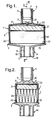
- the filter/HME has an outer housing 1 in two parts: an upper part 2 and a lower part 3.
- the upper part 2 is of rectangular shape with an internal width (that is, its longer lateral dimension) of about 65mm and a depth (its shorter lateral dimension) of about 40mm.
- the upper part 2 has a roof 4 with a shallow dome and a patient end, inlet port 5 located centrally on the roof.
- the port 5 is circular in section with an internal diameter of about 14mm and an external male taper 6; its inside has a female taper.
- a thin strut 8 extends laterally across the underside of the roof 4 and diametrically across the lower end of the port 5.
- the strut 8 supports a flow deflector 10 of novel shape.
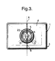
- the deflector 10 has an oval lateral section, that is, when viewed in plan, being about 11mm long and 5mm wide, so that its longer lateral dimension is about twice its shorter dimension.
- the longer axis "a" of the oval is aligned with the depth of the housing 1 (that is, its shorter lateral dimension), the shorter axis "b” being aligned with the width of the housing (that is, its longer lateral dimension).
- the upper surface 11 of the deflector 10 is convex, when viewed from above, and projects about 3mm above the upper surface of the strut 8.
- the lower end of the upper part 2 of the housing 1 is open and is joined to the upper end of the lower part 3.
- the lower part 3 has a domed rectangular plate 13, similar in shape to that of the roof 4, the outer edge of the plate 13 being bonded to the lower end of the upper part.
- the lower part 3 also has an outlet, machine end port 14 located centrally of the plate 13 and in line with the patient end port 5.
- the outlet port 14 has two concentric sleeves 15 and 16.
- the inner surface 17 of the outer sleeve 15 has a female taper; the outer surface 18 of the inner sleeve 16 has a male taper.
- the filter/HME includes a filter element 20 and an HME element 21 within the housing 1.
- the filter element 20 is of a pleated paper, with the pleats extending parallel to the width of the housing, and is located at the lower end of the housing 1, being sealed around its edge 22 to the inside of the housing.
- Other conventional filters could be used.
- the HME element 21 may be of any conventional kind, and sits on top of the filter element 20, between it and the inlet port 5.
- the two elements 20 and 21 are of rectangular shape in lateral section, conforming to the inside shape of the housing.
- the upper surface 23 of the HME element 21 abuts the lower surface of the strut 8, which ensures that there is clearance between the HME element and the underside of the roof 4.
- the filter/HME is connected in a patient breathing circuit (not shown), with the port 5 coupled to a tracheal tube or mask, and with the other port 14 connected to ventilation or anaesthesia apparatus, or left open to atmosphere if the patient is breathing spontaneously.
- gas flows through the port 5 over the surface 11 of the deflector 10.
- the shape of the deflector 10 is such that less gas is diverted in directions along the major axis "a" of the deflector, and more gas is diverted in directions along its minor axis "b".
- the orientation of deflector 10 and its shape ensures that gas is deflected preferentially along the longer lateral dimension of the housing than the shorter dimension.
- Inhaled gas flbws in through the machine port 5 and through the filter element 20.
- a deflector at the machine end of the device because the pleats help channel gas along the width of the housing.
- Any bacteria, viruses or particles in the incoming gas are filtered out by the filter element 20 before reaching the HME element 21.
- the filter element 20 also transfers some of its retained heat and moisture to the incoming gas. When the gas passes through the HME element 21, it takes up a part of the heat and moisture in the HME element, so the gas supplied to the patient is filtered, warmed and increased in humidity.
- the device described above only has a flow deflector at one end because the pleats of the filter act to channel inspiratory gas across the width of the device, thereby ensuring that it is distributed evenly across the device.
- a deflector at both ends of the device.
Abstract
Description
Claims (9)
- A gas treatment device including an outer housing (1) having an inlet port (5) and an outlet port (14), a gas treatment element (20, 21) located in the housing between the two ports and a gas flow deflector (10) located in the housing between the element (20, 21) and the inlet port (5), characterised in that the element (20, 21) has a surface (23) with an asymmetric shape presented to the gas flow, and that the gas flow deflector (10) has an asymmetric shape about the axis of the inlet port (5) such as to distribute gas more equally over the surface (23) of the element (20, 21).
- A device according to Claim 1, characterised in that the housing (1) and the gas treatment element (20, 21) are rectangular in section.
- A device according to Claim 1 or 2, characterised in that the deflector (10) is oval in lateral section with a convex surface (11) presented to the inlet port (5), and that the longer lateral axis of the deflector is aligned with the shorter lateral dimension of the gas treatment element (20, 21).
- A device according to any one of the preceding claims, characterised in that the longer lateral dimension of the gas flow deflector (10) is approximately twice that of its shorter lateral dimension.
- A device according to any one of the preceding claims, characterised in that the gas treatment element includes a filter (20).
- A device according to Claim 5, characterised in that the filter (20) is pleated with pleats extending parallel to the longer lateral dimension of the housing (1).
- A device according to any one of the preceding claims, characterised in that the gas treatment element includes an HME element (21).
- A device according to Claim 7 and Claim 5 or 6, characterised in that the filter (20) is located at one end of the housing (1) and the HME element (21) is located at the opposite end.
- A device according to Claim 8, characterised in that the HME element (21) is located towards the inlet port (5) and the filter (20) is located towards the outlet port (14).
Applications Claiming Priority (2)
| Application Number | Priority Date | Filing Date | Title |
|---|---|---|---|
| GBGB9704241.0A GB9704241D0 (en) | 1997-02-28 | 1997-02-28 | Gas-treatment devices |
| GB9704241 | 1997-02-28 |
Publications (2)
| Publication Number | Publication Date |
|---|---|
| EP0861671A2 true EP0861671A2 (en) | 1998-09-02 |
| EP0861671A3 EP0861671A3 (en) | 1999-06-09 |
Family
ID=10808513
Family Applications (1)
| Application Number | Title | Priority Date | Filing Date |
|---|---|---|---|
| EP98300736A Withdrawn EP0861671A3 (en) | 1997-02-28 | 1998-02-02 | Gas treatment devices |
Country Status (7)
| Country | Link |
|---|---|
| US (1) | US6017374A (en) |
| EP (1) | EP0861671A3 (en) |
| JP (1) | JPH10235126A (en) |
| AU (1) | AU728619B2 (en) |
| GB (2) | GB9704241D0 (en) |
| NZ (1) | NZ329707A (en) |
| ZA (1) | ZA981163B (en) |
Cited By (7)
| Publication number | Priority date | Publication date | Assignee | Title |
|---|---|---|---|---|
| WO2002068059A1 (en) | 2001-02-26 | 2002-09-06 | Safe Pipe Ab | Fire smoke cleaner |
| WO2008132222A2 (en) * | 2007-04-30 | 2008-11-06 | Atos Medical Ab | Breathing protector |
| EP1994952A1 (en) * | 2007-05-21 | 2008-11-26 | Covidien AG | Medical heat and moisture exchanger (HME) |
| EP1693081B1 (en) * | 2005-02-17 | 2011-01-05 | Andreas Fahl Medizintechnik-Vertrieb GmbH | Heat and moisture exchanger |
| US7892307B2 (en) * | 2007-07-27 | 2011-02-22 | Mann + Hummel Gmbh | Compact filter |
| EP2332630A1 (en) * | 2009-11-18 | 2011-06-15 | Covidien AG | Filter for a breathing circuit |
| US10315147B2 (en) | 2014-09-15 | 2019-06-11 | Donaldson Company, Inc. | Filter cartridges; air cleaner assemblies; housings; features; components; and, methods |
Families Citing this family (14)
| Publication number | Priority date | Publication date | Assignee | Title |
|---|---|---|---|---|
| KR100272513B1 (en) * | 1998-09-08 | 2001-01-15 | 구본준 | Etching Device of Glass Substrate |
| US6105576A (en) * | 1998-10-14 | 2000-08-22 | Enternet Medical, Inc. | Apparatus for treating respiratory gases including liquid trap |
| US6792946B1 (en) * | 2003-08-13 | 2004-09-21 | James V. Waldo, Jr. | Heat-moisture exchanger with aerosol by-pass |
| AU2007283436A1 (en) * | 2006-08-09 | 2008-02-14 | Compumedics Medical Innovation Pty Ltd | Air filter for a mask assembly |
| US7993071B2 (en) | 2006-10-25 | 2011-08-09 | Burrell E. Clawson | Assemblies for coupling two elements and coupled assemblies |
| CN101352635B (en) * | 2007-12-14 | 2011-01-05 | 宁波亚德客自动化工业有限公司 | Flow-guiding means component |
| US8561606B2 (en) | 2008-06-05 | 2013-10-22 | Carefusion 2200, Inc. | Heat and moisture exchange unit |
| US8414682B2 (en) * | 2010-02-22 | 2013-04-09 | Criticare Systems, Inc. | Inline water trap |
| US9415180B2 (en) | 2010-03-08 | 2016-08-16 | Atos Medical Ab | Breathing protector |
| US8844533B2 (en) | 2011-06-22 | 2014-09-30 | Breathe Technologies, Inc. | Ventilation mask with integrated piloted exhalation valve |
| US9486602B2 (en) | 2011-06-22 | 2016-11-08 | Breathe Technologies, Inc. | Ventilation mask with integrated piloted exhalation valve and method of ventilating a patient using the same |
| US9038634B2 (en) | 2011-06-22 | 2015-05-26 | Breathe Technologies, Inc. | Ventilation mask with integrated piloted exhalation valve |
| US9878121B2 (en) | 2013-03-13 | 2018-01-30 | Breathe Technologies, Inc. | Ventilation mask with heat and moisture exchange device |
| CN105343978A (en) * | 2015-10-20 | 2016-02-24 | 江苏苏云医疗器材有限公司 | Disposable heat and moisture exchanger |
Citations (1)
| Publication number | Priority date | Publication date | Assignee | Title |
|---|---|---|---|---|
| GB2231509A (en) | 1989-05-19 | 1990-11-21 | Intersurgical | Filters |
Family Cites Families (16)
| Publication number | Priority date | Publication date | Assignee | Title |
|---|---|---|---|---|
| BE772631A (en) * | 1970-09-15 | 1972-01-17 | Heil Process Equipment Corp | LIQUID ELIMINATOR |
| BE788210A (en) * | 1971-09-16 | 1973-02-28 | Pall Corp | FILTER BOX |
| FR2275240A1 (en) * | 1974-06-21 | 1976-01-16 | Stein Industrie | DEVICE FOR PRE-SEPARATING WATER DROPS FROM A BIPHASIC FLOW |
| US4483696A (en) * | 1982-09-07 | 1984-11-20 | Foster Wheeler Energy Corporation | Steam separating apparatus and separators used therein |
| DE3888914T2 (en) * | 1987-10-14 | 1994-11-24 | Nippon Oxygen Co Ltd | Breathing apparatus. |
| US4836834A (en) * | 1988-04-29 | 1989-06-06 | Dynamic Air Inc. | Air filter with back flow cleaning |
| US5213096A (en) * | 1990-06-18 | 1993-05-25 | Gambro Engstrom Ab | Apparatus for connecting a patient to breathing devices, the apparatus including a bacteria filter and gas sampling means |
| SE469925B (en) * | 1992-02-21 | 1993-10-11 | Gibeck Respiration Ab | A filter device for connection to a person's respiratory system comprising a housing containing a moisture-heat-exchanging material and a bacteria-absorbing filter consisting of a pleated, air-permeable material |
| GB9212399D0 (en) * | 1992-06-11 | 1992-07-22 | Pall Corp | Heat and moisture exchanging filters |
| GB2267840B (en) * | 1992-06-19 | 1995-09-20 | Intersurgical Ltd | Improvements in heat and moisture exchangers |
| US5376270A (en) * | 1993-06-24 | 1994-12-27 | Porous Media Corporation | Box filter |
| IL111162A (en) * | 1994-10-04 | 1998-01-04 | Irad Technologies Ltd | Filtering device utilizable with gas monitors |
| US5549722A (en) * | 1994-12-30 | 1996-08-27 | Dana Corporation | Air filter assemblies and a frustoconical air filter element for use with the assemblies |
| US5584899A (en) * | 1995-07-24 | 1996-12-17 | Shorts; Kevin L. | Fluid collection and filtration apparatus |
| US5590644A (en) * | 1995-10-19 | 1997-01-07 | Med-Plastics, Intl., Inc. | Heat and moisture exchanger for breathing |
| JP3024212U (en) * | 1995-10-30 | 1996-05-17 | 有限会社ゴーイング東京 | Filter element for engine air cleaner |
-
1997
- 1997-02-28 GB GBGB9704241.0A patent/GB9704241D0/en active Pending
-
1998
- 1998-02-02 EP EP98300736A patent/EP0861671A3/en not_active Withdrawn
- 1998-02-03 AU AU52896/98A patent/AU728619B2/en not_active Ceased
- 1998-02-05 GB GB9802342A patent/GB2322568B/en not_active Expired - Fee Related
- 1998-02-05 NZ NZ329707A patent/NZ329707A/en unknown
- 1998-02-06 US US09/019,687 patent/US6017374A/en not_active Expired - Fee Related
- 1998-02-12 ZA ZA981163A patent/ZA981163B/en unknown
- 1998-02-27 JP JP10046916A patent/JPH10235126A/en active Pending
Patent Citations (1)
| Publication number | Priority date | Publication date | Assignee | Title |
|---|---|---|---|---|
| GB2231509A (en) | 1989-05-19 | 1990-11-21 | Intersurgical | Filters |
Cited By (14)
| Publication number | Priority date | Publication date | Assignee | Title |
|---|---|---|---|---|
| EP1372789A1 (en) * | 2001-02-26 | 2004-01-02 | Safe Pipe AB | Fire smoke cleaner |
| WO2002068059A1 (en) | 2001-02-26 | 2002-09-06 | Safe Pipe Ab | Fire smoke cleaner |
| EP1693081B1 (en) * | 2005-02-17 | 2011-01-05 | Andreas Fahl Medizintechnik-Vertrieb GmbH | Heat and moisture exchanger |
| US8505537B2 (en) | 2007-04-30 | 2013-08-13 | Atos Medical Ab | Breathing protector |
| WO2008132222A2 (en) * | 2007-04-30 | 2008-11-06 | Atos Medical Ab | Breathing protector |
| WO2008132222A3 (en) * | 2007-04-30 | 2009-01-22 | Atos Medical Ab | Breathing protector |
| EP3701990A1 (en) * | 2007-04-30 | 2020-09-02 | Atos Medical AB | Breathing protector |
| EP1994952A1 (en) * | 2007-05-21 | 2008-11-26 | Covidien AG | Medical heat and moisture exchanger (HME) |
| CN101310787B (en) * | 2007-05-21 | 2013-04-24 | 柯惠股份公司 | Medical heat and moisture exchanger (hme) |
| US7892307B2 (en) * | 2007-07-27 | 2011-02-22 | Mann + Hummel Gmbh | Compact filter |
| EP2332630A1 (en) * | 2009-11-18 | 2011-06-15 | Covidien AG | Filter for a breathing circuit |
| US10315147B2 (en) | 2014-09-15 | 2019-06-11 | Donaldson Company, Inc. | Filter cartridges; air cleaner assemblies; housings; features; components; and, methods |
| US11123672B2 (en) | 2014-09-15 | 2021-09-21 | Donaldson Company, Inc. | Filter cartridges; air cleaner assemblies; housings; features; components; and, methods |
| US11772026B2 (en) | 2014-09-15 | 2023-10-03 | Donaldson Company, Inc. | Filter cartridges; air cleaner assemblies; housings; features; components; and, methods |
Also Published As
| Publication number | Publication date |
|---|---|
| NZ329707A (en) | 1999-06-29 |
| US6017374A (en) | 2000-01-25 |
| GB9802342D0 (en) | 1998-04-01 |
| GB2322568A (en) | 1998-09-02 |
| ZA981163B (en) | 1998-08-20 |
| JPH10235126A (en) | 1998-09-08 |
| AU728619B2 (en) | 2001-01-11 |
| GB9704241D0 (en) | 1997-04-16 |
| AU5289698A (en) | 1998-09-03 |
| EP0861671A3 (en) | 1999-06-09 |
| GB2322568B (en) | 2000-09-27 |
Similar Documents
| Publication | Publication Date | Title |
|---|---|---|
| US6017374A (en) | Gas treatment devices | |
| US5482031A (en) | Arrangement for connecting a patient to a respirator, and the use of a moisture-heat-exchanger in the arrangement | |
| US5035236A (en) | Filtration device for respiratory gasses with heat and moisture exchange | |
| US4971054A (en) | Breathing valve | |
| US6733556B1 (en) | Antibacterial/antiviral filtering device for ventilation systems | |
| US5590644A (en) | Heat and moisture exchanger for breathing | |
| CN1655849B (en) | Nose mask | |
| US5213096A (en) | Apparatus for connecting a patient to breathing devices, the apparatus including a bacteria filter and gas sampling means | |
| CA2364183A1 (en) | Nasal ventilation interface | |
| US6619287B2 (en) | Filter | |
| JPH07506983A (en) | Filter devices for human airway connections and their use | |
| FR2647680B1 (en) | OXYGENO-PHONATION VALVE AND TRACHEOTOMY CANNULA CAP COMPRISING SAID OXYGENO-PHONATION VALVE | |
| JP5801827B2 (en) | Breathing protector | |
| CA2098132A1 (en) | Heat and Moisture Exchanging Filters | |
| JPH0686816A (en) | Connecting device for connecting patient to artificial respiratory apparatus | |
| CN106072919B (en) | Mouth mask | |
| US20050133028A1 (en) | Gas-treatment devices | |
| EP0856328A3 (en) | Fluid-treatment assemblies | |
| WO1997024153A1 (en) | Dual-filtered isolation valve for resuscitation | |
| CN204619106U (en) | Humidifier and the respirator comprising it | |
| WO1997001366A1 (en) | Respiratory aid appliance | |
| US6484723B2 (en) | Tracheostomy air filtration system | |
| SE0201858D0 (en) | Device for heat and moisture exchange between inhalation and exhalation air flows | |
| CN107126645B (en) | A kind of type nasal filter for respiration | |
| CN111494831B (en) | Air filtering artificial nose |
Legal Events
| Date | Code | Title | Description |
|---|---|---|---|
| PUAI | Public reference made under article 153(3) epc to a published international application that has entered the european phase |
Free format text: ORIGINAL CODE: 0009012 |
|
| AK | Designated contracting states |
Kind code of ref document: A2 Designated state(s): DE DK ES FR GB GR IE IT NL SE |
|
| AX | Request for extension of the european patent |
Free format text: AL;LT;LV;MK;RO;SI |
|
| PUAL | Search report despatched |
Free format text: ORIGINAL CODE: 0009013 |
|
| AK | Designated contracting states |
Kind code of ref document: A3 Designated state(s): AT BE CH DE DK ES FI FR GB GR IE IT LI LU MC NL PT SE |
|
| AX | Request for extension of the european patent |
Free format text: AL;LT;LV;MK;RO;SI |
|
| 17P | Request for examination filed |
Effective date: 19991101 |
|
| AKX | Designation fees paid |
Free format text: DE DK ES FR GB GR IE IT NL SE |
|
| STAA | Information on the status of an ep patent application or granted ep patent |
Free format text: STATUS: THE APPLICATION IS DEEMED TO BE WITHDRAWN |
|
| 18D | Application deemed to be withdrawn |
Effective date: 20010901 |