EP1994949A1 - Scaffold material - Google Patents
Scaffold material Download PDFInfo
- Publication number
- EP1994949A1 EP1994949A1 EP07738224A EP07738224A EP1994949A1 EP 1994949 A1 EP1994949 A1 EP 1994949A1 EP 07738224 A EP07738224 A EP 07738224A EP 07738224 A EP07738224 A EP 07738224A EP 1994949 A1 EP1994949 A1 EP 1994949A1
- Authority
- EP
- European Patent Office
- Prior art keywords
- scaffold
- fibers
- scaffold according
- cell
- aligned
- Prior art date
- Legal status (The legal status is an assumption and is not a legal conclusion. Google has not performed a legal analysis and makes no representation as to the accuracy of the status listed.)
- Withdrawn
Links
- 239000000463 material Substances 0.000 title claims abstract description 16
- 239000000835 fiber Substances 0.000 claims abstract description 115
- 229920000249 biocompatible polymer Polymers 0.000 claims abstract description 22
- 239000006143 cell culture medium Substances 0.000 claims abstract description 4
- 238000000034 method Methods 0.000 claims description 29
- 238000004804 winding Methods 0.000 claims description 24
- 238000004519 manufacturing process Methods 0.000 claims description 13
- 230000005611 electricity Effects 0.000 claims description 10
- 230000003068 static effect Effects 0.000 claims description 10
- 230000005686 electrostatic field Effects 0.000 claims description 9
- 229920001577 copolymer Polymers 0.000 claims description 8
- 229920003232 aliphatic polyester Polymers 0.000 claims description 6
- 238000005520 cutting process Methods 0.000 claims description 5
- 229920000954 Polyglycolide Polymers 0.000 claims description 4
- 229920000747 poly(lactic acid) Polymers 0.000 claims description 4
- 229920001610 polycaprolactone Polymers 0.000 claims description 4
- 239000004632 polycaprolactone Substances 0.000 claims description 4
- 239000004633 polyglycolic acid Substances 0.000 claims description 4
- 239000004626 polylactic acid Substances 0.000 claims description 4
- 230000001172 regenerating effect Effects 0.000 claims description 4
- 230000010261 cell growth Effects 0.000 abstract description 11
- 210000004027 cell Anatomy 0.000 description 27
- LFQSCWFLJHTTHZ-UHFFFAOYSA-N Ethanol Chemical compound CCO LFQSCWFLJHTTHZ-UHFFFAOYSA-N 0.000 description 18
- -1 polytrimethylene carbonate Polymers 0.000 description 15
- 210000001519 tissue Anatomy 0.000 description 13
- YMWUJEATGCHHMB-UHFFFAOYSA-N Dichloromethane Chemical compound ClCCl YMWUJEATGCHHMB-UHFFFAOYSA-N 0.000 description 12
- 239000002904 solvent Substances 0.000 description 11
- 239000011148 porous material Substances 0.000 description 10
- 238000001523 electrospinning Methods 0.000 description 9
- 238000009825 accumulation Methods 0.000 description 8
- 229920000642 polymer Polymers 0.000 description 8
- 238000009987 spinning Methods 0.000 description 8
- CSCPPACGZOOCGX-UHFFFAOYSA-N Acetone Chemical compound CC(C)=O CSCPPACGZOOCGX-UHFFFAOYSA-N 0.000 description 6
- CURLTUGMZLYLDI-UHFFFAOYSA-N Carbon dioxide Chemical compound O=C=O CURLTUGMZLYLDI-UHFFFAOYSA-N 0.000 description 6
- WSFSSNUMVMOOMR-UHFFFAOYSA-N Formaldehyde Chemical compound O=C WSFSSNUMVMOOMR-UHFFFAOYSA-N 0.000 description 6
- JVTAAEKCZFNVCJ-UHFFFAOYSA-N lactic acid Chemical compound CC(O)C(O)=O JVTAAEKCZFNVCJ-UHFFFAOYSA-N 0.000 description 6
- XLYOFNOQVPJJNP-UHFFFAOYSA-N water Substances O XLYOFNOQVPJJNP-UHFFFAOYSA-N 0.000 description 6
- AEMRFAOFKBGASW-UHFFFAOYSA-N Glycolic acid Chemical compound OCC(O)=O AEMRFAOFKBGASW-UHFFFAOYSA-N 0.000 description 5
- 230000006835 compression Effects 0.000 description 5
- 238000007906 compression Methods 0.000 description 5
- 238000011156 evaluation Methods 0.000 description 5
- 230000001788 irregular Effects 0.000 description 5
- HEDRZPFGACZZDS-UHFFFAOYSA-N Chloroform Chemical compound ClC(Cl)Cl HEDRZPFGACZZDS-UHFFFAOYSA-N 0.000 description 4
- DHCLVCXQIBBOPH-UHFFFAOYSA-N Glycerol 2-phosphate Chemical compound OCC(CO)OP(O)(O)=O DHCLVCXQIBBOPH-UHFFFAOYSA-N 0.000 description 4
- 229910002092 carbon dioxide Inorganic materials 0.000 description 4
- 239000012091 fetal bovine serum Substances 0.000 description 4
- 239000003102 growth factor Substances 0.000 description 4
- 239000007788 liquid Substances 0.000 description 4
- 238000005259 measurement Methods 0.000 description 4
- 239000007758 minimum essential medium Substances 0.000 description 4
- 239000000523 sample Substances 0.000 description 4
- 239000000126 substance Substances 0.000 description 4
- BYEAHWXPCBROCE-UHFFFAOYSA-N 1,1,1,3,3,3-hexafluoropropan-2-ol Chemical compound FC(F)(F)C(O)C(F)(F)F BYEAHWXPCBROCE-UHFFFAOYSA-N 0.000 description 3
- WEVYAHXRMPXWCK-UHFFFAOYSA-N Acetonitrile Chemical compound CC#N WEVYAHXRMPXWCK-UHFFFAOYSA-N 0.000 description 3
- OKKJLVBELUTLKV-UHFFFAOYSA-N Methanol Chemical compound OC OKKJLVBELUTLKV-UHFFFAOYSA-N 0.000 description 3
- ZMXDDKWLCZADIW-UHFFFAOYSA-N N,N-Dimethylformamide Chemical compound CN(C)C=O ZMXDDKWLCZADIW-UHFFFAOYSA-N 0.000 description 3
- YXFVVABEGXRONW-UHFFFAOYSA-N Toluene Chemical compound CC1=CC=CC=C1 YXFVVABEGXRONW-UHFFFAOYSA-N 0.000 description 3
- 239000002543 antimycotic Substances 0.000 description 3
- 238000012925 biological evaluation Methods 0.000 description 3
- 239000003814 drug Substances 0.000 description 3
- 230000012010 growth Effects 0.000 description 3
- 238000010438 heat treatment Methods 0.000 description 3
- 238000000338 in vitro Methods 0.000 description 3
- 238000001727 in vivo Methods 0.000 description 3
- 229960000448 lactic acid Drugs 0.000 description 3
- 210000002901 mesenchymal stem cell Anatomy 0.000 description 3
- 238000002360 preparation method Methods 0.000 description 3
- 238000011069 regeneration method Methods 0.000 description 3
- 238000012360 testing method Methods 0.000 description 3
- KIUKXJAPPMFGSW-DNGZLQJQSA-N (2S,3S,4S,5R,6R)-6-[(2S,3R,4R,5S,6R)-3-Acetamido-2-[(2S,3S,4R,5R,6R)-6-[(2R,3R,4R,5S,6R)-3-acetamido-2,5-dihydroxy-6-(hydroxymethyl)oxan-4-yl]oxy-2-carboxy-4,5-dihydroxyoxan-3-yl]oxy-5-hydroxy-6-(hydroxymethyl)oxan-4-yl]oxy-3,4,5-trihydroxyoxane-2-carboxylic acid Chemical compound CC(=O)N[C@H]1[C@H](O)O[C@H](CO)[C@@H](O)[C@@H]1O[C@H]1[C@H](O)[C@@H](O)[C@H](O[C@H]2[C@@H]([C@@H](O[C@H]3[C@@H]([C@@H](O)[C@H](O)[C@H](O3)C(O)=O)O)[C@H](O)[C@@H](CO)O2)NC(C)=O)[C@@H](C(O)=O)O1 KIUKXJAPPMFGSW-DNGZLQJQSA-N 0.000 description 2
- 229920002101 Chitin Polymers 0.000 description 2
- 229920001661 Chitosan Polymers 0.000 description 2
- 108010035532 Collagen Proteins 0.000 description 2
- 102000008186 Collagen Human genes 0.000 description 2
- RTZKZFJDLAIYFH-UHFFFAOYSA-N Diethyl ether Chemical compound CCOCC RTZKZFJDLAIYFH-UHFFFAOYSA-N 0.000 description 2
- QXNVGIXVLWOKEQ-UHFFFAOYSA-N Disodium Chemical compound [Na][Na] QXNVGIXVLWOKEQ-UHFFFAOYSA-N 0.000 description 2
- 102000018386 EGF Family of Proteins Human genes 0.000 description 2
- 108010066486 EGF Family of Proteins Proteins 0.000 description 2
- 108010010803 Gelatin Proteins 0.000 description 2
- 229920002148 Gellan gum Polymers 0.000 description 2
- KFZMGEQAYNKOFK-UHFFFAOYSA-N Isopropanol Chemical compound CC(C)O KFZMGEQAYNKOFK-UHFFFAOYSA-N 0.000 description 2
- ACFGRWJEQJVZTM-LEJBHHMKSA-L Magnesium L-ascorbic acid-2-phosphate Chemical class [Mg+2].OC[C@H](O)[C@H]1OC(=O)C(OP([O-])([O-])=O)=C1O ACFGRWJEQJVZTM-LEJBHHMKSA-L 0.000 description 2
- 108010072582 Matrilin Proteins Proteins 0.000 description 2
- 102000055008 Matrilin Proteins Human genes 0.000 description 2
- 108010025020 Nerve Growth Factor Proteins 0.000 description 2
- 102000007072 Nerve Growth Factors Human genes 0.000 description 2
- 229910019142 PO4 Inorganic materials 0.000 description 2
- WYURNTSHIVDZCO-UHFFFAOYSA-N Tetrahydrofuran Chemical compound C1CCOC1 WYURNTSHIVDZCO-UHFFFAOYSA-N 0.000 description 2
- 229920004890 Triton X-100 Polymers 0.000 description 2
- 235000010443 alginic acid Nutrition 0.000 description 2
- 239000000783 alginic acid Substances 0.000 description 2
- 229920000615 alginic acid Polymers 0.000 description 2
- 229960001126 alginic acid Drugs 0.000 description 2
- 150000004781 alginic acids Chemical class 0.000 description 2
- 150000005215 alkyl ethers Chemical class 0.000 description 2
- QVGXLLKOCUKJST-UHFFFAOYSA-N atomic oxygen Chemical compound [O] QVGXLLKOCUKJST-UHFFFAOYSA-N 0.000 description 2
- 150000001720 carbohydrates Chemical class 0.000 description 2
- 235000014633 carbohydrates Nutrition 0.000 description 2
- 239000001569 carbon dioxide Substances 0.000 description 2
- 210000000845 cartilage Anatomy 0.000 description 2
- 239000001913 cellulose Substances 0.000 description 2
- 229920002678 cellulose Polymers 0.000 description 2
- 235000010980 cellulose Nutrition 0.000 description 2
- 229940045110 chitosan Drugs 0.000 description 2
- 229920001436 collagen Polymers 0.000 description 2
- JHIVVAPYMSGYDF-UHFFFAOYSA-N cyclohexanone Chemical compound O=C1CCCCC1 JHIVVAPYMSGYDF-UHFFFAOYSA-N 0.000 description 2
- 230000004069 differentiation Effects 0.000 description 2
- LOKCTEFSRHRXRJ-UHFFFAOYSA-I dipotassium trisodium dihydrogen phosphate hydrogen phosphate dichloride Chemical compound P(=O)(O)(O)[O-].[K+].P(=O)(O)([O-])[O-].[Na+].[Na+].[Cl-].[K+].[Cl-].[Na+] LOKCTEFSRHRXRJ-UHFFFAOYSA-I 0.000 description 2
- 239000012153 distilled water Substances 0.000 description 2
- 238000001704 evaporation Methods 0.000 description 2
- 230000008020 evaporation Effects 0.000 description 2
- 239000004744 fabric Substances 0.000 description 2
- 238000005187 foaming Methods 0.000 description 2
- 238000004108 freeze drying Methods 0.000 description 2
- 229920000159 gelatin Polymers 0.000 description 2
- 239000008273 gelatin Substances 0.000 description 2
- 235000019322 gelatine Nutrition 0.000 description 2
- 235000011852 gelatine desserts Nutrition 0.000 description 2
- 239000001963 growth medium Substances 0.000 description 2
- 229920002674 hyaluronan Polymers 0.000 description 2
- 229960003160 hyaluronic acid Drugs 0.000 description 2
- 239000011147 inorganic material Substances 0.000 description 2
- 150000002500 ions Chemical class 0.000 description 2
- 239000004310 lactic acid Substances 0.000 description 2
- 235000014655 lactic acid Nutrition 0.000 description 2
- 229910052751 metal Inorganic materials 0.000 description 2
- 239000000178 monomer Substances 0.000 description 2
- 235000016709 nutrition Nutrition 0.000 description 2
- 230000035764 nutrition Effects 0.000 description 2
- 229910052760 oxygen Inorganic materials 0.000 description 2
- 239000001301 oxygen Substances 0.000 description 2
- 238000005191 phase separation Methods 0.000 description 2
- 239000010452 phosphate Substances 0.000 description 2
- 239000002953 phosphate buffered saline Substances 0.000 description 2
- 229920001308 poly(aminoacid) Polymers 0.000 description 2
- 229920002635 polyurethane Polymers 0.000 description 2
- 239000004814 polyurethane Substances 0.000 description 2
- 235000018102 proteins Nutrition 0.000 description 2
- 102000004169 proteins and genes Human genes 0.000 description 2
- 108090000623 proteins and genes Proteins 0.000 description 2
- 230000008929 regeneration Effects 0.000 description 2
- 239000000243 solution Substances 0.000 description 2
- 238000010186 staining Methods 0.000 description 2
- 150000003431 steroids Chemical class 0.000 description 2
- VZGDMQKNWNREIO-UHFFFAOYSA-N tetrachloromethane Chemical compound ClC(Cl)(Cl)Cl VZGDMQKNWNREIO-UHFFFAOYSA-N 0.000 description 2
- 238000002054 transplantation Methods 0.000 description 2
- 239000002699 waste material Substances 0.000 description 2
- FPJHWYCPAOPVIV-VOZMEZHOSA-N (2R,3S,4R,5R,6R)-6-[(2R,3R,4R,5R,6R)-5-acetamido-2-(hydroxymethyl)-6-methoxy-3-sulfooxyoxan-4-yl]oxy-4,5-dihydroxy-3-methoxyoxane-2-carboxylic acid Chemical compound CO[C@@H]1O[C@H](CO)[C@H](OS(O)(=O)=O)[C@H](O[C@@H]2O[C@H]([C@@H](OC)[C@H](O)[C@H]2O)C(O)=O)[C@H]1NC(C)=O FPJHWYCPAOPVIV-VOZMEZHOSA-N 0.000 description 1
- LUEWUZLMQUOBSB-FSKGGBMCSA-N (2s,3s,4s,5s,6r)-2-[(2r,3s,4r,5r,6s)-6-[(2r,3s,4r,5s,6s)-4,5-dihydroxy-2-(hydroxymethyl)-6-[(2r,4r,5s,6r)-4,5,6-trihydroxy-2-(hydroxymethyl)oxan-3-yl]oxyoxan-3-yl]oxy-4,5-dihydroxy-2-(hydroxymethyl)oxan-3-yl]oxy-6-(hydroxymethyl)oxane-3,4,5-triol Chemical compound O[C@H]1[C@@H](O)[C@H](O)[C@@H](CO)O[C@H]1O[C@@H]1[C@@H](CO)O[C@@H](O[C@@H]2[C@H](O[C@@H](OC3[C@H](O[C@@H](O)[C@@H](O)[C@H]3O)CO)[C@@H](O)[C@H]2O)CO)[C@H](O)[C@H]1O LUEWUZLMQUOBSB-FSKGGBMCSA-N 0.000 description 1
- BHQCQFFYRZLCQQ-UHFFFAOYSA-N (3alpha,5alpha,7alpha,12alpha)-3,7,12-trihydroxy-cholan-24-oic acid Natural products OC1CC2CC(O)CCC2(C)C2C1C1CCC(C(CCC(O)=O)C)C1(C)C(O)C2 BHQCQFFYRZLCQQ-UHFFFAOYSA-N 0.000 description 1
- TZCPCKNHXULUIY-RGULYWFUSA-N 1,2-distearoyl-sn-glycero-3-phosphoserine Chemical compound CCCCCCCCCCCCCCCCCC(=O)OC[C@H](COP(O)(=O)OC[C@H](N)C(O)=O)OC(=O)CCCCCCCCCCCCCCCCC TZCPCKNHXULUIY-RGULYWFUSA-N 0.000 description 1
- RYHBNJHYFVUHQT-UHFFFAOYSA-N 1,4-Dioxane Chemical compound C1COCCO1 RYHBNJHYFVUHQT-UHFFFAOYSA-N 0.000 description 1
- SQDAZGGFXASXDW-UHFFFAOYSA-N 5-bromo-2-(trifluoromethoxy)pyridine Chemical compound FC(F)(F)OC1=CC=C(Br)C=N1 SQDAZGGFXASXDW-UHFFFAOYSA-N 0.000 description 1
- 244000215068 Acacia senegal Species 0.000 description 1
- 229920001817 Agar Polymers 0.000 description 1
- 102000007350 Bone Morphogenetic Proteins Human genes 0.000 description 1
- 108010007726 Bone Morphogenetic Proteins Proteins 0.000 description 1
- 108091003079 Bovine Serum Albumin Proteins 0.000 description 1
- 229920002134 Carboxymethyl cellulose Polymers 0.000 description 1
- 108010076119 Caseins Proteins 0.000 description 1
- 102000011632 Caseins Human genes 0.000 description 1
- YBSQGNFRWZKFMJ-UHFFFAOYSA-N Cerebroside B Natural products CCCCCCCCCCCCCCC(O)C(=O)NC(C(O)C=CCCC=C(C)CCCCCCCCC)COC1OC(CO)C(O)C(O)C1O YBSQGNFRWZKFMJ-UHFFFAOYSA-N 0.000 description 1
- 239000004380 Cholic acid Substances 0.000 description 1
- 229920002567 Chondroitin Polymers 0.000 description 1
- 229920001287 Chondroitin sulfate Polymers 0.000 description 1
- 229920002558 Curdlan Polymers 0.000 description 1
- 239000001879 Curdlan Substances 0.000 description 1
- XDTMQSROBMDMFD-UHFFFAOYSA-N Cyclohexane Chemical compound C1CCCCC1 XDTMQSROBMDMFD-UHFFFAOYSA-N 0.000 description 1
- 229920000045 Dermatan sulfate Polymers 0.000 description 1
- 229920002307 Dextran Polymers 0.000 description 1
- WDJUZGPOPHTGOT-OAXVISGBSA-N Digitoxin Natural products O([C@H]1[C@@H](C)O[C@@H](O[C@@H]2C[C@@H]3[C@@](C)([C@@H]4[C@H]([C@]5(O)[C@@](C)([C@H](C6=CC(=O)OC6)CC5)CC4)CC3)CC2)C[C@H]1O)[C@H]1O[C@@H](C)[C@H](O[C@H]2O[C@@H](C)[C@@H](O)[C@@H](O)C2)[C@@H](O)C1 WDJUZGPOPHTGOT-OAXVISGBSA-N 0.000 description 1
- 102000016942 Elastin Human genes 0.000 description 1
- 108010014258 Elastin Proteins 0.000 description 1
- 108090000790 Enzymes Proteins 0.000 description 1
- 102000004190 Enzymes Human genes 0.000 description 1
- 108010037362 Extracellular Matrix Proteins Proteins 0.000 description 1
- 102000010834 Extracellular Matrix Proteins Human genes 0.000 description 1
- 102000009123 Fibrin Human genes 0.000 description 1
- 108010073385 Fibrin Proteins 0.000 description 1
- BWGVNKXGVNDBDI-UHFFFAOYSA-N Fibrin monomer Chemical compound CNC(=O)CNC(=O)CN BWGVNKXGVNDBDI-UHFFFAOYSA-N 0.000 description 1
- 108010067306 Fibronectins Proteins 0.000 description 1
- 102000016359 Fibronectins Human genes 0.000 description 1
- 229920002581 Glucomannan Polymers 0.000 description 1
- JZNWSCPGTDBMEW-UHFFFAOYSA-N Glycerophosphorylethanolamin Natural products NCCOP(O)(=O)OCC(O)CO JZNWSCPGTDBMEW-UHFFFAOYSA-N 0.000 description 1
- ZWZWYGMENQVNFU-UHFFFAOYSA-N Glycerophosphorylserin Natural products OC(=O)C(N)COP(O)(=O)OCC(O)CO ZWZWYGMENQVNFU-UHFFFAOYSA-N 0.000 description 1
- 229930186217 Glycolipid Natural products 0.000 description 1
- 229920000084 Gum arabic Polymers 0.000 description 1
- 229920000569 Gum karaya Polymers 0.000 description 1
- HTTJABKRGRZYRN-UHFFFAOYSA-N Heparin Chemical compound OC1C(NC(=O)C)C(O)OC(COS(O)(=O)=O)C1OC1C(OS(O)(=O)=O)C(O)C(OC2C(C(OS(O)(=O)=O)C(OC3C(C(O)C(O)C(O3)C(O)=O)OS(O)(=O)=O)C(CO)O2)NS(O)(=O)=O)C(C(O)=O)O1 HTTJABKRGRZYRN-UHFFFAOYSA-N 0.000 description 1
- 108010076876 Keratins Proteins 0.000 description 1
- 102000011782 Keratins Human genes 0.000 description 1
- 108010085895 Laminin Proteins 0.000 description 1
- 102000007547 Laminin Human genes 0.000 description 1
- 239000004677 Nylon Substances 0.000 description 1
- 229920002230 Pectic acid Polymers 0.000 description 1
- 229920003171 Poly (ethylene oxide) Polymers 0.000 description 1
- 229920000805 Polyaspartic acid Polymers 0.000 description 1
- 239000004698 Polyethylene Substances 0.000 description 1
- 108010020346 Polyglutamic Acid Proteins 0.000 description 1
- 108010039918 Polylysine Proteins 0.000 description 1
- 239000004743 Polypropylene Substances 0.000 description 1
- 229920001214 Polysorbate 60 Polymers 0.000 description 1
- 239000004373 Pullulan Substances 0.000 description 1
- 229920001218 Pullulan Polymers 0.000 description 1
- 108010013296 Sericins Proteins 0.000 description 1
- 229920002472 Starch Polymers 0.000 description 1
- 241000934878 Sterculia Species 0.000 description 1
- 229930006000 Sucrose Natural products 0.000 description 1
- CZMRCDWAGMRECN-UGDNZRGBSA-N Sucrose Chemical compound O[C@H]1[C@H](O)[C@@H](CO)O[C@@]1(CO)O[C@@H]1[C@H](O)[C@@H](O)[C@H](O)[C@@H](CO)O1 CZMRCDWAGMRECN-UGDNZRGBSA-N 0.000 description 1
- 108090000190 Thrombin Proteins 0.000 description 1
- 102000009618 Transforming Growth Factors Human genes 0.000 description 1
- 108010009583 Transforming Growth Factors Proteins 0.000 description 1
- 241000425571 Trepanes Species 0.000 description 1
- 239000013504 Triton X-100 Substances 0.000 description 1
- 229920002000 Xyloglucan Polymers 0.000 description 1
- LEBBDRXHHNYZIA-LDUWYPJVSA-N [(2s,3r,4s,5r,6r)-3,4,5-trihydroxy-6-(hydroxymethyl)oxan-2-yl] n-[(z)-1,3-dihydroxyoctadec-4-en-2-yl]carbamate Chemical compound CCCCCCCCCCCCC\C=C/C(O)C(CO)NC(=O)O[C@@H]1O[C@H](CO)[C@H](O)[C@H](O)[C@H]1O LEBBDRXHHNYZIA-LDUWYPJVSA-N 0.000 description 1
- ATBOMIWRCZXYSZ-XZBBILGWSA-N [1-[2,3-dihydroxypropoxy(hydroxy)phosphoryl]oxy-3-hexadecanoyloxypropan-2-yl] (9e,12e)-octadeca-9,12-dienoate Chemical compound CCCCCCCCCCCCCCCC(=O)OCC(COP(O)(=O)OCC(O)CO)OC(=O)CCCCCCC\C=C\C\C=C\CCCCC ATBOMIWRCZXYSZ-XZBBILGWSA-N 0.000 description 1
- 235000010489 acacia gum Nutrition 0.000 description 1
- 239000000205 acacia gum Substances 0.000 description 1
- 239000008272 agar Substances 0.000 description 1
- 229940023476 agar Drugs 0.000 description 1
- 235000010419 agar Nutrition 0.000 description 1
- AWUCVROLDVIAJX-UHFFFAOYSA-N alpha-glycerophosphate Natural products OCC(O)COP(O)(O)=O AWUCVROLDVIAJX-UHFFFAOYSA-N 0.000 description 1
- 238000013459 approach Methods 0.000 description 1
- 239000007864 aqueous solution Substances 0.000 description 1
- 239000012237 artificial material Substances 0.000 description 1
- WPIHMWBQRSAMDE-YCZTVTEBSA-N beta-D-galactosyl-(1->4)-beta-D-galactosyl-N-(pentacosanoyl)sphingosine Chemical compound CCCCCCCCCCCCCCCCCCCCCCCCC(=O)N[C@@H](CO[C@@H]1O[C@H](CO)[C@H](O[C@@H]2O[C@H](CO)[C@H](O)[C@H](O)[C@H]2O)[C@H](O)[C@H]1O)[C@H](O)\C=C\CCCCCCCCCCCCC WPIHMWBQRSAMDE-YCZTVTEBSA-N 0.000 description 1
- WQZGKKKJIJFFOK-VFUOTHLCSA-N beta-D-glucose Chemical compound OC[C@H]1O[C@@H](O)[C@H](O)[C@@H](O)[C@@H]1O WQZGKKKJIJFFOK-VFUOTHLCSA-N 0.000 description 1
- 238000001574 biopsy Methods 0.000 description 1
- 210000003969 blast cell Anatomy 0.000 description 1
- 238000009835 boiling Methods 0.000 description 1
- 238000011088 calibration curve Methods 0.000 description 1
- 239000001768 carboxy methyl cellulose Substances 0.000 description 1
- 235000010948 carboxy methyl cellulose Nutrition 0.000 description 1
- 125000002057 carboxymethyl group Chemical group [H]OC(=O)C([H])([H])[*] 0.000 description 1
- 239000008112 carboxymethyl-cellulose Substances 0.000 description 1
- 235000010418 carrageenan Nutrition 0.000 description 1
- 239000000679 carrageenan Substances 0.000 description 1
- 229920001525 carrageenan Polymers 0.000 description 1
- 229940113118 carrageenan Drugs 0.000 description 1
- 239000005018 casein Substances 0.000 description 1
- BECPQYXYKAMYBN-UHFFFAOYSA-N casein, tech. Chemical compound NCCCCC(C(O)=O)N=C(O)C(CC(O)=O)N=C(O)C(CCC(O)=N)N=C(O)C(CC(C)C)N=C(O)C(CCC(O)=O)N=C(O)C(CC(O)=O)N=C(O)C(CCC(O)=O)N=C(O)C(C(C)O)N=C(O)C(CCC(O)=N)N=C(O)C(CCC(O)=N)N=C(O)C(CCC(O)=N)N=C(O)C(CCC(O)=O)N=C(O)C(CCC(O)=O)N=C(O)C(COP(O)(O)=O)N=C(O)C(CCC(O)=N)N=C(O)C(N)CC1=CC=CC=C1 BECPQYXYKAMYBN-UHFFFAOYSA-N 0.000 description 1
- 235000021240 caseins Nutrition 0.000 description 1
- 230000021164 cell adhesion Effects 0.000 description 1
- 230000024245 cell differentiation Effects 0.000 description 1
- 239000006285 cell suspension Substances 0.000 description 1
- 239000003153 chemical reaction reagent Substances 0.000 description 1
- 235000012000 cholesterol Nutrition 0.000 description 1
- 150000001841 cholesterols Chemical class 0.000 description 1
- 235000019416 cholic acid Nutrition 0.000 description 1
- BHQCQFFYRZLCQQ-OELDTZBJSA-N cholic acid Chemical compound C([C@H]1C[C@H]2O)[C@H](O)CC[C@]1(C)[C@@H]1[C@@H]2[C@@H]2CC[C@H]([C@@H](CCC(O)=O)C)[C@@]2(C)[C@@H](O)C1 BHQCQFFYRZLCQQ-OELDTZBJSA-N 0.000 description 1
- 229960002471 cholic acid Drugs 0.000 description 1
- DLGJWSVWTWEWBJ-HGGSSLSASA-N chondroitin Chemical compound CC(O)=N[C@@H]1[C@H](O)O[C@H](CO)[C@H](O)[C@@H]1OC1[C@H](O)[C@H](O)C=C(C(O)=O)O1 DLGJWSVWTWEWBJ-HGGSSLSASA-N 0.000 description 1
- 229940059329 chondroitin sulfate Drugs 0.000 description 1
- 239000002131 composite material Substances 0.000 description 1
- 238000010276 construction Methods 0.000 description 1
- 238000007334 copolymerization reaction Methods 0.000 description 1
- 210000004748 cultured cell Anatomy 0.000 description 1
- 235000019316 curdlan Nutrition 0.000 description 1
- 229940078035 curdlan Drugs 0.000 description 1
- 230000007423 decrease Effects 0.000 description 1
- 230000007547 defect Effects 0.000 description 1
- KXGVEGMKQFWNSR-UHFFFAOYSA-N deoxycholic acid Natural products C1CC2CC(O)CCC2(C)C2C1C1CCC(C(CCC(O)=O)C)C1(C)C(O)C2 KXGVEGMKQFWNSR-UHFFFAOYSA-N 0.000 description 1
- 229940051593 dermatan sulfate Drugs 0.000 description 1
- UREBDLICKHMUKA-CXSFZGCWSA-N dexamethasone Chemical compound C1CC2=CC(=O)C=C[C@]2(C)[C@]2(F)[C@@H]1[C@@H]1C[C@@H](C)[C@@](C(=O)CO)(O)[C@@]1(C)C[C@@H]2O UREBDLICKHMUKA-CXSFZGCWSA-N 0.000 description 1
- 229960003957 dexamethasone Drugs 0.000 description 1
- 229960002086 dextran Drugs 0.000 description 1
- 229960000633 dextran sulfate Drugs 0.000 description 1
- 235000013681 dietary sucrose Nutrition 0.000 description 1
- WDJUZGPOPHTGOT-XUDUSOBPSA-N digitoxin Chemical compound C1[C@H](O)[C@H](O)[C@@H](C)O[C@H]1O[C@@H]1[C@@H](C)O[C@@H](O[C@@H]2[C@H](O[C@@H](O[C@@H]3C[C@@H]4[C@]([C@@H]5[C@H]([C@]6(CC[C@@H]([C@@]6(C)CC5)C=5COC(=O)C=5)O)CC4)(C)CC3)C[C@@H]2O)C)C[C@@H]1O WDJUZGPOPHTGOT-XUDUSOBPSA-N 0.000 description 1
- 229960000648 digitoxin Drugs 0.000 description 1
- WQLVFSAGQJTQCK-UHFFFAOYSA-N diosgenin Natural products CC1C(C2(CCC3C4(C)CCC(O)CC4=CCC3C2C2)C)C2OC11CCC(C)CO1 WQLVFSAGQJTQCK-UHFFFAOYSA-N 0.000 description 1
- 238000006073 displacement reaction Methods 0.000 description 1
- 230000000694 effects Effects 0.000 description 1
- 229920002549 elastin Polymers 0.000 description 1
- 229940088598 enzyme Drugs 0.000 description 1
- 230000005284 excitation Effects 0.000 description 1
- 210000002744 extracellular matrix Anatomy 0.000 description 1
- 239000000284 extract Substances 0.000 description 1
- 229950003499 fibrin Drugs 0.000 description 1
- 239000002657 fibrous material Substances 0.000 description 1
- 235000010492 gellan gum Nutrition 0.000 description 1
- 239000000216 gellan gum Substances 0.000 description 1
- 150000002298 globosides Chemical class 0.000 description 1
- 229940046240 glucomannan Drugs 0.000 description 1
- 229920000591 gum Polymers 0.000 description 1
- 229920000669 heparin Polymers 0.000 description 1
- 229960002897 heparin Drugs 0.000 description 1
- 210000003494 hepatocyte Anatomy 0.000 description 1
- 229910052588 hydroxylapatite Inorganic materials 0.000 description 1
- 238000002513 implantation Methods 0.000 description 1
- 229910010272 inorganic material Inorganic materials 0.000 description 1
- 239000011810 insulating material Substances 0.000 description 1
- FZWBNHMXJMCXLU-BLAUPYHCSA-N isomaltotriose Chemical compound O[C@@H]1[C@@H](O)[C@H](O)[C@@H](CO)O[C@@H]1OC[C@@H]1[C@@H](O)[C@H](O)[C@@H](O)[C@@H](OC[C@@H](O)[C@@H](O)[C@H](O)[C@@H](O)C=O)O1 FZWBNHMXJMCXLU-BLAUPYHCSA-N 0.000 description 1
- 235000010494 karaya gum Nutrition 0.000 description 1
- 239000000231 karaya gum Substances 0.000 description 1
- 229940039371 karaya gum Drugs 0.000 description 1
- 210000000629 knee joint Anatomy 0.000 description 1
- 239000011159 matrix material Substances 0.000 description 1
- 239000002184 metal Substances 0.000 description 1
- 239000007769 metal material Substances 0.000 description 1
- 229920000609 methyl cellulose Polymers 0.000 description 1
- 125000002496 methyl group Chemical group [H]C([H])([H])* 0.000 description 1
- 239000001923 methylcellulose Substances 0.000 description 1
- 235000010981 methylcellulose Nutrition 0.000 description 1
- 238000001000 micrograph Methods 0.000 description 1
- 239000012046 mixed solvent Substances 0.000 description 1
- 239000000203 mixture Substances 0.000 description 1
- 239000002121 nanofiber Substances 0.000 description 1
- 239000005445 natural material Substances 0.000 description 1
- 229920005615 natural polymer Polymers 0.000 description 1
- 229920001778 nylon Polymers 0.000 description 1
- 239000011368 organic material Substances 0.000 description 1
- XYJRXVWERLGGKC-UHFFFAOYSA-D pentacalcium;hydroxide;triphosphate Chemical compound [OH-].[Ca+2].[Ca+2].[Ca+2].[Ca+2].[Ca+2].[O-]P([O-])([O-])=O.[O-]P([O-])([O-])=O.[O-]P([O-])([O-])=O XYJRXVWERLGGKC-UHFFFAOYSA-D 0.000 description 1
- NBIIXXVUZAFLBC-UHFFFAOYSA-K phosphate Chemical compound [O-]P([O-])([O-])=O NBIIXXVUZAFLBC-UHFFFAOYSA-K 0.000 description 1
- WTJKGGKOPKCXLL-RRHRGVEJSA-N phosphatidylcholine Chemical compound CCCCCCCCCCCCCCCC(=O)OC[C@H](COP([O-])(=O)OCC[N+](C)(C)C)OC(=O)CCCCCCCC=CCCCCCCCC WTJKGGKOPKCXLL-RRHRGVEJSA-N 0.000 description 1
- 150000008104 phosphatidylethanolamines Chemical class 0.000 description 1
- 150000003905 phosphatidylinositols Chemical class 0.000 description 1
- 150000003904 phospholipids Chemical class 0.000 description 1
- 229920002463 poly(p-dioxanone) polymer Polymers 0.000 description 1
- 229920002492 poly(sulfone) Polymers 0.000 description 1
- 108010064470 polyaspartate Proteins 0.000 description 1
- 229920002961 polybutylene succinate Polymers 0.000 description 1
- 239000004631 polybutylene succinate Substances 0.000 description 1
- 239000000622 polydioxanone Substances 0.000 description 1
- 229920000728 polyester Polymers 0.000 description 1
- 229920000573 polyethylene Polymers 0.000 description 1
- 239000010318 polygalacturonic acid Substances 0.000 description 1
- 229920002643 polyglutamic acid Polymers 0.000 description 1
- 229920002338 polyhydroxyethylmethacrylate Polymers 0.000 description 1
- 229920000656 polylysine Polymers 0.000 description 1
- 229920000193 polymethacrylate Polymers 0.000 description 1
- 229920001155 polypropylene Polymers 0.000 description 1
- 229920001296 polysiloxane Polymers 0.000 description 1
- 229920000166 polytrimethylene carbonate Polymers 0.000 description 1
- 229920000915 polyvinyl chloride Polymers 0.000 description 1
- 239000004800 polyvinyl chloride Substances 0.000 description 1
- 230000035755 proliferation Effects 0.000 description 1
- BDERNNFJNOPAEC-UHFFFAOYSA-N propan-1-ol Chemical compound CCCO BDERNNFJNOPAEC-UHFFFAOYSA-N 0.000 description 1
- 235000019423 pullulan Nutrition 0.000 description 1
- 238000011160 research Methods 0.000 description 1
- 238000005070 sampling Methods 0.000 description 1
- NWMIYTWHUDFRPL-UHFFFAOYSA-N sapogenin Natural products COC(=O)C1(CO)C(O)CCC2(C)C1CCC3(C)C2CC=C4C5C(C)(O)C(C)CCC5(CCC34C)C(=O)O NWMIYTWHUDFRPL-UHFFFAOYSA-N 0.000 description 1
- 238000009331 sowing Methods 0.000 description 1
- 239000012192 staining solution Substances 0.000 description 1
- 235000019698 starch Nutrition 0.000 description 1
- 239000008107 starch Substances 0.000 description 1
- 229960004793 sucrose Drugs 0.000 description 1
- 239000000725 suspension Substances 0.000 description 1
- 229920001059 synthetic polymer Polymers 0.000 description 1
- YLQBMQCUIZJEEH-UHFFFAOYSA-N tetrahydrofuran Natural products C=1C=COC=1 YLQBMQCUIZJEEH-UHFFFAOYSA-N 0.000 description 1
- 229920001169 thermoplastic Polymers 0.000 description 1
- 239000010409 thin film Substances 0.000 description 1
- 229960004072 thrombin Drugs 0.000 description 1
- 230000017423 tissue regeneration Effects 0.000 description 1
- 229950003937 tolonium Drugs 0.000 description 1
- HNONEKILPDHFOL-UHFFFAOYSA-M tolonium chloride Chemical compound [Cl-].C1=C(C)C(N)=CC2=[S+]C3=CC(N(C)C)=CC=C3N=C21 HNONEKILPDHFOL-UHFFFAOYSA-M 0.000 description 1
- 150000004992 toluidines Chemical class 0.000 description 1
- 229920001285 xanthan gum Polymers 0.000 description 1
- 235000010493 xanthan gum Nutrition 0.000 description 1
- 239000000230 xanthan gum Substances 0.000 description 1
- 229940082509 xanthan gum Drugs 0.000 description 1
- UHVMMEOXYDMDKI-JKYCWFKZSA-L zinc;1-(5-cyanopyridin-2-yl)-3-[(1s,2s)-2-(6-fluoro-2-hydroxy-3-propanoylphenyl)cyclopropyl]urea;diacetate Chemical compound [Zn+2].CC([O-])=O.CC([O-])=O.CCC(=O)C1=CC=C(F)C([C@H]2[C@H](C2)NC(=O)NC=2N=CC(=CC=2)C#N)=C1O UHVMMEOXYDMDKI-JKYCWFKZSA-L 0.000 description 1
- HFQKBOPMAOTAIR-TZSVBWBLSA-N α-d-galactosyl-(1->4)-β-d-galactosyl-(1->4)-β-d-glucosylceramide Chemical compound O[C@@H]1[C@@H](O)[C@H](OC[C@@H]([C@H](O)/C=C/CCCCCCCCCCCCC)NC(C)=O)O[C@H](CO)[C@H]1O[C@H]1[C@H](O)[C@@H](O)[C@@H](O[C@@H]2[C@@H]([C@@H](O)[C@@H](O)[C@@H](CO)O2)O)[C@@H](CO)O1 HFQKBOPMAOTAIR-TZSVBWBLSA-N 0.000 description 1
Images


Classifications
-
- A—HUMAN NECESSITIES
- A61—MEDICAL OR VETERINARY SCIENCE; HYGIENE
- A61L—METHODS OR APPARATUS FOR STERILISING MATERIALS OR OBJECTS IN GENERAL; DISINFECTION, STERILISATION OR DEODORISATION OF AIR; CHEMICAL ASPECTS OF BANDAGES, DRESSINGS, ABSORBENT PADS OR SURGICAL ARTICLES; MATERIALS FOR BANDAGES, DRESSINGS, ABSORBENT PADS OR SURGICAL ARTICLES
- A61L27/00—Materials for grafts or prostheses or for coating grafts or prostheses
- A61L27/14—Macromolecular materials
-
- C—CHEMISTRY; METALLURGY
- C12—BIOCHEMISTRY; BEER; SPIRITS; WINE; VINEGAR; MICROBIOLOGY; ENZYMOLOGY; MUTATION OR GENETIC ENGINEERING
- C12N—MICROORGANISMS OR ENZYMES; COMPOSITIONS THEREOF; PROPAGATING, PRESERVING, OR MAINTAINING MICROORGANISMS; MUTATION OR GENETIC ENGINEERING; CULTURE MEDIA
- C12N5/00—Undifferentiated human, animal or plant cells, e.g. cell lines; Tissues; Cultivation or maintenance thereof; Culture media therefor
- C12N5/0068—General culture methods using substrates
-
- A—HUMAN NECESSITIES
- A61—MEDICAL OR VETERINARY SCIENCE; HYGIENE
- A61L—METHODS OR APPARATUS FOR STERILISING MATERIALS OR OBJECTS IN GENERAL; DISINFECTION, STERILISATION OR DEODORISATION OF AIR; CHEMICAL ASPECTS OF BANDAGES, DRESSINGS, ABSORBENT PADS OR SURGICAL ARTICLES; MATERIALS FOR BANDAGES, DRESSINGS, ABSORBENT PADS OR SURGICAL ARTICLES
- A61L27/00—Materials for grafts or prostheses or for coating grafts or prostheses
- A61L27/14—Macromolecular materials
- A61L27/18—Macromolecular materials obtained otherwise than by reactions only involving carbon-to-carbon unsaturated bonds
-
- A—HUMAN NECESSITIES
- A61—MEDICAL OR VETERINARY SCIENCE; HYGIENE
- A61L—METHODS OR APPARATUS FOR STERILISING MATERIALS OR OBJECTS IN GENERAL; DISINFECTION, STERILISATION OR DEODORISATION OF AIR; CHEMICAL ASPECTS OF BANDAGES, DRESSINGS, ABSORBENT PADS OR SURGICAL ARTICLES; MATERIALS FOR BANDAGES, DRESSINGS, ABSORBENT PADS OR SURGICAL ARTICLES
- A61L27/00—Materials for grafts or prostheses or for coating grafts or prostheses
- A61L27/50—Materials characterised by their function or physical properties, e.g. injectable or lubricating compositions, shape-memory materials, surface modified materials
- A61L27/56—Porous materials, e.g. foams or sponges
-
- A—HUMAN NECESSITIES
- A61—MEDICAL OR VETERINARY SCIENCE; HYGIENE
- A61L—METHODS OR APPARATUS FOR STERILISING MATERIALS OR OBJECTS IN GENERAL; DISINFECTION, STERILISATION OR DEODORISATION OF AIR; CHEMICAL ASPECTS OF BANDAGES, DRESSINGS, ABSORBENT PADS OR SURGICAL ARTICLES; MATERIALS FOR BANDAGES, DRESSINGS, ABSORBENT PADS OR SURGICAL ARTICLES
- A61L27/00—Materials for grafts or prostheses or for coating grafts or prostheses
- A61L27/50—Materials characterised by their function or physical properties, e.g. injectable or lubricating compositions, shape-memory materials, surface modified materials
- A61L27/58—Materials at least partially resorbable by the body
-
- C—CHEMISTRY; METALLURGY
- C12—BIOCHEMISTRY; BEER; SPIRITS; WINE; VINEGAR; MICROBIOLOGY; ENZYMOLOGY; MUTATION OR GENETIC ENGINEERING
- C12M—APPARATUS FOR ENZYMOLOGY OR MICROBIOLOGY; APPARATUS FOR CULTURING MICROORGANISMS FOR PRODUCING BIOMASS, FOR GROWING CELLS OR FOR OBTAINING FERMENTATION OR METABOLIC PRODUCTS, i.e. BIOREACTORS OR FERMENTERS
- C12M25/00—Means for supporting, enclosing or fixing the microorganisms, e.g. immunocoatings
- C12M25/14—Scaffolds; Matrices
-
- C—CHEMISTRY; METALLURGY
- C12—BIOCHEMISTRY; BEER; SPIRITS; WINE; VINEGAR; MICROBIOLOGY; ENZYMOLOGY; MUTATION OR GENETIC ENGINEERING
- C12N—MICROORGANISMS OR ENZYMES; COMPOSITIONS THEREOF; PROPAGATING, PRESERVING, OR MAINTAINING MICROORGANISMS; MUTATION OR GENETIC ENGINEERING; CULTURE MEDIA
- C12N11/00—Carrier-bound or immobilised enzymes; Carrier-bound or immobilised microbial cells; Preparation thereof
- C12N11/02—Enzymes or microbial cells immobilised on or in an organic carrier
- C12N11/04—Enzymes or microbial cells immobilised on or in an organic carrier entrapped within the carrier, e.g. gel or hollow fibres
-
- C—CHEMISTRY; METALLURGY
- C12—BIOCHEMISTRY; BEER; SPIRITS; WINE; VINEGAR; MICROBIOLOGY; ENZYMOLOGY; MUTATION OR GENETIC ENGINEERING
- C12N—MICROORGANISMS OR ENZYMES; COMPOSITIONS THEREOF; PROPAGATING, PRESERVING, OR MAINTAINING MICROORGANISMS; MUTATION OR GENETIC ENGINEERING; CULTURE MEDIA
- C12N5/00—Undifferentiated human, animal or plant cells, e.g. cell lines; Tissues; Cultivation or maintenance thereof; Culture media therefor
- C12N5/06—Animal cells or tissues; Human cells or tissues
-
- D—TEXTILES; PAPER
- D01—NATURAL OR MAN-MADE THREADS OR FIBRES; SPINNING
- D01D—MECHANICAL METHODS OR APPARATUS IN THE MANUFACTURE OF ARTIFICIAL FILAMENTS, THREADS, FIBRES, BRISTLES OR RIBBONS
- D01D5/00—Formation of filaments, threads, or the like
- D01D5/0007—Electro-spinning
-
- D—TEXTILES; PAPER
- D01—NATURAL OR MAN-MADE THREADS OR FIBRES; SPINNING
- D01F—CHEMICAL FEATURES IN THE MANUFACTURE OF ARTIFICIAL FILAMENTS, THREADS, FIBRES, BRISTLES OR RIBBONS; APPARATUS SPECIALLY ADAPTED FOR THE MANUFACTURE OF CARBON FILAMENTS
- D01F6/00—Monocomponent artificial filaments or the like of synthetic polymers; Manufacture thereof
- D01F6/02—Monocomponent artificial filaments or the like of synthetic polymers; Manufacture thereof from homopolymers obtained by reactions only involving carbon-to-carbon unsaturated bonds
- D01F6/04—Monocomponent artificial filaments or the like of synthetic polymers; Manufacture thereof from homopolymers obtained by reactions only involving carbon-to-carbon unsaturated bonds from polyolefins
-
- D—TEXTILES; PAPER
- D01—NATURAL OR MAN-MADE THREADS OR FIBRES; SPINNING
- D01F—CHEMICAL FEATURES IN THE MANUFACTURE OF ARTIFICIAL FILAMENTS, THREADS, FIBRES, BRISTLES OR RIBBONS; APPARATUS SPECIALLY ADAPTED FOR THE MANUFACTURE OF CARBON FILAMENTS
- D01F6/00—Monocomponent artificial filaments or the like of synthetic polymers; Manufacture thereof
- D01F6/02—Monocomponent artificial filaments or the like of synthetic polymers; Manufacture thereof from homopolymers obtained by reactions only involving carbon-to-carbon unsaturated bonds
- D01F6/20—Monocomponent artificial filaments or the like of synthetic polymers; Manufacture thereof from homopolymers obtained by reactions only involving carbon-to-carbon unsaturated bonds from polymers of cyclic compounds with one carbon-to-carbon double bond in the side chain
- D01F6/22—Monocomponent artificial filaments or the like of synthetic polymers; Manufacture thereof from homopolymers obtained by reactions only involving carbon-to-carbon unsaturated bonds from polymers of cyclic compounds with one carbon-to-carbon double bond in the side chain from polystyrene
-
- D—TEXTILES; PAPER
- D01—NATURAL OR MAN-MADE THREADS OR FIBRES; SPINNING
- D01F—CHEMICAL FEATURES IN THE MANUFACTURE OF ARTIFICIAL FILAMENTS, THREADS, FIBRES, BRISTLES OR RIBBONS; APPARATUS SPECIALLY ADAPTED FOR THE MANUFACTURE OF CARBON FILAMENTS
- D01F6/00—Monocomponent artificial filaments or the like of synthetic polymers; Manufacture thereof
- D01F6/58—Monocomponent artificial filaments or the like of synthetic polymers; Manufacture thereof from homopolycondensation products
- D01F6/66—Monocomponent artificial filaments or the like of synthetic polymers; Manufacture thereof from homopolycondensation products from polyethers
-
- D—TEXTILES; PAPER
- D04—BRAIDING; LACE-MAKING; KNITTING; TRIMMINGS; NON-WOVEN FABRICS
- D04H—MAKING TEXTILE FABRICS, e.g. FROM FIBRES OR FILAMENTARY MATERIAL; FABRICS MADE BY SUCH PROCESSES OR APPARATUS, e.g. FELTS, NON-WOVEN FABRICS; COTTON-WOOL; WADDING ; NON-WOVEN FABRICS FROM STAPLE FIBRES, FILAMENTS OR YARNS, BONDED WITH AT LEAST ONE WEB-LIKE MATERIAL DURING THEIR CONSOLIDATION
- D04H3/00—Non-woven fabrics formed wholly or mainly of yarns or like filamentary material of substantial length
- D04H3/02—Non-woven fabrics formed wholly or mainly of yarns or like filamentary material of substantial length characterised by the method of forming fleeces or layers, e.g. reorientation of yarns or filaments
- D04H3/07—Non-woven fabrics formed wholly or mainly of yarns or like filamentary material of substantial length characterised by the method of forming fleeces or layers, e.g. reorientation of yarns or filaments otherwise than in a plane, e.g. in a tubular way
-
- C—CHEMISTRY; METALLURGY
- C12—BIOCHEMISTRY; BEER; SPIRITS; WINE; VINEGAR; MICROBIOLOGY; ENZYMOLOGY; MUTATION OR GENETIC ENGINEERING
- C12N—MICROORGANISMS OR ENZYMES; COMPOSITIONS THEREOF; PROPAGATING, PRESERVING, OR MAINTAINING MICROORGANISMS; MUTATION OR GENETIC ENGINEERING; CULTURE MEDIA
- C12N2533/00—Supports or coatings for cell culture, characterised by material
- C12N2533/30—Synthetic polymers
- C12N2533/40—Polyhydroxyacids, e.g. polymers of glycolic or lactic acid (PGA, PLA, PLGA); Bioresorbable polymers
Definitions
- the present invention relates to a scaffold used for cell growth.
- the present invention relates to a scaffold which is composed of an assembly of fibers and suitable for use as a prosthetic material or a cell culture medium.
- a cell differentiates or grows in vivo
- an extracellular matrix serves as a scaffold to construct a tissue.
- a scaffold prosthetic material
- the requirements for this scaffold include 1) bioabsorption, 2) cell adhesion, 3) porosity and 4) mechanical strength.
- synthetic polymers such as polyglycolic acid, polylactic acid and polycaprolactone
- natural polymers such as collagen, gelatin, elastin, hyaluronic acid, alginic acid and chitosan
- inorganic materials such as hydroxylapatite and tricalcium ⁇ -phosphate
- porosity is one of the important requirements for the scaffold (prosthetic material). This is important so as to supply sufficient oxygen and nutrition which are required for the regeneration of a tissue and discharge carbon dioxide or waste materials quickly. Therefore, to attain the porosity of a scaffold, freeze-drying, phase separation and foaming techniques are proposed. As for a structure obtained by the freeze-drying or phase separation technique, the shape of each pore is isolated and the intrusion of a cell is difficult. Thus, the structure is unsatisfactory as a scaffold. A structure obtained by the foaming technique also has a problem that the intrusion of a cell is difficult because pores are isolated independently.
- nonwoven cloth which is an assembly of fibers made of a thermoplastic polymer and having an average fiber diameter of 0.1 to 2 ⁇ m and an average apparent density of 10 to 95 kg/m 3 , the arbitrary cross section of each fiber being irregular in shape (patent document 1).
- a scaffold which is thicker and stronger is desired.
- cartilage plug having a porous structure which is formed by preparing a polyurethane polymer containing a water-soluble substance such as saccharose and dissolving the water-soluble substance in a water bath (patent document 2).
- a water-soluble substance such as saccharose
- pores formed by this method are not continuous and there is limitation to cell growth.
- Non-patent document 1 It is also proposed to manufacture a scaffold by accumulating nanofibers in a plane by an electrospinning method and use it for the culture of a cell.
- This method has a defect that, when the fibers are accumulated to a predetermined thickness or more, an electrode is covered with the accumulated product as the fibers are collected on a planar collection electrode, whereby it is difficult to maintain a certain potential difference and the density of the accumulated fibers changes in the accumulation direction.
- the accumulation density of the accumulated product becomes nonuniform in a plane direction perpendicular to the accumulation direction. Therefore, to use this accumulated product as a scaffold for cell growth, the accumulation density must be made uniform to improve mechanical strength.
- the inventors of the present invention have found that, when fibers are manufactured by an electrospinning method and accumulated on a rotary winding shaft, accumulated fibers having a uniform accumulation density in the accumulation direction are obtained.
- the present invention is a scaffold which is composed of an assembly of fibers and has a 3-D structure consisting of two end faces and a side face, wherein
- the present invention is a process of manufacturing a scaffold, comprising the steps of:
- the present invention includes a method of dividing or growing a cell by using the scaffold.
- the present invention also includes a method of regenerating a living tissue by implanting the scaffold in a damaged affected part.
- the scaffold of the present invention has a 3-D structure consisting of two end faces and a side face.
- the shape of each of the end faces is circular, elliptic, rectangular, etc.
- the end faces may be curved with irregularities.
- the two end faces may differ in shape and size.
- the area of each of the end faces is preferably 0.05 to 8 cm 2 , more preferably 0.1 to 1 cm 2 .
- the side face may be a continuous curved face or may consist of a plurality of faces. That is, the shape of the scaffold of the present invention is preferably a 3-D structure such as a cylinder or a polygonal column.
- the scaffold of the present invention has a 3-D structure, that is, expanses in the transverse direction (x axis), longitudinal direction (y axis) and height direction (z axis). In this respect, it differs from plain nonwoven cloth having expanses in the transverse direction (x axis) and the longitudinal direction (y axis).
- the term "height direction” refers to a direction perpendicular to one of the end faces.
- the height of the scaffold is preferably 0.5 mm or more, more preferably 2 mm or more.
- the upper limit of the height is not limited and it can be said that it depends on a site where it is used as a prosthetic material.
- the scaffold has low mechanical strength and is not preferred as a prosthetic material for a tissue having high mechanical strength such as a knee joint.
- the scaffold of the present invention can be used to grow a cell on the surface of a prosthetic material by implanting it in a damaged part of a living body.
- the scaffold can be provided in a desired form.
- the scaffold of the present invention is composed of an assembly of fibers.
- the expression "aligned in a plane direction” means that the fibers are aligned substantially parallel to a specific plane.
- the fibers may be aligned in any one of the transverse, longitudinal and oblique directions as long as they are parallel to this specific plane.
- the fibers are aligned substantially parallel to the plane shown by broken lines in the cylinder denoted by 10 or 12 in Fig. 5 . Parts shown by dotted lines in 10 or 12 of Fig. 5 may form concentric curves.
- the direction of the fibers on the plane is random.
- the fibers are preferably aligned in a plane direction parallel to the height direction as shown by 10 in Fig. 5 .
- the fibers are preferably aligned in a plane direction perpendicular to the height direction.
- the diameter of each of the fibers is 0.05 to 50 ⁇ m.
- the diameter of the fiber is smaller than 0.05 ⁇ m, the strength of the scaffold cannot be maintained disadvantageously.
- the diameter of the fiber is larger than 50 ⁇ m, the specific surface area of the fiber becomes small and the number of living cells decreases.
- the diameter of the fiber is preferably 0.2 to 50 ⁇ m, more preferably 0.2 to 40 ⁇ m.
- the diameter of the fiber can be obtained by observing the scaffold through, for example, a scanning electron microscope (about 200 magnifications).
- the arbitrary cross section of the fiber may be substantially spherical or irregular.
- the specific surface area of the fiber increases, whereby the area of the surface of the fiber to which a cell adheres becomes sufficiently large at the time of culture.
- the irregular shape is preferably at least one shape selected from the group consisting of fine depressions on the surface of the fiber, fine projections on the surface of the fiber, depressions formed linearly in the fiber axial direction on the surface of the fiber, projections formed linearly in the fiber axial direction on the surface of the fiber and fine pores on the surface of the fiber. They may be formed alone or in combination.
- the above “fine depressions” and “fine projections” mean that 0.1 to 1 ⁇ m depressions and projections are formed on the surface of the fiber, respectively, and the "fine pores” means that pores having a diameter of 0.1 to 1 ⁇ m are existent on the surface of the fiber.
- the expression “depressions and/or projections formed linearly” means that ribs having a width of 0.1 to 1 ⁇ m are formed in the fiber axial direction.
- the apparent density of the scaffold is 95 to 350 kg/m 3 , preferably 100 to 300 kg/m 3 , more preferably 100 to 250 kg/m 3 .
- the apparent density can be calculated by measuring the volume (area x height) and mass of the obtained assembly.
- the compressive elastic modulus of the scaffold of the present invention is preferably 0.5 to 5 MPa, more preferably 1.5 to 5 MPa.
- the porosity of the scaffold of the present invention is preferably 75 to 90 %, more preferably 78 to 88 %.
- the porosity is obtained by subtracting the volume of a polymer from the volume of a porous material.
- the fibers constituting the scaffold of the present invention are essentially composed of a biocompatible polymer.
- Each of the fibers comprises a recurring unit derived from a biocompatible monomer in an amount of preferably 80 to 100 mol%, more preferably 90 to 100 mol% of the total of all the recurring units.
- the biocompatible monomer include glycolic acid, lactic acid, caprolactones and dioxanones.
- a blend of biocompatible polymers may also be used.
- the biocompatible polymer is preferably a bioabsorbable polymer.
- the bioabsorbable polymer is preferably essentially composed of an aliphatic polyester.
- the aliphatic polyester include polyglycolic acid, polylactic acid, polycaprolactone, polydioxanone, polytrimethylene carbonate, polybutylene succinate, polyethylene succinate and copolymers thereof.
- the aliphatic polyester is preferably at least one selected from the group consisting of polyglycolic acid, polylactic acid, polycaprolactone and copolymers thereof.
- a copolymer of lactic acid and glycolic acid is particularly preferred.
- the copolymerization ratio of the former to the latter (mol) is preferably 20/80 to 80/20, more preferably 40/60 to 75/25.
- biocompatible polymers such as polyester, nylon, polysulfone, polyurethane, polyethylene, polypropylene, methyl poly(methacrylate), poly(hydroxyethyl methacrylate), poly(vinyl chloride) and polysiloxane may be used as the polymer constituting the porous material.
- the intrinsic viscosity of the biocompatible polymer is 0.1 to 1.4 dL/g, preferably 0.04 to 1.3 dL/g, more preferably 0.6 to 1.2 dL/g (30°C, hexafluoroisopropanol).
- the scaffold of the present invention may further contain a second component except the biocompatible polymer.
- the component is preferably at least one selected from the group consisting of cell growth factors such as phospholipids, carbohydrates, glycolipids, steroids, polyamino acids, proteins, polyoxyalkylenes, FGF (fiber blast cell growth factors), EGF (epidermal growth factors), PDGF (platelet-derived growth factors), TGF- ⁇ ( ⁇ type transforming growth factors), NGF (nerve growth factors), HGF (hepatic cell growth factors) and BMP (bone morphogenetic factors).
- cell growth factors such as phospholipids, carbohydrates, glycolipids, steroids, polyamino acids, proteins, polyoxyalkylenes, FGF (fiber blast cell growth factors), EGF (epidermal growth factors), PDGF (platelet-derived growth factors), TGF- ⁇ ( ⁇ type transforming growth factors), NGF (nerve growth factors), HGF (hepatic cell growth factors) and BMP (bone morphogenetic factors).
- the second component include phospolipids such as phosphatidylcholine, phosphatidylethanolamine, phosphatidylserine and phosphatidylglycerol, and/or carbohydrates such as polygalacturonic acid, heparin, chondroitin sulfate, hyaluronic acid, dermatan sulfate, chondroitin, dextran sulfate, sulfated cellulose, alginic acid, dextran, carboxymethyl chitin, galactomannann, gum Arabic, traganth gum, gellan gum, sulfated gellan, karaya gum, carrageenan, agar, xanthan gum, curdlan, pullulan, cellulose, starch, carboxymethyl cellulose, methyl cellulose, glucomannan, chitin, chitosan, xyloglucan and lenthinan, and/or glucolipids such as galactocer
- the scaffold of the present invention can be manufactured through first to third steps.
- the first step is a so-called "electrospinning method".
- the first step is to form fibers by delivering a dope containing a biocompatible polymer into an electrostatic field formed between electrodes from a nozzle.
- the electrostatic field is formed between a pair of electrodes or among a plurality of electrodes.
- the electrodes may be made of a metal, inorganic or organic material as long as they show conductivity. Also they may have a conductive metal, inorganic or organic thin film on an insulating material. High voltage may be applied to any one of the above electrodes.
- the present invention includes a case where two high-voltage electrodes which differ from each other in voltage value (for example, 15 kV and 10 kV) and one electrode connected to an earth are used and a case where more than 3 electrodes are used.
- one of the electrodes is a nozzle and the other electrode is a collection electrode.
- the distance between the electrodes which depends on the amount of charge, the size of the nozzle, the flow rate of a spinning liquid and the concentration of the spinning liquid is suitably 5 to 20 cm at 10 kV.
- the potential of static electricity to be applied is preferably 3 to 100 kV, more preferably 5 to 50 kV, much more preferably 5 to 30 kV.
- the dope contains a biocompatible polymer and a solvent.
- the biocompatible polymer has already been described above.
- the content of the biocompatible polymer in the dope is preferably 1 to 30 wt%, more preferably 2 to 20 wt%.
- the content of the biocompatible polymer is lower than 1 wt%, it is difficult to form fibers disadvantageously.
- the content is higher than 30 wt%, the diameter of the obtained fibers becomes too large disadvantageously.
- the solvent is preferably a substance which dissolves the biocompatible polymer, has a boiling point of 200°C or lower at normal pressure and is liquid at room temperature.
- the solvent include methylene chloride, chloroform, acetone, methanol, ethanol, propanol, isopropanol, toluene, tetrahydrofuran, 1,1,1,3,3,3-hexafluoroisopropanol, water, 1,4-dioxane, carbon tetrachloride, cyclohexane, cyclohexanone, N,N-dimethylformamide and acetonitrile.
- methylene chloride, chloroform and acetone are particularly preferred from the viewpoints of the solubility of a biocompatible polymer, especially an aliphatic polyester.
- These solvents may be used alone or in combination.
- another solvent may be used in limits not prejudicial to the object of the present invention.
- the diameter of the nozzle is preferably 0.6 to 1.5 mm.
- a plurality of nozzles may be used to increase the production rate of a fibrous material.
- Delivery may be carried out by extruding the dope with a syringe having a piston like an injector.
- a tube having a nozzle at the end may also be used.
- the dope is drawn by the potential difference of static electricity to be spun toward the electrode.
- the fibers may be in a state that the solvent is distilled off or in a state that the solvent is still contained.
- a static electricity removing apparatus is preferably used between the nozzle and the electrode.
- the static electricity removing apparatus is an apparatus which applies an ion air to the fibers to keep ion balance uniform and disperses the fibers into air by easing the charged state of the fibers before they reaches the electrode.
- the thickness of a roll can be increased by using this apparatus.
- a scaffold having a large diameter can be obtained by increasing the thickness of the roll.
- the second step is to wind up the obtained fibers on a rotary winding shaft and accumulate them so as to obtain a roll in which the fibers are aligned in a plane parallel to the winding shaft.
- the fibers are accumulated around the winding shaft of a winder between the nozzle and the collection electrode.
- the shape of the winding shaft may be columnar or prismatic.
- a scaffold having a desired average apparent density can be obtained by controlling the revolution of the winding shaft. Stated more specifically, when the revolution is high, the average apparent density of the obtained scaffold is high. When the revolution is low, the average apparent density of the obtained scaffold is low.
- the revolution of the winding shaft is preferably 1 to 1,000 rpm, more preferably 5 to 200 rpm.
- the obtained roll is substantially aligned in a plane parallel to the winding shaft.
- the shape of the roll is arbitrary such as columnar or spindle-like.
- the obtained roll is preferably heated.
- the heating temperature is preferably 40 to 90°C.
- Fig. 1 shows an example using a syringe
- Fig. 2 shows an example using a tubular discharger.
- the dope (2) is charged into the dope holding tank (3) of a syringe having a nozzle (1). Voltage is applied to the nozzle (1) by a high voltage generator (6) and an electrostatic field is formed between a positive electrode (4) and a negative electrode (5). When the dope (2) is extruded from the nozzle (1), the charged dope is moved toward the negative electrode (5) through the electrostatic field to form fibers.
- the fibers can be formed by the method shown in Fig. 2 .
- the dope (2) is charged into the dope holder tank (3) of a tubular discharger having a nozzle (1).
- a positive electrode (4) is inserted into the dope holding tank (3) and voltage is applied to the nozzle by the high-voltage generator (6) to form an electrostatic field between the positive electrode (4) and the negative electrode (5).
- the charged dope is discharged from the nozzle (1) by adjusting the distance between the nozzle (1) at the end of the discharger and the negative electrode (5) and moved toward the negative electrode (5) through the electrostatic field to form fibers.
- the fibers are wound up by the winder (7) before the negative electrode (5).
- the solvent is evaporated and the fibers are formed.
- the solvent evaporates completely at normal room temperature while the fibers are collected to the winder (7), if the evaporation of the solvent is incomplete, the dope may be spun under reduced pressure.
- the spinning temperature depends on the evaporation behavior of the solvent and the viscosity of a spinning liquid but is generally 0 to 50°C.
- Fig. 3 and Fig. 4 show examples in which a static electricity removing apparatus (8) is installed.
- the static electricity removing apparatus (8) is installed between the nozzle (1) and the negative electrode (5) to carry out spinning so that the fibers can be collected to the winder (7).
- the third step is to cut out a 3-D structure from the obtained roll.
- the 3-D structure can be bored out by using a cylindrical borer as shown in Fig. 5 .
- the 3-D structure is preferably bored out (10) such that the height direction of the 3-D structure becomes parallel to the aligning direction of the fibers.
- the 3-D structure is preferably bored out (12) such that the height direction of the 3-D structure becomes perpendicular to the aligning direction of the fibers.
- the scaffold (10) is superior in compressive strength to the scaffold (12).
- a cell can be differentiated and grown by using the scaffold of the present invention.
- the differentiation and growth of a cell may be carried out in vitro or in vivo.
- the scaffold may be used as a culture medium for differentiating and growing a cell.
- the scaffold of the present invention may be used as a prosthetic material.
- a living tissue can be regenerated by burying the scaffold of the present invention in a damaged affected part.
- the scaffold of the present invention having a cultured cell in vitro may be buried in an affected part as a prosthetic material.
- the living tissue is, for example, an osteochondral tissue.
- a cylindrical roll composed of an assembly of fibers was obtained by the electrospinning method using the apparatus shown in Fig. 4 .
- the inner diameter of the nozzle (1) was 1.3 mm.
- the distance from the nozzle (1) to the winder (7) was 20 cm, and the distance from the nozzle (1) to the static electricity removing apparatus (8) was 35 cm. Applied voltage was 15 kV.
- the winder (7) and the static electricity removing apparatus (8) manufactured by Kasuga Denki Co., Ltd. were installed between the nozzle (1) and the negative electrode (5).
- the positive electrode (4) was inserted into the dope holding tank (3).
- the revolution of the winder (7) was set to 100 rpm.
- the dope was fed to the dope holding tank (3), the distance between the nozzle (1) and the negative electrode (5) was adjusted, and fibers were delivered from the nozzle (1). Delivery was continued for 120 minutes, and the fibers were wound up by the rotating winder (7) to obtain a cylindrical roll. The roll was put into a thermostatic device and heated at 80°C for 10 minutes.
- a cylindrical scaffold having a diameter of 5 mm and a height of 5 mm denoted by 10 in Fig. 5 was cut out from the obtained roll by using a biopsy trepan (manufactured by Kai Industries, Ltd.) as shown in Fig. 5 .
- the characteristic properties of the obtained scaffold were measured by the following methods. The results are shown in Table 1.
- Example 2 The same lactic acid-glycolic acid copolymer as in Example 1 was used to prepare a 10 wt% dope.
- a cylindrical roll composed of an assembly of fibers was obtained in the same manner as in Example 1 except that the delivery time was set to 90 minutes and the heat treatment was carried out at 70°C for 10 minutes.
- FIG. 6 top end face
- Fig. 7 bottom end face
- the biological evaluation of the scaffold was carried out by the following method.
- the mesenchymal stem cell of a rat was cultured in MEM containing 15 % of FBS and 1 % of antibiotic-antimycotic at 37°C in a 5 % CO 2 atmosphere for 3 passages.
- the prepared rat mesenchymal stem cells were seeded in the obtained scaffold at a density of 6.0 x 10 6 /cm 3 and cultured in MEM containing 15 % of FBS, 1 % of antibiotic-antimycotic, 10 ⁇ M of dexamethasone, 50 ⁇ M of L-ascorbic acid 2-phosphate magnesium salts n-hydrate and 10 mM of ⁇ -glycerophosphate disodium n-hydrate at 37°C in a 5 % CO 2 incubator for 12 days.
- the culture medium was exchanged 3 times a week.
- the scaffold was taken out on the first day, sixth day and 12-th day of culture to measure the amount of DNA and evaluate it histologically.
- Fig. 8 and Fig. 9 show photomicrographs of the stained scaffold on the 1st and 12-th days of culture. It is seen that the scaffold on the 12-th day of culture has higher staining density than the scaffold on the 1st day, the stained area reaches a deep portion of the scaffold, and the growth of the cell and the production of a cartilage matrix proceed well.
- Example 2 The operation of Example 2 was repeated to obtain a cylindrical scaffold having a diameter of 5 mm and a height of 5 mm corresponding to 12 in Fig. 5 .
- the measurement results of the characteristic properties of the scaffold are shown in Table 1.
- Fig. 10 shows a photomicrograph (200 magnifications) of a section perpendicular to the end surface of the scaffold corresponding to 12 in Fig. 5 . It is seen that the fibers are aligned in a plane direction.
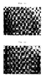
- Fig. 11 (top end surface) and Fig. 12 (bottom end surface) show photomicrographs (15 magnifications) of a section parallel to the end faces of the scaffold corresponding to (12) in Fig. 5 . It is seen that the fibers are accumulated densely like the mesh of a net.
- FIG. 13 and Fig. 14 show photomicrographs of the stained scaffold on the 1st and 12-th days of culture. It is seen that the scaffold on the 12-th day of culture has higher staining density than the scaffold on the 1st day, the stained area reaches a deep portion from the surface of the scaffold, and the growth of a cell and the production of a cartilage matrix proceed well like Example 2.
- the scaffold of the present invention has such high mechanical strength that it can withstand weighted compression in the initial stage of transplantation. Therefore, it can be used in a site which requires mechanical properties, such as a cartilage damaged part. Since the scaffold of the present invention is composed of a biocompatible polymer, it has no bad influence upon a living body.
- the scaffold of the present invention has a certain fiber density, facilitates the intrusion of a cell and enables the supply of oxygen and nutrition and the discharge of carbon dioxide and waste matter to be carried out swiftly. Therefore, the scaffold can grow a cell well.
- the scaffold can be manufactured easily.
- the manufacturing process of the present invention as fibers obtained by the electrospinning method are accumulated on a rotary shaft, accumulated fibers having a uniform accumulation density in the accumulation direction are obtained. Accumulated fibers uniform in a plane parallel to the winding shaft are obtained. Further, certain tension is applied to the fibers by winding up the fibers on the rotary winding shaft, thereby making it possible to obtain high-density accumulated fibers.
- a cell can be grown well.
- a damaged living tissue can be regenerated well.
- the scaffold of the present invention is useful as a cell culture medium in the field of regeneration medicine.
- the scaffold of the present invention is useful as a prosthetic material, especially a prosthetic material for a site in which mechanical properties are important, such as an osteochondral damaged part.
Abstract
(1) the fibers are aligned in a plane direction;
(2) the fibers have a diameter of 0.05 to 50 µm;
(3) the fibers are essentially composed of a biocompatible polymer; and
(4) the scaffold has an apparent density of 95 to 350 kg/m3.
Description
- The present invention relates to a scaffold used for cell growth. The present invention relates to a scaffold which is composed of an assembly of fibers and suitable for use as a prosthetic material or a cell culture medium.
- As an approach to the treatment of a greatly damaged living tissue, active researches into regenerative medicine for the reconstruction of an original living tissue by making use of the differentiation and proliferation of a cell are now under way. When a cell differentiates or grows in vivo, an extracellular matrix serves as a scaffold to construct a tissue. However, when a tissue is greatly damaged, it must be compensated for by an artificial or natural material until the cell itself produces a matrix. That is, a scaffold (prosthetic material) is an important factor for providing the optimum environment for the construction of a tissue. The requirements for this scaffold include 1) bioabsorption, 2) cell adhesion, 3) porosity and 4) mechanical strength. With a view to the creation of a material which satisfies all the above requirements, synthetic polymers (such as polyglycolic acid, polylactic acid and polycaprolactone), natural polymers (such as collagen, gelatin, elastin, hyaluronic acid, alginic acid and chitosan), inorganic materials (such as hydroxylapatite and tricalcium β-phosphate) and composites thereof have been studied up till now.
- As described above, porosity is one of the important requirements for the scaffold (prosthetic material). This is important so as to supply sufficient oxygen and nutrition which are required for the regeneration of a tissue and discharge carbon dioxide or waste materials quickly. Therefore, to attain the porosity of a scaffold, freeze-drying, phase separation and foaming techniques are proposed. As for a structure obtained by the freeze-drying or phase separation technique, the shape of each pore is isolated and the intrusion of a cell is difficult. Thus, the structure is unsatisfactory as a scaffold. A structure obtained by the foaming technique also has a problem that the intrusion of a cell is difficult because pores are isolated independently.
- There is reported nonwoven cloth which is an assembly of fibers made of a thermoplastic polymer and having an average fiber diameter of 0.1 to 2 µm and an average apparent density of 10 to 95 kg/m3, the arbitrary cross section of each fiber being irregular in shape (patent document 1). However, a scaffold which is thicker and stronger is desired.
- There is also proposed a cartilage plug having a porous structure which is formed by preparing a polyurethane polymer containing a water-soluble substance such as saccharose and dissolving the water-soluble substance in a water bath (patent document 2). However, pores formed by this method are not continuous and there is limitation to cell growth.
- It is also proposed to manufacture a scaffold by accumulating nanofibers in a plane by an electrospinning method and use it for the culture of a cell (non-patent document 1). This method has a defect that, when the fibers are accumulated to a predetermined thickness or more, an electrode is covered with the accumulated product as the fibers are collected on a planar collection electrode, whereby it is difficult to maintain a certain potential difference and the density of the accumulated fibers changes in the accumulation direction. The accumulation density of the accumulated product becomes nonuniform in a plane direction perpendicular to the accumulation direction. Therefore, to use this accumulated product as a scaffold for cell growth, the accumulation density must be made uniform to improve mechanical strength.
- (patent document 1)
W02004/88024 - (patent document 2)
JP-A 2004-520855 - (non-patent document 1) Published online 25 March 2002 in Wiley InterScience (www.interscience. wiley.com)
- It is an object of the present invention to provide a scaffold which is a high-density assembly of fibers and suitable for cell growth. It is another object of the present invention to provide a scaffold for cell growth which has excellent mechanical strength. It is still another object of the present invention to provide a scaffold which can grow a cell well. It is a further object of the present invention to provide a process of manufacturing the scaffold. It is a still further object of the present invention to provide a method of growing a cell by using the scaffold. It is a still further object of the present invention to provide a method of regenerating a living tissue by using the scaffold.
- The inventors of the present invention have found that, when fibers are manufactured by an electrospinning method and accumulated on a rotary winding shaft, accumulated fibers having a uniform accumulation density in the accumulation direction are obtained.
- They have also found that, when the fibers are accumulated on the rotary winding shaft, accumulated fibers which are uniform in a plane parallel to the winding shaft is obtained.
- Further, they have found that, when the fibers are wound up on the rotary shaft, certain tension is applied to the fibers and high-density accumulated fibers are obtained.
- They have also found that the obtained accumulated fibers have suitable strength and fiber density as a scaffold for cell growth. The present invention is based on these findings.
- That is, the present invention is a scaffold which is composed of an assembly of fibers and has a 3-D structure consisting of two end faces and a side face, wherein
- (1) the fibers are aligned in a plane direction,
- (2) the fibers have a diameter of 0.05 to 50 µm,
- (3) the fibers are essentially composed of a biocompatible polymer, and
- (4) the scaffold has an apparent density of 95 to 350 kg/m3.
- The present invention is a process of manufacturing a scaffold, comprising the steps of:
- (1) delivering a dope containing a biocompatible polymer into an electrostatic field formed between electrodes from a nozzle to form fibers;
- (2) winding up the obtained fibers on a winding shaft to form a roll of the fibers which are aligned in a plane direction parallel to the winding shaft; and
- (3) cutting out a 3-D structure from the obtained roll.
- The present invention includes a method of dividing or growing a cell by using the scaffold. The present invention also includes a method of regenerating a living tissue by implanting the scaffold in a damaged affected part.
-
-
Fig. 1 shows an example of an apparatus used in an electrospinning method; -
Fig. 2 shows another example of the apparatus used in the electrospinning method; -
Fig. 3 shows still another example of the apparatus used in the electrospinning method; -
Fig. 4 shows a further example of the apparatus used in the electrospinning method; -
Fig. 5 shows a method of cutting out a scaffold in the manufacturing process of the present invention; -
Fig. 6 shows a picture of the top end face of a scaffold obtained in Example 2; -
Fig. 7 shows a picture of the bottom end face of the scaffold obtained in Example 2; -
Fig. 8 shows a picture of the stained scaffold obtained in Example 2 on the 1st day of culture; -
Fig. 9 shows a picture of the stained scaffold obtained in Example 2 on the 12th day of culture; -
Fig. 10 shows a picture of the top end face of a scaffold obtained in Example 3; -
Fig. 11 shows a picture of the bottom end face of the scaffold obtained in Example 3; -
Fig. 12 shows a picture of the section of the scaffold obtained in Example 3; -
Fig. 13 shows a picture of the stained scaffold obtained in Example 3 on the 1st day of culture; and -
Fig. 14 shows a picture of the stained scaffold obtained in Example 3 on the 12th day of culture. -
- 1. nozzle
- 2. dope
- 3. dope holding tank
- 4. positive electrode
- 5. negative electrode
- 6. high-voltage generator
- 7. winder
- 8. static electricity removing apparatus
- 9. winding shaft direction
- 10. scaffold cut out in direction parallel to winding shaft direction
- 11. direction perpendicular to winding direction
- 12. scaffold cut out in direction perpendicular to winding shaft
- The present invention will be described in detail hereinunder
- The scaffold of the present invention has a 3-D structure consisting of two end faces and a side face. The shape of each of the end faces is circular, elliptic, rectangular, etc. The end faces may be curved with irregularities. The two end faces may differ in shape and size. The area of each of the end faces is preferably 0.05 to 8 cm2, more preferably 0.1 to 1 cm2. The side face may be a continuous curved face or may consist of a plurality of faces. That is, the shape of the scaffold of the present invention is preferably a 3-D structure such as a cylinder or a polygonal column.
- The scaffold of the present invention has a 3-D structure, that is, expanses in the transverse direction (x axis), longitudinal direction (y axis) and height direction (z axis). In this respect, it differs from plain nonwoven cloth having expanses in the transverse direction (x axis) and the longitudinal direction (y axis). In the scaffold of the present invention, the term "height direction" refers to a direction perpendicular to one of the end faces.
- The height of the scaffold is preferably 0.5 mm or more, more preferably 2 mm or more. The upper limit of the height is not limited and it can be said that it depends on a site where it is used as a prosthetic material. When the height is smaller than 0.5 mm, the scaffold has low mechanical strength and is not preferred as a prosthetic material for a tissue having high mechanical strength such as a knee joint. The scaffold of the present invention can be used to grow a cell on the surface of a prosthetic material by implanting it in a damaged part of a living body. The scaffold can be provided in a desired form.
- The scaffold of the present invention is composed of an assembly of fibers. In the present invention, the expression "aligned in a plane direction" means that the fibers are aligned substantially parallel to a specific plane. The fibers may be aligned in any one of the transverse, longitudinal and oblique directions as long as they are parallel to this specific plane. The fibers are aligned substantially parallel to the plane shown by broken lines in the cylinder denoted by 10 or 12 in
Fig. 5 . Parts shown by dotted lines in 10 or 12 ofFig. 5 may form concentric curves. The direction of the fibers on the plane is random. - The fibers are preferably aligned in a plane direction parallel to the height direction as shown by 10 in
Fig. 5 . Alternatively, as shown by 12 inFig. 5 , the fibers are preferably aligned in a plane direction perpendicular to the height direction. - The diameter of each of the fibers is 0.05 to 50 µm. When the diameter of the fiber is smaller than 0.05 µm, the strength of the scaffold cannot be maintained disadvantageously. When the diameter of the fiber is larger than 50 µm, the specific surface area of the fiber becomes small and the number of living cells decreases. The diameter of the fiber is preferably 0.2 to 50 µm, more preferably 0.2 to 40 µm. The diameter of the fiber can be obtained by observing the scaffold through, for example, a scanning electron microscope (about 200 magnifications).
- The arbitrary cross section of the fiber may be substantially spherical or irregular. When the arbitrary cross section of the fiber is irregular, the specific surface area of the fiber increases, whereby the area of the surface of the fiber to which a cell adheres becomes sufficiently large at the time of culture.
- The expression "the arbitrary cross section of the fiber is irregular" means that the arbitrary cross section of the fiber has any shape other than a substantially spherical shape and includes a case where the surface of the fiber is roughened to have depressions and/or projections uniformly.
- The irregular shape is preferably at least one shape selected from the group consisting of fine depressions on the surface of the fiber, fine projections on the surface of the fiber, depressions formed linearly in the fiber axial direction on the surface of the fiber, projections formed linearly in the fiber axial direction on the surface of the fiber and fine pores on the surface of the fiber. They may be formed alone or in combination. The above "fine depressions" and "fine projections" mean that 0.1 to 1 µm depressions and projections are formed on the surface of the fiber, respectively, and the "fine pores" means that pores having a diameter of 0.1 to 1 µm are existent on the surface of the fiber. The expression "depressions and/or projections formed linearly" means that ribs having a width of 0.1 to 1 µm are formed in the fiber axial direction.
- The apparent density of the scaffold is 95 to 350 kg/m3, preferably 100 to 300 kg/m3, more preferably 100 to 250 kg/m3. When the apparent density is lower than 95 kg/m3, mechanical strength becomes low though the intrusion of a cell is satisfactory. When the apparent density is higher than 350 kg/m3, the intrusion of a cell becomes difficult, which is not preferred as a scaffold. The apparent density can be calculated by measuring the volume (area x height) and mass of the obtained assembly.
- When the scaffold is used for implantation, mechanical strength high enough to withstand weighted compression in the initial stage of transplantation is required. Shape stability to compression can be provided by aligning the fibers of the scaffold of the present invention in the weighted compression direction. The compressive elastic modulus of the scaffold of the present invention is preferably 0.5 to 5 MPa, more preferably 1.5 to 5 MPa.
- The porosity of the scaffold of the present invention is preferably 75 to 90 %, more preferably 78 to 88 %. The porosity is obtained by subtracting the volume of a polymer from the volume of a porous material.
- The fibers constituting the scaffold of the present invention are essentially composed of a biocompatible polymer. Each of the fibers comprises a recurring unit derived from a biocompatible monomer in an amount of preferably 80 to 100 mol%, more preferably 90 to 100 mol% of the total of all the recurring units. Examples of the biocompatible monomer include glycolic acid, lactic acid, caprolactones and dioxanones. A blend of biocompatible polymers may also be used.
- The biocompatible polymer is preferably a bioabsorbable polymer. The bioabsorbable polymer is preferably essentially composed of an aliphatic polyester. Examples of the aliphatic polyester include polyglycolic acid, polylactic acid, polycaprolactone, polydioxanone, polytrimethylene carbonate, polybutylene succinate, polyethylene succinate and copolymers thereof. Out of these, the aliphatic polyester is preferably at least one selected from the group consisting of polyglycolic acid, polylactic acid, polycaprolactone and copolymers thereof. A copolymer of lactic acid and glycolic acid is particularly preferred. The copolymerization ratio of the former to the latter (mol) is preferably 20/80 to 80/20, more preferably 40/60 to 75/25.
- Besides the bioabsorbable polymers, biocompatible polymers such as polyester, nylon, polysulfone, polyurethane, polyethylene, polypropylene, methyl poly(methacrylate), poly(hydroxyethyl methacrylate), poly(vinyl chloride) and polysiloxane may be used as the polymer constituting the porous material.
- The intrinsic viscosity of the biocompatible polymer is 0.1 to 1.4 dL/g, preferably 0.04 to 1.3 dL/g, more preferably 0.6 to 1.2 dL/g (30°C, hexafluoroisopropanol).
- The scaffold of the present invention may further contain a second component except the biocompatible polymer. The component is preferably at least one selected from the group consisting of cell growth factors such as phospholipids, carbohydrates, glycolipids, steroids, polyamino acids, proteins, polyoxyalkylenes, FGF (fiber blast cell growth factors), EGF (epidermal growth factors), PDGF (platelet-derived growth factors), TGF-β (β type transforming growth factors), NGF (nerve growth factors), HGF (hepatic cell growth factors) and BMP (bone morphogenetic factors). Specific examples of the second component include phospolipids such as phosphatidylcholine, phosphatidylethanolamine, phosphatidylserine and phosphatidylglycerol, and/or carbohydrates such as polygalacturonic acid, heparin, chondroitin sulfate, hyaluronic acid, dermatan sulfate, chondroitin, dextran sulfate, sulfated cellulose, alginic acid, dextran, carboxymethyl chitin, galactomannann, gum Arabic, traganth gum, gellan gum, sulfated gellan, karaya gum, carrageenan, agar, xanthan gum, curdlan, pullulan, cellulose, starch, carboxymethyl cellulose, methyl cellulose, glucomannan, chitin, chitosan, xyloglucan and lenthinan, and/or glucolipids such as galactocerebroside, glucocerebroside, globoside, lactosylceramide, trihexosylceramide, paragloboside, galactosyldiacylglycerol, sulfoquinobosyldiacylglycerol, phosphatidylinositol and glycosylpolyprenol phosphate, and/or steroids such as cholesterols, cholic acid, sapogenin and digitoxin, and/or polyamino acids such as polyaspartic acid, polyglutamic acid and polylysine, and/or proteins such as collagens, gelatin, fibronectin, fibrin, laminin, casein, keratin, sericin and thrombin, and/or polyoxyalkylenes such as polyoxyethylene alkyl ether, polyoxyethylene propylene alkyl ether, polyoxyethylene sorbitan ether. The preferred content of the second component is 0.01 to 50 parts by weight based on 100 parts by weight of the biocompatible polymer.
- The scaffold of the present invention can be manufactured through first to third steps.
- The first step is a so-called "electrospinning method". The first step is to form fibers by delivering a dope containing a biocompatible polymer into an electrostatic field formed between electrodes from a nozzle.
- The electrostatic field is formed between a pair of electrodes or among a plurality of electrodes. The electrodes may be made of a metal, inorganic or organic material as long as they show conductivity. Also they may have a conductive metal, inorganic or organic thin film on an insulating material. High voltage may be applied to any one of the above electrodes. The present invention includes a case where two high-voltage electrodes which differ from each other in voltage value (for example, 15 kV and 10 kV) and one electrode connected to an earth are used and a case where more than 3 electrodes are used. Preferably, one of the electrodes is a nozzle and the other electrode is a collection electrode.
- The distance between the electrodes which depends on the amount of charge, the size of the nozzle, the flow rate of a spinning liquid and the concentration of the spinning liquid is suitably 5 to 20 cm at 10 kV. The potential of static electricity to be applied is preferably 3 to 100 kV, more preferably 5 to 50 kV, much more preferably 5 to 30 kV.
- The dope contains a biocompatible polymer and a solvent. The biocompatible polymer has already been described above. The content of the biocompatible polymer in the dope is preferably 1 to 30 wt%, more preferably 2 to 20 wt%. When the content of the biocompatible polymer is lower than 1 wt%, it is difficult to form fibers disadvantageously. When the content is higher than 30 wt%, the diameter of the obtained fibers becomes too large disadvantageously.
- The solvent is preferably a substance which dissolves the biocompatible polymer, has a boiling point of 200°C or lower at normal pressure and is liquid at room temperature. Examples of the solvent include methylene chloride, chloroform, acetone, methanol, ethanol, propanol, isopropanol, toluene, tetrahydrofuran, 1,1,1,3,3,3-hexafluoroisopropanol, water, 1,4-dioxane, carbon tetrachloride, cyclohexane, cyclohexanone, N,N-dimethylformamide and acetonitrile. Out of these, methylene chloride, chloroform and acetone are particularly preferred from the viewpoints of the solubility of a biocompatible polymer, especially an aliphatic polyester. These solvents may be used alone or in combination. In the present invention, another solvent may be used in limits not prejudicial to the object of the present invention.
- The diameter of the nozzle is preferably 0.6 to 1.5 mm. When the dope is supplied into the electrostatic field from the nozzle, a plurality of nozzles may be used to increase the production rate of a fibrous material.
- Delivery may be carried out by extruding the dope with a syringe having a piston like an injector. A tube having a nozzle at the end may also be used. In this case, the dope is drawn by the potential difference of static electricity to be spun toward the electrode. The fibers may be in a state that the solvent is distilled off or in a state that the solvent is still contained.
- A static electricity removing apparatus is preferably used between the nozzle and the electrode. The static electricity removing apparatus is an apparatus which applies an ion air to the fibers to keep ion balance uniform and disperses the fibers into air by easing the charged state of the fibers before they reaches the electrode. The thickness of a roll can be increased by using this apparatus. A scaffold having a large diameter can be obtained by increasing the thickness of the roll.
- The second step is to wind up the obtained fibers on a rotary winding shaft and accumulate them so as to obtain a roll in which the fibers are aligned in a plane parallel to the winding shaft.
- The fibers are accumulated around the winding shaft of a winder between the nozzle and the collection electrode. The shape of the winding shaft may be columnar or prismatic.
- Since the average apparent density of the scaffold depends on the revolution of the winding shaft, a scaffold having a desired average apparent density can be obtained by controlling the revolution of the winding shaft. Stated more specifically, when the revolution is high, the average apparent density of the obtained scaffold is high. When the revolution is low, the average apparent density of the obtained scaffold is low. The revolution of the winding shaft is preferably 1 to 1,000 rpm, more preferably 5 to 200 rpm.
- The obtained roll is substantially aligned in a plane parallel to the winding shaft. The shape of the roll is arbitrary such as columnar or spindle-like.
- After the second step, the obtained roll is preferably heated. The heating temperature is preferably 40 to 90°C. By heating, the fibers are thermally fused to one another, thereby making it possible to obtain a scaffold having excellent compressive strength.
- The first step and the second step will be explained with reference to
Figs. 1 to 4 .Fig. 1 shows an example using a syringe andFig. 2 shows an example using a tubular discharger. InFig. 1 , the dope (2) is charged into the dope holding tank (3) of a syringe having a nozzle (1). Voltage is applied to the nozzle (1) by a high voltage generator (6) and an electrostatic field is formed between a positive electrode (4) and a negative electrode (5). When the dope (2) is extruded from the nozzle (1), the charged dope is moved toward the negative electrode (5) through the electrostatic field to form fibers. - The fibers can be formed by the method shown in
Fig. 2 . The dope (2) is charged into the dope holder tank (3) of a tubular discharger having a nozzle (1). A positive electrode (4) is inserted into the dope holding tank (3) and voltage is applied to the nozzle by the high-voltage generator (6) to form an electrostatic field between the positive electrode (4) and the negative electrode (5). The charged dope is discharged from the nozzle (1) by adjusting the distance between the nozzle (1) at the end of the discharger and the negative electrode (5) and moved toward the negative electrode (5) through the electrostatic field to form fibers. The fibers are wound up by the winder (7) before the negative electrode (5). - In the present invention, while the dope (2) is spun toward the negative electrode (5), the solvent is evaporated and the fibers are formed. Although the solvent evaporates completely at normal room temperature while the fibers are collected to the winder (7), if the evaporation of the solvent is incomplete, the dope may be spun under reduced pressure. The spinning temperature depends on the evaporation behavior of the solvent and the viscosity of a spinning liquid but is generally 0 to 50°C.
-
Fig. 3 and Fig. 4 show examples in which a static electricity removing apparatus (8) is installed. The static electricity removing apparatus (8) is installed between the nozzle (1) and the negative electrode (5) to carry out spinning so that the fibers can be collected to the winder (7). - The third step is to cut out a 3-D structure from the obtained roll. The 3-D structure can be bored out by using a cylindrical borer as shown in
Fig. 5 . InFig. 5 , the 3-D structure is preferably bored out (10) such that the height direction of the 3-D structure becomes parallel to the aligning direction of the fibers. Also, the 3-D structure is preferably bored out (12) such that the height direction of the 3-D structure becomes perpendicular to the aligning direction of the fibers. The scaffold (10) is superior in compressive strength to the scaffold (12). - A cell can be differentiated and grown by using the scaffold of the present invention. The differentiation and growth of a cell may be carried out in vitro or in vivo. In vitro, the scaffold may be used as a culture medium for differentiating and growing a cell. In vivo, the scaffold of the present invention may be used as a prosthetic material. Particularly, a living tissue can be regenerated by burying the scaffold of the present invention in a damaged affected part. Alternatively, the scaffold of the present invention having a cultured cell in vitro may be buried in an affected part as a prosthetic material. The living tissue is, for example, an osteochondral tissue.
- Materials and measuring methods used in Examples are given below.
- (1) Lactic acid-glycolic acid copolymer; LACTEL (DL lactic acid/glycolic acid copolymer, molar ratio = 50/50, intrinsic viscosity: 1.05 dL/g, 30°C, hexafluoroisopropanol, manufactured by Absorbable Polymers International Co., Ltd.)
- (2) Methylene chloride, ethanol, formaldehyde; manufactured by Wako Pure Chemical Industries, Ltd.
- (3) Rat mesenchymal stem cell; manufactured by Dainippon Sumitomo Pharmaceuticals, Ltd.
- (4) MEM (Minimum Essential Medium), FBS(Fetal Bovine Serum), PBS (Phosphate-buffered Saline), antibiotic-antimycotic, 0.05 % Trypsin-EDTA solution; manufactured by Invitrogen Co., Ltd.
- (5) L-ascorbic acid 2-phosphate magnesium salts n-hydrate (water content of 26.7 %), β-glycerophosphate disodium n-hydrate, Dexamethason, Triton X-100, Toluidine Blue; manufactured by Sigma Co., Ltd.
- (6) Pico Green (registered trademark) ds DNA Quantitation Kit; manufactured by Molecular Probe Co., Ltd.
- A lactic acid-glycolic acid copolymer (molar ratio= 50/50) was dissolved in a mixed solvent of methylene chloride and ethanol to prepare a 15 wt% dope.
- A cylindrical roll composed of an assembly of fibers was obtained by the electrospinning method using the apparatus shown in
Fig. 4 . The inner diameter of the nozzle (1) was 1.3 mm. The distance from the nozzle (1) to the winder (7) was 20 cm, and the distance from the nozzle (1) to the static electricity removing apparatus (8) was 35 cm. Applied voltage was 15 kV. The winder (7) and the static electricity removing apparatus (8) manufactured by Kasuga Denki Co., Ltd. were installed between the nozzle (1) and the negative electrode (5). The positive electrode (4) was inserted into the dope holding tank (3). The revolution of the winder (7) was set to 100 rpm. - The dope was fed to the dope holding tank (3), the distance between the nozzle (1) and the negative electrode (5) was adjusted, and fibers were delivered from the nozzle (1). Delivery was continued for 120 minutes, and the fibers were wound up by the rotating winder (7) to obtain a cylindrical roll. The roll was put into a thermostatic device and heated at 80°C for 10 minutes.
- A cylindrical scaffold having a diameter of 5 mm and a height of 5 mm denoted by 10 in
Fig. 5 was cut out from the obtained roll by using a biopsy trepan (manufactured by Kai Industries, Ltd.) as shown inFig. 5 . - The characteristic properties of the obtained scaffold were measured by the following methods. The results are shown in Table 1.
- (1) diameter of fiber
The diameter of each fiber was observed visually through a digital microscope (VHX Digital Microscope of Keyence Co., Ltd.) or a scanning electron microscope (manufactured by JEOL Ltd., 200 magnifications).Arbitrary 10 fibers were selected from each view field in electron microscopic observation and measured, and this operation was carried out for 5 view fields to calculate the average value of 50 fibers. Massive foreign matter or a bundle of fibers fused to one another produced in the step of forming fibers were not measured. - (2) apparent density of scaffold
The apparent density of the scaffold was calculated from the following equation.
(p: apparent density of porous material, m: mass, d: diameter, h: height) - (3) porosity of scaffold
The porosity of the scaffold was calculated from the following equation.
(ε: porosity of scaffold, p: apparent density of porous material, ρ0: intrinsic density of polymer) - (4) compressive strength
The compressive strength of the scaffold corresponding to (10) inFig. 5 was measured in accordance with JISK 7220. That is, the scaffold in which fibers were aligned parallel to the height direction of the cylinder was measured. A test specimen was placed between the pressure planes of a material tester, the center line of the specimen was aligned with the center lines of the pressure planes, and it was confirmed that the upper and lower surfaces of the specimen were parallel to the pressure planes. A load was applied to the test specimen at a constant test speed of 10 mm/min to measure compressive strength until a compression limit was reached. - The same lactic acid-glycolic acid copolymer as in Example 1 was used to prepare a 10 wt% dope.
- A cylindrical roll composed of an assembly of fibers was obtained in the same manner as in Example 1 except that the delivery time was set to 90 minutes and the heat treatment was carried out at 70°C for 10 minutes.
- A cylindrical scaffold having a diameter of 5 mm and a height of 5 mm corresponding to 10 in
Fig. 5 was cut out from the obtained roll in the same manner as in Example 1.Fig. 6 (top end face) andFig. 7 (bottom end face) show microphotographs (15 magnifications) of a section parallel to the end faces of the scaffold corresponding to 10 inFig. 5 . It is seen that the fibers were accumulated in layers. - The characteristics properties of the scaffold were evaluated in the same manner as in Example 1. The results are shown in Table 1.
- The biological evaluation of the scaffold was carried out by the following method. The mesenchymal stem cell of a rat was cultured in MEM containing 15 % of FBS and 1 % of antibiotic-antimycotic at 37°C in a 5 % CO2 atmosphere for 3 passages.
- The prepared rat mesenchymal stem cells were seeded in the obtained scaffold at a density of 6.0 x 10⁶/cm3 and cultured in MEM containing 15 % of FBS, 1 % of antibiotic-antimycotic, 10 µM of dexamethasone, 50 µM of L-ascorbic acid 2-phosphate magnesium salts n-hydrate and 10 mM of β-glycerophosphate disodium n-hydrate at 37°C in a 5 % CO2 incubator for 12 days. The culture medium was exchanged 3 times a week.
- The scaffold was taken out on the first day, sixth day and 12-th day of culture to measure the amount of DNA and evaluate it histologically.
- (1) Amount of DNA
The amount of DNA was measured based on the measurement manual of Pico Green (registered trademark) ds DNA Quantitation Kit. The sample to be measured was frozen and molten with 0.2 % of Triton-X100 three times and ground with supersonic waves to obtain a cell suspension, and an extract was prepared from the suspension. 100 µl of the measured sample treated with enzyme was put into a micro-plate with 96 holes, and 100 µl of Pico Green (registered trademark) ds DNA Quantitation Reagent diluted with TE (pH of 7.5) 200 times was added to the sample to measure the amount of DNA with 485 nm excitation light and 535 nm fluorescence. A calibration curve was drawn from the value of a standard DNA solution and the amount of DNA of the measurement sample was calculated based on the curve. The result is shown in Table 2. The amount of DNA is proportional to the number of grown cells. - (2) Histological evaluation
For histological evaluation, the scaffold was immersed in 10 % of formaldehyde before sampling. Before it was stained, it was cleaned with distilled water, immersed in 100 % of ethanol for 1 hour twice, 90 % of ethanol for 1 hour and 70 % of ethanol for 1 hour to be cleaned while it was diluted stepwise. The obtained scaffold was immersed in distilled water for 15 minutes to be cleaned and then in a 0.4 % toluidine blue-aqueous solution for 1 minute. Thereafter, it was cleaned in running water for 1 minute to remove excess of a staining solution and observed through a digital microscope at 450 magnifications. - (3) Result
- The measurement result of the amount of DNA is shown in Table 2.
Fig. 8 andFig. 9 show photomicrographs of the stained scaffold on the 1st and 12-th days of culture. It is seen that the scaffold on the 12-th day of culture has higher staining density than the scaffold on the 1st day, the stained area reaches a deep portion of the scaffold, and the growth of the cell and the production of a cartilage matrix proceed well. - The operation of Example 2 was repeated to obtain a cylindrical scaffold having a diameter of 5 mm and a height of 5 mm corresponding to 12 in
Fig. 5 . The measurement results of the characteristic properties of the scaffold are shown in Table 1. -
Fig. 10 shows a photomicrograph (200 magnifications) of a section perpendicular to the end surface of the scaffold corresponding to 12 inFig. 5 . It is seen that the fibers are aligned in a plane direction.Fig. 11 (top end surface) andFig. 12 (bottom end surface) show photomicrographs (15 magnifications) of a section parallel to the end faces of the scaffold corresponding to (12) inFig. 5 . It is seen that the fibers are accumulated densely like the mesh of a net. - A cell was cultured in the same manner as in Example 2 except that the obtained scaffold was used to measure the amount of DNA. The result is shown in Table 2.
Fig. 13 and Fig. 14 show photomicrographs of the stained scaffold on the 1st and 12-th days of culture. It is seen that the scaffold on the 12-th day of culture has higher staining density than the scaffold on the 1st day, the stained area reaches a deep portion from the surface of the scaffold, and the growth of a cell and the production of a cartilage matrix proceed well like Example 2.Table 1 Spinning conditions Diameter of fiber (µm) Apparent density (kg/m3) Porosity (%) Compressive strength Revolution (rpm)*1 Time (min) Compressive elastic modulus (MPa) 10 % displacement stress (MPa) Example 1 100 120 5 220 83.5 2.61 0.99 Example 2 100 90 4.6 214 83.7 4.58 0.12 Example 3 100 90 7.8 224 82.0 1.34 0.01 *1: revolution of winder (rpm) Table 2 Time change in amount of DNA (µg/scaffold) Example 2 Example 3 1st day of culture 0.93 0.89 6-th day of culture 1.02 1.06 12-th day of culture 1.09 0.87 - The scaffold of the present invention has such high mechanical strength that it can withstand weighted compression in the initial stage of transplantation. Therefore, it can be used in a site which requires mechanical properties, such as a cartilage damaged part. Since the scaffold of the present invention is composed of a biocompatible polymer, it has no bad influence upon a living body. The scaffold of the present invention has a certain fiber density, facilitates the intrusion of a cell and enables the supply of oxygen and nutrition and the discharge of carbon dioxide and waste matter to be carried out swiftly. Therefore, the scaffold can grow a cell well.
- According to the manufacturing process of the present invention, the scaffold can be manufactured easily. According to the manufacturing process of the present invention, as fibers obtained by the electrospinning method are accumulated on a rotary shaft, accumulated fibers having a uniform accumulation density in the accumulation direction are obtained. Accumulated fibers uniform in a plane parallel to the winding shaft are obtained. Further, certain tension is applied to the fibers by winding up the fibers on the rotary winding shaft, thereby making it possible to obtain high-density accumulated fibers.
- According to the cell growing method of the present invention, a cell can be grown well. According to the living tissue regeneration method of the present invention, a damaged living tissue can be regenerated well.
- The scaffold of the present invention is useful as a cell culture medium in the field of regeneration medicine. The scaffold of the present invention is useful as a prosthetic material, especially a prosthetic material for a site in which mechanical properties are important, such as an osteochondral damaged part.
Claims (18)
- A scaffold composed of an assembly of fibers and having a 3-D structure consisting of two end faces and a side face, wherein(1) the fibers are aligned in a plane direction;(2) the fibers have a diameter of 0.05 to 50 µm;(3) the fibers are essentially composed of a biocompatible polymer; and(4) the scaffold has an apparent density of 95 to 350 kg/m3.
- The scaffold according to claim 1, wherein the fibers are aligned in a plane direction parallel to the height direction.
- The scaffold according to claim 1, wherein the fibers are aligned in a plane direction perpendicular to the height direction.
- The scaffold according to claim 1, wherein the fibers have a diameter of 0.2 to 40 µm.
- The scaffold according to claim 1, which has an apparent density of 100 to 250 kg/m3.
- The scaffold according to claim 1, which has a porosity of 75 to 90 %.
- The scaffold according to claim 1, which has a height of 0.5 mm or more.
- The scaffold according to claim 1, which has an end face area of 0.05 to 8 cm2.
- The scaffold according to claim 1, which is cylindrical or polygonal column-like.
- The scaffold according to claim 1, which has a compressive elastic modulus in the height direction of 0.5 to 5 MPa.
- The scaffold according to claim 1, wherein the biocompatible polymer is bioabsorbable.
- The scaffold according to claim 1, wherein the biocompatible polymer is an aliphatic polyester.
- The scaffold according to claim 1, wherein the aliphatic polyester is at least one selected from the group consisting of polyglycolic acid, polylactic acid, polycaprolactone and copolymers thereof.
- The scaffold according to claim 1, which is a prosthetic material or a cell culture medium.
- A process of manufacturing the scaffold of any one of claims 1 to 12, comprising the steps of:(1) delivering a dope containing a biocompatible polymer into an electrostatic field formed between electrodes from a nozzle to form fibers;(2) winding up the obtained fibers on a winding shaft to form a roll in which the fibers are aligned in a plane direction parallel to the winding shaft; and(3) cutting out a 3-D structure from the obtained roll.
- The manufacturing process according to claim 14,
wherein the fibers are formed by using a static electricity removing apparatus. - A method of differentiating and growing a cell by using the scaffold of claim 1.
- A method of regenerating a living tissue by burying the scaffold of claim 1 into a damaged affected part.
Applications Claiming Priority (2)
| Application Number | Priority Date | Filing Date | Title |
|---|---|---|---|
| JP2006059393 | 2006-03-06 | ||
| PCT/JP2007/054739 WO2007102606A1 (en) | 2006-03-06 | 2007-03-05 | Scaffold material |
Publications (2)
| Publication Number | Publication Date |
|---|---|
| EP1994949A1 true EP1994949A1 (en) | 2008-11-26 |
| EP1994949A4 EP1994949A4 (en) | 2012-07-18 |
Family
ID=38475025
Family Applications (1)
| Application Number | Title | Priority Date | Filing Date |
|---|---|---|---|
| EP07738224A Withdrawn EP1994949A4 (en) | 2006-03-06 | 2007-03-05 | Scaffold material |
Country Status (8)
| Country | Link |
|---|---|
| US (1) | US20090076530A1 (en) |
| EP (1) | EP1994949A4 (en) |
| JP (1) | JP5119144B2 (en) |
| KR (1) | KR20080107405A (en) |
| CN (1) | CN101443053A (en) |
| AU (1) | AU2007222949B2 (en) |
| CA (1) | CA2645541A1 (en) |
| WO (1) | WO2007102606A1 (en) |
Cited By (2)
| Publication number | Priority date | Publication date | Assignee | Title |
|---|---|---|---|---|
| WO2013165975A1 (en) * | 2012-04-30 | 2013-11-07 | The Johns Hopkins University | Electro-mechanically stretched micro fibers and methods of use thereof |
| US11779682B2 (en) | 2012-04-30 | 2023-10-10 | The Johns Hopkins University | Electro-mechanically stretched micro fibers and methods of use thereof |
Families Citing this family (26)
| Publication number | Priority date | Publication date | Assignee | Title |
|---|---|---|---|---|
| US9345486B2 (en) * | 2009-03-16 | 2016-05-24 | University Of Washington | Nanofibrous conduits for nerve regeneration |
| JP5531359B2 (en) * | 2009-12-15 | 2014-06-25 | HOYA Technosurgical株式会社 | Cell culture carrier and method for producing cell culture carrier |
| JP5896612B2 (en) * | 2011-03-17 | 2016-03-30 | サンスター株式会社 | Cell scaffold material |
| JP5846550B2 (en) * | 2011-05-02 | 2016-01-20 | 国立研究開発法人物質・材料研究機構 | Short fiber scaffold material, short fiber-cell composite aggregate preparation method and short fiber-cell composite aggregate |
| JP2014525279A (en) | 2011-08-12 | 2014-09-29 | カーディアック ペースメイカーズ, インコーポレイテッド | Method for coating devices using electrospinning and meltblowing methods |
| ES2833280T3 (en) | 2012-01-13 | 2021-06-14 | Massachusetts Gen Hospital | Isolated human lung progenitor cells and their uses |
| WO2015066526A1 (en) * | 2013-10-31 | 2015-05-07 | The Johns Hopkins University | Elecrostretched polymer microfibers for microvasculature development |
| US11369465B2 (en) | 2013-01-14 | 2022-06-28 | Scripps Health | Tissue array printing |
| US20150025608A1 (en) | 2013-07-22 | 2015-01-22 | Cardiac Pacemakers, Inc. | Lubricious, biocompatible hydrophilic thermoset coating using interpenetrating hydrogel networks |
| TWI649376B (en) | 2013-08-30 | 2019-02-01 | 日產化學工業有限公司 | Composition for forming fibers and suitable material for living organism using the same |
| EP3085817A4 (en) | 2013-12-20 | 2017-08-02 | Nissan Chemical Industries, Ltd. | Fibers, composition for producing fibers, and biomaterial containing fibers |
| US10240122B2 (en) | 2014-02-14 | 2019-03-26 | Nissan Chemical Industries, Ltd. | Active-ester-group-containing composition for producing fibers, and cell culture scaffold material using fibers produced from active-ester-group-containing composition |
| WO2015138970A1 (en) | 2014-03-14 | 2015-09-17 | Scripps Health | Electrospinning of cartilage and meniscus matrix polymers |
| CA2979982A1 (en) * | 2015-03-17 | 2016-09-22 | President And Fellows Of Harvard College | Automated membrane fabrication system |
| US9855415B2 (en) | 2015-07-25 | 2018-01-02 | Cardiac Pacemakers, Inc. | Medical electrical lead with biostable PVDF-based materials |
| CN105963753A (en) * | 2016-06-16 | 2016-09-28 | 湖州科达化工燃料有限公司 | Anti-infection medical film |
| BE1024733B1 (en) | 2016-11-09 | 2018-06-14 | Univercells Sa | CELL GROWTH MATRIX |
| CN110325224B (en) | 2016-12-27 | 2023-01-31 | 波士顿科学国际有限公司 | Degradable scaffold for electrospinning |
| US20180222145A1 (en) * | 2017-02-07 | 2018-08-09 | Kabushiki Kaisha Toshiba | Fiber-oriented material and method for manufacturing the same |
| WO2019079681A1 (en) * | 2017-10-20 | 2019-04-25 | President And Fellows Of Harvard College | Methods for producing mature adipocytes and methods of use thereof |
| US20200248122A1 (en) | 2019-02-05 | 2020-08-06 | Corning Incorporated | Packed-bed bioreactor systems and methods of using the same |
| US20220228096A1 (en) * | 2019-06-27 | 2022-07-21 | Showa Denko Materials Co., Ltd. | Cell Scaffold Material, Cell Culture Support, and Cell Culture Method |
| US11118151B2 (en) | 2019-11-05 | 2021-09-14 | Corning Incorporated | Fixed bed bioreactor and methods of using the same |
| CN111603608B (en) * | 2020-05-15 | 2021-12-10 | 南通大学 | Pullulan-hyaluronic acid-microfiber spinal cord scaffold and preparation method thereof |
| CN113913805B (en) * | 2021-10-20 | 2023-08-22 | 中南大学湘雅医院 | Cold spraying modified layer and application thereof |
| CN114949353B (en) * | 2022-01-24 | 2023-05-30 | 东华大学 | Biological function differentiated adaptive musculoskeletal system prosthesis and preparation method thereof |
Citations (1)
| Publication number | Priority date | Publication date | Assignee | Title |
|---|---|---|---|---|
| US20040001877A1 (en) * | 1999-04-14 | 2004-01-01 | Shu-Tung Li | Biopolymeric membrane for meningeal tissue repair |
Family Cites Families (5)
| Publication number | Priority date | Publication date | Assignee | Title |
|---|---|---|---|---|
| GB1527592A (en) * | 1974-08-05 | 1978-10-04 | Ici Ltd | Wound dressing |
| US5681353A (en) * | 1987-07-20 | 1997-10-28 | Regen Biologics, Inc. | Meniscal augmentation device |
| ATE412383T1 (en) * | 1997-05-30 | 2008-11-15 | Osteobiologics Inc | FIBER REINFORCED POROUS BIODEGRADABLE IMPLANT DEVICE |
| US6626945B2 (en) | 2000-03-14 | 2003-09-30 | Chondrosite, Llc | Cartilage repair plug |
| TW200427889A (en) * | 2003-03-31 | 2004-12-16 | Teijin Ltd | Non-woven fabric and process for producing the same |
-
2007
- 2007-03-05 EP EP07738224A patent/EP1994949A4/en not_active Withdrawn
- 2007-03-05 US US12/281,923 patent/US20090076530A1/en not_active Abandoned
- 2007-03-05 CN CNA2007800164616A patent/CN101443053A/en active Pending
- 2007-03-05 KR KR1020087021755A patent/KR20080107405A/en not_active Application Discontinuation
- 2007-03-05 WO PCT/JP2007/054739 patent/WO2007102606A1/en active Application Filing
- 2007-03-05 JP JP2008503918A patent/JP5119144B2/en active Active
- 2007-03-05 AU AU2007222949A patent/AU2007222949B2/en not_active Ceased
- 2007-03-05 CA CA002645541A patent/CA2645541A1/en not_active Abandoned
Patent Citations (1)
| Publication number | Priority date | Publication date | Assignee | Title |
|---|---|---|---|---|
| US20040001877A1 (en) * | 1999-04-14 | 2004-01-01 | Shu-Tung Li | Biopolymeric membrane for meningeal tissue repair |
Non-Patent Citations (2)
| Title |
|---|
| See also references of WO2007102606A1 * |
| TEO W E ET AL: "Porous tubular structures with controlled fibre orientation using a modified electrospinning method; Tubular structures with controlled fibre orientation through electrospinning", NANOTECHNOLOGY, IOP, BRISTOL, GB, vol. 16, no. 6, 1 June 2005 (2005-06-01), pages 918-924, XP020091106, ISSN: 0957-4484, DOI: 10.1088/0957-4484/16/6/049 * |
Cited By (3)
| Publication number | Priority date | Publication date | Assignee | Title |
|---|---|---|---|---|
| WO2013165975A1 (en) * | 2012-04-30 | 2013-11-07 | The Johns Hopkins University | Electro-mechanically stretched micro fibers and methods of use thereof |
| US10119202B2 (en) | 2012-04-30 | 2018-11-06 | The Johns Hopkins University | Method for preparing electro-mechanically stretched hydrogel micro fibers |
| US11779682B2 (en) | 2012-04-30 | 2023-10-10 | The Johns Hopkins University | Electro-mechanically stretched micro fibers and methods of use thereof |
Also Published As
| Publication number | Publication date |
|---|---|
| JP5119144B2 (en) | 2013-01-16 |
| KR20080107405A (en) | 2008-12-10 |
| AU2007222949B2 (en) | 2011-04-21 |
| EP1994949A4 (en) | 2012-07-18 |
| CN101443053A (en) | 2009-05-27 |
| CA2645541A1 (en) | 2007-09-13 |
| WO2007102606A1 (en) | 2007-09-13 |
| JPWO2007102606A1 (en) | 2009-07-23 |
| AU2007222949A1 (en) | 2007-09-13 |
| US20090076530A1 (en) | 2009-03-19 |
Similar Documents
| Publication | Publication Date | Title |
|---|---|---|
| EP1994949A1 (en) | Scaffold material | |
| EP1815820A1 (en) | Cylindrical member and process for producing the same | |
| Zhang et al. | Electrospun PDLLA/PLGA composite membranes for potential application in guided tissue regeneration | |
| Deng et al. | Biomimetic structures: biological implications of dipeptide‐substituted polyphosphazene–polyester blend nanofiber matrices for load‐bearing bone regeneration | |
| Moroni et al. | 3D fiber‐deposited electrospun integrated scaffolds enhance cartilage tissue formation | |
| EP1851858B1 (en) | Substrate recognition by differentiable human mesenchymal stem cells | |
| Chen et al. | Preparation and characterization of coaxial electrospun thermoplastic polyurethane/collagen compound nanofibers for tissue engineering applications | |
| JP4481994B2 (en) | Bioabsorbable porous material | |
| Tan et al. | Electrospun vein grafts with high cell infiltration for vascular tissue engineering | |
| Bhattarai et al. | Hydrophilic nanofibrous structure of polylactide; fabrication and cell affinity | |
| Skotak et al. | Improved cellular infiltration into nanofibrous electrospun cross-linked gelatin scaffolds templated with micrometer-sized polyethylene glycol fibers | |
| Lin et al. | Aligned 3D porous polyurethane scaffolds for biological anisotropic tissue regeneration | |
| JP5010854B2 (en) | Revascularization material | |
| JP4354996B2 (en) | Fiber structure containing phospholipids | |
| Ding et al. | Establishment of 3D culture and induction of osteogenic differentiation of pre-osteoblasts using wet-collected aligned scaffolds | |
| JP4988221B2 (en) | Composite material | |
| EP2291556A2 (en) | Nonwoven structure and method of fabricating the same | |
| Wojasiński et al. | Electrospinning production of PLLA fibrous scaffolds for tissue engineering | |
| Stodolak-Zych et al. | The membrane with polylactide and hyaluronic fibers for skin substitute | |
| JP5038639B2 (en) | Cultured artificial bone | |
| US20230002935A1 (en) | Electrospinning collector for the production of three-dimensional electrospun constructs | |
| Avci | The Effect of Fiber Diameter on the Degradation Profile, Elastic Modulus, Yield Strength and Hydrophilicity of Electrospun PCL/gelatin Tissue Engineering Scaffolds | |
| Ndreu | Electrospun nanofibrous scaffolds for tissue engineering | |
| Moghe et al. | Hybrid nanofiber structures for tissue engineering. | |
| Nowlin | Electrospinning nanofiber scaffolds with alignment gradient and three-dimensional structure |
Legal Events
| Date | Code | Title | Description |
|---|---|---|---|
| PUAI | Public reference made under article 153(3) epc to a published international application that has entered the european phase |
Free format text: ORIGINAL CODE: 0009012 |
|
| 17P | Request for examination filed |
Effective date: 20080929 |
|
| AK | Designated contracting states |
Kind code of ref document: A1 Designated state(s): AT BE BG CH CY CZ DE DK EE ES FI FR GB GR HU IE IS IT LI LT LU LV MC MT NL PL PT RO SE SI SK TR |
|
| A4 | Supplementary search report drawn up and despatched |
Effective date: 20120615 |
|
| RIC1 | Information provided on ipc code assigned before grant |
Ipc: A61L 27/50 20060101ALI20120611BHEP Ipc: D01F 6/04 20060101ALI20120611BHEP Ipc: A61L 27/56 20060101ALI20120611BHEP Ipc: D04H 3/07 20120101ALI20120611BHEP Ipc: A61L 27/18 20060101ALI20120611BHEP Ipc: A61L 27/58 20060101ALI20120611BHEP Ipc: C12N 5/00 20060101AFI20120611BHEP Ipc: D01F 6/22 20060101ALI20120611BHEP Ipc: D01F 6/66 20060101ALI20120611BHEP |
|
| DAX | Request for extension of the european patent (deleted) | ||
| STAA | Information on the status of an ep patent application or granted ep patent |
Free format text: STATUS: THE APPLICATION HAS BEEN WITHDRAWN |
|
| 18W | Application withdrawn |
Effective date: 20131029 |