EP1994865A1 - Portable rotisserie grill and cooking method - Google Patents
Portable rotisserie grill and cooking method Download PDFInfo
- Publication number
- EP1994865A1 EP1994865A1 EP08464009A EP08464009A EP1994865A1 EP 1994865 A1 EP1994865 A1 EP 1994865A1 EP 08464009 A EP08464009 A EP 08464009A EP 08464009 A EP08464009 A EP 08464009A EP 1994865 A1 EP1994865 A1 EP 1994865A1
- Authority
- EP
- European Patent Office
- Prior art keywords
- spit
- rotisserie
- fire bed
- meat
- temperature
- Prior art date
- Legal status (The legal status is an assumption and is not a legal conclusion. Google has not performed a legal analysis and makes no representation as to the accuracy of the status listed.)
- Withdrawn
Links
- 238000010411 cooking Methods 0.000 title claims abstract description 38
- 238000000034 method Methods 0.000 title claims abstract description 12
- 235000013372 meat Nutrition 0.000 claims abstract description 30
- 235000013305 food Nutrition 0.000 claims abstract description 13
- 235000019687 Lamb Nutrition 0.000 claims abstract description 7
- 230000007246 mechanism Effects 0.000 claims description 6
- 239000003610 charcoal Substances 0.000 description 4
- 230000008901 benefit Effects 0.000 description 3
- 230000008859 change Effects 0.000 description 3
- 239000000463 material Substances 0.000 description 3
- 229910052751 metal Inorganic materials 0.000 description 3
- 239000002184 metal Substances 0.000 description 3
- 238000013461 design Methods 0.000 description 2
- 239000011152 fibreglass Substances 0.000 description 2
- 238000012423 maintenance Methods 0.000 description 2
- 238000012986 modification Methods 0.000 description 2
- 230000004048 modification Effects 0.000 description 2
- 230000009972 noncorrosive effect Effects 0.000 description 2
- 238000012856 packing Methods 0.000 description 2
- 230000008569 process Effects 0.000 description 2
- 235000002918 Fraxinus excelsior Nutrition 0.000 description 1
- 229910052782 aluminium Inorganic materials 0.000 description 1
- XAGFODPZIPBFFR-UHFFFAOYSA-N aluminium Chemical compound [Al] XAGFODPZIPBFFR-UHFFFAOYSA-N 0.000 description 1
- 239000002956 ash Substances 0.000 description 1
- 230000000903 blocking effect Effects 0.000 description 1
- 230000015556 catabolic process Effects 0.000 description 1
- 238000010276 construction Methods 0.000 description 1
- 239000000446 fuel Substances 0.000 description 1
- 235000000396 iron Nutrition 0.000 description 1
- 230000001105 regulatory effect Effects 0.000 description 1
- 230000004044 response Effects 0.000 description 1
- 230000000284 resting effect Effects 0.000 description 1
- 238000000926 separation method Methods 0.000 description 1
- 229910001220 stainless steel Inorganic materials 0.000 description 1
- 239000010935 stainless steel Substances 0.000 description 1
Images

Classifications
-
- A—HUMAN NECESSITIES
- A47—FURNITURE; DOMESTIC ARTICLES OR APPLIANCES; COFFEE MILLS; SPICE MILLS; SUCTION CLEANERS IN GENERAL
- A47J—KITCHEN EQUIPMENT; COFFEE MILLS; SPICE MILLS; APPARATUS FOR MAKING BEVERAGES
- A47J37/00—Baking; Roasting; Grilling; Frying
- A47J37/06—Roasters; Grills; Sandwich grills
- A47J37/07—Roasting devices for outdoor use; Barbecues
- A47J37/0731—Roasting devices for outdoor use; Barbecues with a fire box movable between different positions, e.g. horizontal, vertical, inclined
-
- A—HUMAN NECESSITIES
- A47—FURNITURE; DOMESTIC ARTICLES OR APPLIANCES; COFFEE MILLS; SPICE MILLS; SUCTION CLEANERS IN GENERAL
- A47J—KITCHEN EQUIPMENT; COFFEE MILLS; SPICE MILLS; APPARATUS FOR MAKING BEVERAGES
- A47J37/00—Baking; Roasting; Grilling; Frying
- A47J37/04—Roasting apparatus with movably-mounted food supports or with movable heating implements; Spits
- A47J37/041—Roasting apparatus with movably-mounted food supports or with movable heating implements; Spits with food supports rotating about a horizontal axis
-
- A—HUMAN NECESSITIES
- A47—FURNITURE; DOMESTIC ARTICLES OR APPLIANCES; COFFEE MILLS; SPICE MILLS; SUCTION CLEANERS IN GENERAL
- A47J—KITCHEN EQUIPMENT; COFFEE MILLS; SPICE MILLS; APPARATUS FOR MAKING BEVERAGES
- A47J37/00—Baking; Roasting; Grilling; Frying
- A47J37/06—Roasters; Grills; Sandwich grills
- A47J37/07—Roasting devices for outdoor use; Barbecues
- A47J37/0786—Accessories
Definitions
- the present invention relates to a portable rotisserie grill and cooking method that is used particularly in gastronomy, for cooking whole meat at an adjustable cooking temperature, leaving the cooking food easily accessible.
- the advantage of the present invention is to provide a cooking apparatus that is portable, user-friendly able to cook a whole meat at adjustable temperature. Yet another advantage is reducing the charcoal consumption by using a heat reflective vault that reflects the heat back to the food on the spit, thereby increasing the cooking efficiency while leaving the cooking food easily accessible.
- the portable rotisserie grill has a lower frame supported on swivel casters with brakes and an upper frame that supports a metallic tray housing the fire bed.
- a rotisserie spit featuring a food engaging structure can be mounted over the fire bed.
- the rotisserie spit is supported by two vertical legs attached to the lower frame.
- a heat reflective vault can be mounted over the rotisserie spit to reflect radiant heat back to the food.
- the cooking temperature is monitored by a thermometer mounted centrally on the edge of the heat reflective vault.
- a drive mechanism vertically adjusts the position of the fire bed to regulate the amount of heat delivered to the food on the rotisserie spit.
- the drive mechanism can be a scissor lift in the form of a scissors lift.
- the scissors lift can be operated manually by a crank handle or automatically by a motor driven lead screw and nut system.
- a cooking method employing a fire bed, a heat reflective vault, and a rotisserie spit with food engaging structure.
- the method includes the step of vertically adjusting the fire bed to adjust heat flowing toward the rotisserie spit.
- the method also includes the step of reflecting radiant heat over the rotisserie spit back down toward the rotisserie spit without laterally and closing the rotisserie spit.
- the method includes the following steps: placing a whole adult pig, lamb or turkey on the rotisserie spit; comparing the temperature in the vicinity of said meat to a predetermined standard; regularly adjusting the fire bed vertically to bring the temperature in the vicinity of said meat toward the predetermined standard; when done cooking, collapsing the rotisserie spit, fire bed and reflector together before storing them.
- the illustrated cooking apparatus has a four sided open lower frame 1 made of rectangular shape irons with swivel casters 2 and upwardly directed bumpers 3 at each corner.
- the lower ends of a parallel pair of scissor arms 4 are pivotally attached to shaft 5 journaled in bosses 6, which are mounted in two adjacent corners of frame 1.
- a crossing pair of scissor arms 7 is pivotally attached to shaft 8, which is journaled at either end in a pair of wheels 9 located inside the frame 1.
- the scissor arms 4 and 7 are joined together with a pivot 10.
- the center of shaft 8 is journaled in nut 11, which is threaded on lead screw 12, which is rotatably mounted on the underside of bracket 13.
- the outside end of the lead screw 12 is attached to crank wheel 14.
- the inside end of the lead screw 12 is attached through splined connector 15 ( fig. 2 ) to elevator motor 16, which is supported on platform 17 of frame 1.
- the tray is 122 cm long and 61 cm wide, although these dimensions may be different in other embodiments.
- Upper frame 19 constructed in a manner similar to lower frame 1, has downwardly directed bumpers 20, and a shaft 21 ( fig. 3 ) supported on wheels (not shown) similar to wheels 9 on frame 1.
- the upper ends of scissor arms 4 are pivotally attached to shaft 21.
- the upper ends of scissor arms 7 are pivotally attached to shaft 22 ( fig. 3 ) which is mounted in a manner similar to previously mentioned shaft 5.
- scissor arms 4 and 7 act as a scissor lift or drive mechanism for vertically adjusting the height of upper frame 19.
- elevator motor 16 can turn lead screw 12 to move nut 11 and shaft 8 longitudinally. Consequently, the spacing between the lower ends of arms 4 and 7 changes to change the angle between arms 4 and 7.
- the height frame 19 changes as shaft 21 moves in the same direction as shaft 8 to accommodate the motion of arms 4 and 7.
- Limit switches 23 and 24 mounted at each end of lead screw 12 can stop motor 16 when nut 11 reaches one of the ends of the lead screw 12, to stop elevator motor 16 to prevent over traveling of fire bed 18.
- upper frame 19 had a height that was adjustable from 25cm to 106 cm, although this range may be different in other embodiments.
- Frames 25 and 26 have an inverted U shape and are attached to frame 1 by thumb-screws 27.
- Bearing blocks 28 and 29 are mounted atop frames 25 and 26.
- Bearings 28 and 29 have a hinged, clamshell construction allowing the bearing to hold or quickly release rotisserie spit 30.
- Rotisserie spit 30 has a number of conventional skewers 31, 32 and 33 designed to hold food such as a whole adult pig weighting approx. 30 kg or more. In other embodiments the spit may be replaced with another food support such as a grill having a number of parallel, spaced metal bars.
- a crank wheel 34 is attached to one end of spit 30, the other end being attached through the splined connector 35 to spit motor 36 which is supported by box 37, which is in turn supported by frame 25.
- Box 37 contains a motor control, such as a commercially available motor speed controller designed to adjust the speed of motor 36.
- the motor control has manual controls such knobs and switch handles for adjusting the speed and direction of motor 36 (and as will be described presently, the direction of motor 16). In one embodiment there are four controls: two for the scissor lift 4, 7 and two for the spit 30.
- the angular speed of the spit 30 may be regulated to a constant speed somewhere between 6 to 20 rpm, although other speed ranges are contemplated (e.g., between 10 to 12 rpm).
- the two controls for the scissor lift 4, 7 command raising and lowering of fire bed 18 and also control the speed of movement.
- the lift controllers operated in automated and/or manual mode.
- Power is brought to box 37 through power cord 38 and connector 39 from junction box (not shown), which has a socket 40 for receiving a power supplying line (not shown).
- the power cord 38 is routed through the inside of frame 25 into the interior of box 37.
- Column 41 and column 42 are attached atop frame 25, respectively 26.
- Columns 41 and 42 support a heat reflective vault 43, for example a cylindrical metal reflector that may be made of sheet aluminum or stainless steel.
- the heat reflective vault 43 has a concave underside.
- heat reflective vault 43 In addition to heat reflective vault 43, there is a heat reflective blanket (not shown) made of fiberglass attached to heat reflective vault 43.
- the heat reflective blanket has the same purpose as heat reflective vault, namely to reflecting radiant heat back and increasing cooking efficiency.
- a temperature gauge 44 centrally mounted along one edge of the heat reflective vault 43 can display the temperature of the fire bed 18.
- the cooking apparatus can be set up as shown in fig. 1 and the swivel casters 2 (with brakes) ensure excellent manoeuvrability.
- a user can fill fire bed 18 with charcoal or other combustible fuel and ignite it.
- the user can also release clamshell bearings 28 and 29 and than pull spit 30 out axially disconnecting it from splined connector 35.
- spit 30 can be inserted through a piece of meat such as a whole adult pig or lamb.
- the skewer 32 can be inserted radially through the pig carcass (and locked with the crosspieces 45 and 46) while skewers 31 and 33 can be inserted into either end of the meat.
- the spit 30 can be reconnected to splined connector 35 and placed in bearings 28 and 29, which are then closed.
- the user can fasten heat reflective vault 43 with the columns 41 and 42 atop frames 25 and 26, and attach the heat fiberglass blanket.
- the user can check the cooking temperature by observing the reading on temperature gauge 44. If the temperature is inappropriate, the height of fire bed 18 can be adjusted by turning crank wheel 14 to rotate lead screw 12 and move nut 11 axially. As previously mentioned, shaft 8 moves with nut 11 to change the separation between the lower ends of scissor arms 4 and 7, thereby changing the elevation of frame 19 and fire bed 18.
- crank wheel 34 The user can continually turn crank wheel 34 to rotate the spit and the meat supported thereon. In some cases crank wheel 34 may be turned in angular increments every five minutes or so. In most cases, however, the user will operate controls 47 on control box 37 to start motor 36 and rotate spit 30. These controls can be used to set the direction of rotation as well as setting the speed, somewhere in the range of perhaps 6-20 rpm.
- the power for this process will be supplied by a power cord plugged into junction box, which will in turn transmit power through cable 38 to control box 37.
- This power can be supplied by public utility or, for embodiments having appropriate power converters, from a storage battery, such as an automobile battery.
- the heat from fire bed 18 can change.
- the user may operate controls 47 to begin automatically adjusting the height of fire bed 18.
- the cooking method according to the present invention comprising following steps of:
- heat from fire bed 18 or from the meat itself can radiate upwardly, but it will be reflected back toward the cooking meat by the heat reflective vault 43. This greatly increases the efficiency of cooking. Also, heat reflective vault 43 does not fully enclose the meat on spit 30. Therefore, the use can watch the cooking process to judge its progress or simply for the pleasure of watching. Moreover, since the cooking meat is accessible from the side, the user is able to baste the meat or make sample cuts to judge how well the meat is cooking.
- the meat on spit 30 will be done and the roasted meat can be served directly from spit 30.
- the user will want to lower fire bed 18 to a lower position and place grates 48 above the fire bed 18.
- the carved meat can be maintained warm on grates 48 to be served eventually.
- the user will then stop motors 36 and 16.
- the heat reflective vault 43 can now be removed.
- spit 30 will be released from bearings 28 and 29 so the roasted pig can be carried to a carving or serving table.
- the meat on spit 30 can be removed by releasing skewers 31, 32 and 33.
- the cooking apparatus When the foregoing cooking apparatus is no longer needed the ashes in fire bed 18 can be discarded and fire bed 18 and spit 30 with its skewers 31, 32 and 33 can be cleaned. If necessary, the cooking apparatus can be moved to or near a storage or transport location where the breakdown and storage can be completed.
- frame 19 will now be fully lowered, with bumpers 20 resting on bumpers 3 of frame 1.
- Frames 25 and 26 can be disconnected from frame 1 by unscrewing thumb-screw 27, which can later be rethreaded in to frame 1.
- the various dissembled components can be packed as shown in fig. 3 .
- This compact packing allows the cooking apparatus to be stored or hoisted onto a transport (e.g., the trunk of an automobile).
- the fire bed 18 can be first filled with various components such as skewers 31, 32 and 33, spit 30, heat reflective vault 43 and heat blanket.
- the loaded fire bed 18 can then be slid under frame 1 between the swivel casters 2.
- the scissor lift 4, 7 and motors 16 and 36 are hidden and protected inside the frames 1, 19. They do not contribute to the overall height of the apparatus.
- the overall height is primarily determined by the thickness of frames 1, 19 and the swivel casters 2.
- the resulting package may be about 30 cm tall and be easily stored in a garage or various other storage locations.
- the temperature can be measured by a wireless thermometer inserted into the roasted meat.
- the rotisserie spit may be replaced with a conventional grill.
- the drive mechanism for adjusting the height of the fire box may employ hoisting cables or chains, hydraulic pistons, vertically screws, racks and pinions, etc.
- the size, shape, and thickness of the various components, as well as the materials used to build the components, can be selected to produce the desired strength, durability, temperature stability, styling, etc.
Landscapes
- Engineering & Computer Science (AREA)
- Food Science & Technology (AREA)
- Handcart (AREA)
- Baking, Grill, Roasting (AREA)
Abstract
The present invention relates to a portable rotisserie grill that comprising a lower frame (1) with swivel casters (2) with brakes, an upper frame (19) supporting the fire bed (18) in the form of a metallic tray, a rotisserie spit (30) with food engaging structure that can accommodate a pig, lamb or turkey, two frames (25 and 26) attached to lower frame (1) by thumb-screws (27), two bearing blocks (28 and 29) mounted atop frames (25 and 26) that hold rotisserie spit (30). A heat reflective vault (43) reflects the heat back down toward spit (30) and a temperature gauge (44) monitors the temperature of fire bed (18). The cooking method comprising following steps of placing a whole pig, lamb or turkey on rotisserie spit (30), comparing the temperature in the vicinity of said meat to predetermined standard and regularly adjusting the fire bed (18) vertically to bring the temperature in the vicinity of said meat toward the predetermined standard.
Description
- The present invention relates to a portable rotisserie grill and cooking method that is used particularly in gastronomy, for cooking whole meat at an adjustable cooking temperature, leaving the cooking food easily accessible.
- In
U.S. Patent 5,996,572 the charcoal tray can be vertically adjusted by a threaded crankshaft relative to the grill or to the rotisserie shaft for temperature adjustment. The main disadvantage is the difficulty to operate the crankshaft for cooking temperature adjustment. More over, the cooking food is covered entirely thus the cooking stage can be assessed only by opening the cover of the equipment. - The advantage of the present invention is to provide a cooking apparatus that is portable, user-friendly able to cook a whole meat at adjustable temperature. Yet another advantage is reducing the charcoal consumption by using a heat reflective vault that reflects the heat back to the food on the spit, thereby increasing the cooking efficiency while leaving the cooking food easily accessible.
- The portable rotisserie grill has a lower frame supported on swivel casters with brakes and an upper frame that supports a metallic tray housing the fire bed. A rotisserie spit featuring a food engaging structure can be mounted over the fire bed. The rotisserie spit is supported by two vertical legs attached to the lower frame. A heat reflective vault can be mounted over the rotisserie spit to reflect radiant heat back to the food. The cooking temperature is monitored by a thermometer mounted centrally on the edge of the heat reflective vault. A drive mechanism vertically adjusts the position of the fire bed to regulate the amount of heat delivered to the food on the rotisserie spit. The drive mechanism can be a scissor lift in the form of a scissors lift. The scissors lift can be operated manually by a crank handle or automatically by a motor driven lead screw and nut system.
- In accordance with the present invention, a cooking method is provided employing a fire bed, a heat reflective vault, and a rotisserie spit with food engaging structure. The method includes the step of vertically adjusting the fire bed to adjust heat flowing toward the rotisserie spit. The method also includes the step of reflecting radiant heat over the rotisserie spit back down toward the rotisserie spit without laterally and closing the rotisserie spit.
- The method includes the following steps: placing a whole adult pig, lamb or turkey on the rotisserie spit; comparing the temperature in the vicinity of said meat to a predetermined standard; regularly adjusting the fire bed vertically to bring the temperature in the vicinity of said meat toward the predetermined standard; when done cooking, collapsing the rotisserie spit, fire bed and reflector together before storing them.
- By employing the present disclosed apparatus and cooking method the following advantages are achieved:
- sturdy design with low overall dimensions and weight, for easy storage and portability;
- use of non corrosive materials that provides reliability and durability;
- low maintenance costs;
- increased cooking efficiency by employing a heat reflective vault for reflecting radiant heat back;
- minimum storage space.
- The following is a detailed description of the present invention in conjunction with the accompanying drawings, wherein:
-
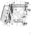
fig. 1 , is a perspective view of a cooking apparatus according to principles of the present invention; -
fig. 2 , is a different perspective view of the cooking apparatus offig.1 with a heat reflective vault installed; -
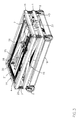
fig. 3 , is a perspective view of the cooking apparatus offig.1 partially disassembled, collapsed and packed for storage. - Referring to
fig. 1 and2 , the illustrated cooking apparatus has a four sided open lower frame 1 made of rectangular shape irons withswivel casters 2 and upwardly directedbumpers 3 at each corner. The lower ends of a parallel pair ofscissor arms 4 are pivotally attached to shaft 5 journaled in bosses 6, which are mounted in two adjacent corners of frame 1. A crossing pair ofscissor arms 7 is pivotally attached to shaft 8, which is journaled at either end in a pair of wheels 9 located inside the frame 1. Thescissor arms pivot 10. - The center of shaft 8 is journaled in
nut 11, which is threaded on lead screw 12, which is rotatably mounted on the underside ofbracket 13. The outside end of the lead screw 12 is attached tocrank wheel 14. The inside end of the lead screw 12 is attached through splined connector 15 (fig. 2 ) toelevator motor 16, which is supported onplatform 17 of frame 1. - A
fire bed 18 in the form of a metal tray designed to hold a charcoal fire rests inside and onupper frame 19. In one embodiment the tray is 122 cm long and 61 cm wide, although these dimensions may be different in other embodiments.Upper frame 19 constructed in a manner similar to lower frame 1, has downwardly directedbumpers 20, and a shaft 21 (fig. 3 ) supported on wheels (not shown) similar to wheels 9 on frame 1. - The upper ends of
scissor arms 4 are pivotally attached toshaft 21. The upper ends ofscissor arms 7 are pivotally attached to shaft 22 (fig. 3 ) which is mounted in a manner similar to previously mentioned shaft 5. - Accordingly,
scissor arms upper frame 19. Specifically,elevator motor 16 can turn lead screw 12 to movenut 11 and shaft 8 longitudinally. Consequently, the spacing between the lower ends ofarms arms height frame 19 changes asshaft 21 moves in the same direction as shaft 8 to accommodate the motion ofarms -
Limit switches 23 and 24 (fig. 2 ) mounted at each end of lead screw 12 can stopmotor 16 whennut 11 reaches one of the ends of the lead screw 12, to stopelevator motor 16 to prevent over traveling offire bed 18. - In one embodiment
upper frame 19 had a height that was adjustable from 25cm to 106 cm, although this range may be different in other embodiments. -
Frames screws 27.Bearing blocks atop frames Bearings rotisserie spit 30. Rotisseriespit 30 has a number ofconventional skewers - A
crank wheel 34 is attached to one end ofspit 30, the other end being attached through thesplined connector 35 to spitmotor 36 which is supported bybox 37, which is in turn supported byframe 25.Box 37 contains a motor control, such as a commercially available motor speed controller designed to adjust the speed ofmotor 36. The motor control has manual controls such knobs and switch handles for adjusting the speed and direction of motor 36 (and as will be described presently, the direction of motor 16). In one embodiment there are four controls: two for thescissor lift spit 30. In particular, the angular speed of thespit 30 may be regulated to a constant speed somewhere between 6 to 20 rpm, although other speed ranges are contemplated (e.g., between 10 to 12 rpm). The two controls for thescissor lift fire bed 18 and also control the speed of movement. The lift controllers operated in automated and/or manual mode. - Power is brought to
box 37 throughpower cord 38 andconnector 39 from junction box (not shown), which has asocket 40 for receiving a power supplying line (not shown). Thepower cord 38 is routed through the inside offrame 25 into the interior ofbox 37. -
Column 41 andcolumn 42 are attached atopframe 25, respectively 26.Columns reflective vault 43, for example a cylindrical metal reflector that may be made of sheet aluminum or stainless steel. The heatreflective vault 43 has a concave underside. - In addition to heat
reflective vault 43, there is a heat reflective blanket (not shown) made of fiberglass attached to heatreflective vault 43. The heat reflective blanket has the same purpose as heat reflective vault, namely to reflecting radiant heat back and increasing cooking efficiency. - A
temperature gauge 44 centrally mounted along one edge of the heatreflective vault 43 can display the temperature of thefire bed 18. - To facilitate an understanding of the principles associated with the foregoing apparatus, its operation will be briefly described. The cooking apparatus can be set up as shown in
fig. 1 and the swivel casters 2 (with brakes) ensure excellent manoeuvrability. To begin, a user can fillfire bed 18 with charcoal or other combustible fuel and ignite it. The user can also releaseclamshell bearings spit 30 out axially disconnecting it fromsplined connector 35. - In the usual fashion, spit 30 can be inserted through a piece of meat such as a whole adult pig or lamb. The
skewer 32 can be inserted radially through the pig carcass (and locked with thecrosspieces 45 and 46) whileskewers spit 30 can be reconnected tosplined connector 35 and placed inbearings reflective vault 43 with thecolumns frames - The user can check the cooking temperature by observing the reading on
temperature gauge 44. If the temperature is inappropriate, the height offire bed 18 can be adjusted by turningcrank wheel 14 to rotate lead screw 12 and movenut 11 axially. As previously mentioned, shaft 8 moves withnut 11 to change the separation between the lower ends ofscissor arms frame 19 andfire bed 18. - The user can continually turn
crank wheel 34 to rotate the spit and the meat supported thereon. In some cases crankwheel 34 may be turned in angular increments every five minutes or so. In most cases, however, the user will operatecontrols 47 oncontrol box 37 to startmotor 36 and rotatespit 30. These controls can be used to set the direction of rotation as well as setting the speed, somewhere in the range of perhaps 6-20 rpm. - The power for this process will be supplied by a power cord plugged into junction box, which will in turn transmit power through
cable 38 to controlbox 37. This power can be supplied by public utility or, for embodiments having appropriate power converters, from a storage battery, such as an automobile battery. - As the cooking proceeds the heat from
fire bed 18 can change. The user may operatecontrols 47 to begin automatically adjusting the height offire bed 18. - The cooking method according to the present invention comprising following steps of:
- setting of a piece of meat such as an adult pig, lamb or turkey on the
spit 30; - checking of temperature in the vicinity of said meat toward the predetermined standard;
- adjusting vertically the
fire bed 18 to bring the temperature in the vicinity of said meat toward the predetermined standard; - reflecting back the radiant heat toward the said meat installed on the
spit 30 without blocking the front and the side view; - collapsing the rotisserie grill when cooking is completed together with the fire bed and reflector before storage / packing.
- As the meat on
spit 30 cooks, heat fromfire bed 18 or from the meat itself can radiate upwardly, but it will be reflected back toward the cooking meat by the heatreflective vault 43. This greatly increases the efficiency of cooking. Also, heatreflective vault 43 does not fully enclose the meat onspit 30. Therefore, the use can watch the cooking process to judge its progress or simply for the pleasure of watching. Moreover, since the cooking meat is accessible from the side, the user is able to baste the meat or make sample cuts to judge how well the meat is cooking. - Eventually, the meat on
spit 30 will be done and the roasted meat can be served directly fromspit 30. In that case, the user will want to lowerfire bed 18 to a lower position and place grates 48 above thefire bed 18. The carved meat can be maintained warm ongrates 48 to be served eventually. The user will then stopmotors reflective vault 43 can now be removed. In some cases spit 30 will be released frombearings spit 30 can be removed by releasingskewers - When the foregoing cooking apparatus is no longer needed the ashes in
fire bed 18 can be discarded andfire bed 18 and spit 30 with itsskewers - Using either crank
wheel 14 ormotor 16,frame 19 will now be fully lowered, withbumpers 20 resting onbumpers 3 of frame 1.Frames screw 27, which can later be rethreaded in to frame 1. - The various dissembled components can be packed as shown in
fig. 3 . This compact packing allows the cooking apparatus to be stored or hoisted onto a transport (e.g., the trunk of an automobile). Thefire bed 18 can be first filled with various components such asskewers reflective vault 43 and heat blanket. The loadedfire bed 18 can then be slid under frame 1 between theswivel casters 2. - When fully closed, the
scissor lift motors 16 and 36 (electrical or hydraulic) are hidden and protected inside theframes 1, 19. They do not contribute to the overall height of the apparatus. The overall height is primarily determined by the thickness offrames 1, 19 and theswivel casters 2. The resulting package may be about 30 cm tall and be easily stored in a garage or various other storage locations. - This sturdy design and the use of non-corrosive materials and self-lubricating bearings, provide reliability, durability and low maintenance.
- It is appreciate that various modifications may be implemented with respect to the above described, preferred embodiment. Fore example, the temperature can be measured by a wireless thermometer inserted into the roasted meat. In some embodiments the rotisserie spit may be replaced with a conventional grill. The drive mechanism for adjusting the height of the fire box may employ hoisting cables or chains, hydraulic pistons, vertically screws, racks and pinions, etc. The size, shape, and thickness of the various components, as well as the materials used to build the components, can be selected to produce the desired strength, durability, temperature stability, styling, etc.
- Obviously, many modifications and variations of the present invention are possible in light of the above teachings. It is therefore to be understood that within the scope of the appended claims, the invention may be practice otherwise than as specifically described.
Claims (7)
- Portable rotisserie grill containing a rotisserie spit (30) and a fire bed (18), characterized in that comprising a:- a lower frame (1) with swivel casters (2) with brakes,- an upper frame (19) supporting the fire bed (18) in the form of a metallic tray,- a rotisserie spit (30) with food engaging structure that can accommodate a pig, lamb or turkey,- two frames (25 and 26) attached to lower frame (1) by thumb-screws (27),- two bearing blocks (28 and 29) mounted atop frames (25 and 26) that hold rotisserie spit (30);- two columns (41 and 42) mounted atop bearing (28 and 29);- heat reflective vault (43), mounted on columns (41 and 42), that reflects the heat back down toward spit (30);- a temperature gauge (44) mounted centrally along one edge of the heat reflective vault (43) that monitors the temperature of fire bed (18);- a control box (37) that controls two motors (16 and 36);- a scissor arms drive mechanism for vertically adjusting the position of fire bed (18) either manually, using a crank wheel (14) or automatically using the elevator motor (16).
- Portable rotisserie grill according to claim 1 wherein said food support comprises:- a rotisserie spit (30) mounted on bearings (28, 29) that has a splined connector (35) for locking or quickly disconnecting said rotisserie spit (30) from spit motor (36);- a skewer (32) that can be inserted radially through the pig carcass and locked with the crosspieces (45 and 46) while other skewers (31 and 33) can be inserted into either end of the meat;- a crank wheel (34) attached to one end of spit (30) whereas the opposite end of spit (30) is connecting through splined connector (35) to a spit motor (36) that rotates the meat;- a speed controller that regulates the angular speed of spit motor (36);- grates (48) that are placed over fire bed (18) to maintain the carved meat warm and ready to be served eventually.
- Portable rotisserie grill according to claim 1 comprising a heat reflective vault (43), mounted over rotisserie spit (30) reflecting radiant heat back down toward said rotisserie spit without laterally enclosing said rotisserie spit.
- Portable rotisserie grill according to claim 1 comprising:- a scissor lift connected between upper and lower frames, said scissor lift having a pair of upper ends coupled to said upper frame and a pair of lower ends coupled to lower frame;- a lead screw (12) coupled to elevator motor (16) and having a nut (11) that adjusts automatically the space between said scissor lift pairs of arms (4, 7);- a crank handle (11) attached to opposite end of said lead screw (12) that adjusts manually the space between said scissor lift pairs of arms (4, 7);- a pair of limit switches (23, 24) responsive to motion of said scissor lift mechanism and coupled to said elevator motor (16) for stopping it in order to prevent excessive travel of said fire bed (18).
- Portable rotisserie grill according to claims 1 and 4 comprising a temperature gauge (44) responsive to heat from said fire bed (18) and coupled to said elevator motor for controlling elevation of said fire bed, said temperature gauge (44) being powered from external power source through socket (40), power connector (39), power cord (38), control box (37).
- Portable rotisserie grill according to claim 1 wherein rotisserie spit (30), conventional skewers (31, 32 and 33), heat reflective vault (43), frames (25, 26) are stored inside metallic tray of fire bed (18), said metallic tray being stored under the collapsed frame of the cooking apparatus between the swivel casters (2).
- Cooking method according to portable rotisserie grill to claims 1 through 6, characterized in that, comprising following steps of:- placing a whole pig, lamb or turkey on rotisserie spit (30);- comparing the temperature in the vicinity of said meat to predetermined standard;- regularly adjusting the fire bed (18) vertically to bring the temperature in the vicinity of said meat toward the predetermined standard;- reflecting back the radiant heat without laterally enclosing said rotisserie spit (30), and- rollapsing the rotisserie spit (30), the fire bed (18), the heat reflective vault (43) together when cooking is done and before storing them.
Applications Claiming Priority (1)
| Application Number | Priority Date | Filing Date | Title |
|---|---|---|---|
| ROA200700341A RO123313B1 (en) | 2007-05-23 | 2007-05-23 | Portable roaster |
Publications (1)
| Publication Number | Publication Date |
|---|---|
| EP1994865A1 true EP1994865A1 (en) | 2008-11-26 |
Family
ID=39684404
Family Applications (1)
| Application Number | Title | Priority Date | Filing Date |
|---|---|---|---|
| EP08464009A Withdrawn EP1994865A1 (en) | 2007-05-23 | 2008-05-23 | Portable rotisserie grill and cooking method |
Country Status (2)
| Country | Link |
|---|---|
| EP (1) | EP1994865A1 (en) |
| RO (1) | RO123313B1 (en) |
Cited By (15)
| Publication number | Priority date | Publication date | Assignee | Title |
|---|---|---|---|---|
| ITMI20090496A1 (en) * | 2009-03-30 | 2010-09-30 | Gestione Immobili Paolino Di Pennac Chioli Paolino | CARBON DEVICE FOR COOKING OUTDOORS |
| ITTO20100713A1 (en) * | 2010-08-26 | 2012-02-27 | Carlo Porello | APPARATUS OF COOKING FOOD WITH BRACE |
| CN102835909A (en) * | 2012-08-29 | 2012-12-26 | 余凤康 | Multifunctional oven |
| CN103542431A (en) * | 2012-07-09 | 2014-01-29 | 段保国 | Liftable coal replacing device |
| US20140261377A1 (en) * | 2013-03-15 | 2014-09-18 | Kiosky Chung | Barbecue apparatus |
| CN106235902A (en) * | 2016-08-31 | 2016-12-21 | 石张宇 | Outdoor travel Multifunction stove with oven |
| CN108523697A (en) * | 2018-07-06 | 2018-09-14 | 朱淑君 | Oven |
| CN108552975A (en) * | 2018-04-13 | 2018-09-21 | 梅金琪 | A kind of novel travelling equipment |
| CN109730463A (en) * | 2019-01-23 | 2019-05-10 | 宁波欧琳整体厨房有限公司 | A lifting device and lifting cabinet |
| US20190368745A1 (en) * | 2018-06-04 | 2019-12-05 | Harmonious International Ltd. | Oven rotisserie |
| US10527221B2 (en) | 2016-12-20 | 2020-01-07 | James Daniel Grappe | Apparatus for storing and transporting items |
| US10736461B2 (en) | 2017-03-31 | 2020-08-11 | Chris Stephen Manos | Storable grill |
| WO2022110729A1 (en) * | 2020-11-26 | 2022-06-02 | 傲基科技股份有限公司 | Fast-folding brazier |
| CN115024642A (en) * | 2022-06-23 | 2022-09-09 | 广东海新智能厨房股份有限公司 | A heavy duty oven that is easy to move and height adjustable |
| US20240225354A1 (en) * | 2023-01-06 | 2024-07-11 | Larry Vansickel | Reconfigurable barbeque cooker |
Citations (8)
| Publication number | Priority date | Publication date | Assignee | Title |
|---|---|---|---|---|
| CH386072A (en) * | 1961-03-17 | 1964-12-31 | P & W Blattmann Metallwaren Un | Portable grill |
| US3943837A (en) * | 1975-05-08 | 1976-03-16 | Theodore Trkla | Dual purpose barbecue grill and rotisserie |
| DE3227346A1 (en) * | 1982-07-22 | 1984-01-26 | Otto 4057 Brüggen Lehmann | Infinitely variable fuel/grate spacing controller |
| DE29720850U1 (en) * | 1996-11-29 | 1998-03-19 | Hohmann Herstellungs- und Vertriebs-GmbH, 96317 Kronach | Garden grill with vertically adjustable grill base by means of an eccentric lever function |
| FR2759888A1 (en) * | 1997-02-25 | 1998-08-28 | Falange Comercio Internacional | Barbecue with adjustable height grid above hearth |
| US5996572A (en) | 1999-05-18 | 1999-12-07 | Ilagan; Artemio M. | Turbo-charcoal barbecue |
| WO2000006415A1 (en) * | 1998-07-28 | 2000-02-10 | Lucien Baillon | Multipurpose wheeled cooking apparatus |
| DE20113620U1 (en) * | 2001-08-22 | 2002-01-17 | Drumm GmbH, 97337 Dettelbach | charcoal grill |
-
2007
- 2007-05-23 RO ROA200700341A patent/RO123313B1/en unknown
-
2008
- 2008-05-23 EP EP08464009A patent/EP1994865A1/en not_active Withdrawn
Patent Citations (8)
| Publication number | Priority date | Publication date | Assignee | Title |
|---|---|---|---|---|
| CH386072A (en) * | 1961-03-17 | 1964-12-31 | P & W Blattmann Metallwaren Un | Portable grill |
| US3943837A (en) * | 1975-05-08 | 1976-03-16 | Theodore Trkla | Dual purpose barbecue grill and rotisserie |
| DE3227346A1 (en) * | 1982-07-22 | 1984-01-26 | Otto 4057 Brüggen Lehmann | Infinitely variable fuel/grate spacing controller |
| DE29720850U1 (en) * | 1996-11-29 | 1998-03-19 | Hohmann Herstellungs- und Vertriebs-GmbH, 96317 Kronach | Garden grill with vertically adjustable grill base by means of an eccentric lever function |
| FR2759888A1 (en) * | 1997-02-25 | 1998-08-28 | Falange Comercio Internacional | Barbecue with adjustable height grid above hearth |
| WO2000006415A1 (en) * | 1998-07-28 | 2000-02-10 | Lucien Baillon | Multipurpose wheeled cooking apparatus |
| US5996572A (en) | 1999-05-18 | 1999-12-07 | Ilagan; Artemio M. | Turbo-charcoal barbecue |
| DE20113620U1 (en) * | 2001-08-22 | 2002-01-17 | Drumm GmbH, 97337 Dettelbach | charcoal grill |
Cited By (19)
| Publication number | Priority date | Publication date | Assignee | Title |
|---|---|---|---|---|
| ITMI20090496A1 (en) * | 2009-03-30 | 2010-09-30 | Gestione Immobili Paolino Di Pennac Chioli Paolino | CARBON DEVICE FOR COOKING OUTDOORS |
| ITTO20100713A1 (en) * | 2010-08-26 | 2012-02-27 | Carlo Porello | APPARATUS OF COOKING FOOD WITH BRACE |
| WO2012025807A1 (en) * | 2010-08-26 | 2012-03-01 | Carlo Porello | Equipment for cooking barbecue food |
| CN103542431A (en) * | 2012-07-09 | 2014-01-29 | 段保国 | Liftable coal replacing device |
| CN103542431B (en) * | 2012-07-09 | 2017-06-13 | 山东明晟化工工程有限公司 | A kind of liftable briquet changing device |
| CN102835909A (en) * | 2012-08-29 | 2012-12-26 | 余凤康 | Multifunctional oven |
| US20140261377A1 (en) * | 2013-03-15 | 2014-09-18 | Kiosky Chung | Barbecue apparatus |
| CN106235902A (en) * | 2016-08-31 | 2016-12-21 | 石张宇 | Outdoor travel Multifunction stove with oven |
| US10527221B2 (en) | 2016-12-20 | 2020-01-07 | James Daniel Grappe | Apparatus for storing and transporting items |
| US10736461B2 (en) | 2017-03-31 | 2020-08-11 | Chris Stephen Manos | Storable grill |
| US11812893B2 (en) | 2017-03-31 | 2023-11-14 | Chris Stephen Manos | Storable grill |
| CN108552975A (en) * | 2018-04-13 | 2018-09-21 | 梅金琪 | A kind of novel travelling equipment |
| US20190368745A1 (en) * | 2018-06-04 | 2019-12-05 | Harmonious International Ltd. | Oven rotisserie |
| US12442538B2 (en) * | 2018-06-04 | 2025-10-14 | Harmonious International Ltd. | Oven rotisserie |
| CN108523697A (en) * | 2018-07-06 | 2018-09-14 | 朱淑君 | Oven |
| CN109730463A (en) * | 2019-01-23 | 2019-05-10 | 宁波欧琳整体厨房有限公司 | A lifting device and lifting cabinet |
| WO2022110729A1 (en) * | 2020-11-26 | 2022-06-02 | 傲基科技股份有限公司 | Fast-folding brazier |
| CN115024642A (en) * | 2022-06-23 | 2022-09-09 | 广东海新智能厨房股份有限公司 | A heavy duty oven that is easy to move and height adjustable |
| US20240225354A1 (en) * | 2023-01-06 | 2024-07-11 | Larry Vansickel | Reconfigurable barbeque cooker |
Also Published As
| Publication number | Publication date |
|---|---|
| RO123313B1 (en) | 2011-07-29 |
Similar Documents
| Publication | Publication Date | Title |
|---|---|---|
| EP1994865A1 (en) | Portable rotisserie grill and cooking method | |
| US7856924B1 (en) | Collapsible barbeque with variable firebed position and method of use | |
| US3943837A (en) | Dual purpose barbecue grill and rotisserie | |
| CA2868084C (en) | Adjustable fire pit grill | |
| US3103161A (en) | Barbecuing apparatus | |
| US9993109B2 (en) | Rotisserie rod and adaptor | |
| US20030029436A1 (en) | Barbecue grill and cart assembly | |
| US11602242B2 (en) | Portable grill device | |
| US11478109B2 (en) | Barbecue with spit functionality | |
| US4815367A (en) | Flashlight powered cooking rotisserie | |
| US5908026A (en) | Portable vertical rotary grill | |
| US20190053661A1 (en) | Barbeque construction kit | |
| US2486345A (en) | Barbecue spit | |
| US20020074961A1 (en) | Barbeque cover support device | |
| US5237912A (en) | Heating and cooking apparatus | |
| CN210784025U (en) | Grill with rotary meat roaster function | |
| US20090000609A1 (en) | Cooking grill with electrically driven variable height fire box | |
| CN119156158A (en) | Outdoor cooking device | |
| KR101744439B1 (en) | Skewered food roasted device for fire power level adjusting | |
| KR200494945Y1 (en) | Skewer roast device | |
| WO2006083705A2 (en) | Portable cooking equipment | |
| CN209450355U (en) | A kind of oven | |
| CN213940525U (en) | Oven frame is used to open air convenient to installation | |
| KR20140003166U (en) | Portable barbecue rotation unit | |
| KR101519722B1 (en) | Portable charcoal fire roasting device |
Legal Events
| Date | Code | Title | Description |
|---|---|---|---|
| PUAI | Public reference made under article 153(3) epc to a published international application that has entered the european phase |
Free format text: ORIGINAL CODE: 0009012 |
|
| AK | Designated contracting states |
Kind code of ref document: A1 Designated state(s): AT BE BG CH CY CZ DE DK EE ES FI FR GB GR HR HU IE IS IT LI LT LU LV MC MT NL NO PL PT RO SE SI SK TR |
|
| AX | Request for extension of the european patent |
Extension state: AL BA MK RS |
|
| AKX | Designation fees paid |
Designated state(s): AT BE BG CH CY CZ DE DK EE ES FI FR GB GR HR HU IE IS IT LI LT LU LV MC MT NL NO PL PT RO SE SI SK TR |
|
| STAA | Information on the status of an ep patent application or granted ep patent |
Free format text: STATUS: THE APPLICATION IS DEEMED TO BE WITHDRAWN |
|
| 18D | Application deemed to be withdrawn |
Effective date: 20090527 |