EP1994595B1 - Fuel cell coolant bubble control - Google Patents
Fuel cell coolant bubble control Download PDFInfo
- Publication number
- EP1994595B1 EP1994595B1 EP06849079A EP06849079A EP1994595B1 EP 1994595 B1 EP1994595 B1 EP 1994595B1 EP 06849079 A EP06849079 A EP 06849079A EP 06849079 A EP06849079 A EP 06849079A EP 1994595 B1 EP1994595 B1 EP 1994595B1
- Authority
- EP
- European Patent Office
- Prior art keywords
- coolant
- passageways
- fuel cell
- gas
- channels
- Prior art date
- Legal status (The legal status is an assumption and is not a legal conclusion. Google has not performed a legal analysis and makes no representation as to the accuracy of the status listed.)
- Active
Links
- 239000002826 coolant Substances 0.000 title claims description 234
- 239000000446 fuel Substances 0.000 title claims description 196
- 239000000376 reactant Substances 0.000 claims description 108
- 239000007800 oxidant agent Substances 0.000 claims description 41
- 230000001590 oxidative effect Effects 0.000 claims description 41
- 239000007788 liquid Substances 0.000 claims description 40
- 238000000034 method Methods 0.000 claims description 11
- 239000000463 material Substances 0.000 claims description 8
- 230000000903 blocking effect Effects 0.000 claims description 7
- 239000003792 electrolyte Substances 0.000 claims description 6
- 206010063659 Aversion Diseases 0.000 claims description 4
- 230000000116 mitigating effect Effects 0.000 claims description 4
- 230000000712 assembly Effects 0.000 claims description 3
- 238000000429 assembly Methods 0.000 claims description 3
- 239000003054 catalyst Substances 0.000 claims description 3
- 239000002131 composite material Substances 0.000 claims description 2
- 239000007789 gas Substances 0.000 description 219
- XLYOFNOQVPJJNP-UHFFFAOYSA-N water Substances O XLYOFNOQVPJJNP-UHFFFAOYSA-N 0.000 description 74
- 230000002209 hydrophobic effect Effects 0.000 description 18
- 238000001816 cooling Methods 0.000 description 11
- 230000001154 acute effect Effects 0.000 description 9
- 239000012528 membrane Substances 0.000 description 6
- 230000036571 hydration Effects 0.000 description 5
- 238000006703 hydration reaction Methods 0.000 description 5
- LYCAIKOWRPUZTN-UHFFFAOYSA-N Ethylene glycol Chemical compound OCCO LYCAIKOWRPUZTN-UHFFFAOYSA-N 0.000 description 4
- 229920000049 Carbon (fiber) Polymers 0.000 description 3
- 239000004917 carbon fiber Substances 0.000 description 3
- 238000009792 diffusion process Methods 0.000 description 3
- VNWKTOKETHGBQD-UHFFFAOYSA-N methane Chemical compound C VNWKTOKETHGBQD-UHFFFAOYSA-N 0.000 description 3
- 238000009428 plumbing Methods 0.000 description 3
- 238000010408 sweeping Methods 0.000 description 3
- ATJFFYVFTNAWJD-UHFFFAOYSA-N Tin Chemical compound [Sn] ATJFFYVFTNAWJD-UHFFFAOYSA-N 0.000 description 2
- 230000000694 effects Effects 0.000 description 2
- 238000007710 freezing Methods 0.000 description 2
- 230000008014 freezing Effects 0.000 description 2
- 230000005484 gravity Effects 0.000 description 2
- WGCNASOHLSPBMP-UHFFFAOYSA-N hydroxyacetaldehyde Natural products OCC=O WGCNASOHLSPBMP-UHFFFAOYSA-N 0.000 description 2
- 230000014759 maintenance of location Effects 0.000 description 2
- 238000013508 migration Methods 0.000 description 2
- 230000005012 migration Effects 0.000 description 2
- 230000035699 permeability Effects 0.000 description 2
- 238000013022 venting Methods 0.000 description 2
- WYTGDNHDOZPMIW-RCBQFDQVSA-N alstonine Natural products C1=CC2=C3C=CC=CC3=NC2=C2N1C[C@H]1[C@H](C)OC=C(C(=O)OC)[C@H]1C2 WYTGDNHDOZPMIW-RCBQFDQVSA-N 0.000 description 1
- 238000013459 approach Methods 0.000 description 1
- 230000015572 biosynthetic process Effects 0.000 description 1
- 230000015556 catabolic process Effects 0.000 description 1
- 239000011248 coating agent Substances 0.000 description 1
- 238000000576 coating method Methods 0.000 description 1
- 238000006731 degradation reaction Methods 0.000 description 1
- 230000018044 dehydration Effects 0.000 description 1
- 238000006297 dehydration reaction Methods 0.000 description 1
- 230000002328 demineralizing effect Effects 0.000 description 1
- 238000010586 diagram Methods 0.000 description 1
- 230000005611 electricity Effects 0.000 description 1
- 239000000835 fiber Substances 0.000 description 1
- 230000037406 food intake Effects 0.000 description 1
- 239000002737 fuel gas Substances 0.000 description 1
- 238000010438 heat treatment Methods 0.000 description 1
- 238000004519 manufacturing process Methods 0.000 description 1
- 230000013011 mating Effects 0.000 description 1
- 239000000203 mixture Substances 0.000 description 1
- 239000011148 porous material Substances 0.000 description 1
- 238000012545 processing Methods 0.000 description 1
- 230000001105 regulatory effect Effects 0.000 description 1
- 230000000717 retained effect Effects 0.000 description 1
- 239000007787 solid Substances 0.000 description 1
- 230000003068 static effect Effects 0.000 description 1
- 238000012546 transfer Methods 0.000 description 1
Images


Classifications
-
- H—ELECTRICITY
- H01—ELECTRIC ELEMENTS
- H01M—PROCESSES OR MEANS, e.g. BATTERIES, FOR THE DIRECT CONVERSION OF CHEMICAL ENERGY INTO ELECTRICAL ENERGY
- H01M8/00—Fuel cells; Manufacture thereof
- H01M8/24—Grouping of fuel cells, e.g. stacking of fuel cells
-
- H—ELECTRICITY
- H01—ELECTRIC ELEMENTS
- H01M—PROCESSES OR MEANS, e.g. BATTERIES, FOR THE DIRECT CONVERSION OF CHEMICAL ENERGY INTO ELECTRICAL ENERGY
- H01M8/00—Fuel cells; Manufacture thereof
- H01M8/04—Auxiliary arrangements, e.g. for control of pressure or for circulation of fluids
- H01M8/04007—Auxiliary arrangements, e.g. for control of pressure or for circulation of fluids related to heat exchange
- H01M8/04029—Heat exchange using liquids
-
- H—ELECTRICITY
- H01—ELECTRIC ELEMENTS
- H01M—PROCESSES OR MEANS, e.g. BATTERIES, FOR THE DIRECT CONVERSION OF CHEMICAL ENERGY INTO ELECTRICAL ENERGY
- H01M8/00—Fuel cells; Manufacture thereof
- H01M8/02—Details
- H01M8/0202—Collectors; Separators, e.g. bipolar separators; Interconnectors
- H01M8/0204—Non-porous and characterised by the material
- H01M8/0223—Composites
- H01M8/0228—Composites in the form of layered or coated products
-
- H—ELECTRICITY
- H01—ELECTRIC ELEMENTS
- H01M—PROCESSES OR MEANS, e.g. BATTERIES, FOR THE DIRECT CONVERSION OF CHEMICAL ENERGY INTO ELECTRICAL ENERGY
- H01M8/00—Fuel cells; Manufacture thereof
- H01M8/02—Details
- H01M8/0202—Collectors; Separators, e.g. bipolar separators; Interconnectors
- H01M8/023—Porous and characterised by the material
- H01M8/0241—Composites
- H01M8/0245—Composites in the form of layered or coated products
-
- H—ELECTRICITY
- H01—ELECTRIC ELEMENTS
- H01M—PROCESSES OR MEANS, e.g. BATTERIES, FOR THE DIRECT CONVERSION OF CHEMICAL ENERGY INTO ELECTRICAL ENERGY
- H01M8/00—Fuel cells; Manufacture thereof
- H01M8/02—Details
- H01M8/0202—Collectors; Separators, e.g. bipolar separators; Interconnectors
- H01M8/0258—Collectors; Separators, e.g. bipolar separators; Interconnectors characterised by the configuration of channels, e.g. by the flow field of the reactant or coolant
- H01M8/026—Collectors; Separators, e.g. bipolar separators; Interconnectors characterised by the configuration of channels, e.g. by the flow field of the reactant or coolant characterised by grooves, e.g. their pitch or depth
-
- H—ELECTRICITY
- H01—ELECTRIC ELEMENTS
- H01M—PROCESSES OR MEANS, e.g. BATTERIES, FOR THE DIRECT CONVERSION OF CHEMICAL ENERGY INTO ELECTRICAL ENERGY
- H01M8/00—Fuel cells; Manufacture thereof
- H01M8/02—Details
- H01M8/0202—Collectors; Separators, e.g. bipolar separators; Interconnectors
- H01M8/0258—Collectors; Separators, e.g. bipolar separators; Interconnectors characterised by the configuration of channels, e.g. by the flow field of the reactant or coolant
- H01M8/0265—Collectors; Separators, e.g. bipolar separators; Interconnectors characterised by the configuration of channels, e.g. by the flow field of the reactant or coolant the reactant or coolant channels having varying cross sections
-
- H—ELECTRICITY
- H01—ELECTRIC ELEMENTS
- H01M—PROCESSES OR MEANS, e.g. BATTERIES, FOR THE DIRECT CONVERSION OF CHEMICAL ENERGY INTO ELECTRICAL ENERGY
- H01M8/00—Fuel cells; Manufacture thereof
- H01M8/02—Details
- H01M8/0202—Collectors; Separators, e.g. bipolar separators; Interconnectors
- H01M8/0267—Collectors; Separators, e.g. bipolar separators; Interconnectors having heating or cooling means, e.g. heaters or coolant flow channels
-
- H—ELECTRICITY
- H01—ELECTRIC ELEMENTS
- H01M—PROCESSES OR MEANS, e.g. BATTERIES, FOR THE DIRECT CONVERSION OF CHEMICAL ENERGY INTO ELECTRICAL ENERGY
- H01M8/00—Fuel cells; Manufacture thereof
- H01M8/04—Auxiliary arrangements, e.g. for control of pressure or for circulation of fluids
-
- H—ELECTRICITY
- H01—ELECTRIC ELEMENTS
- H01M—PROCESSES OR MEANS, e.g. BATTERIES, FOR THE DIRECT CONVERSION OF CHEMICAL ENERGY INTO ELECTRICAL ENERGY
- H01M8/00—Fuel cells; Manufacture thereof
- H01M8/04—Auxiliary arrangements, e.g. for control of pressure or for circulation of fluids
- H01M8/04007—Auxiliary arrangements, e.g. for control of pressure or for circulation of fluids related to heat exchange
- H01M8/04059—Evaporative processes for the cooling of a fuel cell
-
- H—ELECTRICITY
- H01—ELECTRIC ELEMENTS
- H01M—PROCESSES OR MEANS, e.g. BATTERIES, FOR THE DIRECT CONVERSION OF CHEMICAL ENERGY INTO ELECTRICAL ENERGY
- H01M8/00—Fuel cells; Manufacture thereof
- H01M8/04—Auxiliary arrangements, e.g. for control of pressure or for circulation of fluids
- H01M8/04082—Arrangements for control of reactant parameters, e.g. pressure or concentration
- H01M8/04089—Arrangements for control of reactant parameters, e.g. pressure or concentration of gaseous reactants
- H01M8/04119—Arrangements for control of reactant parameters, e.g. pressure or concentration of gaseous reactants with simultaneous supply or evacuation of electrolyte; Humidifying or dehumidifying
- H01M8/04126—Humidifying
- H01M8/04134—Humidifying by coolants
-
- H—ELECTRICITY
- H01—ELECTRIC ELEMENTS
- H01M—PROCESSES OR MEANS, e.g. BATTERIES, FOR THE DIRECT CONVERSION OF CHEMICAL ENERGY INTO ELECTRICAL ENERGY
- H01M8/00—Fuel cells; Manufacture thereof
- H01M8/24—Grouping of fuel cells, e.g. stacking of fuel cells
- H01M8/241—Grouping of fuel cells, e.g. stacking of fuel cells with solid or matrix-supported electrolytes
-
- H—ELECTRICITY
- H01—ELECTRIC ELEMENTS
- H01M—PROCESSES OR MEANS, e.g. BATTERIES, FOR THE DIRECT CONVERSION OF CHEMICAL ENERGY INTO ELECTRICAL ENERGY
- H01M8/00—Fuel cells; Manufacture thereof
- H01M8/24—Grouping of fuel cells, e.g. stacking of fuel cells
- H01M8/2457—Grouping of fuel cells, e.g. stacking of fuel cells with both reactants being gaseous or vaporised
-
- H—ELECTRICITY
- H01—ELECTRIC ELEMENTS
- H01M—PROCESSES OR MEANS, e.g. BATTERIES, FOR THE DIRECT CONVERSION OF CHEMICAL ENERGY INTO ELECTRICAL ENERGY
- H01M8/00—Fuel cells; Manufacture thereof
- H01M8/24—Grouping of fuel cells, e.g. stacking of fuel cells
- H01M8/2465—Details of groupings of fuel cells
- H01M8/2483—Details of groupings of fuel cells characterised by internal manifolds
-
- H—ELECTRICITY
- H01—ELECTRIC ELEMENTS
- H01M—PROCESSES OR MEANS, e.g. BATTERIES, FOR THE DIRECT CONVERSION OF CHEMICAL ENERGY INTO ELECTRICAL ENERGY
- H01M8/00—Fuel cells; Manufacture thereof
- H01M8/10—Fuel cells with solid electrolytes
- H01M2008/1095—Fuel cells with polymeric electrolytes
-
- Y—GENERAL TAGGING OF NEW TECHNOLOGICAL DEVELOPMENTS; GENERAL TAGGING OF CROSS-SECTIONAL TECHNOLOGIES SPANNING OVER SEVERAL SECTIONS OF THE IPC; TECHNICAL SUBJECTS COVERED BY FORMER USPC CROSS-REFERENCE ART COLLECTIONS [XRACs] AND DIGESTS
- Y02—TECHNOLOGIES OR APPLICATIONS FOR MITIGATION OR ADAPTATION AGAINST CLIMATE CHANGE
- Y02E—REDUCTION OF GREENHOUSE GAS [GHG] EMISSIONS, RELATED TO ENERGY GENERATION, TRANSMISSION OR DISTRIBUTION
- Y02E60/00—Enabling technologies; Technologies with a potential or indirect contribution to GHG emissions mitigation
- Y02E60/30—Hydrogen technology
- Y02E60/50—Fuel cells
Definitions
- Coolant passageway configuration reduces gas bubble blockage in small, low flow coolant passageways of fuel cells.
- the total volume of coolant in the fuel cells may be reduced.
- PEM proton exchange membrane
- Systems employing between-cell coolant plates, which have glycol or other coolants, may have extremely small, in-cell water passageways to provide low flows of water to the anode side of the fuel cells for hydration, with insignificant cooling resulting from the water flow.
- Coolant flow is assured in small fuel cell coolant passageways, mitigating bubble blockage of coolant flowing at a low flow rate in fuel cell coolant passageways; gas bubbles are assisted in flowing through coolant passageways of PEM fuel cells; venting of gas in PEM fuel cell coolant passageways is improved; flow of gas toward a vent is improved in PEM fuel cells; PEM fuel cell hydration is improved; and cooling is improved in PEM fuel cells.
- coolant flow passageways become smaller, they become more prone to being blocked by bubbles of any gas therein.
- a threshold coolant flow rate at or below which bubbles will block the coolant passageways if gas is present in the coolant; at coolant flow rates above the threshold, bubbles will be swept along by the flow of coolant, and will not block the coolant passageway.
- fuel cell may mean the apparatus for a complete, operative fuel cell capable of producing electricity from oxidant and fuel reactant gases, or where the context so requires, that term may mean the portion of a fuel cell exclusive of layers that provide coolant to the fuel cells, which may be disposed between adjacent ones of said fuel cell portions.
- liquid coolant means a coolant which is in the liquid state when the fuel cell is operating, even though such liquid coolant may freeze and become a solid when the fuel cell is not operating and the ambient temperature is below the freezing point of the coolant.
- the coolant may be water or other liquid; herein, “liquiphobic” is defined as having an aversion to the coolant, or lacking an affinity for the coolant, and “liquiphilic” is defined as having an affinity for, or lacking an aversion to, the coolant.
- the coolant flow assisted herein may, in some cases, be used primarily for hydration, with minimal cooling effect. Coolant flow paths and passageways herein are distinct from fuel and oxidant reactant gas flow field channels.
- coolant passageways refers to those portions of the coolant flow path in a fuel cell stack which are substantially coextensive with the planform (the in-plane outline) of the fuel cells.
- gas tolerant coolant passageways of fuel cells promote flow of coolant within such passageways with or without the presence of gas.
- the gas tolerant configurations are provided along substantially the entire length of coolant passageways, thereby to provide a contiguous gas flow capability from inlets of said passageways to outlets thereof.
- gas tolerant fuel cell coolant passageways are configured to provide portions for which gas has an affinity, that is, a propensity to migrate to such portions and to flow therein, in contrast with other portions of the passageways where coolant may flow without interference from gas, thereby to assure that there is room for coolant to flow without being blocked by gas bubbles.
- coolant passageways having gas tolerant cross sections may comprise first portions conducive to presence of gas preferentially in comparison with second portions which are less conducive to the presence of gas than the first portions.
- Gas tolerant passageways herein may comprise first and second portions within the same passageways: the first portions may be adjacent to a wall of a passageway which is liquiphobic; the first portions may each comprise a corner which subtends more than 90° between two walls of a passageway; the first portions may comprise a portion of a triangle, a trapezoid or other polygon away from acute angular areas thereof; or they may comprise combinations of the foregoing.
- the gas bubbles in the coolant channel are caused to be metastable by water channels which are diverging, that is which have a cross section of incrementally increasing size at corresponding incrementally increasing distances from the inlet of each channel.
- the bubble seeks to minimize its surface energy by seeking out a position in the channel where it will more closely approach having a spherical form. Diverging channels cause the metastable bubbles to move in the direction toward the exit of the channel, which is the direction of water flow, ensuring that blockage of water flow as a result of gas in the channel will be minimized.
- the flow of coolant is the purpose, rather than the flow of gas; however, the control of gas flow is accomplished by affecting the characteristics of the coolant channels with respect to gas: that is, while the coolant flow characteristics at low flow rates are essentially the same in one portion of the gas tolerant coolant passageways as in other portions thereof, provides certain portions of gas tolerant channels are provided for which gas has an affinity. Therefore, affecting the flow of gas within the passageway accomplishes the flow of coolant within the passageway, whether or not gas is present.
- a fuel cell system employing evaporative cooling is disclosed in U.S. Serial No. 11/230,066 filed September 19, 2005 , now publication No. US2006-0141331 and described with respect to Figs. 1 and 2 herein.
- water evaporates into air, pumped 52 through an air inlet 53, within the oxidant reactant gas (air) flow fields in the stack 37 thereby cooling the fuel cells 38 ( Fig. 2 ).
- the outflow 57 of the oxidant reactant gas channels passes through a condenser 59 wherein heat is removed and the water is recovered and returned over a conduit 60 to a water/gas separator 64 which also serves as a reservoir. Any gas separated from the water is removed through exhaust 62, the water returning via a conduit 65 and a coolant inlet 66 to the water passageways in the stack 37 and upward toward an outlet 68.
- fuel cells 38 each comprise a conventional membrane electrode assembly 72, which includes an electrolyte with anode and cathode catalysts on opposite sides thereof and may include a gas diffusion layer on one or both electrodes.
- Fuel reactant gas flows through channels 74 in a fuel reactant gas flow field plate 75 having grooves 76, which together with grooves 77 of an adjacent fuel cell, form minute water passageways 78 at a juncture 79 of the fuel cells 38.
- an oxidant reactant gas flow field plate 81 includes air flow channels 82 and grooves 83 which, with grooves 84 on an adjacent fuel cell, together form minute water passageways 85 at a juncture 86 of the fuel cells.
- pressure of water in the passageways is between one and ten Kilopascals lower than the pressure of the reactant gases, such as provided by an air pump and pressure-regulated fuel.
- the passageways may be formed other than by matching grooves as shown, such as by channels 76, 83 or 77, 84 provided in only one of the reactant gas flow field plates 75, 81.
- the reactant gas flow field plates 75, 81 appear to be the same as water transport plates, sometimes referred to as fine pore plates, in a fuel cell power plant which utilizes significant water flow through the water transport plates, with external water processing, as is disclosed in U.S. patent 5,700,595 .
- the water flow channels of the aforesaid '595 patent have cross sections which are several tens of times larger than the cross sections of the water passageways 78, 85 in Fig. 2 .
- a material which is conductive, hydrophilic and has a high permeability to water extending over substantially the entire planform of the reactant gas flow field plates 75, 81 in place of grooves forming passageways 78, 85.
- Such material may be carbon fiber paper, with fibers aligned in the direction of water motion to help with in-plane water permeability, or it may be other material conventionally used as fuel cell diffusion media.
- the water passageways are typically very small and capable of providing the water required for evaporative cooling.
- Water flow in addition to that needed for evaporative cooling can assist in removing gas bubbles which leak in from the reactant gas channels, and may assist in deionizing (demineralizing) water which is circulating in the system.
- deionizing (demineralizing) water which is circulating in the system.
- Such water flow can be adequate if provided by a pump and plumbing external to the fuel cells.
- gas tolerant coolant passageways such as the passageways 78, 85 in Figs. 3 and 4 .
- the general planforms of fuel cells are normal to Figs. 2-22 , and are illustrated (in specific forms) in Figs. 23 and 24 .
- Gas tolerant coolant passageways 78, 85 comprise rectangular channels 76, 84 extending inwardly from a surface 91 of the fuel reactant gas flow field plates 75, opposite to a surface 90 from which the fuel flow field channels 74 extend, and channels 77, 83 having rectangular cross sections, significantly smaller than the cross sections of the channels 76, 84.
- the channels 77, 83 extend from a surface 93 of the oxidant reactant gas flow field plate 81 which is opposite to a surface 92 from which the oxidant reactant gas channels 82 extend.
- any gas within the passageways 78, 85 migrate and/or be retained in the larger rectangles 76, 84, rather than in the smaller rectangles 77, 83.
- the first portion of the coolant passageways formed by the large rectangles 77, 83 is conducive to the presence of gas preferentially over the second portion of the passageways which comprises the small rectangles 76, 84.
- bubbles that aggregate do so in the larger rectangles 76, 84, thereby leaving the smaller rectangles 77, 83 free from any bubble blockage. This assures that the flow of coolant necessary for proper fuel cell operation will occur in the smaller rectangles 77, 83.
- the channels 77, 85 may be formed directly within the oxidant reactant gas flow field plates 81, extending from the surface 93 thereof, rather than two rectangles separately made in the fuel reactant gas flow field plates 75 and in the oxidant reactant gas flow field plate 81, as in Fig. 4 .
- FIG. 6 Another form, illustrated in Fig. 6 , provides gas tolerant coolant channels 85 which are triangular in shape.
- an isosceles triangle is shown with its base in the same plane as the plane of the surface 93.
- the acute angles 96, 97 at the surface 93 are smaller than the obtuse angle 98 away from the surface, and the bubbles tend to aggregate near the obtuse angle 98, as illustrated by the bubble 99.
- the gas has a proclivity to collect in the portions of the coolant passageways 85 adjacent to the obtuse angles 98 preferentially in comparison with the acute angles 96, 97 of the coolant passageways 85.
- the triangular cross sections of the gas tolerant coolant passageways 85 may be equilateral, or they may be either scalene or isosceles right triangles. Or, they may be scalene triangles other than right triangles.
- an equilateral triangle is probably not as useful as one in which the angles 96, 97 near the surface 93 are acute and smaller than the apex 98 away from the surface 93; the apex in such case is greater than 180°/N.
- ⁇ half angle of the corner
- ⁇ static contact angle of the liquid.
- ⁇ ⁇ 90 - 30 60; so if the contact angle is less than 60°, capillary flow of liquid will occur in the corner.
- High capillary pressure is defined as that which is sufficient to assure a non-zero flow of coolant through a coolant passageway.
- this form will have one angular intersection of sides of the coolant channel which has an angle greater than 180°/N, where N is the total number of sides (including an open portion substantially in the plane of one of the surfaces 91, 93).
- N is the total number of sides (including an open portion substantially in the plane of one of the surfaces 91, 93).
- one of the angles of a triangular passageway, typically the apex, will be greater than 60°.
- a triangular channel 84 extends from the surface 91 of the fuel reactant gas flow field plate 75, intersecting with a rectangle 83 extending from the surface 93 of the oxidant reactant gas flow field plate 81.
- bubbles will collect in the triangular channels 84, allowing coolant to flow freely in the rectangular channels 83, the flow sweeping the bubbles along toward the vent 68 ( Fig. 1 ).
- Fig. 8 illustrates that a triangle 84 intersecting with a rectangle 83 may both extend from the edge 91 of the fuel reactant gas flow field plate 75.
- the embodiments of Figs. 3-8 comprise intersecting polygons, in the general case, the gas tolerant coolant passageways may have cross sectional areas which comprise the intersection of two closed plane figures bounded by other than straight lines (having at least some curvilinear boundaries) as well as closed plane figures bounded by straight lines (polygons).
- Fig. 9 illustrates that the gas tolerant coolant channels 85 may have a trapezoidal cross section.
- the gas tends to migrate or remain away from the acute angles 96, 97 opposite to the surface 93 of the oxidant reactant gas flow field plates 81. Coolant is free to flow near the acute angle portions of the trapezoidal cross section, and the flow of coolant sweeps the gas bubbles along toward the vent 68 ( Fig. 1 ).
- the obtuse angles 98, 99 are greater than 180°/N.
- first portions of the gas tolerant coolant passageways such as the large rectangles 83 of Fig. 4 or the obtuse angles of the triangular passageways 85 of Fig. 6 , to or in which the gas will migrate and/or flow, preferentially to second portions, such as the small rectangle of Fig. 4 or the acute angles of the triangular shaped gas tolerant coolant passageways 85 in Fig. 6 , or the trapezoid of Fig. 9 .
- the gas has an affinity for the first portions which allows coolant to flow, unfettered by bubbles, in the second portions.
- the water or other coolant will flow at a low flow rate in large or small channels and in corners or other parts of passageways; but to ensure that flow, the gas must be segregated to first portions of the passageways so that within the second portions of the passageways, which are less preferential to the migration or retention of gas bubbles, the water or other coolant will flow unimpeded by bubbles to achieve product water removal, hydration and/or evaporative cooling as required, while at the same time sweeping the bubbles toward the vent.
- gas tends to leak from the fuel reactant gas flow field plate into the coolant passageways of a fuel cell.
- the portions of gas tolerant coolant passageways for which the gas has an affinity might preferably be disposed toward the fuel reactant gas flow field plate, whereas those portions of gas tolerant coolant passageways which are less conducive to gas bubbles will be positioned toward the oxidant reactant gas flow field plate.
- FIG. 10-15 respectively corresponds to one of Figs. 4-9 and illustrates that the configuration can be reversed from that illustrated in Figs. 4-9 so as to provide the first portions to which or in which the gas preferentially migrates or remains is closer to the oxidant reactant gas flow field channels, whereas the second portion, which is less preferential to the gas, and thereby assures the presence and flow of water, is toward the fuel reactant gas flow field channels.
- the embodiments illustrated in Figs. 10-15 are useful in fuel cell stacks wherein humidification of the anode side of the proton exchange membrane is of paramount concern.
- a pair of fuel cells 38a have gas tolerant coolant passageways which include a porous, conductive layer 100 that is highly permeable to water, disposed adjacent to the entire active area of the planform of the fuel reactant gas flow field plate.
- Coolant passageways also comprise channels, such as rectangular channels 102 preferably extending from the surfaces 93 of the oxidant reactant gas flow field plates 81 which are opposite to the surfaces 92 from which the oxidant reactant gas flow field channels 82 extend.
- the channels could extend from the surfaces of the fuel reactant gas flow field plates.
- the permeable layer 100 may be formed of wettable carbon fiber paper, such as the commonly used TORAY® paper, which has been treated with tin in a conventional manner. Some fuel cell stacks have high ingestion of gas into the fuel reactant gas channels, which the porous layer helps to prevent.
- the highly permeable layer 100 will conduct water, freely, around the bubble-blocked channel, from other channels 102 to the entire planform of the fuel reactant gas flow field plates 75.
- the water flows faster within the permeable layer 106 than in channels 102, and causes a pressure drop from the coolant inlet to the vent 68 ( Fig. 1 ) which will propel bubbles in the channels 102 along toward the vent 68.
- the highly permeable layer 100 is disposed between the oxidant reactant gas flow field plate of each fuel cell and the fuel reactant gas flow field plate of the fuel cell adjacent thereto in said stack; of course, the highly permeable layer adjacent to the oxidant reactant gas flow field plate in a fuel cell which is at the cathode end of the stack will not be adjacent, in the usual case, to any fuel reactant gas flow field plate.
- each fuel cell excludes the last fuel cell at the cathode end of the stack, which has a highly permeable layer next to its oxidant reactant gas flow field plate, but that layer is not typically adjacent to any fuel reactant gas flow field plate, there being none beyond the last fuel cell at the cathode end of the stack.
- the highly permeable layer 100 allows water to move rapidly around any bubble that may be blocking an adjacent water channel. This prevents local dry-out of the fuel gas flow field plate, thereby avoiding "breakthrough, which allows gas to pass freely through the flow field plate. In this way, the layer 100 substantially "blocks" the flow of reactant gas from the fuel reactant gas flow field channels 74 and the oxidant reactant gas flow field channels 82 to the water passageways 102. Thus, the formation of gas bubbles within the coolant water passageways 102 is reduced, and the effect of such bubbles, in blocking water from various parts of a fuel cell planform, is also reduced.
- the water passageways 102 are rectangular, as illustrated in a larger form in Fig. 17 , because passageways 102 of rectangular cross section are readily utilized without gas bubble problems when the highly permeable layer 100 is utilized adjacent to the passageways 102.
- a channel configuration illustrated in Fig. 18 has a first rectangular groove 107 extending from the second surface 93 of the oxidant reactant gas flow field plate 81 and a second rectangular groove 108, smaller than the first groove, extending from the first rectangular groove 107 toward the first surface 92 of the oxidant reactant gas flow field plate 81.
- This configuration will permit gas bubbles to form and perhaps to aggregate with other bubbles to make larger bubbles in the channels 107, while the groove 108, being less conducive to gas migration and retention, provides for a contiguous water path throughout the planform of each fuel cell, as described with respect to Figs. 3 and 4 hereinbefore.
- the passageways may be triangular, as shown by the passageway 102b in Fig. 19 .
- the base of the triangle is in a plane coextensive with the second surface 93 of the oxidant reactant gas flow field plate 81.
- This configuration having two acute angles and an obtuse angle causes gas to flow in the small angles, allowing free flow of water in the areas remote from the obtuse angle, as described with respect to Fig. 6 hereinbefore.
- the water passageways can be of other configurations since employment of the highly permeable layer 100 avoids the problem of water passageways being blocked by air bubbles when there is a very low flow rate of water.
- FIG. 20 Another configuration, illustrated in Fig. 20 , employs gas tolerant coolant channels of which one wall 111 has been treated to be hydrophobic, as indicated by the stippling.
- the wall that is treated is parallel to the plane of the second surface 91 of the fuel reactant gas flow field plate 75.
- the hydrophobicity may be applied to any other wall of the channel 110, if desired, to suit any implementation of gas-tolerant coolant flow paths.
- the channel 110 is rectangular; however, it may be some other shape if desired, such as to suit ease of manufacture in the implementation of gas-tolerant coolant flow paths.
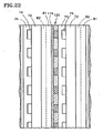
- a hydrophobic layer 114 is disposed between two hydrophilic layers 115, 116; the layers being disposed between the oxidant reactant gas flow field plate 81 of one fuel cell and the fuel reactant gas flow field plate 75 of a fuel cell adjacent thereto.
- the hydrophilic layers 115, 116 allow for in-plane water distribution and the hydrophobic layer 114 provides a path for gas to collect and flow out through the vent 68 ( Fig. 1 ). If desired, a single hydrophilic layer 115 or 116 may be utilized rather than two hydrophilic layers.
- the single hydrophilic layer 115 should be adjacent to the oxidant reactant gas flow field plate 81; when the primary objective is assuring hydration of the proton exchange membrane in the unitized electrode assembly 72, the hydrophilic layer 116 should be adjacent to the fuel reactant gas flow field plate 75.
- the layers 114-116 may comprise porous carbon fiber layers of the type typically used for gas diffusion layers in fuel cells, with appropriate treatment to render them either hydrophilic or hydrophobic.
- a conductive porous hydrophilic layer 119 is adjacent to the oxidant reactant gas flow field plate 81, and a layer 120, which is both hydrophilic and hydrophobic is adjacent to the fuel reactant gas flow field plate 75.
- the hydrophobic/hydrophilic plate 120 may comprise porous conductive hydrophobic material 121 with a plurality of non-hydrophobic regions 122 therein.
- the non-hydrophobic regions 122 may be the same material as the rest of the plate 120, which however are treated to make them hydrophilic, such as with a coating of tin.
- the non-hydrophobic regions 122 may simply be passageways (e.g., punched holes through the material 121) to allow water to pass through the layer 120.
- the non-hydrophobic regions 122 may be hydrophilic, or may simply be passageways.
- a water coolant by which is meant a coolant which is substantially pure water.
- the embodiment of Fig. 20 has been described as having coolant channels in which one wall 111 of each channel 110 has been treated to be hydrophobic with respect to water coolant; if a coolant other than water is utilized, the walls 111 of channels 110 illustrated in Fig. 20 may be more accurately described as liquiphobic, which is defined herein as having an aversion for the coolant liquid, or lacking affinity for the coolant liquid.
- bipolar plates include at least one hydrophilic layer and at least one additional layer which has hydrophilic and/or hydrophobic regions.
- the bipolar plates may include a liquiphilic layer, and at least one additional layer having liquiphilic and liquiphobic regions.
- liquiphilic is defined herein as having an affinity for the liquid coolant, whether it be substantially pure water or otherwise.
- Gas tolerant coolant passageways may be configured in groupings, such as pairs or larger series of alternatively sized or shaped channels.
- a fuel reactant gas flow field plate 75 has wide channels 127 interspersed with narrow channels 128. As illustrated by the bubbles 131, 132, the gas follows the path of least resistance through the flow field, and the gas therefore preferentially travels through the wide channels 127, rather than the narrow channels 128.
- the channels could be formed in the oxidant-reactant gas flow field plates, if desired.
- a variation in the depth of the channels causes the gas to have a proclivity for channels 135 which are deeper than channels 136 extending from the second surface 91 of the fuel reactant gas flow field plates 75.
- channels 139 that are rectangular may be interspersed with channels 140 which are triangular.
- the gas will have a proclivity for the triangular channels, thus assuring a water flow within the channels 139.
- the water flow in the channels for which the gas does not have a proclivity will create a pressure drop across the flow field plate thereby urging the gas bubbles to migrate toward the exit 142 ( Fig. 24 ) of the flow field plate 75.
- the likelihood that gas will become trapped only in every other channel will minimize the distance required for in-plane transfer of water within the reactant gas flow field plates.
- the deep/shallow combination of Fig. 25 may well be triangular, rather than rectangular; or some may be circular.
- divergent coolant channels 152 extend inwardly from the surface 93 of the oxidant reactant gas flow field plate 81 and are closed off by mating with the first surface 91 of the fuel reactant gas flow field plate 75.
- the channels 152 may have a square cross section as shown in Fig. 27 , or may have any other cross section, so long as the channels diverge in the direction of flow, diverging from inlet ends 156 of the channels 152 to outlet ends 157 of the channels 152, as illustrated in Fig. 28 . If the channels 152 have other than a round cross section, the cross section of the bubble 154 will not be round. Depending on the amount of gas in the bubble and the cross sectional area of the channel at any point, the bubble may tend to have a cross section in the direction of flow which is bean-shaped, as illustrated in Fig. 28 .
- the bubble 154 At any position where the bubble 154 is located within the channel, it will try to restore itself to a fully spherical shape, so that elements of the bubble nearer to the exit of the channel will expand, drawing the tail of the bubble along with it, and the bubble will creep toward the channel exit in its search of a spherical shape, seeking to minimize its surface energy.
- a perfectly spherical bubble will be lubricated by liquid flowing in the coolant channel and will readily flow therein toward the exit.
- the diverging channels may each be formed with one edge orthogonal to the edges of the flow plate, and the divergence all created by the angle of a second wall with respect to the edges of the flow plate.
- the passageways may be formed having a first wall at an angle to the edges of the flow plate and a second wall at an angle with respect to the edges of the flow plate which is greater than the angle of the first wall.
- the passageways may be serpentine, although it is preferred that the flow is against gravity, at least to some extent, in any portion of the diverging passageways.
- the movement of the bubble will be due to the following factors: (a) surface energy minimization causing it to move in a direction where the shape of the bubble will have the minimum surface energy (i.e., spherical); (b) buoyancy force - where the density difference between the lower density of the bubble and the higher density of the surrounding coolant will cause the bubble to move in a direction opposite to the gravitational force; and (c) the flow induced pressure on the bubble due to the coolant flow in the channel. Since any one of the forces listed above may be the dominant one, it may be possible to operate with different stack orientations.
- the exit for the bubble may not coincide with the exit for the coolant channels. In other words, the bubble may not move in the same direction as the coolant flow.
- the preferred embodiment has coolant flowing up, against gravity, and the bubble exit coincident with the coolant exit. The coolant flow up in the vertical direction with bubble exit coinciding with the coolant exit is the preferred embodiment.
Description
- Coolant passageway configuration reduces gas bubble blockage in small, low flow coolant passageways of fuel cells.
- In order to reduce the exposure of proton exchange membrane (PEM) fuel cells to problems resulting from freezing temperatures, and to reduce reliance on water pumps and other plumbing as accessories to the fuel cells, the total volume of coolant in the fuel cells may be reduced.
- However, in systems which do not use either a coolant pump or a gas venting micropump, and have minimal external water plumbing, the flow rate of coolant in the cells is quite low. If only gas is vented from the coolant passageways, water flow is limited to that which evaporates into the reactant gases. With small passageways and low water flow, gas bubbles may join together (aggregate) and block water flow from large areas of the water channels, sometimes referred to as "gas breakthrough" of the reactant gas flow field plates, thereby causing localized heating and dehydration of the membrane at various spots, resulting in degradation of components and reduced performance.
- Systems employing between-cell coolant plates, which have glycol or other coolants, may have extremely small, in-cell water passageways to provide low flows of water to the anode side of the fuel cells for hydration, with insignificant cooling resulting from the water flow.
- Coolant flow is assured in small fuel cell coolant passageways, mitigating bubble blockage of coolant flowing at a low flow rate in fuel cell coolant passageways; gas bubbles are assisted in flowing through coolant passageways of PEM fuel cells; venting of gas in PEM fuel cell coolant passageways is improved; flow of gas toward a vent is improved in PEM fuel cells; PEM fuel cell hydration is improved; and cooling is improved in PEM fuel cells.
- Although the ultimate purpose herein is to assure that coolant flow will not be blocked in small coolant passageways of a fuel cell, the removal of coolant-blocking gas bubbles is achieved by addressing the gas flow characteristics of the coolant passageways. The realization that gas, typically gas bubbles, present in small fuel cell coolant passageways having low coolant flow rates, may be propelled in properly designed passageways which assure sufficient flow of coolant through the coolant passageways to the vents, thereby ensuring an adequate flow of coolant for operational purposes, rather than blockage of coolant by gas bubbles.
- As coolant flow passageways become smaller, they become more prone to being blocked by bubbles of any gas therein. For a given cross sectional area of a prior art coolant passageway, there is a threshold coolant flow rate at or below which bubbles will block the coolant passageways if gas is present in the coolant; at coolant flow rates above the threshold, bubbles will be swept along by the flow of coolant, and will not block the coolant passageway.
- As used herein, the term "fuel cell" may mean the apparatus for a complete, operative fuel cell capable of producing electricity from oxidant and fuel reactant gases, or where the context so requires, that term may mean the portion of a fuel cell exclusive of layers that provide coolant to the fuel cells, which may be disposed between adjacent ones of said fuel cell portions.
- As used herein, the term "liquid coolant" means a coolant which is in the liquid state when the fuel cell is operating, even though such liquid coolant may freeze and become a solid when the fuel cell is not operating and the ambient temperature is below the freezing point of the coolant. The coolant may be water or other liquid; herein, "liquiphobic" is defined as having an aversion to the coolant, or lacking an affinity for the coolant, and "liquiphilic" is defined as having an affinity for, or lacking an aversion to, the coolant. The coolant flow assisted herein may, in some cases, be used primarily for hydration, with minimal cooling effect. Coolant flow paths and passageways herein are distinct from fuel and oxidant reactant gas flow field channels.
- As used herein, the term "coolant passageways" refers to those portions of the coolant flow path in a fuel cell stack which are substantially coextensive with the planform (the in-plane outline) of the fuel cells.
- Accordingly, gas tolerant coolant passageways of fuel cells promote flow of coolant within such passageways with or without the presence of gas. The gas tolerant configurations are provided along substantially the entire length of coolant passageways, thereby to provide a contiguous gas flow capability from inlets of said passageways to outlets thereof.
- In one form, gas tolerant fuel cell coolant passageways are configured to provide portions for which gas has an affinity, that is, a propensity to migrate to such portions and to flow therein, in contrast with other portions of the passageways where coolant may flow without interference from gas, thereby to assure that there is room for coolant to flow without being blocked by gas bubbles.
- Further, coolant passageways having gas tolerant cross sections may comprise first portions conducive to presence of gas preferentially in comparison with second portions which are less conducive to the presence of gas than the first portions.
- Gas tolerant passageways herein may comprise first and second portions within the same passageways: the first portions may be adjacent to a wall of a passageway which is liquiphobic; the first portions may each comprise a corner which subtends more than 90° between two walls of a passageway; the first portions may comprise a portion of a triangle, a trapezoid or other polygon away from acute angular areas thereof; or they may comprise combinations of the foregoing.
- In one form, the gas bubbles in the coolant channel are caused to be metastable by water channels which are diverging, that is which have a cross section of incrementally increasing size at corresponding incrementally increasing distances from the inlet of each channel. The bubble seeks to minimize its surface energy by seeking out a position in the channel where it will more closely approach having a spherical form. Diverging channels cause the metastable bubbles to move in the direction toward the exit of the channel, which is the direction of water flow, ensuring that blockage of water flow as a result of gas in the channel will be minimized.
- The flow of coolant is the purpose, rather than the flow of gas; however, the control of gas flow is accomplished by affecting the characteristics of the coolant channels with respect to gas: that is, while the coolant flow characteristics at low flow rates are essentially the same in one portion of the gas tolerant coolant passageways as in other portions thereof, provides certain portions of gas tolerant channels are provided for which gas has an affinity. Therefore, affecting the flow of gas within the passageway accomplishes the flow of coolant within the passageway, whether or not gas is present.
- Further embodiments of the invention are set out in the following numbered paragraphs:
- 1. A fuel cell method characterized by:
- preventing gas bubbles (87, 99) from blocking coolant flowing in coolant flow paths (77, 85) of fuel cells prone to bubble blockage of coolant flowing at or below a threshold flow rate by providing coolant passageways substantially coextensive with planforms of said fuel cells which have configurations, along substantially the entire length of said coolant passageways, allowing flow of coolant below said threshold flow rate both (a) when gas is present in said passageways and (b) when gas is not present in said passageways.
- 2. A method according to
paragraph 1 characterized in that said step of providing comprises:- providing coolant passageways (77, 85) within said coolant flow path substantially coextensive with planforms of said fuel cells (a) within and/or (b) adjacent to reactant gas flow field plates (75, 81) of said fuel cells configured to allow flow of said coolant therein whether or not there is any gas in said passageways.
- 3. A method according to
paragraph 1 characterized in that said step of providing comprises:- providing said coolant passageways (77, 85) having first portions for which gas has a propensity to migrate and flow in preference over second portions of said passageways for which gas does not have such propensity.
- 4. A method according to
paragraph 1 characterized In that said step of providing comprises:- configuring said coolant passageways (77, 85) to provide first portions for which gas has a sufficient proclivity to segregate gas from coolant so that gas present in said passageways migrates to and flows in said first portions in preference to second portions of said passageways for which gas does not have said sufficient proclivity, thereby mitigating the blockage of said coolant passageways by gas bubbles.
- 5. A fuel cell stack (37) comprising:
- a plurality of fuel cells (36) having an electrode assembly (72) including an electrolyte having anode and cathode catalysts disposed on respective anode and cathode sides thereof, a fuel reactant gas flow field plate (75) having fuel reactant gas flow channels (74) extending from a first surface (90) thereof adjacent said anode side, and an oxidant reactant gas flow field plate (81) having oxidant reactant gas flow channels (82) extending from a first surface (92) thereof adjacent said cathode side, at least one of said flow field plates being porous and hydrophilic;
- characterized by:
- a coolant flow path configured to allow coolant flow, including at least one coolant passageway (77, 85) disposed in or near a second surface (91, 93) of at least one of said flow field plates of each fuel cell which is opposite to said first surface thereof, said coolant passageways each configured to provide a first portion for which gas has a sufficient affinity to cause gas to migrate to said first portion in preference to a second portion of each passageway.
- 6. A fuel cell stack (37) according to paragraph 5 characterized in that:
- said coolant passageways (77, 85) are configured to provide second portions for which gas does not have said sufficient affinity, thereby mitigating the blockage of said coolant passageways by gas bubbles.
- 7. A fuel cell stack (37) according to paragraph 5 characterized in that:
- said portions extend along substantially the entire lengths of said coolant passageways.
- 8. A fuel cell stack (37) according to paragraph 5 characterized in that:
- said first portions are first channels having a first cross section; and
- said second portions are second channels, having a second cross section different than said first cross section.
- 9. A fuel cell stack (37) according to paragraph 8 characterized In that:
- said second channels are smaller than said first channels.
- 10. A fuel cell stack (37) according to paragraph 8 characterized in that:
- said second channels are interspersed with said first channels.
- 11. A fuel cell stack (37) according to paragraph 8 characterized in that:
- said first channels are rectangular and said second channels are triangular.
- 12. A fuel cell stack (37) according to paragraph 8 characterized in that:
- said second channels are of different shape than said first channels.
- 13. A fuel cell stack (37) according to paragraph 5 characterized in that:
- each of said first portions is contiguous with one of said second portions.
- 14. A fuel cell stack (37) according to paragraph 5 characterized in that:
- each of said first portions (110) is adjacent a wall of a corresponding passageway which has a liquiphobic surface (111).
- 15. A fuel cell stack (37) according to paragraph 5 characterized in that:
- each of said first portions comprises a corner (98, 99) between two walls of a corresponding coolant passageway which subtends more than 90°.
- 16. A fuel cell stack (37) according to paragraph 15 characterized in that:
- said coolant passageways (77, 85) have a triangular cross section.
- 17. A fuel cell stack (37) according to paragraph 15 characterized in that:
- said coolant passageways (77, 85) have a trapezoidal cross section (96-99).
- 18. A fuel cell stack (37) according to paragraph 17 characterized in that:
- said trapezoidal passageways (96-99) have a longer one of two parallel sides in the same plane as said second surface (93).
- 19. A fuel cell stack (37) according to paragraph 5 characterized in that:
- said coolant passageways are provided by composite bipolar plates (114-116; 120) interspersed between said fuel cells (38).
- 20. A fuel cell stack (37) according to paragraph 19 characterized in that:
- each of said bipolar plates includes a liquiphilic layer (115, 116; 119) for contact with one of said reactant gas flow field plates (75, 81), and at least one additional layer (119; 114, 115, 116; 120) providing liquiphilic and liquiphobic portions between said liquiphilic layer and another one of said reactant gas flow field plates (81, 75).
- 21. A fuel cell stack (37) according to paragraph 20 characterized in that:
- said liquiphilic (115, 116, 119) and liquiphobic layers (114, 120) are hydrophilic or hydrophobic, respectively.
- 22. A fuel cell stack (37) according to paragraph 20 characterized in that:
- each said bipolar plate comprises two liquiphilic layers (115, 116) with a liquiphobic layer (114) between said two liquiphilic layers.
- 23. A fuel cell stack (37) according to paragraph 20 characterized in that:
- each said bipolar plate comprises a liquiphilic layer and a layer which has separate liquiphilic and liquiphobic portions.
- 24. A fuel cell stack (37) according to paragraph 5 characterized in that:
- said coolant passageways (77, 85) each include at least one first coolant channel (83) in one of said plates (81) and at least one second coolant channel (84) in another of said plates (75) adjacent to said one of said plates, said second coolant channels each aligned with a corresponding one of said first coolant channels.
- 25. A fuel cell stack (37) according to paragraph 24 characterized in that:
- said second coolant channels (84) have cross sectional areas substantially smaller than cross sectional areas of said first coolant channels (83).
- 26. A fuel cell stack (37) according to paragraph 24 characterized in that:
- said second coolant channels (84) have cross sections shaped differently than the cross sectional areas of said first coolant channels (83).
- 27. A fuel cell stack (37) according to paragraph 5 characterized in that:
- each of said passageways has a cross section comprised of at least two intersecting closed plane areas bounded by lines, said areas each having a cross section different from another one of said areas.
- 28. A fuel cell stack according to paragraph 27 characterized in that:
- one of said closed plane areas bounded by lines extends from said second surface (91, 93) of one of said plates (81, 75) and another of said closed plane areas bounded by lines extends from a second surface (93, 91) of another of said plates (75, 81) adjacent to said one plate.
- 29. A fuel cell stack (37) according to paragraph 27 characterized in that:
- both of said closed plane areas bounded by lines extend from said second (93) surface of one of said plates (81).
- 30. A fuel cell stack (37) according to paragraph 27 characterized in that:
- said closed plane areas bounded by lines are intersecting polygons.
- 31. A fuel cell stack (37) according to paragraph 30 characterized in that:
- one of said intersecting polygons is a rectangle.
- 32. A fuel cell stack (37) according to paragraph 30 characterized in that:
- two of said intersecting polygons are rectangles.
- 33. A fuel cell stack (37) according to paragraph 30 characterized in that:
- one of said intersecting polygons is a triangle.
- 34. A fuel cell stack (37) according to paragraph 5 characterized in that:
- said coolant passageways comprise coolant channels (102) extending from said second surface (93) of one of said flow field plates (81) and a layer (100) of material, highly permeable to coolant, disposed between and substantially coextensive with adjacent ones of said flow field plates (75, 81) in said stack.
- 35. A fuel cell stack (37) according to paragraph 34 characterized in that:
- said channels are either (a) substantially rectangular (102) or (b) shaped to have a gas tolerant cross section.
- 36. A fuel cell stack (37) according to paragraph 5 characterized in that:
- the cross section of each of said passageways comprises the intersection of a first groove, extending from said second surface of said fuel reactant gas flow field plate and a second groove, smaller than said first groove, extending from said first groove toward said first surface of said fuel reactant gas flow field plate.
- 37. A fuel cell stack (37) according to paragraph 5 characterized in that:
- said coolant passageways are at least one of (a) within reactant gas flow field plates and (b) adjacent to reactant gas flow field plates.
- 38. A fuel cell stack (37) comprising:
- a plurality of fuel cells (38) having reactant gas flow field plates (75, 81);
- a coolant flow path (77, 85) extending to a plurality of fuel cells in said stack; and
- coolant passageways within said coolant flow path substantially coextensive with planforms of said fuel cells and at least one of (a) within said reactant gas flow field plates and (b) adjacent to said reactant gas flow field plates;
- characterized by:
- said coolant passageways configured to provide portions with high capillary pressure extending along substantially the entire length of said passageways.
- 39. A fuel cell method characterized by:
- preventing gas bubbles (87, 99, 131, 132) from blocking liquid coolant flowing in coolant flow paths (77, 85) of fuel cells (38), at or below a bubble blockage threshold flow rate below which bubble blockage of coolant may occur, by providing liquid coolant flow passageways substantially coextensive with planforms of said fuel cells which are configured, along the length of said liquid coolant flow passageways, to flow liquid coolant below said bubble blockage threshold flow rate.
- 40. A method according to paragraph 39 characterized In that
- said providing step comprises providing said liquid coolant flow passageways configured to flow liquid coolant in the presence of gas below said threshold bubble blockage flow rate.
- 41. A method according to paragraph 39 characterized in that:
- said providing step comprises providing said liquid coolant flow passageways configured to flow liquid coolant below said threshold bubble blockage flow rate both (a) when gas is present in said passageways and (b) when gas is not present in said passageways.
- 42. A method according to paragraph 39 characterized in that:
- said providing step comprises providing said liquid coolant flow passageways configured along substantially the entire length of said liquid coolant flow passageways to flow liquid coolant below said threshold bubble blockage flow rate.
- 43. Fuel cell apparatus (37), comprising:
- a plurality of fuel cells (38), each having a planform;
- characterized by:
- liquid coolant flow passageways (77, 85), substantially coextensive with said planforms of said fuel cells, said liquid coolant flow passageways configured along the length of said liquid coolant flow passageways to flow liquid coolant below a threshold bubble blockage flow rate whereby gas bubbles are prevented from blocking liquid coolant flowing in said fuel cell liquid coolant flow passageways with liquid coolant flowing at or below said threshold flow rate.
- 44. Apparatus (37) according to
paragraph 43 characterized in that:- said liquid coolant flow passageways (77, 85) are configured to flow liquid coolant below said threshold bubble blockage flow rate both (a) when gas is present in said passageways and (b) when gas is not present in said passageways.
- 45. Apparatus (37) according to
paragraph 43 characterized in that:- said liquid coolant flow passageways (77, 85) are configured along substantially the entire length of said liquid coolant flow passageways to flow liquid coolant below said threshold bubble blockage flow rate.
- 46. A fuel cell stack (37) comprising:
- a plurality of fuel cells (38) having cell assemblies (78) including an electrolyte having an anode and a cathode disposed on respective anode and cathode sides thereof, a fuel reactant gas flow field plate (75) having fuel reactant gas flow channels (74) extending from a first surface (90) thereof adjacent said anode side, and an oxidant reactant gas flow field plate (81) having oxidant reactant gas flow channels (81) extending from a first surface (82) thereof adjacent said cathode side, at least one of said flow field plates being porous and hydrophilic;
- characterized by:
- a coolant flow path configured to allow liquid coolant flow, including at least one coolant passageway (77, 85) disposed in or near a second surface (91, 93) of at least one of said flow field plates of each fuel cell, said coolant passageways each having an inlet end (156) and an outlet end (154), each of said passageways formed by a channel (152) which diverges from said inlet end to said outlet end.
- 47. A fuel cell stack (37) comprising:
- a plurality of fuel cells (38) having cell assemblies (78) including an electrolyte having an anode and a cathode disposed on respective anode and cathode sides thereof, a fuel reactant gas flow field plate (75) having fuel reactant gas flow channels (74) extending from a first surface (90) thereof adjacent said anode side, and an oxidant reactant gas flow field plate (81) having oxidant reactant gas flow channels (82) extending from a first surface thereof (92) adjacent said cathode side, at least one of said flow field plates being porous and hydrophilic;
- characterized by:
- a coolant flow path configured to allow liquid coolant flow, including at least one coolant passageway (152) disposed in or near a second surface (93) of at least one of said flow field plates of each fuel cell, said coolant passageways each having an inlet end (156) and an outlet end (157), configured to provide, at any point between said ends, a first portion toward said outlet end from said point for which gas has a sufficient affinity to cause gas to migrate to said first portion in preference to a second portion of each passageway toward said inlet end from said point.
- 48. A fuel cell stack (39) according to paragraph 9 characterized in that:
- said coolant passageways (152) diverge from said inlet ends (156) to said outlet ends (157) along substantially the entire lengths of said coolant passageways.
- Other features and advantages will become more apparent in the light of the following detailed description of exemplary embodiments thereof, as illustrated in the accompanying drawings.
-
-
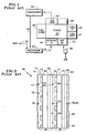
Fig. 1 is a simplified, stylized block diagram of an evaporatively cooled fuel cell system, which may.be modified to employ gas tolerant coolant flow. -
Fig. 2 is a partial, sectioned side elevation view of a pair of fuel cells employing minute water passageways, with the sectioning lines omitted for clarity. -
Fig. 3 is a partial, sectioned, side elevation view of a pair of fuel cells employing gas tolerant coolant channels, with the sectioning lines omitted for clarity. -
Figs. 4-9 are fragmentary, sectioned, side elevation views of gas tolerant coolant channels, with the portion for which gas has a proclivity oriented toward the fuel reactant gas flow fields as follows:-
Fig. 4 - intersecting rectangles formed in adjoining plates; -
Fig. 5 - intersecting rectangles formed in the oxidant reactant gas flow field plate; -
Fig. 6 - triangle formed in the oxidant reactant gas flow field plate; -
Fig. 7 - intersecting rectangle and triangle formed in adjoining plates; -
Fig. 8 - intersecting triangle and rectangle formed in the fuel reactant gas flow field plates; -
Fig. 9 - trapezoid formed in the oxidant reactant gas flow field plate;
-
-
Figs. 10-15 are respective variants ofFigs. 4-9 , with the portion of the coolant passageway for which gas has a proclivity oriented toward the oxidant reactant gas flow fields. -
Fig. 16 is a partial, sectioned, side elevation view of a pair of fuel cells employing a layer highly permeable to coolant with adjacent coolant channels. -
Fig. 17 is a fragmentary expanded view of the channels and layers ofFig. 16 . -
Figs. 18 and 19 are fragmentary views of intersecting rectangles and triangles associated with the highly permeable layer ofFig. 16 . -
Fig. 20 is a fragmentary, sectioned, side elevation view of a coolant channel having one hydrophobic wall. -
Fig. 21 is a partial, sectioned, side elevation view of a pair of fuel cells employing hydrophilic and hydrophobic layers between adjacent reactant gas flow field plates. -
Fig. 22 is partial, sectioned, side elevation view of a pair of fuel cells employing a hydrophilic layer adjacent a hydrophilic/hydrophobic layer disposed between adjacent reactant gas flow field plates. -
Fig. 23 is a plan view of a hydrophilic/hydrophobic layer ofFig. 22 . -
Fig. 24 is a plan view of adjacent narrow and wide coolant channels. -
Figs. 25 and 26 are partial, sectioned, side elevation views of a pair of fuel cells embodying variants of the form shown inFig. 24 . -
Fig. 27 is a partial, sectioned, side elevation view of a pair of fuel cells employing divergent coolant channels. -
Fig. 28 is a side elevation view of divergent coolant channels ofFig. 27 . - A fuel cell system employing evaporative cooling is disclosed in
U.S. Serial No. 11/230,066 filed September 19, 2005 US2006-0141331 and described with respect toFigs. 1 and 2 herein. In the aforementioned application, water evaporates into air, pumped 52 through anair inlet 53, within the oxidant reactant gas (air) flow fields in thestack 37 thereby cooling the fuel cells 38 (Fig. 2 ). Theoutflow 57 of the oxidant reactant gas channels passes through acondenser 59 wherein heat is removed and the water is recovered and returned over aconduit 60 to a water/gas separator 64 which also serves as a reservoir. Any gas separated from the water is removed throughexhaust 62, the water returning via aconduit 65 and acoolant inlet 66 to the water passageways in thestack 37 and upward toward anoutlet 68. - In
Fig. 2 ,fuel cells 38 each comprise a conventionalmembrane electrode assembly 72, which includes an electrolyte with anode and cathode catalysts on opposite sides thereof and may include a gas diffusion layer on one or both electrodes. Fuel reactant gas flows throughchannels 74 in a fuel reactant gasflow field plate 75 havinggrooves 76, which together withgrooves 77 of an adjacent fuel cell, formminute water passageways 78 at ajuncture 79 of thefuel cells 38. On the cathode side, an oxidant reactant gasflow field plate 81 includesair flow channels 82 andgrooves 83 which, withgrooves 84 on an adjacent fuel cell, together formminute water passageways 85 at ajuncture 86 of the fuel cells. - To prevent flooding, pressure of water in the passageways is between one and ten Kilopascals lower than the pressure of the reactant gases, such as provided by an air pump and pressure-regulated fuel.
- The passageways may be formed other than by matching grooves as shown, such as by
channels flow field plates - The reactant gas
flow field plates U.S. patent 5,700,595 . However, because there is about a 40 times improvement in cooling effectiveness per volume of water when evaporative cooling is used, the water flow channels of the aforesaid '595 patent have cross sections which are several tens of times larger than the cross sections of thewater passageways Fig. 2 . - In another embodiment of the aforementioned patent application, there is a material which is conductive, hydrophilic and has a high permeability to water, extending over substantially the entire planform of the reactant gas
flow field plates grooves forming passageways - The water passageways are typically very small and capable of providing the water required for evaporative cooling. Water flow in addition to that needed for evaporative cooling can assist in removing gas bubbles which leak in from the reactant gas channels, and may assist in deionizing (demineralizing) water which is circulating in the system. Such water flow can be adequate if provided by a pump and plumbing external to the fuel cells.
- Herein, that portion of fuel cell coolant paths which are substantially coextensive with the general planform of the fuel cells comprise gas tolerant coolant passageways, such as the
passageways Figs. 3 and 4 . The general planforms of fuel cells are normal toFigs. 2-22 , and are illustrated (in specific forms) inFigs. 23 and 24 . Gastolerant coolant passageways rectangular channels surface 91 of the fuel reactant gasflow field plates 75, opposite to asurface 90 from which the fuelflow field channels 74 extend, andchannels channels channels surface 93 of the oxidant reactant gasflow field plate 81 which is opposite to asurface 92 from which the oxidantreactant gas channels 82 extend. This is one embodiment of gas tolerant coolant channels comprising intersecting closed plane figures, such as polygons. - There is a tendency for any gas within the
passageways larger rectangles smaller rectangles bubble 87, the first portion of the coolant passageways formed by thelarge rectangles small rectangles larger rectangles smaller rectangles smaller rectangles - As a result of the flow of coolant in the
smaller rectangles larger rectangles Fig. 1 ), assuring that the bubbles will not aggregate to the extent that theentire channels - As illustrated in
Fig. 5 , thechannels flow field plates 81, extending from thesurface 93 thereof, rather than two rectangles separately made in the fuel reactant gasflow field plates 75 and in the oxidant reactant gasflow field plate 81, as inFig. 4 . - Another form, illustrated in
Fig. 6 , provides gastolerant coolant channels 85 which are triangular in shape. In the embodiment ofFig. 6 , an isosceles triangle is shown with its base in the same plane as the plane of thesurface 93. In this embodiment, theacute angles surface 93 are smaller than theobtuse angle 98 away from the surface, and the bubbles tend to aggregate near theobtuse angle 98, as illustrated by thebubble 99. As is seen by thebubble 99, the gas has a proclivity to collect in the portions of thecoolant passageways 85 adjacent to theobtuse angles 98 preferentially in comparison with theacute angles coolant passageways 85. This means that the coolant can flow readily away from theapexes 98 of thechannels 85, closer to the fuel reactant gasflow field plates 75. In the embodiment ofFig. 6 , with coolant flowing adjacent to the fuel reactant gasflow field plates 75, humidification of the anode side of the unitizedelectrode assembly 72 is assured. - The triangular cross sections of the gas
tolerant coolant passageways 85 may be equilateral, or they may be either scalene or isosceles right triangles. Or, they may be scalene triangles other than right triangles. However, since the gas will tend to migrate toward and/or remain in large, obtuse corners, in preference over small, acute corners, an equilateral triangle is probably not as useful as one in which theangles surface 93 are acute and smaller than the apex 98 away from thesurface 93; the apex in such case is greater than 180°/N. Capillary flow may occur in a corner of a liquid passageway if
- In the general case, this form will have one angular intersection of sides of the coolant channel which has an angle greater than 180°/N, where N is the total number of sides (including an open portion substantially in the plane of one of the
surfaces 91, 93). Thus, one of the angles of a triangular passageway, typically the apex, will be greater than 60°. - Referring to
Fig. 7 , atriangular channel 84 extends from thesurface 91 of the fuel reactant gasflow field plate 75, intersecting with arectangle 83 extending from thesurface 93 of the oxidant reactant gasflow field plate 81. In this case, bubbles will collect in thetriangular channels 84, allowing coolant to flow freely in therectangular channels 83, the flow sweeping the bubbles along toward the vent 68 (Fig. 1 ). -
Fig. 8 illustrates that atriangle 84 intersecting with arectangle 83 may both extend from theedge 91 of the fuel reactant gasflow field plate 75. Although the embodiments ofFigs. 3-8 comprise intersecting polygons, in the general case, the gas tolerant coolant passageways may have cross sectional areas which comprise the intersection of two closed plane figures bounded by other than straight lines (having at least some curvilinear boundaries) as well as closed plane figures bounded by straight lines (polygons). -
Fig. 9 illustrates that the gastolerant coolant channels 85 may have a trapezoidal cross section. In such a case, the gas tends to migrate or remain away from theacute angles surface 93 of the oxidant reactant gasflow field plates 81. Coolant is free to flow near the acute angle portions of the trapezoidal cross section, and the flow of coolant sweeps the gas bubbles along toward the vent 68 (Fig. 1 ). Theobtuse angles - In
Figs. 4-9 , there are first portions of the gas tolerant coolant passageways, such as thelarge rectangles 83 ofFig. 4 or the obtuse angles of thetriangular passageways 85 ofFig. 6 , to or in which the gas will migrate and/or flow, preferentially to second portions, such as the small rectangle ofFig. 4 or the acute angles of the triangular shaped gastolerant coolant passageways 85 inFig. 6 , or the trapezoid ofFig. 9 . The gas has an affinity for the first portions which allows coolant to flow, unfettered by bubbles, in the second portions. In this form, the water or other coolant will flow at a low flow rate in large or small channels and in corners or other parts of passageways; but to ensure that flow, the gas must be segregated to first portions of the passageways so that within the second portions of the passageways, which are less preferential to the migration or retention of gas bubbles, the water or other coolant will flow unimpeded by bubbles to achieve product water removal, hydration and/or evaporative cooling as required, while at the same time sweeping the bubbles toward the vent. - In the general case, gas tends to leak from the fuel reactant gas flow field plate into the coolant passageways of a fuel cell. For that reason, the portions of gas tolerant coolant passageways for which the gas has an affinity might preferably be disposed toward the fuel reactant gas flow field plate, whereas those portions of gas tolerant coolant passageways which are less conducive to gas bubbles will be positioned toward the oxidant reactant gas flow field plate. In the case of gas tolerant water passageways utilized in evaporatively cooled fuel cells, this assures that water will easily reach and be evaporated into the oxidant reactant gas
flow field channels 82. - Each of
Figs. 10-15 respectively corresponds to one ofFigs. 4-9 and illustrates that the configuration can be reversed from that illustrated inFigs. 4-9 so as to provide the first portions to which or in which the gas preferentially migrates or remains is closer to the oxidant reactant gas flow field channels, whereas the second portion, which is less preferential to the gas, and thereby assures the presence and flow of water, is toward the fuel reactant gas flow field channels. The embodiments illustrated inFigs. 10-15 are useful in fuel cell stacks wherein humidification of the anode side of the proton exchange membrane is of paramount concern. These are useful, for instance, in fuel cell power plants wherein the stack is cooled by means of coolant plates having a non-freezable coolant, such as a water glycol mixture, but water is circulated adjacent to the fuel reactant gas flow field plates to humidify the proton exchange membrane. - Referring to
Fig. 16 , a pair offuel cells 38a have gas tolerant coolant passageways which include a porous,conductive layer 100 that is highly permeable to water, disposed adjacent to the entire active area of the planform of the fuel reactant gas flow field plate. Coolant passageways also comprise channels, such asrectangular channels 102 preferably extending from thesurfaces 93 of the oxidant reactant gasflow field plates 81 which are opposite to thesurfaces 92 from which the oxidant reactant gasflow field channels 82 extend. However, if desired in any given case, the channels could extend from the surfaces of the fuel reactant gas flow field plates. Thepermeable layer 100 may be formed of wettable carbon fiber paper, such as the commonly used TORAY® paper, which has been treated with tin in a conventional manner. Some fuel cell stacks have high ingestion of gas into the fuel reactant gas channels, which the porous layer helps to prevent. - Although a gas bubble may form in one of the
channels 102 thereby tending to block water in that channel, the highlypermeable layer 100 will conduct water, freely, around the bubble-blocked channel, fromother channels 102 to the entire planform of the fuel reactant gasflow field plates 75. The water flows faster within the permeable layer 106 than inchannels 102, and causes a pressure drop from the coolant inlet to the vent 68 (Fig. 1 ) which will propel bubbles in thechannels 102 along toward thevent 68. - Thus, the highly
permeable layer 100 is disposed between the oxidant reactant gas flow field plate of each fuel cell and the fuel reactant gas flow field plate of the fuel cell adjacent thereto in said stack; of course, the highly permeable layer adjacent to the oxidant reactant gas flow field plate in a fuel cell which is at the cathode end of the stack will not be adjacent, in the usual case, to any fuel reactant gas flow field plate. As used herein, the term "each fuel cell" excludes the last fuel cell at the cathode end of the stack, which has a highly permeable layer next to its oxidant reactant gas flow field plate, but that layer is not typically adjacent to any fuel reactant gas flow field plate, there being none beyond the last fuel cell at the cathode end of the stack. - In addition, the highly
permeable layer 100 allows water to move rapidly around any bubble that may be blocking an adjacent water channel. This prevents local dry-out of the fuel gas flow field plate, thereby avoiding "breakthrough, which allows gas to pass freely through the flow field plate. In this way, thelayer 100 substantially "blocks" the flow of reactant gas from the fuel reactant gasflow field channels 74 and the oxidant reactant gasflow field channels 82 to thewater passageways 102. Thus, the formation of gas bubbles within thecoolant water passageways 102 is reduced, and the effect of such bubbles, in blocking water from various parts of a fuel cell planform, is also reduced. - In
Fig. 16 , thewater passageways 102 are rectangular, as illustrated in a larger form inFig. 17 , becausepassageways 102 of rectangular cross section are readily utilized without gas bubble problems when the highlypermeable layer 100 is utilized adjacent to thepassageways 102. - However, if deemed necessary in any given utilization of the highly
permeable layer 100, such as in the case of desiring to havewater passageways 102 of extremely small cross section, the cross section of thewater passageways 102 may provide additional gas tolerance. For instance, a channel configuration illustrated inFig. 18 has a firstrectangular groove 107 extending from thesecond surface 93 of the oxidant reactant gasflow field plate 81 and a secondrectangular groove 108, smaller than the first groove, extending from the firstrectangular groove 107 toward thefirst surface 92 of the oxidant reactant gasflow field plate 81. This configuration will permit gas bubbles to form and perhaps to aggregate with other bubbles to make larger bubbles in thechannels 107, while thegroove 108, being less conducive to gas migration and retention, provides for a contiguous water path throughout the planform of each fuel cell, as described with respect toFigs. 3 and 4 hereinbefore. - The passageways may be triangular, as shown by the
passageway 102b inFig. 19 . The base of the triangle is in a plane coextensive with thesecond surface 93 of the oxidant reactant gasflow field plate 81. This configuration, having two acute angles and an obtuse angle causes gas to flow in the small angles, allowing free flow of water in the areas remote from the obtuse angle, as described with respect toFig. 6 hereinbefore. - The water passageways can be of other configurations since employment of the highly
permeable layer 100 avoids the problem of water passageways being blocked by air bubbles when there is a very low flow rate of water. - Another configuration, illustrated in
Fig. 20 , employs gas tolerant coolant channels of which onewall 111 has been treated to be hydrophobic, as indicated by the stippling. InFig. 20 , the wall that is treated is parallel to the plane of thesecond surface 91 of the fuel reactant gasflow field plate 75. However, the hydrophobicity may be applied to any other wall of thechannel 110, if desired, to suit any implementation of gas-tolerant coolant flow paths. InFig. 20 , thechannel 110 is rectangular; however, it may be some other shape if desired, such as to suit ease of manufacture in the implementation of gas-tolerant coolant flow paths. - Another configuration employs layers which are conductive, highly permeable to water, and including hydrophilicity and hydrophobicity. In one embodiment illustrated in
Fig. 21 , ahydrophobic layer 114 is disposed between twohydrophilic layers flow field plate 81 of one fuel cell and the fuel reactant gasflow field plate 75 of a fuel cell adjacent thereto. Thehydrophilic layers hydrophobic layer 114 provides a path for gas to collect and flow out through the vent 68 (Fig. 1 ). If desired, a singlehydrophilic layer hydrophilic layer 115 should be adjacent to the oxidant reactant gasflow field plate 81; when the primary objective is assuring hydration of the proton exchange membrane in the unitizedelectrode assembly 72, thehydrophilic layer 116 should be adjacent to the fuel reactant gasflow field plate 75. - The layers 114-116 may comprise porous carbon fiber layers of the type typically used for gas diffusion layers in fuel cells, with appropriate treatment to render them either hydrophilic or hydrophobic.
- In another embodiment illustrated in
Figs. 22 and23 , a conductive poroushydrophilic layer 119 is adjacent to the oxidant reactant gasflow field plate 81, and alayer 120, which is both hydrophilic and hydrophobic is adjacent to the fuel reactant gasflow field plate 75. - The hydrophobic/
hydrophilic plate 120 may comprise porous conductivehydrophobic material 121 with a plurality ofnon-hydrophobic regions 122 therein. Thenon-hydrophobic regions 122 may be the same material as the rest of theplate 120, which however are treated to make them hydrophilic, such as with a coating of tin. On the other hand, thenon-hydrophobic regions 122 may simply be passageways (e.g., punched holes through the material 121) to allow water to pass through thelayer 120. Thus, thenon-hydrophobic regions 122 may be hydrophilic, or may simply be passageways. - The concepts have been described with respect to fuel cells employing a water coolant, by which is meant a coolant which is substantially pure water. The embodiment of
Fig. 20 has been described as having coolant channels in which onewall 111 of eachchannel 110 has been treated to be hydrophobic with respect to water coolant; if a coolant other than water is utilized, thewalls 111 ofchannels 110 illustrated inFig. 20 may be more accurately described as liquiphobic, which is defined herein as having an aversion for the coolant liquid, or lacking affinity for the coolant liquid. - In
Figs. 21 and22 , bipolar plates include at least one hydrophilic layer and at least one additional layer which has hydrophilic and/or hydrophobic regions. In the general case, the bipolar plates may include a liquiphilic layer, and at least one additional layer having liquiphilic and liquiphobic regions. The term liquiphilic is defined herein as having an affinity for the liquid coolant, whether it be substantially pure water or otherwise. - Gas tolerant coolant passageways may be configured in groupings, such as pairs or larger series of alternatively sized or shaped channels. In one embodiment illustrated in
Fig. 24 , a fuel reactant gasflow field plate 75 haswide channels 127 interspersed withnarrow channels 128. As illustrated by thebubbles wide channels 127, rather than thenarrow channels 128. The channels could be formed in the oxidant-reactant gas flow field plates, if desired. - In another embodiment illustrated in
Fig. 25 , a variation in the depth of the channels causes the gas to have a proclivity forchannels 135 which are deeper thanchannels 136 extending from thesecond surface 91 of the fuel reactant gasflow field plates 75. - In
Fig. 26 , another embodiment illustrateschannels 139 that are rectangular may be interspersed withchannels 140 which are triangular. The gas will have a proclivity for the triangular channels, thus assuring a water flow within thechannels 139. - In the embodiments of
Figs. 24-26 , the water flow in the channels for which the gas does not have a proclivity will create a pressure drop across the flow field plate thereby urging the gas bubbles to migrate toward the exit 142 (Fig. 24 ) of theflow field plate 75. In the embodiments ofFigs. 24-26 , the likelihood that gas will become trapped only in every other channel will minimize the distance required for in-plane transfer of water within the reactant gas flow field plates. Various other combinations may be utilized: for instance, the deep/shallow combination ofFig. 25 may well be triangular, rather than rectangular; or some may be circular. - In
Figs. 27 and 28 ,divergent coolant channels 152 extend inwardly from thesurface 93 of the oxidant reactant gasflow field plate 81 and are closed off by mating with thefirst surface 91 of the fuel reactant gasflow field plate 75. Thechannels 152 may have a square cross section as shown inFig. 27 , or may have any other cross section, so long as the channels diverge in the direction of flow, diverging from inlet ends 156 of thechannels 152 to outlet ends 157 of thechannels 152, as illustrated inFig. 28 . If thechannels 152 have other than a round cross section, the cross section of the bubble 154 will not be round. Depending on the amount of gas in the bubble and the cross sectional area of the channel at any point, the bubble may tend to have a cross section in the direction of flow which is bean-shaped, as illustrated inFig. 28 . - At any position where the bubble 154 is located within the channel, it will try to restore itself to a fully spherical shape, so that elements of the bubble nearer to the exit of the channel will expand, drawing the tail of the bubble along with it, and the bubble will creep toward the channel exit in its search of a spherical shape, seeking to minimize its surface energy. A perfectly spherical bubble will be lubricated by liquid flowing in the coolant channel and will readily flow therein toward the exit.
- The diverging channels may each be formed with one edge orthogonal to the edges of the flow plate, and the divergence all created by the angle of a second wall with respect to the edges of the flow plate. The passageways may be formed having a first wall at an angle to the edges of the flow plate and a second wall at an angle with respect to the edges of the flow plate which is greater than the angle of the first wall. The passageways may be serpentine, although it is preferred that the flow is against gravity, at least to some extent, in any portion of the diverging passageways.
- The movement of the bubble will be due to the following factors: (a) surface energy minimization causing it to move in a direction where the shape of the bubble will have the minimum surface energy (i.e., spherical); (b) buoyancy force - where the density difference between the lower density of the bubble and the higher density of the surrounding coolant will cause the bubble to move in a direction opposite to the gravitational force; and (c) the flow induced pressure on the bubble due to the coolant flow in the channel. Since any one of the forces listed above may be the dominant one, it may be possible to operate with different stack orientations. In some implementations, the exit for the bubble may not coincide with the exit for the coolant channels. In other words, the bubble may not move in the same direction as the coolant flow. The preferred embodiment has coolant flowing up, against gravity, and the bubble exit coincident with the coolant exit. The coolant flow up in the vertical direction with bubble exit coinciding with the coolant exit is the preferred embodiment.
- Although the foregoing embodiments are described as they may be used in conjunction with an evaporatively cooled fuel cell power plant of the type described with respect to
Fig. 1 herein, they may be employed in a wide variety of fuel cell systems. Examples include systems described in the aforementioned US publication. For instance, the embodiments herein may be used in fuel cell stacks in which the coolant passageways are dead ended, having no channel outlet, and relying on flow of bubble gas from the coolant, through porous water transport plates and into reactant streams.
Claims (15)
- A fuel cell method characterized by:preventing gas bubbles (87, 99, 131, 132) from blocking liquid coolant flowing in coolant flow paths (77, 85) of fuel cells (38), at or below a bubble blockage threshold flow rate below which bubble blockage of coolant may occur, by providing liquid coolant flow passageways substantially coextensive with planforms of said fuel cells the cross sections of which are configured, along the length of said liquid coolant flow passageways, to provide a first portion for which gas has a sufficient affinity to cause gas to migrate to said first portion in preference to a second portion of each passageway.
- A method according to claim 1 characterized in that said step of providing comprises:providing the cross sections of said coolant passageways (77, 85) having first portions for which gas has a propensity to migrate to and flow in preference over second portions of said passageways for which gas does not have such propensity.
- A method according to claim 1 characterized in that said step of providing comprises:configuring the cross sections of said coolant passageways (77, 85) to provide first portions for which gas has a sufficient proclivity to segregate gas from coolant so that gas present in said passageways migrates to and flows in said first portions in preference to second portions of said passageways for which gas does not have said sufficient proclivity, thereby mitigating the blockage of said coolant, passageways by gas bubbles.
- A fuel cell stack (37) comprising:a plurality of fuel cells (36) having an electrode assembly (72) including an electrolyte having anode and cathode catalysts disposed on respective anode and cathode sides thereof, a fuel reactant gas flow field plate (75) having fuel reactant gas flow channels (74) extending from a first surface (90) thereof adjacent said anode side, and an oxidant reactant gas flow field plate (81) having oxidant reactant gas flow channels (82) extending from a first surface (92) thereof adjacent said cathode side, at least one of said flow field plates being porous and hydrophilic;characterized by:a coolant flow path configured to allow coolant flow, including at least one coolant passageway (77, 85) disposed in or near a second surface (91, 93) of at least one of said flow field plates of each fuel cell which is opposite to said first surface thereof, the cross section of said coolant passageways each configured to provide a first portion for which gas has a sufficient affinity to cause gas to migrate to said first portion in preference to a second portion of each passageway.
- A fuel cell stack (37) according to claim 4 characterized in that:said first portions are first channels having a first cross section; andsaid second portions are second channels, having a second cross section different than said first cross section.
- A fuel cell stack (37) according to claim 4 or 5 characterized in that:said second channels are interspersed with said first channels.
- A fuel cell stack (37) according to any of claim 4 to 6 characterized in that:said second channels are of different shape than said first channels.
- A fuel cell stack (37) according to any of claims 4 to 7 characterized in that:each of said first portions (110) is adjacent a wall of a corresponding passageway which has a surface (111) having an aversion to the coolant.
- A fuel cell stack (37) according to any of claims 4 to 8 characterized in that:each of said first portions comprises a corner (98, 99) between two walls of a corresponding coolant passageway which subtends more than 90°.
- A fuel cell stack (37) according to any of claims 4 to 9 characterized in that:said coolant passageways are provided by composite bipolar plates (114-116; 120) interspersed between said fuel cells (38).
- A fuel cell stack (37) according to any of claims 4 to 9 characterized in that:said coolant passageways comprise coolant channels (102) extending from said second surface (93) of one of said flow field plates (81) and a layer (100) of material, highly permeable to coolant, disposed between and substantially coextensive with adjacent ones of said flow field plates (75, 81) in said stack.
- A fuel cell stack (37) according to any of claims 4 to 11 characterized in that:said coolant passageways are at least one of (a) within reactant gas flow field plates and (b) adjacent to reactant gas flow field plates.
- A fuel cell stack (37) comprising:a plurality of fuel cells (38) having reactant gas flow field plates (75, 81);a coolant flow path (77, 85) extending to a plurality of fuel cells in said stack; andcoolant passageways within said coolant flow path substantially coextensive with planforms of said fuel cells and at least one of (a) within said reactant gas flow field plates and (b) adjacent to said reactant gas flow field plates;characterized by:said coolant passageways configured to provide portions with high capillary pressure extending along substantially the entire length of said passageways.
- A fuel cell stack (37) comprising:a plurality of fuel cells (38) having cell assemblies (78) including an electrolyte having an anode and a cathode disposed on respective anode and cathode sides thereof, a fuel reactant gas flow field plate (75) having fuel reactant gas flow channels (74) extending from a first surface (90) thereof adjacent said anode side, and an oxidant reactant gas flow field plate (81) having oxidant reactant gas flow channels (82) extending from a first surface thereof (92) adjacent said cathode side, at least one of said flow field plates being porous and hydrophilic;characterized by:a coolant flow path configured to allow liquid coolant flow, including at least one coolant passageway (152) disposed in or near a second surface (93) of at least one of said flow field plates of each fuel cell, said coolant passageways each having an inlet end (156) and an outlet end (157), configured to provide, at any point between said ends, a first portion toward said outlet end from said point for which gas has a sufficient affinity to cause gas to migrate to said first portion in preference to a second portion of each passageway toward said inlet end from said point.
- A fuel cell stack (39) according to claim 14 characterized in that:said coolant passageways (152), from said inlet ends (156) to said outlet ends (157), have cross sections of incrementally increasing size along substantially the entire lengths of said coolant passageways.
Applications Claiming Priority (3)
| Application Number | Priority Date | Filing Date | Title |
|---|---|---|---|
| US11/323,767 US20070154744A1 (en) | 2005-12-30 | 2005-12-30 | Fuel cell coolant bubble control |
| US11/638,731 US7972740B2 (en) | 2005-12-30 | 2006-12-13 | Fuel cell coolant bubble control |
| PCT/US2006/049620 WO2007079243A2 (en) | 2005-12-30 | 2006-12-29 | Fuel cell coolant bubble control |
Publications (3)
| Publication Number | Publication Date |
|---|---|
| EP1994595A2 EP1994595A2 (en) | 2008-11-26 |
| EP1994595A4 EP1994595A4 (en) | 2011-01-26 |
| EP1994595B1 true EP1994595B1 (en) | 2012-08-29 |
Family
ID=38228886
Family Applications (1)
| Application Number | Title | Priority Date | Filing Date |
|---|---|---|---|
| EP06849079A Active EP1994595B1 (en) | 2005-12-30 | 2006-12-29 | Fuel cell coolant bubble control |
Country Status (6)
| Country | Link |
|---|---|
| US (1) | US7972740B2 (en) |
| EP (1) | EP1994595B1 (en) |
| JP (1) | JP5189500B2 (en) |
| KR (1) | KR101359302B1 (en) |
| CN (1) | CN101371387B (en) |
| WO (1) | WO2007079243A2 (en) |
Families Citing this family (14)
| Publication number | Priority date | Publication date | Assignee | Title |
|---|---|---|---|---|
| US20070154744A1 (en) * | 2005-12-30 | 2007-07-05 | Darling Robert M | Fuel cell coolant bubble control |
| KR101258325B1 (en) * | 2008-04-23 | 2013-04-25 | 유티씨 파워 코포레이션 | Separator plate configuration for a fuel cell |
| WO2010047693A1 (en) * | 2008-10-22 | 2010-04-29 | Utc Fuel Cells, Llc | Porous flow field plate for moisture distribution control in a fuel cell |
| KR101040107B1 (en) * | 2009-09-21 | 2011-06-09 | 한국전력공사 | A separating plate of solid oxide fuel cell stack |
| CN101847732A (en) * | 2010-05-28 | 2010-09-29 | 北京科技大学 | Flow field plate of fuel cell and water electrolysis cell with main channel and auxiliary channel |
| CA2840020C (en) | 2011-07-05 | 2018-07-17 | Toyota Jidosha Kabushiki Kaisha | Fuel cell including a separator having concave and convex shapes |
| US11527765B2 (en) | 2015-11-13 | 2022-12-13 | Greengt Sa | Bipolar separator for a fuel cell |
| JP2019129141A (en) * | 2018-01-23 | 2019-08-01 | トヨタ自動車株式会社 | Fuel cell system |
| JP7188323B2 (en) * | 2019-08-13 | 2022-12-13 | トヨタ自動車株式会社 | Fuel cell separator and fuel cell |
| CN110739466B (en) * | 2019-09-03 | 2021-01-15 | 西安交通大学 | Bipolar plate of fuel cell and fuel cell |
| CN110776038B (en) * | 2019-10-25 | 2022-07-12 | 中国计量大学 | Method for controlling adhesion of bubbles and super-hydrophilic rail with vertical or inclined upper surface |
| DE102020114066A1 (en) * | 2020-05-26 | 2021-12-02 | Audi Aktiengesellschaft | Bipolar plate |
| US11621429B2 (en) | 2020-09-21 | 2023-04-04 | Hyaxiom, Inc. | Fuel cell component including scale-accommodating flow channels |
| JP7297805B2 (en) * | 2021-03-19 | 2023-06-26 | 本田技研工業株式会社 | fuel cell stack |
Family Cites Families (15)
| Publication number | Priority date | Publication date | Assignee | Title |
|---|---|---|---|---|
| JP3444541B2 (en) * | 1992-08-24 | 2003-09-08 | 株式会社東芝 | Polymer electrolyte fuel cell |
| JPH06338338A (en) * | 1993-05-28 | 1994-12-06 | Mitsubishi Heavy Ind Ltd | Humidification of high polymer ion exchange film of fuel cell |
| JP2914898B2 (en) * | 1995-09-26 | 1999-07-05 | 株式会社東芝 | Polymer electrolyte fuel cell system |
| US6306530B1 (en) * | 1998-08-27 | 2001-10-23 | International Fuel Cells Llc | System for preventing gas pocket formation in a PEM coolant flow field |
| JP2001043869A (en) * | 1999-07-29 | 2001-02-16 | Mitsubishi Materials Corp | Separator for fuel cell |
| US6391485B1 (en) * | 2000-07-26 | 2002-05-21 | Utc Fuel Cells, Llc | Method and apparatus for purging a fuel cell system with coolant |
| US20030148164A1 (en) | 2001-09-07 | 2003-08-07 | Koch Carol A. | Efficient fuel cell water transport plates |
| US6746982B2 (en) * | 2001-12-27 | 2004-06-08 | Utc Fuel Cells, Llc | Porous carbon body for a fuel cell having an electronically conductive hydrophilic agent |
| US6866955B2 (en) * | 2002-05-22 | 2005-03-15 | General Motors Corporation | Cooling system for a fuel cell stack |
| JP2004152537A (en) * | 2002-10-29 | 2004-05-27 | Suzuki Motor Corp | Cooling device of fuel cell |
| US7435502B2 (en) * | 2003-09-22 | 2008-10-14 | Utc Power Corporation | Internal PEM fuel cell water management |
| JP2005166543A (en) * | 2003-12-04 | 2005-06-23 | Nissan Motor Co Ltd | Fuel cell |
| US7087337B2 (en) | 2004-02-05 | 2006-08-08 | General Motors Corporation | Flow field geometries for improved water management |
| US20050221139A1 (en) * | 2004-03-15 | 2005-10-06 | Hampden-Smith Mark J | Modified carbon products, their use in bipolar plates and similar devices and methods relating to same |
| JP2006164545A (en) * | 2004-12-02 | 2006-06-22 | Nissan Motor Co Ltd | Fuel cell stack |
-
2006
- 2006-12-13 US US11/638,731 patent/US7972740B2/en active Active
- 2006-12-29 JP JP2008548773A patent/JP5189500B2/en active Active
- 2006-12-29 WO PCT/US2006/049620 patent/WO2007079243A2/en active Application Filing
- 2006-12-29 EP EP06849079A patent/EP1994595B1/en active Active
- 2006-12-29 CN CN2006800497766A patent/CN101371387B/en active Active
- 2006-12-29 KR KR1020087016793A patent/KR101359302B1/en active IP Right Grant
Also Published As
| Publication number | Publication date |
|---|---|
| US20070154747A1 (en) | 2007-07-05 |
| CN101371387A (en) | 2009-02-18 |
| JP2009522731A (en) | 2009-06-11 |
| WO2007079243A2 (en) | 2007-07-12 |
| US7972740B2 (en) | 2011-07-05 |
| CN101371387B (en) | 2013-04-10 |
| KR101359302B1 (en) | 2014-02-10 |
| EP1994595A4 (en) | 2011-01-26 |
| EP1994595A2 (en) | 2008-11-26 |
| KR20080077673A (en) | 2008-08-25 |
| JP5189500B2 (en) | 2013-04-24 |
| WO2007079243A3 (en) | 2008-04-24 |
Similar Documents
| Publication | Publication Date | Title |
|---|---|---|
| EP1994595B1 (en) | Fuel cell coolant bubble control | |
| US8232016B2 (en) | Fuel cell coolant bubble control | |
| US7579098B2 (en) | Fuel cells evaporative reactant gas cooling and operational freeze prevention | |
| JP4086894B2 (en) | Fuel cell | |
| JP4384485B2 (en) | Fuel cell | |
| JP4753599B2 (en) | Fuel cell | |
| JP4917755B2 (en) | Fuel cell | |
| US20080038610A1 (en) | Fuel cells evaporative reactant gas cooling and operational freeze prevention | |
| US6794077B2 (en) | Passive water management fuel cell | |
| JP2007005235A (en) | Fuel cell | |
| JP4664097B2 (en) | Fuel cell | |
| JP2006278177A (en) | Fuel cell | |
| JP5315615B2 (en) | Fuel cell and separator | |
| JP2002343382A (en) | Fuel cell | |
| KR20190081735A (en) | Fuel cell membrane humidifier capable of controlling flow direction of fluid | |
| JP2006236841A (en) | Fuel cell stack | |
| JP3741805B2 (en) | Fuel cell | |
| JP5308950B2 (en) | Hollow fiber membrane module for moisture exchange | |
| JP2005093243A (en) | Fuel cell | |
| JP2006066172A (en) | Fuel cell | |
| KR101959460B1 (en) | Separator and Fuel cell stack comprising the same | |
| JP4177291B2 (en) | Fuel cell system | |
| CN116885227A (en) | Separator and fuel cell stack including the same | |
| JP2005149801A (en) | Fuel cell | |
| KR20230033576A (en) | Hollow fiber membrane cartridge |
Legal Events
| Date | Code | Title | Description |
|---|---|---|---|
| PUAI | Public reference made under article 153(3) epc to a published international application that has entered the european phase |
Free format text: ORIGINAL CODE: 0009012 |
|
| 17P | Request for examination filed |
Effective date: 20080729 |
|
| AK | Designated contracting states |
Kind code of ref document: A2 Designated state(s): AT BE BG CH CY CZ DE DK EE ES FI FR GB GR HU IE IS IT LI LT LU LV MC NL PL PT RO SE SI SK TR |
|
| AX | Request for extension of the european patent |
Extension state: AL BA HR MK RS |
|
| A4 | Supplementary search report drawn up and despatched |
Effective date: 20101228 |
|
| RIC1 | Information provided on ipc code assigned before grant |
Ipc: H01M 8/04 20060101AFI20080930BHEP Ipc: H01M 8/02 20060101ALI20101221BHEP |
|
| GRAP | Despatch of communication of intention to grant a patent |
Free format text: ORIGINAL CODE: EPIDOSNIGR1 |
|
| DAX | Request for extension of the european patent (deleted) | ||
| RIN1 | Information on inventor provided before grant (corrected) |
Inventor name: RAMASWAMY, SITARAM Inventor name: DARLING, ROBERT M. Inventor name: JARVI, THOMAS D. Inventor name: REGE, EVAN C. Inventor name: BALLIET, RYAN J. Inventor name: MEYERS, JEREMY P. Inventor name: EVANS, CRAIG E. |
|
| GRAS | Grant fee paid |
Free format text: ORIGINAL CODE: EPIDOSNIGR3 |
|
| GRAA | (expected) grant |
Free format text: ORIGINAL CODE: 0009210 |
|
| AK | Designated contracting states |
Kind code of ref document: B1 Designated state(s): AT BE BG CH CY CZ DE DK EE ES FI FR GB GR HU IE IS IT LI LT LU LV MC NL PL PT RO SE SI SK TR |
|
| REG | Reference to a national code |
Ref country code: GB Ref legal event code: FG4D |
|
| REG | Reference to a national code |
Ref country code: CH Ref legal event code: EP |
|
| REG | Reference to a national code |
Ref country code: AT Ref legal event code: REF Ref document number: 573475 Country of ref document: AT Kind code of ref document: T Effective date: 20120915 |
|
| REG | Reference to a national code |
Ref country code: IE Ref legal event code: FG4D |
|
| REG | Reference to a national code |
Ref country code: DE Ref legal event code: R096 Ref document number: 602006031789 Country of ref document: DE Effective date: 20121018 |
|
| REG | Reference to a national code |
Ref country code: AT Ref legal event code: MK05 Ref document number: 573475 Country of ref document: AT Kind code of ref document: T Effective date: 20120829 |
|
| REG | Reference to a national code |
Ref country code: NL Ref legal event code: VDEP Effective date: 20120829 |
|
| REG | Reference to a national code |
Ref country code: LT Ref legal event code: MG4D Effective date: 20120829 |
|
| PG25 | Lapsed in a contracting state [announced via postgrant information from national office to epo] |
Ref country code: FI Free format text: LAPSE BECAUSE OF FAILURE TO SUBMIT A TRANSLATION OF THE DESCRIPTION OR TO PAY THE FEE WITHIN THE PRESCRIBED TIME-LIMIT Effective date: 20120829 Ref country code: IS Free format text: LAPSE BECAUSE OF FAILURE TO SUBMIT A TRANSLATION OF THE DESCRIPTION OR TO PAY THE FEE WITHIN THE PRESCRIBED TIME-LIMIT Effective date: 20121229 Ref country code: LT Free format text: LAPSE BECAUSE OF FAILURE TO SUBMIT A TRANSLATION OF THE DESCRIPTION OR TO PAY THE FEE WITHIN THE PRESCRIBED TIME-LIMIT Effective date: 20120829 Ref country code: AT Free format text: LAPSE BECAUSE OF FAILURE TO SUBMIT A TRANSLATION OF THE DESCRIPTION OR TO PAY THE FEE WITHIN THE PRESCRIBED TIME-LIMIT Effective date: 20120829 Ref country code: CY Free format text: LAPSE BECAUSE OF FAILURE TO SUBMIT A TRANSLATION OF THE DESCRIPTION OR TO PAY THE FEE WITHIN THE PRESCRIBED TIME-LIMIT Effective date: 20120829 |
|
| PG25 | Lapsed in a contracting state [announced via postgrant information from national office to epo] |
Ref country code: SE Free format text: LAPSE BECAUSE OF FAILURE TO SUBMIT A TRANSLATION OF THE DESCRIPTION OR TO PAY THE FEE WITHIN THE PRESCRIBED TIME-LIMIT Effective date: 20120829 Ref country code: PT Free format text: LAPSE BECAUSE OF FAILURE TO SUBMIT A TRANSLATION OF THE DESCRIPTION OR TO PAY THE FEE WITHIN THE PRESCRIBED TIME-LIMIT Effective date: 20121231 Ref country code: SI Free format text: LAPSE BECAUSE OF FAILURE TO SUBMIT A TRANSLATION OF THE DESCRIPTION OR TO PAY THE FEE WITHIN THE PRESCRIBED TIME-LIMIT Effective date: 20120829 Ref country code: BE Free format text: LAPSE BECAUSE OF FAILURE TO SUBMIT A TRANSLATION OF THE DESCRIPTION OR TO PAY THE FEE WITHIN THE PRESCRIBED TIME-LIMIT Effective date: 20120829 Ref country code: LV Free format text: LAPSE BECAUSE OF FAILURE TO SUBMIT A TRANSLATION OF THE DESCRIPTION OR TO PAY THE FEE WITHIN THE PRESCRIBED TIME-LIMIT Effective date: 20120829 Ref country code: GR Free format text: LAPSE BECAUSE OF FAILURE TO SUBMIT A TRANSLATION OF THE DESCRIPTION OR TO PAY THE FEE WITHIN THE PRESCRIBED TIME-LIMIT Effective date: 20121130 |
|
| PG25 | Lapsed in a contracting state [announced via postgrant information from national office to epo] |
Ref country code: NL Free format text: LAPSE BECAUSE OF FAILURE TO SUBMIT A TRANSLATION OF THE DESCRIPTION OR TO PAY THE FEE WITHIN THE PRESCRIBED TIME-LIMIT Effective date: 20120829 Ref country code: DK Free format text: LAPSE BECAUSE OF FAILURE TO SUBMIT A TRANSLATION OF THE DESCRIPTION OR TO PAY THE FEE WITHIN THE PRESCRIBED TIME-LIMIT Effective date: 20120829 Ref country code: ES Free format text: LAPSE BECAUSE OF FAILURE TO SUBMIT A TRANSLATION OF THE DESCRIPTION OR TO PAY THE FEE WITHIN THE PRESCRIBED TIME-LIMIT Effective date: 20121210 Ref country code: CZ Free format text: LAPSE BECAUSE OF FAILURE TO SUBMIT A TRANSLATION OF THE DESCRIPTION OR TO PAY THE FEE WITHIN THE PRESCRIBED TIME-LIMIT Effective date: 20120829 Ref country code: EE Free format text: LAPSE BECAUSE OF FAILURE TO SUBMIT A TRANSLATION OF THE DESCRIPTION OR TO PAY THE FEE WITHIN THE PRESCRIBED TIME-LIMIT Effective date: 20120829 Ref country code: RO Free format text: LAPSE BECAUSE OF FAILURE TO SUBMIT A TRANSLATION OF THE DESCRIPTION OR TO PAY THE FEE WITHIN THE PRESCRIBED TIME-LIMIT Effective date: 20120829 |
|
| PG25 | Lapsed in a contracting state [announced via postgrant information from national office to epo] |
Ref country code: IT Free format text: LAPSE BECAUSE OF FAILURE TO SUBMIT A TRANSLATION OF THE DESCRIPTION OR TO PAY THE FEE WITHIN THE PRESCRIBED TIME-LIMIT Effective date: 20120829 Ref country code: PL Free format text: LAPSE BECAUSE OF FAILURE TO SUBMIT A TRANSLATION OF THE DESCRIPTION OR TO PAY THE FEE WITHIN THE PRESCRIBED TIME-LIMIT Effective date: 20120829 Ref country code: SK Free format text: LAPSE BECAUSE OF FAILURE TO SUBMIT A TRANSLATION OF THE DESCRIPTION OR TO PAY THE FEE WITHIN THE PRESCRIBED TIME-LIMIT Effective date: 20120829 |
|
| PLBE | No opposition filed within time limit |
Free format text: ORIGINAL CODE: 0009261 |
|
| STAA | Information on the status of an ep patent application or granted ep patent |
Free format text: STATUS: NO OPPOSITION FILED WITHIN TIME LIMIT |
|
| PG25 | Lapsed in a contracting state [announced via postgrant information from national office to epo] |
Ref country code: MC Free format text: LAPSE BECAUSE OF NON-PAYMENT OF DUE FEES Effective date: 20121231 Ref country code: BG Free format text: LAPSE BECAUSE OF FAILURE TO SUBMIT A TRANSLATION OF THE DESCRIPTION OR TO PAY THE FEE WITHIN THE PRESCRIBED TIME-LIMIT Effective date: 20121129 |
|
| REG | Reference to a national code |
Ref country code: CH Ref legal event code: PL |
|
| 26N | No opposition filed |
Effective date: 20130530 |
|
| GBPC | Gb: european patent ceased through non-payment of renewal fee |
Effective date: 20121229 |
|
| REG | Reference to a national code |
Ref country code: IE Ref legal event code: MM4A |
|
| REG | Reference to a national code |
Ref country code: DE Ref legal event code: R097 Ref document number: 602006031789 Country of ref document: DE Effective date: 20130530 |
|
| REG | Reference to a national code |
Ref country code: FR Ref legal event code: ST Effective date: 20130830 |
|
| PG25 | Lapsed in a contracting state [announced via postgrant information from national office to epo] |
Ref country code: IE Free format text: LAPSE BECAUSE OF NON-PAYMENT OF DUE FEES Effective date: 20121229 Ref country code: CH Free format text: LAPSE BECAUSE OF NON-PAYMENT OF DUE FEES Effective date: 20121231 Ref country code: LI Free format text: LAPSE BECAUSE OF NON-PAYMENT OF DUE FEES Effective date: 20121231 |
|
| PG25 | Lapsed in a contracting state [announced via postgrant information from national office to epo] |
Ref country code: FR Free format text: LAPSE BECAUSE OF NON-PAYMENT OF DUE FEES Effective date: 20130102 Ref country code: GB Free format text: LAPSE BECAUSE OF NON-PAYMENT OF DUE FEES Effective date: 20121229 |
|
| PG25 | Lapsed in a contracting state [announced via postgrant information from national office to epo] |
Ref country code: TR Free format text: LAPSE BECAUSE OF FAILURE TO SUBMIT A TRANSLATION OF THE DESCRIPTION OR TO PAY THE FEE WITHIN THE PRESCRIBED TIME-LIMIT Effective date: 20120829 |
|
| PG25 | Lapsed in a contracting state [announced via postgrant information from national office to epo] |
Ref country code: LU Free format text: LAPSE BECAUSE OF NON-PAYMENT OF DUE FEES Effective date: 20121229 |
|
| PG25 | Lapsed in a contracting state [announced via postgrant information from national office to epo] |
Ref country code: HU Free format text: LAPSE BECAUSE OF FAILURE TO SUBMIT A TRANSLATION OF THE DESCRIPTION OR TO PAY THE FEE WITHIN THE PRESCRIBED TIME-LIMIT Effective date: 20061229 |
|
| REG | Reference to a national code |
Ref country code: DE Ref legal event code: R082 Ref document number: 602006031789 Country of ref document: DE Representative=s name: KSNH PATENTANWAELTE KLUNKER/SCHMITT-NILSON/HIR, DE Effective date: 20140626 Ref country code: DE Ref legal event code: R082 Ref document number: 602006031789 Country of ref document: DE Effective date: 20140626 Ref country code: DE Ref legal event code: R081 Ref document number: 602006031789 Country of ref document: DE Owner name: UNITED TECHNOLOGIES CORP., HARTFORD, US Free format text: FORMER OWNER: UTC POWER CORP., SOUTH WINDSOR, CONN., US Effective date: 20140626 Ref country code: DE Ref legal event code: R081 Ref document number: 602006031789 Country of ref document: DE Owner name: BALLARD POWER SYSTEMS INC., BURNABY, CA Free format text: FORMER OWNER: UTC POWER CORP., SOUTH WINDSOR, CONN., US Effective date: 20140626 Ref country code: DE Ref legal event code: R081 Ref document number: 602006031789 Country of ref document: DE Owner name: AUDI AG, DE Free format text: FORMER OWNER: UTC POWER CORP., SOUTH WINDSOR, CONN., US Effective date: 20140626 |
|
| REG | Reference to a national code |
Ref country code: DE Ref legal event code: R082 Ref document number: 602006031789 Country of ref document: DE Representative=s name: KSNH PATENTANWAELTE KLUNKER/SCHMITT-NILSON/HIR, DE |
|
| REG | Reference to a national code |
Ref country code: DE Ref document number: 602006031789 Country of ref document: DE Effective date: 20150415 Ref legal event code: R082 Representative=s name: KSNH PATENTANWAELTE KLUNKER/SCHMITT-NILSON/HIR, DE Ref country code: DE Ref legal event code: R081 Ref document number: 602006031789 Country of ref document: DE Owner name: BALLARD POWER SYSTEMS INC., BURNABY, CA Free format text: FORMER OWNER: UNITED TECHNOLOGIES CORP., HARTFORD, CONN., US Effective date: 20150415 Ref country code: DE Ref legal event code: R081 Ref document number: 602006031789 Country of ref document: DE Owner name: AUDI AG, DE Free format text: FORMER OWNER: UNITED TECHNOLOGIES CORP., HARTFORD, CONN., US Effective date: 20150415 |
|
| REG | Reference to a national code |
Ref country code: DE Ref document number: 602006031789 Ref legal event code: R082 Country of ref document: DE Representative=s name: KSNH PATENTANWAELTE KLUNKER/SCHMITT-NILSON/HIR, DE Ref country code: DE Ref legal event code: R081 Ref document number: 602006031789 Country of ref document: DE Owner name: AUDI AG, DE Free format text: FORMER OWNER: BALLARD POWER SYSTEMS INC., BURNABY, BRITISH COLUMBIA, CA |
|
| REG | Reference to a national code |
Ref country code: DE Ref legal event code: R082 Ref document number: 602006031789 Country of ref document: DE Representative=s name: KSNH PATENTANWAELTE KLUNKER/SCHMITT-NILSON/HIR, DE Ref country code: DE Ref legal event code: R082 Ref document number: 602006031789 Country of ref document: DE Ref country code: DE Ref legal event code: R081 Ref document number: 602006031789 Country of ref document: DE Owner name: AUDI AG, DE Free format text: FORMER OWNER: AUDI AG, 85057 INGOLSTADT, DE |
|
| REG | Reference to a national code |
Ref country code: DE Ref legal event code: R082 Ref document number: 602006031789 Country of ref document: DE |
|
| P01 | Opt-out of the competence of the unified patent court (upc) registered |
Effective date: 20230530 |
|
| PGFP | Annual fee paid to national office [announced via postgrant information from national office to epo] |
Ref country code: DE Payment date: 20231231 Year of fee payment: 18 |