EP1994371B1 - Flowmeter for determining a flow direction - Google Patents
Flowmeter for determining a flow direction Download PDFInfo
- Publication number
- EP1994371B1 EP1994371B1 EP07704311A EP07704311A EP1994371B1 EP 1994371 B1 EP1994371 B1 EP 1994371B1 EP 07704311 A EP07704311 A EP 07704311A EP 07704311 A EP07704311 A EP 07704311A EP 1994371 B1 EP1994371 B1 EP 1994371B1
- Authority
- EP
- European Patent Office
- Prior art keywords
- flow
- optical waveguides
- fluid
- measuring element
- heating element
- Prior art date
- Legal status (The legal status is an assumption and is not a legal conclusion. Google has not performed a legal analysis and makes no representation as to the accuracy of the status listed.)
- Not-in-force
Links
Images


Classifications
-
- G—PHYSICS
- G01—MEASURING; TESTING
- G01F—MEASURING VOLUME, VOLUME FLOW, MASS FLOW OR LIQUID LEVEL; METERING BY VOLUME
- G01F1/00—Measuring the volume flow or mass flow of fluid or fluent solid material wherein the fluid passes through a meter in a continuous flow
- G01F1/68—Measuring the volume flow or mass flow of fluid or fluent solid material wherein the fluid passes through a meter in a continuous flow by using thermal effects
- G01F1/684—Structural arrangements; Mounting of elements, e.g. in relation to fluid flow
- G01F1/688—Structural arrangements; Mounting of elements, e.g. in relation to fluid flow using a particular type of heating, cooling or sensing element
- G01F1/6884—Structural arrangements; Mounting of elements, e.g. in relation to fluid flow using a particular type of heating, cooling or sensing element making use of temperature dependence of optical properties
-
- G—PHYSICS
- G01—MEASURING; TESTING
- G01P—MEASURING LINEAR OR ANGULAR SPEED, ACCELERATION, DECELERATION, OR SHOCK; INDICATING PRESENCE, ABSENCE, OR DIRECTION, OF MOVEMENT
- G01P5/00—Measuring speed of fluids, e.g. of air stream; Measuring speed of bodies relative to fluids, e.g. of ship, of aircraft
- G01P5/10—Measuring speed of fluids, e.g. of air stream; Measuring speed of bodies relative to fluids, e.g. of ship, of aircraft by measuring thermal variables
Definitions
- the present invention relates to a flow measuring device for determining a flow direction of a fluid.
- the flow measuring device in this case has a measuring element with at least two optical waveguides and at least one adjacent to the optical waveguides electrical heating element, a control unit and an evaluation unit. Furthermore, the invention relates to a method for determining a flow direction of a fluid and to an electrical machine with the flow measuring device.
- air-cooled machines such as generators or motors, in particular with powers below 300 MVA, are known in which cooling takes place by means of a comparatively large air flow.
- This air flow can in particular be conducted through a line system comprising numerous flow channels (cf., for example, US Pat DE 42 42 132 A1 or the EP 0 853 370 A1 ). It can be pressed through the stator of the machine, for example, through the flow channels of the duct system air from outside to inside.
- a flow measuring device for determining a flow velocity of a fluid flowing around a measuring element of the flow measuring device, such as a gas flow, with an optical waveguide having a plurality of fiber Bragg gratings and at least one electrical heating element arranged adjacently to the conductor.
- the flow velocity along the longitudinal extension of the measuring element can be determined from the influence of an electromagnetic wave fed into the optical waveguide by the temperature of the conductor.
- the optical waveguide can be heated by the electric heating element with constant application of heat, whereby a temperature distribution in the longitudinal extent corresponding to the local flow velocity results on the measuring element.
- This flow measuring device is thus suitable for determining a multiplicity of local flow velocities with only one single measuring element. Determining the direction in which the fluid flows relative to the measuring element, however, is not possible.
- the present invention is therefore based on the object to provide a flow measuring device and a method with which the flow direction of a fluid can be determined, and to provide an electrical machine in which the flow direction of a cooling fluid can be monitored.
- the measuring element which is arranged in its longitudinal extent preferably perpendicular to the flow direction of the fluid in this, has over the circumference of its cross-section, which is in particular circular, different local flow conditions.
- the heat transfer across the surface of the measuring element does not take place uniformly over the circumference of the cross section due to the spatially different flow velocities of the fluid.
- a different heat flow in the direction of the optical waveguides which are dependent on the position of the optical waveguides in the measuring element, is established in the measuring element for constant application of power to the at least one heating element.
- different temperatures can thus be set at the respective location of the optical waveguide. From the determination of the corresponding temperature differences, it is finally possible to deduce the flow direction of the fluid flowing around the measuring element.
- the optical waveguides each comprise at least one fiber Bragg grating and the at least one electromagnetic wave which can be coupled into the optical waveguides can be influenced at the location of the at least two fiber Bragg gratings in accordance with the respective temperature of the optical waveguides.
- a sensor type is characterized by its special multiplexing capability, so that a sensor network can be realized in a simple manner.
- Another advantage of the fiber Bragg grating technology is the possibility of a practically punctiform, so a locally very narrow measurement. This makes it possible, if a higher, in particular spatially resolved measurement accuracy along the measuring element is required, to arrange a plurality of fiber Bragg gratings close to one another in the respective optical waveguides one after the other.
- the fiber Bragg gratings arranged in an optical waveguide preferably each have a different centroid wavelength.
- a portion determined by the respective center of gravity wavelength is reflected back by the at least one fed-in electromagnetic wave.
- the center of gravity wavelength changes with the influencing variable prevailing at the measuring location, here in particular the temperature of the optical waveguide.
- This change in the wavelength content (or wavelength spectrum) of the respective back-reflected part of the fed-in at least one electromagnetic wave will be used as a measure of the influencing variable to be detected.
- a broadband light source such as For example, an LED (light-emitting diode, engl .: L ight E mitting D iode) with a bandwidth of about 45 nm, an SLD (super luminescent diode, engl .: S uper L uminescence D iode) with a bandwidth of about 20 nm or a tunable laser with a bandwidth of about 100 nm, are used.
- the measuring element is rod-shaped.
- the measuring element is easy to assemble and can be introduced, for example, through an opening in the flow channel. Furthermore, it can be achieved that a maintenance of the measuring element is made possible with low assembly costs. For this purpose, the corresponding fasteners are released and the measuring element pulled out through the opening.
- the measuring element can of course have any other shape.
- the measuring element may be circular or designed as an Archimedean spiral
- the measuring element is elastic.
- the measuring element can be preformed at short notice depending on the application, whereby the number of different measuring element shapes can be reduced. Storage costs can be saved.
- the at least one heating element is formed from metal. Thus, a uniform heating along the heating elements is ensured.
- the at least one heating element is formed by a common electrically conductive coating of the optical waveguides, wherein the optical waveguides are in contact in the longitudinal direction.
- the heating element can thus be connected in a simple manner in each case in one piece with the conductors which are in contact with one another, so that in addition to a cost-effective production, a protective function of the conductors can also be achieved by the heating elements.
- the conductive coating may be, for example be formed of a metal such as tungsten or of an alloy such as steel or the like.
- the at least one heating element has a constant specific electrical resistance.
- the measuring element is uniformly exposed to heat over its longitudinal extent.
- Specific electrical resistance in the context of this application is to be understood as the electrical resistance per unit length.
- the specific resistance in the operating temperature range is largely independent of temperature. It can thus be achieved that the respective heat supply directed by the at least one heating element in the direction of the optical waveguide is substantially independent of the current local temperature along the longitudinal extent of the measuring element.
- the measurement accuracy as well as the reliability of the measurement can be increased.
- the at least one heating element may be formed, for example, from a material such as constantan or the like.
- the measuring element has a casing.
- the measuring element can thus be protected against chemical attack, for example.
- the sheath allows mechanical protection, for example during assembly.
- the sheath consists of a ceramic material.
- the ceramic jacket can advantageously be formed a measuring element for a high temperature stress.
- the sheath is formed by a metal sleeve.
- the measuring element can be protected, for example against electrostatic charge by the metal sleeve is connected to a ground potential.
- the sheath (8) at the same time having at least one heating element (6, 7). Components and costs can be further reduced.
- the optical waveguides each comprise at least one fiber Bragg grating and the at least one electromagnetic wave is influenced as a function of the different, local temperatures at the location of the respective at least one fiber Bragg grating.
- the at least one electromagnetic wave is formed by at least one electromagnetic pulse.
- the electromagnetic pulse can be generated for example by a pulsed laser, which is coupled via suitable known coupling means in the optical waveguide.
- the measuring element is heated in its longitudinal extent by the at least one heating element. From a temperature variation along the measuring element due to the fluid flow can advantageously be determined, the flow velocity along the measuring element.
- the at least one heating element is acted upon by a constant electrical power.
- a constant application of heat can thus be achieved in each case in accordance with Ohm's law. This can be done by means of direct current or alternating current.
- the heating effect of the at least one heating element can be influenced when the frequency moves within a range in which current displacement effects take effect.
- the fluid used is a gas, in particular air, or a liquid, in particular water or liquid nitrogen, for cooling an electrical machine, in particular a generator or a motor.
- the measuring element according to the flow measuring device according to the invention can cost to the physical and / or chemical requirements in the flow channel of a cooling device of the generator or of the engine. An accurate measurement of a flow distribution in the cross section of a flow channel can also be achieved.
- an arranged in a flow channel of the conduit system measuring element of the flow measuring device for measuring the flow direction of the fluid is provided in the flow channel.
- an efficient cooling of the machine can be achieved by the flow direction of the cooling fluid, such as air, is monitored in the flow channels of the cooling device.
- An occurring flow arrest due to unfavorably superimposed flows can be detected early enough so that appropriate measures can be taken to prevent local overheating and damage to the machine.
- the reliability of an operation of the turbomachine can be increased.
- the measuring element is arranged radially to the cross section of the flow channel.
- the flow direction can be determined as a function of the radius of the flow channel cross section with a plurality of successively arranged fiber Bragg gratings.
- a plurality of measuring elements can also be provided in the flow channel in order to be able to determine the direction of flow at different circumferential positions of the flow channel.
- a plurality of measuring elements are arranged axially spaced apart in the flow channel.
- advantageously axial changes in the flow direction can be detected and evaluated.
- a plurality of differently shaped measuring elements in order to obtain the desired information about the course of the flow.
- radial, rod-shaped measuring elements can be combined with measuring elements arranged along a circular line in the flow channel.
- the measuring elements are operated in accordance with the method according to the invention.
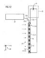
- FIG. 1 shows a side view of a measuring element 1a, 1b, 1c, 2, 3 or 31 of the flow measuring device according to the invention with a plug-in connection 15 attached to one end of the measuring element 1a, 1b, 1c, 2, 3 or 31 for connecting the measuring element 1a, 1b, 1c, 2, 3 or 31 to a control unit 20 and an evaluation unit 23 (see FIG FIGS. 8 to 12 and FIG. 14 ).
- the measuring element 1a, 1b, 1c, 2, 3 or 31 is rod-shaped.
- the measuring element 1a, 1b, 1c, 2, 3 or 31 can be made elastic, so that the geometric shape can be adapted to the given requirements.
- a coordinate system 80 is associated with an x, y and z axis for a better overview.
- the fluid 22 flowing in the x direction is indicated by arrows pointing in the x direction.
- the fluid flow is in particular a turbulent flow. Different flow velocities are set on the surface 9 of the measuring element 1a, 1b, 1c, 2, 3 or 31.
- the length of the arrows indicates the amount of fluid velocity at the location shown.
- the velocities are highest at that part of the measuring element surface 9 which is directed substantially in the direction of flow, it is lowest at that part of the measuring element surface 9 which points substantially in the flow direction.
- the heat transfer through the measuring element surface 9 takes place inhomogeneous depending on the local flow velocity.
- the heat transfer at that part of the measuring element surface 9, which is directed substantially opposite to the flow direction greater than at that part of the measuring element surface 9, which has substantially in the flow direction.
- the at least one heating element 5, 6 or 7 for example, in the center of the cross-sectional area of the measuring element 1a, 1b, 1c, 2, 3 or 31, at least with respect of its cross section in a thermal equilibrium, while it is acted upon by means of the at least one heating element 5, 6 or 7 with heat, an optical waveguide 4a arranged at or closer to that part of the measuring element surface 9, which is directed substantially in the direction of flow, becomes a lower one Have temperature, as an at or closer to that part of the measuring element surface 9, which faces substantially in the flow direction, arranged optical waveguide 4b.
- the optical waveguide 4a arranged at or closer to that part of the measuring element surface 9 which is directed essentially in the direction of flow is exposed to a lower heat flow 10a from the direction of the at least one heating element 5, 6 or 7 than at or closer to that part of the measuring element surface 9, which points substantially in the flow direction, arranged optical waveguide 4b.
- the heat flow associated with this optical waveguide 4b is indicated by 10b.
- the arrows pointing from the at least one heating element 5, 6 or 7 in the direction of the respective optical waveguides 4a, 4b indicate the corresponding heat flow 10a, 10b, the amount of which is reflected in the respective arrow length.
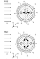
- FIG. 2, FIG. 3 and FIG. 4 show three embodiments of a measuring element 1a, 1b and 1c of the flow measuring device according to the invention.
- FIG. 2 are two optical waveguides 4a, 4b and an interposed heating element 5 embedded in a ceramic material in the measuring element 1a included.
- FIG. 3 are two optical waveguides 4a, 4b and two interposed heating elements 5 embedded in the ceramic material in the measuring element 1b.
- an optical waveguide 4a is arranged close to that part of the measuring element surface 9 which is directed substantially in the direction of flow, while the other optical waveguide 4b is positioned close to that part of the measuring element surface 9 which is directed substantially in the flow direction.
- the one Heating element 5 in FIG. 2 and both heating elements 5 in FIG. 3 are on an axis of symmetry 30 of the measuring element 1a and 1b, which simultaneously represents the mirror axis with respect to both optical fibers 4a, 4b, arranged such that their respective distances to the two optical fibers 4a, 4b correspond to each other.
- the embodiment in FIG. 4 are four optical waveguides 4a, 4b and an interposed heating elements 5 embedded in the ceramic material contained in the measuring element 1c.
- the four optical waveguides 4a, 4b are arranged in pairs near that part of the measuring element surface 9 which is directed substantially in the direction of flow or near that part of the measuring element surface 9 which is directed substantially in the direction of flow.
- the heating element 5 is arranged on an axis of symmetry 30 of the measuring element 1c, which simultaneously represents the mirror axis with respect to the optical waveguide pairs 4a, 4b, such that their distances from the respective optical waveguides 4a, 4b correspond to one another.
- the optical waveguides 4a, 4b are for example glass or plastic fibers.
- the at least one heating element 5 and the optical waveguides 4a, 4b are embedded in a ceramic body, in particular a cylindrical body 16, which in turn is surrounded by a passivating jacket 8.
- the one (cf. Figures 2 and 4 ) or the two (cf. FIG. 3 ) Heating elements 5 are formed for example as heating wires.
- the sheath 8 can also be designed to be electrically conductive from a metal (cf. FIGS. 8 and 10 ).
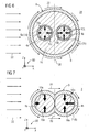
- FIG. 5 shows a further embodiment of a measuring element 2 of the flow measuring device according to the invention with two optical waveguides 4a and 4b, which are surrounded by a ceramic material consisting in particular cylindrical body 16.
- An optical waveguide 4a is arranged close to that part of the measuring element surface 9 which is directed substantially in the direction of flow, while the other optical waveguide 4b is located close to that part of the measuring element surface 9 which is essentially in the flow direction is directed, is positioned.
- a heating element 6 is arranged such that it surrounds the measuring element 2. In particular, the heating element 6 simultaneously forms a sleeve-shaped casing 8 of the measuring element 2.
- FIG. 6 FIG. 2 illustrates another embodiment of a measuring element 31 of the flow measuring device according to the invention with two optical waveguides 4a and 4b.
- Each optical waveguide 4a, 4b is surrounded by a corresponding heating element 6a, 6b or 7a, 7b in the form of a sleeve 6a, 6b or a coating 7a, 7b.
- the heating elements 6a, 6b or 7a, 7b are in turn surrounded by a ceramic material consisting in particular cylindrical body 16.
- An optical waveguide 4a with associated heating element 6a or 7a are arranged close to that part of the measuring element surface 9 which is directed substantially in the direction of flow, while the other optical waveguide 4b with associated heating element 6b or 7b near that part of the measuring element surface 9, which is substantially in Direction of flow is directed, are positioned.
- the ceramic body 16 itself is in turn surrounded by a sleeve-shaped passivating jacket 8 of the measuring element 31.
- FIG. 7 is a section through a measuring element 3 of the flow measuring device according to the invention, wherein two adjacent optical fibers 4a, 4b are vapor-deposited with a metal layers 7a, 7b, which also represents a heating element 7 of the measuring element 3.
- the metal layer 7 forms a common jacket 8 of the optical fibers 4a, 4b.
- This embodiment is characterized by an elasticity, so that the measuring element 3 can be adjusted as needed in its spatial extent.
- the measuring element 3 is distinguished by a particularly simple production method, in which the optical waveguide pair 4a, 4b is coated in a coating process of a conventional, known type with a suitable electrically conductive material.
- the embodiment is characterized further by from that they have a particularly low heat capacity compared to the embodiments of the measuring element 1a, 1b, 1c, 2 or 31 according to the FIGS. 1 to 6 and thus reacts faster to changing flow conditions.
- the heating elements 5, 6 and 7 used in the aforementioned embodiments are preferably formed of a metal or of a metal alloy.
- a metal alloy for example steel, copper, aluminum, bronze, constantan or the like can be used.
- a coating with a metal for example in the flow channel of a gas turbine, a coating with a metal such as tungsten or the like is preferable.
- conductive polymers can be used.
- the material of the heating elements 5, 6 and 7 each have a constant electrical resistance. In particular, the resistance in the operating temperature range is largely independent of the temperature.
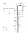
- FIGS. 8 to 12 show exemplary embodiments of the flow measuring device according to the invention in block diagrams.
- the flow measuring device in FIG. 8 comprises the measuring element 1a according to FIG. 2
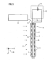
- the flow measuring device in FIG. 9 comprises the measuring element 1b according to FIG. 3
- the flow measuring device in FIG. 10 includes the measuring element 1c according to FIG. 4
- the flow measuring device in FIG. 11 includes the measuring element 31 according to FIG. 6
- the flow measuring device in FIG. 12 includes the measuring element 2 or 3 according to FIG. 5 respectively.
- FIG. 7 All mentioned embodiments the flow measuring device according to the invention further comprise a control unit 20 and an evaluation unit 23.
- the respective measuring element 1a, 1b, 1c, 2, 3 or 31 extends in its longitudinal axis in the y-direction.
- the measuring element 2 or 3 of the flow measuring device according to the FIG. 12 is at its respective ends with its heating element 6 or 7 electrically connected to the control unit 20 and at one of the two ends optically connected to the evaluation unit 23.
- the two optical waveguides 4a and 4b are connected in common to the evaluation unit 23 via a respective optical connecting fiber 25a, 25b.
- the measuring element 1a, 1b, 1c or 31 of the flow measuring device according to the FIGS. 8 to 11 is electrically connected at one end to the control unit 20 and optically connected to the evaluation unit 23, while the other end of the measuring element 1 is freely available.
- One of the optical waveguides 4a, 4b of the measuring element 1a, 1b, 1c or 31 is connected via an optical connecting fiber 25 to the evaluation unit 23, wherein the optical waveguides 4a, 4b are interconnected in series.
- the individual optical fibers 4a, 4b can also be analogous to FIG. 12 be individually connected to the evaluation unit 23 without having to connect to each other.
- the control unit 20 has an electrical energy source 21.
- the power source 21 having two terminals is connected to the heating elements 5, 6 or 7 according to the embodiments such that the heating element 5, 6 or 7 is supplied with electric power and generates heat.
- the electrical energy source 21 is in particular a current source, via which a constant direct current can be predetermined.
- the measuring element 1a, 1b, 1c, 2, 3 or 31 flows around the fluid 22, wherein the fluid flow along the longitudinal extension of the measuring element 1a, 1b, 1c, 2, 3 or 31 may have a different flow velocity indicated through the arrows of different lengths.
- the flow direction of the fluid 22 has, for simplicity, in the x-direction, as already stated above.
- the heating element 5, 6 or 7 of the measuring element 1a, 1b, 1c, 2, 3 and 31 is supplied with electrical power, so that this heats up.
- the heating process should last at least until a thermal equilibrium has been established in the measuring element 1a, 1b, 1c, 2, 3 or 31. He can also be chosen shorter.
- the evaluation unit 23 which has a light source, a detector and an analyzing means
- light in the form of a continuous laser beam or in the form of laser pulses, is transmitted via the optical connecting fiber 25 into the optical waveguides 4a, 4b of the measuring element 1a, 1b, 1c, 2 , 3 or 31 coupled and analyzed backscattered light with the analysis means.
- the effect is exploited that an electromagnetic wave, which is coupled into an optical waveguide 4a, 4b, is scattered when passing through the optical waveguide 4a, 4b. A part of the scattered light is scattered in the opposite direction, so that it can be detected at the entrance of the optical waveguide 4a, 4b.
- the backscattered light signal consists of different components that are different in terms of measurement requirements.
- the backscattered signal contains a Raman scattered portion.
- the laser light is generated in known manner with prior art devices. Depending on the temperature, part of the laser light in the optical waveguides 4a, 4b is scattered back by fiber Bragg gratings 13. This backscattered Light signal is supplied via the optical connecting fiber 25 of the evaluation unit 23, which determines therefrom the temperature at the location of the fiber Bragg gratings 13 in the optical waveguide 4.
- the corresponding individual optical waveguides 4a, 4b associated temperatures within the measuring element 1a, 1b, 1c, 2, 3 or 31 are determined.
- different temperatures occur at the location of the optical waveguides 4a, 4b in the measuring element 1, 2 or 3 in a flowing fluid 22 with directed flow.
- the different temperatures are compared with each other, for example by subtraction in one of the evaluation unit 23 associated computer unit, and from which determines the flow direction of the fluid 22.
- the flow velocity with the flow velocity distribution of the fluid 22 can be determined from the temperature distribution along the measuring element 1a, 1b, 1c, 2, 3 or 31.
- the measuring element 1a has a heating element 5 designed, for example, as a heating wire.
- the energy source 21 is connected to the heating element 5 by one connection and to the electrically conductive jacket 8 of the measuring element 1a by the other connection.
- the heating element 5 is also connected to the electrically conductive sheath 8 at the opposite end of the measuring element 1a.
- the measuring element 1b has two parallel For example, designed as heating wires heating elements 5, wherein the two heating wires are connected together at one end of the measuring element 1b with an electrical connection conductor. At the other end of the measuring element 1b while one of the two heating elements 5 are connected to one terminal of the power source 21 and the other heating element 5 to the other terminal of the power source 21. Likewise, at one end of the measuring element 1 b, the two parallel optical waveguides 4 a, 4 b are interconnected with an optical connecting fiber, while at the other end measuring element 1 b only one of the two optical waveguides 4 a, 4 b is connected to the evaluation unit 23 via an optical connecting fiber 25.
- the measuring element 1 has a total of four parallel optical waveguides 4a, 4b. Between the optical waveguides designed as a heating wire heating elements 5 is arranged.
- the energy source 21 is connected to the heating element 5 with one connection and to the electrically conductive jacket 8 of the measuring element 1c via the other connection.
- the heating element 5 is also connected to the electrically conductive sheath 8 at the opposite end of the measuring element 1c.
- the four optical waveguides 4a, 4b are connected to one another in series by means of optical connecting fibers at the measuring element ends, so that only one of the optical waveguides 4a, 4b is connected directly to the evaluation unit 23.
- measuring element 1c with numerous optical waveguides 4a, 4b, which are arranged, for example, in a circle around the heating element 5 arranged in the cross-sectional center of the measuring element 1c, allows an even more accurate determination of the flow direction of the fluid 22.
- the measuring element 31 has two parallel heating elements 5 formed, for example, as electrically conductive sleeves or coatings, the two on one end of the measuring element 31 are joined together. At the other end of the measuring element 31 while one of the two heating elements 5 are connected to one terminal of the power source 21 and the other heating element 5 to the other terminal of the power source 21. Likewise, at one end of the measuring element 1 b, the two parallel optical waveguides 4 a, 4 b are interconnected with an optical connecting fiber, while at the other end measuring element 1 b only one of the two optical waveguides 4 a, 4 b is connected to the evaluation unit 23 via an optical connecting fiber 25.
- both heating elements 5 must be connectable together with one and the same connection of the energy source 21.
- FIG. 12 is a connection of the power source 21 at one end of the measuring element 2 or 3 with the electrically conductive sleeve 8 (FIG. FIG. 5 ) or as an electrically conductive coating ( FIG. 7 ) formed heating element 6 or 7 connected.
- the second terminal of the power source 21 is connected at the other end of the measuring element 2 or 3 by means of an electrical line to the heating element 6 or 7.
- FIG. 9 shows a circular cross section of a flow channel 14 through which a fluid 22 flows in the x direction.
- the flow channel 14 is provided as an example with two with respect to the flow channel cross-section radially arranged measuring elements 1a, 1b, 1c, 2, 3 or 31.
- the two measuring elements 1a, 1b, 1c, 2, 3 or 31 are connected via an electrical connection line 26 with the control unit 20 and an optical connection fiber 25 is connected to the evaluation unit 23.
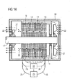
- a generator is shown schematically as an electrical machine.
- the generator has a stationary stator 19 fixedly connected to a housing 28 and a rotor 18 movably mounted on a rotor shaft 17.
- the generator is cooled by means of a cooling device with, for example, air as cooling fluid 22.
- the cooling device has two fans 27, which conduct the cooling air 22 through the generator by means of a line system.
- the line system has numerous flow channels, in particular also in the stator 19.
- the cooling air 22 is conducted in the illustrated embodiment from outside to inside in the direction of rotor 18 through the stator 19 and further transported by a gap between stator 19 and rotor 18 gap to the outside.
- the flow direction in the flow channels is monitored by means of the flow measuring device according to the invention.
- two flow channels, each with a measuring element 1a, 1b, 1c, 2, 3 or 31 of the flow measuring device according to the invention are provided as an example at two points of the generator. Both measuring elements 1a, 1b, 1c, 2, 3 or 31 are connected to the associated control unit 20 and evaluation unit 23. In the case of irregularities in the flow of cooling air, it is therefore possible to react promptly and to take appropriate protective measures.
- cooling fluid 22 may also be a cooling liquid, such as water or even in cryogenic cooling, a liquid noble gas or liquid nitrogen may be provided.
- the flow measuring device according to the invention can also be used in a turbine, such as a steam turbine or a gas turbine.
- a turbine such as a steam turbine or a gas turbine.
- flow directions can be measured, in particular in turbulent flow regions in the associated cooling air system, in the associated compressor, at the associated compressor inlet and / or in the corresponding exhaust gas flow.
Landscapes
- Physics & Mathematics (AREA)
- General Physics & Mathematics (AREA)
- Fluid Mechanics (AREA)
- Engineering & Computer Science (AREA)
- Aviation & Aerospace Engineering (AREA)
- Indicating Or Recording The Presence, Absence, Or Direction Of Movement (AREA)
- Measuring Volume Flow (AREA)
- Investigating Or Analysing Materials By Optical Means (AREA)
Description
Die vorliegende Erfindung betrifft ein Strömungsmessvorrichtung zur Bestimmung einer Strömungsrichtung eines Fluids. Die Strömungsmessvorrichtung weist dabei ein Messelement mit mindestens zwei Lichtwellenleitern und mindestens einem zu den Lichtwellenleitern benachbart angeordneten elektrischen Heizelement, eine Steuerungseinheit und eine Auswerteeinheit auf. Ferner betrifft die Erfindung ein Verfahren zum Bestimmen einer Strömungsrichtung eines Fluids sowie eine elektrische Maschine mit der Strömungsmessvorrichtung.The present invention relates to a flow measuring device for determining a flow direction of a fluid. The flow measuring device in this case has a measuring element with at least two optical waveguides and at least one adjacent to the optical waveguides electrical heating element, a control unit and an evaluation unit. Furthermore, the invention relates to a method for determining a flow direction of a fluid and to an electrical machine with the flow measuring device.
In elektrischen Maschinen aller Leistungsklassen, insbesondere aber mit höherer Leistung, wird eine erhebliche Wärme entwickelt, die im Hinblick auf eine verbesserte Maschineneffizienz und/oder höherer Lebensdauer mittels kühltechnischer Maßnahmen abzuführen ist. So sind beispielsweise luftgekühlte Maschinen wie Generatoren oder Motoren, insbesondere mit Leistungen unter 300 MVA, bekannt, bei denen eine Kühlung durch einen vergleichsweise großen Luftstrom erfolgt. Dieser Luftstrom kann insbesondere durch ein zahlreiche Strömungskanäle umfassendes Leitungssystem geleitet werden (vgl. z.B. die
Aus dem Dokument
Aus der
In der
Der vorliegenden Erfindung liegt daher die Aufgabe zugrunde, eine Strömungsmessvorrichtung sowie ein Verfahren bereitzustellen, mit welchen die Strömungsrichtung eines Fluids ermittelbar ist, als auch eine elektrische Maschine anzugeben, bei welcher die Strömungsrichtung eines Kühlfluids überwacht werden kann.The present invention is therefore based on the object to provide a flow measuring device and a method with which the flow direction of a fluid can be determined, and to provide an electrical machine in which the flow direction of a cooling fluid can be monitored.
Zur Lösung der Aufgabe wird eine Strömungsmessvorrichtung entsprechend den Merkmalen des unabhängigen Patentanspruchs 1 angegeben.To achieve the object, a flow measuring device according to the features of independent claim 1 is given.
Bei der erfindungsgemäßen Strömungsmessvorrichtung handelt es sich um eine Strömungsmessvorrichtung zur Bestimmung einer Strömungsrichtung eines Fluids, aufweisend
- ein von dem Fluid umströmbares Messelement mit mindestens zwei Lichtwellenleitern und mindestens einem zu den Lichtwellenleitern benachbart angeordneten elektrischen Heizelement, wobei
- die Lichtwellenleiter über jeweils einen vom mindestens einen Heizelementen zu den jeweiligen Lichtwellenleitern gerichteten Wärmestrom mit Wärme beaufschlagbar ist,
- die Richtungen der Wärmeströme zumindest anteilig entgegengesetzt sind,
- die einzelnen Wärmeströme unterschiedlich stark mit der Strömungsrichtung des Fluids korreliert sind, und
- wenigstens eine in die Lichtwellenleiter einkoppelbare elektromagnetische Welle entsprechend der jeweiligen Temperatur der Lichtwellenleiter beeinflussbar ist,
- eine Steuerungseinheit, mit welcher dem zumindest einen Heizelement elektrischen Leistung zuführbar ist, und
- eine Auswerteeinheit, mit welcher die von den einzelnen Wärmeströmen ausgehende Temperaturbeeinflussung der mindestens einen elektromagnetischen Welle auswertbar und die Strömungsrichtung des Fluids bestimmbar ist.
- one of the fluid flow around the measuring element with at least two optical waveguides and at least one adjacent to the optical waveguides electrical heating element, wherein
- the optical waveguides can be acted upon by heat in each case via a heat flow directed by the at least one heating elements to the respective optical waveguides,
- the directions of the heat flows are at least partially opposite,
- the individual heat flows are correlated to different degrees with the flow direction of the fluid, and
- at least one can be coupled into the optical waveguide electromagnetic wave corresponding to the respective temperature of the optical waveguide can be influenced,
- a control unit with which the at least one heating element electrical power is supplied, and
- an evaluation unit with which the temperature influence of the at least one electromagnetic wave emanating from the individual heat flows can be evaluated and the flow direction of the fluid can be determined.
Das Messelement, das in seine Längserstreckung vorzugsweise senkrecht zur Strömungsrichtung des Fluids in diesem angeordnet ist, weist über den Umfang seines Querschnittes, welcher insbesondere kreisförmig ist, unterschiedliche örtliche Strömungsverhältnisse auf. So erfolgt der Wärmetransport über die Oberfläche des Messelements aufgrund der örtlich unterschiedlichen Strömungsgeschwindigkeiten des Fluids nicht gleichmäβig über den Umfang des Querschnitts. Im Messelement stellt sich aus diesem Grunde bei konstanter Leistungsbeaufschlagung des mindestens einen Heizelements betragsmäßig jeweils ein unterschiedlicher Wärmestrom in Richtung der Lichtwellenleiter ein, welche abhängig von der Position der Lichtwellenleiter im Messelement sind. Abhängig von der Anordnung der Lichtwellenleiter relativ zur Strömungsrichtung können sich somit am jeweiligen Ort der Lichtwellenleiter unterschiedliche Temperaturen einstellen. Aus der Bestimmung der entsprechenden Temperaturunterschiede kann schließlich auf die Strömungsrichtung des das Messelement umströmenden Fluids geschlossen werden.The measuring element, which is arranged in its longitudinal extent preferably perpendicular to the flow direction of the fluid in this, has over the circumference of its cross-section, which is in particular circular, different local flow conditions. Thus, the heat transfer across the surface of the measuring element does not take place uniformly over the circumference of the cross section due to the spatially different flow velocities of the fluid. For this reason, a different heat flow in the direction of the optical waveguides, which are dependent on the position of the optical waveguides in the measuring element, is established in the measuring element for constant application of power to the at least one heating element. Depending on the arrangement of the optical waveguides relative to the flow direction, different temperatures can thus be set at the respective location of the optical waveguide. From the determination of the corresponding temperature differences, it is finally possible to deduce the flow direction of the fluid flowing around the measuring element.
Vorteilhafte Ausgestaltungen der Strömungsmessvorrichtung gemäß der Erfindung ergeben sich aus den von Anspruch 1 abhängigen Ansprüchen.Advantageous embodiments of the flow measuring device according to the invention will become apparent from the dependent claims of claim 1.
So ist es günstig, wenn die Lichtwellenleiter jeweils zumindest ein Faser-Bragg-Gitter umfassen und die wenigstens eine in die Lichtwellenleiter einkoppelbare elektromagnetische Welle entsprechend der jeweiligen Temperatur der Lichtwellenleiter am Ort der mindestens zwei Faser-Bragg-Gitters beeinflussbar ist. Ein solcher Sensortyp zeichnet sich durch seine besondere Multiplexfähigkeit aus, so dass auf einfache Weise ein Sensornetzwerk realisiert werden kann. Ein weiterer Vorteil der Faser-Bragg-Gitter-Technologie ist die Möglichkeit einer praktisch punktförmigen, also einer lokal sehr eng begrenzten Messung. Damit ist es möglich, bei Notwendigkeit einer höheren, insbesondere ortsaufgelösten Messgenauigkeit entlang des Messelements mehrere Faser-Bragg-Gitter nahe beieinander in den jeweiligen Lichtwellenleitern nacheinander anzuordnen.Thus, it is favorable if the optical waveguides each comprise at least one fiber Bragg grating and the at least one electromagnetic wave which can be coupled into the optical waveguides can be influenced at the location of the at least two fiber Bragg gratings in accordance with the respective temperature of the optical waveguides. Such a sensor type is characterized by its special multiplexing capability, so that a sensor network can be realized in a simple manner. Another advantage of the fiber Bragg grating technology is the possibility of a practically punctiform, so a locally very narrow measurement. This makes it possible, if a higher, in particular spatially resolved measurement accuracy along the measuring element is required, to arrange a plurality of fiber Bragg gratings close to one another in the respective optical waveguides one after the other.
Zur besseren Unterscheidbarkeit haben die in einem Lichtwellenleiter angeordneten Faser-Bragg-Gitter vorzugsweise jeweils eine voneinander verschiedene Schwerpunktwellenlänge. In jedem Faser-Bragg-Gitter wird von der mindestens einen eingespeisten elektromagnetischen Welle ein durch die jeweilige Schwerpunktswellenlänge bestimmter Anteil zurückreflektiert. Die Schwerpunktswellenlänge ändert sich mit der am Messort herrschenden Einflussgröße, hier insbesondere der Temperatur des Lichtwellenleiters. Diese Veränderung im Wellenlängengehalt (oder Wellenlängenspektrum) des jeweiligen zurückreflektierten Teils der eingespeisten mindestens einen elektromagnetischen Welle wird als Maß für die zu erfassende Einflussgröße verwendet werden. Es ist prinzipiell aber auch möglich, den transmittierten Teil der eingespeisten mindestens einen elektromagnetischen Welle auf die Veränderung im Wellenlängenspektrum zu untersuchen. Zur Abfrage der Faser-Bragg-Gitter mittels der mindestens einen elektromagnetischen Welle kann insbesondere eine breitbandige Lichtquelle, wie beispielsweise eine LED (Leuchtdiode, engl.: Light Emitting Diode) mit einer Bandbreite von etwa 45 nm, eine SLD (Superlumineszenzdiode, engl.: Super Luminescence Diode) mit einer Bandbreite von etwa 20 nm oder ein durchstimmbarer Laser mit einer Bandbreite von etwa 100 nm, zum Einsatz kommen.For better distinctness, the fiber Bragg gratings arranged in an optical waveguide preferably each have a different centroid wavelength. In each fiber Bragg grating, a portion determined by the respective center of gravity wavelength is reflected back by the at least one fed-in electromagnetic wave. The center of gravity wavelength changes with the influencing variable prevailing at the measuring location, here in particular the temperature of the optical waveguide. This change in the wavelength content (or wavelength spectrum) of the respective back-reflected part of the fed-in at least one electromagnetic wave will be used as a measure of the influencing variable to be detected. In principle, however, it is also possible to examine the transmitted part of the fed-in at least one electromagnetic wave for the change in the wavelength spectrum. To query the fiber Bragg gratings by means of the at least one electromagnetic wave, in particular a broadband light source, such as For example, an LED (light-emitting diode, engl .: L ight E mitting D iode) with a bandwidth of about 45 nm, an SLD (super luminescent diode, engl .: S uper L uminescence D iode) with a bandwidth of about 20 nm or a tunable laser with a bandwidth of about 100 nm, are used.
Es wird vorgeschlagen, dass das Messelement stabförmig ausgebildet ist. Vorteilhaft ist das Messelement einfach zu montieren und kann beispielsweise durch eine Öffnung in den Strömungskanal eingeführt werden. Ferner kann erreicht werden, dass mit geringem Montageaufwand eine Wartung des Messelements ermöglicht wird. Dazu werden die entsprechenden Befestigungen gelöst und das Messelement durch die Öffnung herausgezogen. Daneben kann das Messelement natürlich jede beliebige andere Form aufweisen. Beispielsweise kann das Messelement kreisförmig oder auch als archimedische Spirale ausgebildet seinIt is proposed that the measuring element is rod-shaped. Advantageously, the measuring element is easy to assemble and can be introduced, for example, through an opening in the flow channel. Furthermore, it can be achieved that a maintenance of the measuring element is made possible with low assembly costs. For this purpose, the corresponding fasteners are released and the measuring element pulled out through the opening. In addition, the measuring element can of course have any other shape. For example, the measuring element may be circular or designed as an Archimedean spiral
In einer weiteren Ausgestaltung wird vorgeschlagen, dass das Messelement elastisch ist. So kann vorteilhaft das Messelement je nach Einsatz kurzfristig vorgeformt werden, wodurch die Anzahl der verschiedenen Messelementformen reduziert werden kann. Kosten für Lagerhaltung können eingespart werden.In a further embodiment, it is proposed that the measuring element is elastic. Thus, advantageously, the measuring element can be preformed at short notice depending on the application, whereby the number of different measuring element shapes can be reduced. Storage costs can be saved.
Es ist günstig, wenn das mindestens eine Heizelement aus Metall gebildet ist. Somit ist eine gleichmäßige Erwärmung längs der Heizelemente gewährleistet.It is favorable if the at least one heating element is formed from metal. Thus, a uniform heating along the heating elements is ensured.
Weiterhin wird vorgeschlagen, dass das mindestens eine Heizelement durch eine gemeinsame elektrisch leitfähige Beschichtung der Lichtwellenleiter gebildet ist, wobei die Lichtwellenleiter in Längsrichtung in Kontakt sind. So kann die Bauform des Messelements weiter vereinfacht werden. Das Heizelement kann so auf einfache Weise jeweils einstückig mit den miteinander in Kontakt stehenden Leitern verbunden sein, so dass neben einer kostengünstigen Herstellung auch eine Schutzfunktion der Leiter durch die Heizelemente erreicht werden kann. Die leitfähige Beschichtung kann beispielsweise aus einem Metall wie Wolfram oder auch aus einer Legierung wie beispielsweise Stahl oder dergleichen gebildet sein.Furthermore, it is proposed that the at least one heating element is formed by a common electrically conductive coating of the optical waveguides, wherein the optical waveguides are in contact in the longitudinal direction. Thus, the design of the measuring element can be further simplified. The heating element can thus be connected in a simple manner in each case in one piece with the conductors which are in contact with one another, so that in addition to a cost-effective production, a protective function of the conductors can also be achieved by the heating elements. The conductive coating may be, for example be formed of a metal such as tungsten or of an alloy such as steel or the like.
Es wird ferner vorgeschlagen, dass das mindestens eine Heizelement einen konstanten spezifischen elektrischen Widerstand aufweist. So kann vorteilhaft erreicht werden, dass das Messelement über seine Längserstreckung gleichmäßig mit Wärme beaufschlagt wird. Unter spezifischem elektrischem Widerstand ist im Rahmen dieser Anmeldung der elektrische Widerstand pro Längeneinheit zu verstehen.It is further proposed that the at least one heating element has a constant specific electrical resistance. Thus, it can advantageously be achieved that the measuring element is uniformly exposed to heat over its longitudinal extent. Specific electrical resistance in the context of this application is to be understood as the electrical resistance per unit length.
Darüber hinaus wird vorgeschlagen, dass der spezifische Widerstand im Betriebstemperaturbereich weitgehend temperaturunabhängig ist. So kann erreicht werden, dass die jeweilige vom mindestens einen Heizelement in Richtung der Lichtwellenleiter gerichtete Wärmezufuhr entlang der Längserstreckung des Messelements im Wesentlichen unabhängig von der aktuellen lokalen Temperatur ist. Die Messgenauigkeit sowie auch die Zuverlässigkeit der Messung kann erhöht werden. Dazu kann das mindestens eine Heizelement beispielsweise aus einem Werkstoff wie Konstantan oder dergleichen gebildet sein.In addition, it is proposed that the specific resistance in the operating temperature range is largely independent of temperature. It can thus be achieved that the respective heat supply directed by the at least one heating element in the direction of the optical waveguide is substantially independent of the current local temperature along the longitudinal extent of the measuring element. The measurement accuracy as well as the reliability of the measurement can be increased. For this purpose, the at least one heating element may be formed, for example, from a material such as constantan or the like.
In einer vorteilhaften Weiterbildung wird vorgeschlagen, dass das Messelement eine Ummantelung aufweist. Das Messelement kann so beispielsweise gegen eine chemische Beanspruchung geschützt werden. Darüber hinaus ermöglicht die Ummantelung einen mechanischen Schutz, beispielsweise während der Montage.In an advantageous development, it is proposed that the measuring element has a casing. The measuring element can thus be protected against chemical attack, for example. In addition, the sheath allows mechanical protection, for example during assembly.
Es wird ferner vorgeschlagen, dass die Ummantelung aus einem keramischen Werkstoff besteht. Mit der keramischen Ummantelung kann vorteilhaft ein Messelement für eine hohe Temperaturbeanspruchung gebildet werden.It is further proposed that the sheath consists of a ceramic material. With the ceramic jacket can advantageously be formed a measuring element for a high temperature stress.
Daneben wird vorgeschlagen, dass die Ummantelung durch eine Metallhülse gebildet ist. So kann vorteilhaft das Messelement beispielsweise gegen eine elektrostatische Aufladung geschützt werden, indem die Metallhülse mit einem Erdpotential verbindbar ist.In addition, it is proposed that the sheath is formed by a metal sleeve. Thus, advantageously, the measuring element can be protected, for example against electrostatic charge by the metal sleeve is connected to a ground potential.
Darüber hinaus wird vorgeschlagen, dass die Ummantelung (8) zugleich das mindestens eine Heizelement (6, 7) aufweist. Bauteile und Kosten können weiter reduziert werden.In addition, it is proposed that the sheath (8) at the same time having at least one heating element (6, 7). Components and costs can be further reduced.
Zur weiteren Lösung der Aufgabe wird ein Verfahren entsprechend den Merkmalen des unabhängigen Anspruchs 12 angegeben.To further achieve the object, a method according to the features of
Bei dem erfindungsgemäßen Verfahren handelt es sich um ein Verfahren zum Bestimmen einer Strömungsrichtung eines Fluids mit einer Strömungsmessvorrichtung, wobei
- mindestens eine elektromagnetische Welle in mindestens zwei Lichtwellenleiter eines vom Fluid umströmten Messelements eingekoppelt wird,
- zumindest einem Heizelement des Messelements derart elektrischen Leistung zugeführt wird, dass
- die Lichtwellenleiter von den Heizelementen mit Wärme beaufschlagt und
- die mindestens eine elektromagnetische Welle in Abhängigkeit von der unterschiedlichen lokalen Temperatur in den zumindest zwei Lichtwellenleitern unterschiedlich stark beeinflusst wird,
- die unterschiedlichen Beeinflussungen der mindestens einen elektromagnetischen Welle ermittelt und daraus die Strömungsrichtung des Fluids senkrecht zur Längserstreckung des Messelements bestimmt wird.
- at least one electromagnetic wave is coupled into at least two optical waveguides of a measuring element surrounded by the fluid,
- at least one heating element of the measuring element is supplied in such an electric power that
- the optical fibers from the heating elements with heat and
- the at least one electromagnetic wave is influenced differently depending on the different local temperature in the at least two optical waveguides,
- determines the different influences of the at least one electromagnetic wave and from this the flow direction of the fluid is determined perpendicular to the longitudinal extent of the measuring element.
Bei dem erfindungsgemäßen Verfahren ergeben sich die vorstehend für die erfindungsgemäße Strömungsmessvorrichtung erläuterten Vorteile.In the method according to the invention, the advantages explained above for the flow measuring device according to the invention result.
So ist es auch günstig, wenn die Lichtwellenleiter jeweils mindestens ein Faser-Bragg-Gitter umfassen und die mindestens eine elektromagnetische Welle in Abhängigkeit von den unterschiedlichen, lokalen Temperaturen am Ort des jeweiligen mindestens einen Faser-Bragg-Gitters beeinflusst wird.Thus, it is also advantageous if the optical waveguides each comprise at least one fiber Bragg grating and the at least one electromagnetic wave is influenced as a function of the different, local temperatures at the location of the respective at least one fiber Bragg grating.
Darüber hinaus wird vorgeschlagen, dass die mindestens eine elektromagnetische Welle durch mindestens einen elektromagnetischen Impuls gebildet ist. Vorteilhaft kann Energie eingespart sowie die Messgenauigkeit erhöht werden. Der elektromagnetische Impuls kann beispielsweise durch einen gepulsten Laser erzeugt werden, der über geeignete bekannte Kopplungsmittel in die Lichtwellenleiter eingekoppelt wird.In addition, it is proposed that the at least one electromagnetic wave is formed by at least one electromagnetic pulse. Advantageously, energy can be saved and the measurement accuracy can be increased. The electromagnetic pulse can be generated for example by a pulsed laser, which is coupled via suitable known coupling means in the optical waveguide.
Ferner wird vorgeschlagen, dass das Messelement in seiner Längserstreckung durch das mindestens eine Heizelement erwärmt wird. Aus einer Temperaturvariation längs des Messelementes aufgrund der Fluidströmung kann vorteilhaft auch die Strömungsgeschwindigkeit entlang des Messelementes ermittelt werden.It is also proposed that the measuring element is heated in its longitudinal extent by the at least one heating element. From a temperature variation along the measuring element due to the fluid flow can advantageously be determined, the flow velocity along the measuring element.
Vorteilhaft ist, dass das mindestens eine Heizelement mit einer konstanten elektrischen Leistung beaufschlagt wird. Insbesondere bei einem über die Längserstreckung des Messelements konstanten Widerstandsverlauf kann somit gemäß dem ohmschen Gesetz jeweils eine konstante Wärmebeaufschlagung erreicht werden. Dies kann mittels Gleichstrom oder auch Wechselstrom erfolgen. Insbesondere kann durch Variation der Wechselstromfrequenz die Heizwirkung des mindestens einen Heizelements beeinflusst werden, wenn sich die Frequenz in einen Bereich bewegt, in dem Stromverdrängungseffekte wirksam werden.It is advantageous that the at least one heating element is acted upon by a constant electrical power. In particular, in the case of a resistance course which is constant over the longitudinal extension of the measuring element, a constant application of heat can thus be achieved in each case in accordance with Ohm's law. This can be done by means of direct current or alternating current. In particular, by varying the AC frequency, the heating effect of the at least one heating element can be influenced when the frequency moves within a range in which current displacement effects take effect.
In einer vorteilhaften Weiterbildung des erfindungsgemäßen Verfahrens wird vorgeschlagen, dass mehrere Messungen mit unterschiedlicher Leistungsbeaufschlagung durchgeführt werden. So kann die Messgenauigkeit weiter erhöht werden.In an advantageous development of the method according to the invention, it is proposed that a plurality of measurements be carried out with different power application. Thus, the measurement accuracy can be further increased.
Weiterhin wird vorgeschlagen, dass als Fluid ein Gas, insbesondere Luft, oder eine Flüssigkeit, insbesondere Wasser oder flüssiger Stickstoff, zur Kühlung einer elektrischen Maschine, insbesondere eines Generators oder eines Motors, verwendet wird. Das Messelement gemäß der erfindungsgemäßen Strömungsmessvorrichtung kann dabei kostengünstig an die physikalischen und/oder chemischen Anforderungen im Strömungskanal einer Kühleinrichtung des Generators bzw. des Motors angepasst werden. Eine genaue Messung einer Strömungsverteilung im Querschnitt eines Strömungskanals kann zudem ebenfalls erreicht werden.It is also proposed that the fluid used is a gas, in particular air, or a liquid, in particular water or liquid nitrogen, for cooling an electrical machine, in particular a generator or a motor. The measuring element according to the flow measuring device according to the invention can cost to the physical and / or chemical requirements in the flow channel of a cooling device of the generator or of the engine. An accurate measurement of a flow distribution in the cross section of a flow channel can also be achieved.
Ferner wird zur weiteren Lösung der Aufgabe mit der Erfindung eine elektrische Maschine mit
- einem drehbar gelagerten Läufer,
- einem zugeordneten, ortsfesten Stator in einem Maschinengehäuse,
- einer Einrichtung zur Kühlung von Teilen mittels eines Fluids innerhalb des Maschinengehäuses, wobei die Kühleinrichtung ein Leitungssystem enthält, und
- einer erfindungsgemäßen Strömungsmessvorrichtung vorgeschlagen.
- a rotatably mounted runner,
- an associated, fixed stator in a machine housing,
- a device for cooling parts by means of a fluid within the machine housing, wherein the cooling device includes a conduit system, and
- proposed a flow measuring device according to the invention.
Dabei ist ein in einem Strömungskanal des Leitungssystems angeordnetes Messelement der Strömungsmessvorrichtung zur Messung der Strömungsrichtung des Fluids im Strömungskanal vorgesehen.In this case, an arranged in a flow channel of the conduit system measuring element of the flow measuring device for measuring the flow direction of the fluid is provided in the flow channel.
Bei der erfindungsgemäßen elektrischen Maschine ergeben sich die vorstehend für die erfindungsgemäße Strömungsmessvorrichtung erläuterten Vorteile.In the case of the electric machine according to the invention, the advantages explained above for the flow measuring device according to the invention result.
Mit der erfindungsgemäßen Strömungsmessvorrichtung kann eine effiziente Kühlung der Maschine erreicht werden, indem in den Strömungskanälen der Kühleinrichtung die Strömungsrichtung des Kühlfluids, wie beispielsweise Luft, überwacht wird. Ein auftretender Strömungsstillstand durch ungünstig überlagerte Strömungen kann dabei früh genug erkannt werden, so dass geeignete Maßnahmen eingeleitet werden können, um eine örtlichen Überhitzung und Beschädigung der Maschine zu vermeiden. So kann die Zuverlässigkeit eines Betriebs der Strömungsmaschine erhöht werden.With the flow measuring device according to the invention, an efficient cooling of the machine can be achieved by the flow direction of the cooling fluid, such as air, is monitored in the flow channels of the cooling device. An occurring flow arrest due to unfavorably superimposed flows can be detected early enough so that appropriate measures can be taken to prevent local overheating and damage to the machine. Thus, the reliability of an operation of the turbomachine can be increased.
Es wird vorgeschlagen, dass das Messelement radial zum Querschnitt des Strömungskanals angeordnet ist. Vorteilhaft kann dabei mit mehreren nacheinander angeordneten Faser-Bragg-Gittern die Strömungsrichtung in Abhängigkeit des Radius des Strömungskanalquerschnitts ermittelt werden. Selbstverständlich können im Strömungskanal auch mehrere Messelemente vorgesehen sein, um die Strömurigsrichtung an unterschiedlichen Umfangspositionen des Strömungskanals ermitteln zu können.It is proposed that the measuring element is arranged radially to the cross section of the flow channel. Advantageously, the flow direction can be determined as a function of the radius of the flow channel cross section with a plurality of successively arranged fiber Bragg gratings. Of course, a plurality of measuring elements can also be provided in the flow channel in order to be able to determine the direction of flow at different circumferential positions of the flow channel.
Es wird ferner vorgeschlagen, dass im Strömungskanal axial beabstandet mehrere Messelemente angeordnet sind. So können vorteilhaft axiale Änderungen der Strömungsrichtung erfasst und ausgewertet werden. Es können auch mehrere unterschiedlich geformte Messelemente verwendet werden, um die gewünschten Informationen über den Strömungsverlauf zu erhalten. So können beispielsweise radiale, stabförmige Messelemente mit entlang einer Kreislinie im Strömungskanal angeordneten Messelementen kombiniert werden. Insbesondere wird vorgeschlagen, dass die Messelemente gemäß dem erfindungsgemäßen Verfahren betrieben werden.It is further proposed that a plurality of measuring elements are arranged axially spaced apart in the flow channel. Thus, advantageously axial changes in the flow direction can be detected and evaluated. It is also possible to use a plurality of differently shaped measuring elements in order to obtain the desired information about the course of the flow. For example, radial, rod-shaped measuring elements can be combined with measuring elements arranged along a circular line in the flow channel. In particular, it is proposed that the measuring elements are operated in accordance with the method according to the invention.
Bevorzugte, jedoch keinesfalls einschränkende Ausführungsbeispiele der Erfindung werden nunmehr anhand der Zeichnung näher erläutert. Zur Verdeutlichung ist die Zeichnung nicht maßstäblich ausgeführt, und gewisse Aspekte sind schematisiert dargestellt. Im Einzelnen zeigen die
- Figur 1
- eine Seitenansicht eines Messelements der erfin- dungsgemäßen Strömungsmessvorrichtung in stabförmi- ger Ausführung mit einem Anschlussstecker an einem Ende,
Figur 2- einen Schnitt durch eine Ausgestaltung eines Mess- elements mit einem Heizleiter sowie zwei parallel dazu angeordneten Lichtwellenleitern,
Figur 3- einen Schnitt durch eine Ausgestaltung eines Mess- elements mit zwei Heizleitern sowie zwei parallel dazu angeordneten Lichtwellenleitern,
- Figur 4
- einen Schnitt durch eine Ausgestaltung eines Mess- elements mit einem Heizleiter sowie vier parallel dazu angeordneten Lichtwellenleitern,
Figur 5- einen Schnitt durch eine weitere Ausgestaltung eines Messelements mit einem zwei Lichtwellenleiter umgebenden Heizelement,
Figur 6- einen Schnitt durch eine Ausgestaltung eines Mess- elements mit zwei parallel angeordneten und von je- weils einem Heizelement umgebenden Lichtwellenlei- tern,
Figur 7- einen Schnitt durch eine weitere Ausgestaltung ei- nes Messelements mit einem direkt auf den Oberflä- chen zweier sich berührenden Lichtwellenleiter auf- gebrachten Heizelement,
Figur 8- eine Prinzipschaltbild einer Ausführungsform der erfindungsgemäßen Strömungsmessvorrichtung mit dem
Messelement gemäß Figur 2 , Figur 9- eine Prinzipschaltbild einer Ausführungsform der erfindungsgemäßen Strömungsmessvorrichtung mit dem
Messelement gemäß Figur 3 - Figur 10
- eine Prinzipschaltbild einer Ausführungsform der erfindungsgemäßen Strömungsmessvorrichtung mit dem Messelement gemäß
Figur 4 - Figur 11
- eine Prinzipschaltbild einer Ausführungsform der erfindungsgemäßen Strömungsmessvorrichtung mit dem
Messelement gemäß Figur 6 Figur 12- eine Prinzipschaltbild einer Ausführungsform der erfindungsgemäßen Strömungsmessvorrichtung mit dem
Messelement gemäß Figur 5 oder 7 Figur 13- Querschnitt eines Strömungskanals einer Kühlein- richtung mit einem Messelement der erfindungsgemä- ßen Strömungsmessvorrichtung,
Figur 14- einen Schnitt durch einen Generator mit mehreren Messelementen der erfindungsgemäßen Strömungsmess- vorrichtung.
- FIG. 1
- 3 a side view of a measuring element of the flow measuring device according to the invention in a rod-shaped design with a connection plug at one end,
- FIG. 2
- 1 a section through an embodiment of a measuring element with a heating conductor and two optical waveguides arranged parallel thereto,
- FIG. 3
- a section through an embodiment of a measuring element with two heating conductors and two parallel optical waveguides,
- FIG. 4
- 3 shows a section through an embodiment of a measuring element with a heating conductor and four optical waveguides arranged parallel thereto, FIG.
- FIG. 5
- a section through a further embodiment of a measuring element with a heating element surrounding two optical waveguide,
- FIG. 6
- 3 a section through an embodiment of a measuring element with two light waveguides arranged in parallel and surrounded by a respective heating element,
- FIG. 7
- 3 a section through a further embodiment of a measuring element with a heating element applied directly to the surface of two contacting optical waveguides,
- FIG. 8
- a schematic diagram of an embodiment of the flow measuring device according to the invention with the measuring element according to
FIG. 2 . - FIG. 9
- a schematic diagram of an embodiment of the flow measuring device according to the invention with the measuring element according to
FIG. 3 - FIG. 10
- a schematic diagram of an embodiment of the flow measuring device according to the invention with the measuring element according to
FIG. 4 - FIG. 11
- a schematic diagram of an embodiment of the flow measuring device according to the invention with the measuring element according to
FIG. 6 - FIG. 12
- a schematic diagram of an embodiment of the flow measuring device according to the invention with the measuring element according to
FIG. 5 or7 - FIG. 13
- Cross section of a flow channel of a cooling device with a measuring element of the flow measuring device according to the invention,
- FIG. 14
- a section through a generator with a plurality of measuring elements of the flow measuring device according to the invention.
In den
In
Die in den vorgenannten Ausgestaltungen verwendeten Heizelemente 5, 6 und 7 sind vorzugsweise aus einem Metall gebildet oder aus einer Metalllegierung. In Abhängigkeit von der physikalischen und/oder chemischen Beanspruchung können beispielsweise Stahl, Kupfer, Aluminium, Bronze, Konstantan oder dergleichen verwendet werden. Für Hochtemperaturanwendungen beispielsweise im Strömungskanal einer Gasturbine ist eine Beschichtung mit einem Metall wie Wolfram oder dergleichen vorzuziehen. Für Anwendungen bei niedrigen Temperaturen in einer chemisch aggressiven Umgebung können beispielsweise auch leitfähige Polymere eingesetzt werden. In den hier dargestellten Ausführungsbeispielen weist das Material der Heizelemente 5, 6 und 7 jeweils einen konstanten elektrischen Widerstand auf. Insbesondere ist der Widerstand im Betriebstemperaturbereich weitgehend unabhängig von der Temperatur. Eine Beaufschlagung des Heizelements 5, 6 und 7 mit einem konstanten Strom bzw. mit einem Wechselstrom mit konstantem Effektivwert führt somit zu einer über die Länge der Heizelemente 5, 6 und 7 gleichmäßigen Leistungszuführung, so dass das entsprechende Heizelement 5, 6 oder 7 über die Längserstreckung des jeweiligen Messelements 1a, 1b, 1c, 2, 3 oder 31 gleichmäßig mit Wärme beaufschlagt wird.The
Die
Die Steuerungseinheit 20 weist eine elektrische Energiequelle 21 auf. Die Energiequelle 21, welche zwei Anschlüsse aufweist, ist gemäß der Ausführungsbeispiele derart mit dem Heizelemente 5, 6 oder 7 verbunden, dass das Heizelement 5, 6 oder 7 mit elektrischer Leistung beaufschlagt wird und Wärme erzeugt. Die elektrische Energiequelle 21 ist insbesondere eine Stromquelle, über die ein konstanter Gleichstrom vorgebbar ist.The
Das Messelement 1a, 1b, 1c, 2, 3 oder 31 wird von dem Fluid 22 umströmt, wobei die Fluidströmung entlang der Längserstreckung des Messelements 1a, 1b, 1c, 2, 3 oder 31 eine unterschiedliche Strömungsgeschwindigkeit aufweisen kann, angedeutet durch die unterschiedlich langen Pfeile. Die Strömungsrichtung des Fluids 22 weist der Einfachheit halber, wie bereits zuvor angegeben, in x-Richtung. Für eine Messung der Strömungsrichtung des Fluids 22 wird das Heizelement 5, 6 oder 7 des Messelements 1a, 1b, 1c, 2, 3 bzw. 31 mit elektrischer Leistung beaufschlagt, so dass sich dieses erwärmt. Der Heizvorgang sollte dabei mindestens solange dauern, bis sich ein thermisches Gleichgewicht im Messelement 1a, 1b, 1c, 2, 3 oder 31 eingestellt hat. Er kann aber auch kürzer gewählt werden.The measuring
Mittels der Auswerteeinheit 23, welche eine Lichtquelle, einen Detektor und ein Analysemittel aufweist, wird Licht, in Form eines kontinuierlichen Laserstrahls oder in Form von Laserimpulsen, über die optische Verbindungsfaser 25 in die Lichtwellenleiter 4a, 4b des Messelements 1a, 1b, 1c, 2, 3 oder 31 eingekoppelt und rückgestreutes Licht mit dem Analysemittel analysiert. Für die Messung wird der Effekt ausgenutzt, dass eine elektromagnetische Welle, die in einen Lichtwellenleiter 4a, 4b eingekoppelt wird, beim Durchlauf durch den Lichtwellenleiter 4a, 4b gestreut wird. Ein Teil des gestreuten Lichts wird in die Gegenrichtung gestreut, so dass es am Eingang des Lichtwellenleiters 4a, 4b erfasst werden kann. Durch die Temperaturabhängigkeit dieses Streueffekts lässt sich auf die Temperatur des Lichtwellenleiters 4a, 4b schließen. Das zurückgestreute Lichtsignal besteht aus unterschiedlichen Komponenten, die hinsichtlich der Messanforderungen unterschiedlich geeignet sind. Beispielsweise enthält das zurückgestreute Signal einen Raman-gestreuten Anteil. Mit der Faser-Bragg-Gitter-Technologie ist im Vergleich zur Raman-Technologie eine höhere Ortsauflösung erreichbar, die insbesondere für den Einsatz der Temperaturmessung in Maschinen vorzuziehen ist.By means of the
Das Laserlicht wird auf bekannte Weise mit Geräten des Stands der Technik erzeugt. In Abhängigkeit von der Temperatur wird ein Teil des Laserlichts in den Lichtwellenleitern 4a, 4b von Faser-Bragg-Gittern 13 zurückgestreut. Dieses zurückgestreute Lichtsignal wird über die optische Verbindungsfaser 25 der Auswerteeinheit 23 zugeführt, die daraus die Temperatur am Ort der Faser-Bragg-Gitter 13 im Lichtwellenleiters 4 ermittelt.The laser light is generated in known manner with prior art devices. Depending on the temperature, part of the laser light in the
Mittels der Auswerteeinheit 23 werden die entsprechende den einzelnen Lichtwellenleitern 4a, 4b zugeordneten Temperaturen innerhalb des Messelements 1a, 1b, 1c, 2, 3 oder 31 ermittelt. Abhängig von der relativen Lage des jeweiligen Lichtwellenleiters 4a, 4b stellen sich in einem strömenden Fluid 22 mit gerichteter Strömung unterschiedliche Temperaturen am Ort der Lichtwellenleiter 4a, 4b im Messelement 1, 2 oder 3 ein. Mittels der Auswerteeinheit 23 werden die verschiedenen Temperaturen miteinander verglichen, beispielsweise durch Differenzbildung in einer der Auswerteeinheit 23 zugeordneten Rechnereinheit, und hieraus die die Strömungsrichtung des Fluids 22 ermittelt.By means of the
Weist das Messelement 1a, 1b, 1c, 2, 3 oder 31 mehrere Faser-Bragg-Gitter 13 entlang der Lichtwellenleiter 4a, 4b auf, wie in den Ausführungsbeispielen in
Im Ausführungsbeispiel der erfindungsgemäßen Strömungsmessvorrichtung nach
Im Ausführungsbeispiel der erfindungsgemäßen Strömungsmessvorrichtung nach
Im Ausführungsbeispiel der erfindungsgemäßen Strömungsmessvorrichtung nach
Im Ausführungsbeispiel der erfindungsgemäßen Strömungsmessvorrichtung nach
Es ist aber auch denkbar, analog zu
Im Ausführungsbeispiel der erfindungsgemäßen Strömungsmessvorrichtung nach
In
Der Einsatz der erfindungsgemäßen Strömungsmessvorrichtung in einem luftgekühlten Generator dient hier nur als Beispiel. Es ist auch möglich die erfindungsgemäßen Strömungsmessvorrichtung in elektrischen Maschinen zu Verwenden, die mit H2-Gas einem Edelgas oder einem beliebigen anderen Gas als Fluid 22 gekühlt werden. Als kühlendes Fluids 22 kann auch eine Kühlflüssigkeit, wie Wasser oder auch bei kryogener Kühlung ein flüssiges Edelgas oder flüssiger Stickstoff vorgesehen sein.The use of the flow measuring device according to the invention in an air-cooled generator is used here only as an example. It is also possible to use the flow measuring device according to the invention in electrical machines with H 2 gas a noble gas or any gas other than fluid 22 are cooled. As cooling
Die erfindungsgemäße Strömungsmessvorrichtung kann auch in einer Turbinen, wie beispielsweise einer Dampf- oder einer Gasturbinen, eingesetzt werde. So können mittels der erfindungsgemäßen Strömungsmessvorrichtung Strömungsrichtungen insbesondere in turbulenten Strömungsbereichen im zugeordneten Kühlluftsystem, im zugeordneten Kompressor, am zugeordneten Kompressoreinlass und/oder im entsprechenden Abgasstrom gemessen werden.The flow measuring device according to the invention can also be used in a turbine, such as a steam turbine or a gas turbine. Thus, by means of the flow measuring device according to the invention, flow directions can be measured, in particular in turbulent flow regions in the associated cooling air system, in the associated compressor, at the associated compressor inlet and / or in the corresponding exhaust gas flow.
Die in den Figuren dargestellten Ausführungsbeispiele dienen lediglich der Erläuterung der Erfindung und sind für diese nicht beschränkend. So kann insbesondere die Art des Messelements 1a, 1b, 1c, 2, 3 oder 31 insbesondere seine geometrische Ausformung, variieren, ohne den Schutzbereich der Erfindung zu verlassen. Darüber hinaus können natürlich auch mehrere Elemente zusammengeschaltet werden, um bestimmte Änderungen der Strömungsrichtung genauer untersuchen zu können.The exemplary embodiments illustrated in the figures merely serve to explain the invention and are not restrictive of it. Thus, in particular the type of the measuring
Claims (21)
- Flowmeter for determining a flow direction of a fluid (22), having- a measurement element (1a, 1b, 1c, 2, 3, 31) around which the fluid (22) can flow and having at least two optical waveguides (4a, 4b), each of which comprises at least one fibre Bragg grating (13a, 13b), and having at least one electrical heating element (5, 6, 7), which is arranged adjacent to the optical waveguides (4), in which- heat can be applied to the optical waveguides (4a, 4b) via a respective heat flow (10a, 10b), which is directed from the at least one heating element (5, 6, 7) to the respective optical waveguides (4a, 4b),- at least a proportion of the directions of the heat flows (10a, 10b) is in opposite directions,- the individual heat flows (10a, 10b) are correlated to different extents with the flow direction of the fluid (22),
and- at least one electromagnetic wave, which can be injected into the optical waveguides (4a, 4b), can be influenced in accordance with the respective temperature of the optical waveguides (4a, 4b) at the location of the at least two fibre Bragg gratings (13a, 13b),- a control unit by means of which electrical power can be supplied to the at least one heating element (5, 6, 7),
and- an evaluation unit (23), by means of which it is possible to evaluate the temperature influence, originating from the individual heat flows, on the at least one electromagnetic wave, and to determine the flow direction of the fluid (22). - Flowmeter according to Claim 1, characterized in that the measurement element (1a, 1b, 1c, 2, 3, 31) is in the form of a rod.
- Flowmeter according to Claim 1 or 2, characterized in that the measurement element (1a, 1b, 1c, 2, 3, 31) is elastic.
- Flowmeter according to one of Claims 1 to 3, characterized in that the at least one heating element (5, 6, 7) is formed from metal.
- Flowmeter according to one of Claims 1 to 4, characterized in that the at least one heating element (7) is formed by a common electrically conductive coating on the optical waveguides (4a, 4b), with the optical waveguides being in contact in the longitudinal direction.
- Flowmeter according to one of Claims 1 to 5, characterized in that the at least one heating element (5, 6, 7) has a constant electrical resistivity.
- Flowmeter according to Claim 6, characterized in that the resistivity in the operating temperature range is largely independent of temperature.
- Flowmeter according to one of Claims 1 to 5, characterized by a sheath (8) for the measurement element (1a, 1b, 1c, 2, 3, 31).
- Flowmeter according to Claim 8, characterized in that the sheath (8) is composed of a ceramic material.
- Flowmeter according to Claim 8, characterized in that the sheath (8) is formed by a metal sleeve.
- Flowmeter according to Claim 10, characterized in that the sheath (8) also has the at least one heating element (6, 7).
- Method for determining a flow direction of a fluid (22) by means of a flowmeter, in which- at least one electromagnetic wave is injected into at least two optical waveguides (4a, 4b) of a measurement element (1a, 1b, 1c, 2, 3, 31) around which the fluid (22) flows, the optical waveguides (4a, 4b) each comprising at least one fibre Bragg grating (13a, 13b)- at least one heating element (5, 6, 7) for the measurement element (1a, 1b, 1c, 2, 3, 31) is supplied with electrical power such that- heat is applied by the heating elements (5, 6, 7) to the optical waveguides (4a, 4b), and- the at least one electromagnetic wave is influenced to a different extent as a function of the different local temperature in the at least two optical waveguides (4a, 4b) at the location of the respective at least one fibre Bragg grating (13a, 13b),- the different influences on the at least one electromagnetic wave are determined and the flow direction of the fluid (22) at right angles to the longitudinal extent of the measurement element (1a, 1b, 1c, 2, 3, 31) is determined from this.
- Method according to Claim 11 or 12, characterized in that the at least one electromagnetic wave is formed by at least one electromagnetic pulse.
- Method according to one of Claims 11 to 13, characterized in that the measurement element (1a, 1b, 1c, 2, 3, 31) is heated in its longitudinal extent by the at least one heating element (5, 6, 7).
- Method according to one of Claims 11 to 14, characterized in that the at least one heating element (5, 6, 7) has a constant electrical power applied to it.
- Method according to one of Claims 11 to 15, characterized in that a plurality of measurements are carried out with a different power applied.
- Method according to one of Claims 11 to 16, characterized in that a gas or a liquid is used as the fluid (22) for cooling an electrical machine (9), in particular a generator or a motor.
- Electrical machine having- a rotor (18) which is mounted such that it can rotate,- an associated fixed-position stator (19) in a machine housing (28),- a device for cooling parts by means of a fluid (22) within the machine housing (28), with the cooling device (27, 14) containing a line system,
and- a flowmeter according to one of Claims 1 to 11,
with a measurement element (1a, 1b, 1c, 2, 3, 31) which is arranged in a flow channel (14) of the line system, of the flowmeter being provided in order to measure the flow direction of the fluid (22) in the flow channel (14). - Electrical machine according to Claim 18, characterized in that the measurement element (1a, 1b, 1c, 2, 3, 31) is arranged radially with respect to the cross section of the flow channel (14).
- Electrical machine according to one of Claims 18 or 19, characterized in that a plurality of measurement elements (1a, 1b, 1c, 2, 3, 31) are arranged at a distance from one another axially in the flow channel (14).
- Method according to one of Claims 12 to 17, characterized in that the flow direction of a fluid (22) in a cooling line system of an electrical machine is determined according to one of Claims 18 to 20.
Priority Applications (1)
| Application Number | Priority Date | Filing Date | Title |
|---|---|---|---|
| PL07704311T PL1994371T3 (en) | 2006-03-16 | 2007-02-01 | Flowmeter for determining a flow direction |
Applications Claiming Priority (2)
| Application Number | Priority Date | Filing Date | Title |
|---|---|---|---|
| DE102006012229A DE102006012229B3 (en) | 2006-03-16 | 2006-03-16 | Cooling fluid`s flow measuring device for electric machine, has measuring unit with optical fiber cables, and evaluating unit evaluating temperature influence of shaft depending on individual heat flow directed from heating unit to cables |
| PCT/EP2007/050990 WO2007104605A1 (en) | 2006-03-16 | 2007-02-01 | Flowmeter for determining a flow direction |
Publications (2)
| Publication Number | Publication Date |
|---|---|
| EP1994371A1 EP1994371A1 (en) | 2008-11-26 |
| EP1994371B1 true EP1994371B1 (en) | 2010-04-07 |
Family
ID=37845361
Family Applications (1)
| Application Number | Title | Priority Date | Filing Date |
|---|---|---|---|
| EP07704311A Not-in-force EP1994371B1 (en) | 2006-03-16 | 2007-02-01 | Flowmeter for determining a flow direction |
Country Status (9)
| Country | Link |
|---|---|
| US (1) | US8217333B2 (en) |
| EP (1) | EP1994371B1 (en) |
| JP (1) | JP4959730B2 (en) |
| CN (1) | CN101405579B (en) |
| DE (2) | DE102006012229B3 (en) |
| ES (1) | ES2342686T3 (en) |
| PL (1) | PL1994371T3 (en) |
| RU (1) | RU2434231C2 (en) |
| WO (1) | WO2007104605A1 (en) |
Families Citing this family (12)
| Publication number | Priority date | Publication date | Assignee | Title |
|---|---|---|---|---|
| DK2483642T3 (en) | 2009-09-29 | 2013-11-25 | Siemens Ag | Flue gas-provision apparatus |
| DE102009043345A1 (en) * | 2009-09-29 | 2011-05-12 | Siemens Aktiengesellschaft | Exhaust gas generating device, in particular ship, with an exhaust volume determination |
| CN102221632B (en) * | 2011-03-07 | 2012-12-05 | 河海大学 | Piston type Maglev transmission direct-reading multifunctional anemograph |
| RU2491523C1 (en) * | 2011-12-19 | 2013-08-27 | Общество с ограниченной ответственностью "Инновационное предприятие "НЦВО-ФОТОНИКА" (ООО ИП "НЦВО-Фотоника") | Fibre-optic thermometer |
| KR101333224B1 (en) | 2012-10-18 | 2013-11-26 | 한국해양대학교 산학협력단 | Gas flow measuring apparatus using heat coil type fiber bragg grating sensor |
| WO2015099762A1 (en) * | 2013-12-27 | 2015-07-02 | Halliburton Energy Services, Inc. | Multi-phase fluid flow profile measurement |
| RU2697137C1 (en) * | 2018-12-28 | 2019-08-12 | Федеральное государственное автономное образовательное учреждение высшего образования "Сибирский федеральный университет" | Electrolyte movement direction determining device in aluminum electrolysis cell |
| CN110006544B (en) * | 2019-04-11 | 2021-08-24 | 西安培华学院 | Telescopic temperature sensor |
| DE102019205665B4 (en) | 2019-04-18 | 2023-08-17 | Fraunhofer-Gesellschaft zur Förderung der angewandten Forschung e.V. | Method and device for measuring a local flow rate of a fluid |
| CN110174527A (en) * | 2019-07-01 | 2019-08-27 | 哈尔滨理工大学 | A kind of hot type fiber grating wind speed wind direction sensor and detection method |
| CN110174526A (en) * | 2019-07-01 | 2019-08-27 | 哈尔滨理工大学 | A kind of hot type optical fiber tri-dimensional wind speed wind direction sensor and detection method |
| JP7484367B2 (en) | 2020-04-16 | 2024-05-16 | マツダ株式会社 | Flow direction measurement system and flow direction measurement method using optical fiber |
Family Cites Families (14)
| Publication number | Priority date | Publication date | Assignee | Title |
|---|---|---|---|---|
| NO155217C (en) | 1980-06-28 | 1987-02-25 | Kv Assoc Inc | PROCEDURE AND DEVICE FOR MEASURING FLUID FEATURES FOR A FLUIDUM. |
| JPH05180860A (en) | 1992-01-06 | 1993-07-23 | Takuwa:Kk | Method and device for measuring flow direction of fluid |
| DE4242132A1 (en) * | 1992-12-14 | 1994-06-16 | Siemens Ag | Totally enclosed electrical machine - has inner ventilators at ends of rotor shaft creating circulation of cooling medium in cooling channels in rotor plate packages |
| US5517862A (en) * | 1995-02-06 | 1996-05-21 | Westinghouse Electric Corporation | Apparatus and method for measuring ventilation flow exiting a spinning rotor |
| JPH10178754A (en) * | 1996-12-18 | 1998-06-30 | Mitsubishi Electric Corp | Rotary electric machine |
| WO1999060360A1 (en) * | 1998-05-15 | 1999-11-25 | GESO Gesellschaft für Sensorik, Geotechnischen Umweltschutz und Mathematische Modellierung mbH Jena | Method and device for monitoring temperature distributions on the basis of distributed fiber-optic sensing, and use of same |
| JPH11326359A (en) | 1998-05-21 | 1999-11-26 | Arekku Denshi Kk | Measuring apparatus for flow direction and flow velocity of ground water |
| JP4474771B2 (en) * | 2000-12-20 | 2010-06-09 | 株式会社デンソー | Flow measuring device |
| DE10251701B4 (en) * | 2002-11-06 | 2006-05-04 | Siemens Ag | Measuring element for determining a flow velocity |
| AU2003264863A1 (en) * | 2003-02-03 | 2004-08-30 | Indian Institute Of Science | Method for measurement of gas flow velocity, method for energy conversion using gas flow over solid material, and device therefor |
| GB2401430B (en) * | 2003-04-23 | 2005-09-21 | Sensor Highway Ltd | Fluid flow measurement |
| JP2005172713A (en) | 2003-12-12 | 2005-06-30 | Hitachi Cable Ltd | Flow velocity sensor, flow direction determination method, and flow velocity determination method |
| EP1591627A1 (en) * | 2004-04-27 | 2005-11-02 | Siemens Aktiengesellschaft | Controlling arrangement for a compressor and use of a Bragg grating sensor in a controlling arrangement |
| DE102006012230B3 (en) * | 2006-03-16 | 2007-06-14 | Siemens Ag | Fluid e.g. gas, flow measuring device for use in e.g. generator, has evaluation unit that is provided for evaluation of temperature going out from individual heat flow and influencing electromagnetic waves |
-
2006
- 2006-03-16 DE DE102006012229A patent/DE102006012229B3/en not_active Expired - Fee Related
-
2007
- 2007-02-01 WO PCT/EP2007/050990 patent/WO2007104605A1/en active Application Filing
- 2007-02-01 RU RU2008140937/28A patent/RU2434231C2/en not_active IP Right Cessation
- 2007-02-01 EP EP07704311A patent/EP1994371B1/en not_active Not-in-force
- 2007-02-01 PL PL07704311T patent/PL1994371T3/en unknown
- 2007-02-01 DE DE502007003402T patent/DE502007003402D1/en active Active
- 2007-02-01 ES ES07704311T patent/ES2342686T3/en active Active
- 2007-02-01 US US12/225,206 patent/US8217333B2/en not_active Expired - Fee Related
- 2007-02-01 CN CN2007800093038A patent/CN101405579B/en not_active Expired - Fee Related
- 2007-02-01 JP JP2008558742A patent/JP4959730B2/en not_active Expired - Fee Related
Also Published As
| Publication number | Publication date |
|---|---|
| WO2007104605A1 (en) | 2007-09-20 |
| RU2434231C2 (en) | 2011-11-20 |
| JP4959730B2 (en) | 2012-06-27 |
| US20090165551A1 (en) | 2009-07-02 |
| DE102006012229B3 (en) | 2007-06-14 |
| CN101405579B (en) | 2010-12-15 |
| US8217333B2 (en) | 2012-07-10 |
| PL1994371T3 (en) | 2010-09-30 |
| EP1994371A1 (en) | 2008-11-26 |
| DE502007003402D1 (en) | 2010-05-20 |
| ES2342686T3 (en) | 2010-07-12 |
| CN101405579A (en) | 2009-04-08 |
| RU2008140937A (en) | 2010-04-27 |
| JP2009529687A (en) | 2009-08-20 |
Similar Documents
| Publication | Publication Date | Title |
|---|---|---|
| EP1994371B1 (en) | Flowmeter for determining a flow direction | |
| EP2483642B1 (en) | Exhaust gas volume determination device | |
| EP1994372B1 (en) | Flowmeter for determining a flow direction | |
| DE10251701B4 (en) | Measuring element for determining a flow velocity | |
| DE102006041461A1 (en) | Wind energy plant comprises measuring device, which has measuring element with fiber optic cable provided with optical sensor and electrical heating element | |
| EP2067001B1 (en) | Device for determining the distance between a rotor blade and a wall of a turbine engine, surrounding said rotor blade | |
| EP2059765B1 (en) | Optical device for monitoring a rotatable shaft with an orientated axis | |
| EP2580434B1 (en) | Method for positioning a radial clearance existing between rotary blade tips of a rotor blade and a channel wall and device for measuring a radial clearance of a turbo machine with axial flow | |
| DE112006003144T5 (en) | Monitoring device for a rotating body | |
| DE60123700T2 (en) | Temperature measuring system and optical switch used therein | |
| DE102011054047A1 (en) | System and method for monitoring electrical machine components | |
| DE102017115927A1 (en) | Strain and vibration measuring system for monitoring rotor blades | |
| EP0553675A1 (en) | Method and device for control of the temperature of a turbine component | |
| DE102014119556A1 (en) | Thermal flowmeter | |
| EP0325917B1 (en) | Apparatus for measuring and transmitting the combustion radiation in the combustion chamber of combustion engines | |
| DE102009039259B4 (en) | Monitoring of roller bearings | |
| DE102009045958A1 (en) | Thermal flowmeter | |
| EP2289152B1 (en) | Arrangement having an electrical machine and method for operating an electrical machine | |
| DE102012214441B4 (en) | Measuring method | |
| DE102018130261A1 (en) | Process for fiber optic temperature measurement in an optical waveguide, temperature sensor, cooling system and charging system | |
| DE102015101608A1 (en) | Signal transmission method and apparatus with an optical fiber | |
| WO2012175302A1 (en) | Gas turbine with pyrometer | |
| DE102011077736A1 (en) | distance sensor | |
| DE202007001719U1 (en) | Temperature measuring device, has printed circuit boards that cross along their respective center lines, where printed circuit boards have several lines for producing connection between temperature sensor and connection cable | |
| DE102019205665B4 (en) | Method and device for measuring a local flow rate of a fluid |
Legal Events
| Date | Code | Title | Description |
|---|---|---|---|
| PUAI | Public reference made under article 153(3) epc to a published international application that has entered the european phase |
Free format text: ORIGINAL CODE: 0009012 |
|
| 17P | Request for examination filed |
Effective date: 20080828 |
|
| AK | Designated contracting states |
Kind code of ref document: A1 Designated state(s): CH DE ES GB IT LI PL |
|
| 17Q | First examination report despatched |
Effective date: 20090121 |
|
| RBV | Designated contracting states (corrected) |
Designated state(s): CH DE ES GB IT LI PL |
|
| GRAJ | Information related to disapproval of communication of intention to grant by the applicant or resumption of examination proceedings by the epo deleted |
Free format text: ORIGINAL CODE: EPIDOSDIGR1 |
|
| GRAP | Despatch of communication of intention to grant a patent |
Free format text: ORIGINAL CODE: EPIDOSNIGR1 |
|
| GRAS | Grant fee paid |
Free format text: ORIGINAL CODE: EPIDOSNIGR3 |
|
| GRAA | (expected) grant |
Free format text: ORIGINAL CODE: 0009210 |
|
| AK | Designated contracting states |
Kind code of ref document: B1 Designated state(s): CH DE ES GB IT LI PL |
|
| REG | Reference to a national code |
Ref country code: GB Ref legal event code: FG4D Free format text: NOT ENGLISH |
|
| REG | Reference to a national code |
Ref country code: CH Ref legal event code: EP Ref country code: CH Ref legal event code: NV Representative=s name: SIEMENS SCHWEIZ AG |
|
| REF | Corresponds to: |
Ref document number: 502007003402 Country of ref document: DE Date of ref document: 20100520 Kind code of ref document: P |
|
| REG | Reference to a national code |
Ref country code: ES Ref legal event code: FG2A Ref document number: 2342686 Country of ref document: ES Kind code of ref document: T3 |
|
| REG | Reference to a national code |
Ref country code: PL Ref legal event code: T3 |
|
| PLBE | No opposition filed within time limit |
Free format text: ORIGINAL CODE: 0009261 |
|
| STAA | Information on the status of an ep patent application or granted ep patent |
Free format text: STATUS: NO OPPOSITION FILED WITHIN TIME LIMIT |
|
| 26N | No opposition filed |
Effective date: 20110110 |
|
| PGFP | Annual fee paid to national office [announced via postgrant information from national office to epo] |
Ref country code: CH Payment date: 20130510 Year of fee payment: 7 Ref country code: DE Payment date: 20130419 Year of fee payment: 7 |
|
| PGFP | Annual fee paid to national office [announced via postgrant information from national office to epo] |
Ref country code: PL Payment date: 20140123 Year of fee payment: 8 Ref country code: ES Payment date: 20140305 Year of fee payment: 8 Ref country code: IT Payment date: 20140227 Year of fee payment: 8 |
|
| PGFP | Annual fee paid to national office [announced via postgrant information from national office to epo] |
Ref country code: GB Payment date: 20140210 Year of fee payment: 8 |
|
| REG | Reference to a national code |
Ref country code: DE Ref legal event code: R119 Ref document number: 502007003402 Country of ref document: DE |
|
| REG | Reference to a national code |
Ref country code: CH Ref legal event code: PL |
|
| PG25 | Lapsed in a contracting state [announced via postgrant information from national office to epo] |
Ref country code: CH Free format text: LAPSE BECAUSE OF NON-PAYMENT OF DUE FEES Effective date: 20140228 Ref country code: LI Free format text: LAPSE BECAUSE OF NON-PAYMENT OF DUE FEES Effective date: 20140228 |
|
| REG | Reference to a national code |
Ref country code: DE Ref legal event code: R119 Ref document number: 502007003402 Country of ref document: DE Effective date: 20140902 |
|
| PG25 | Lapsed in a contracting state [announced via postgrant information from national office to epo] |
Ref country code: DE Free format text: LAPSE BECAUSE OF NON-PAYMENT OF DUE FEES Effective date: 20140902 |
|
| GBPC | Gb: european patent ceased through non-payment of renewal fee |
Effective date: 20150201 |
|
| PG25 | Lapsed in a contracting state [announced via postgrant information from national office to epo] |
Ref country code: IT Free format text: LAPSE BECAUSE OF NON-PAYMENT OF DUE FEES Effective date: 20150201 |
|
| PG25 | Lapsed in a contracting state [announced via postgrant information from national office to epo] |
Ref country code: GB Free format text: LAPSE BECAUSE OF NON-PAYMENT OF DUE FEES Effective date: 20150201 |
|
| PG25 | Lapsed in a contracting state [announced via postgrant information from national office to epo] |
Ref country code: PL Free format text: LAPSE BECAUSE OF NON-PAYMENT OF DUE FEES Effective date: 20150201 |
|
| PG25 | Lapsed in a contracting state [announced via postgrant information from national office to epo] |
Ref country code: ES Free format text: LAPSE BECAUSE OF NON-PAYMENT OF DUE FEES Effective date: 20150202 |
|
| REG | Reference to a national code |
Ref country code: ES Ref legal event code: FD2A Effective date: 20180710 |