EP1994284B1 - Procédé et dispositif pour faire fonctionner une pompe peristaltique électrique - Google Patents
Procédé et dispositif pour faire fonctionner une pompe peristaltique électrique Download PDFInfo
- Publication number
- EP1994284B1 EP1994284B1 EP07711730A EP07711730A EP1994284B1 EP 1994284 B1 EP1994284 B1 EP 1994284B1 EP 07711730 A EP07711730 A EP 07711730A EP 07711730 A EP07711730 A EP 07711730A EP 1994284 B1 EP1994284 B1 EP 1994284B1
- Authority
- EP
- European Patent Office
- Prior art keywords
- pump
- hose pump
- hose
- component
- blood
- Prior art date
- Legal status (The legal status is an assumption and is not a legal conclusion. Google has not performed a legal analysis and makes no representation as to the accuracy of the status listed.)
- Active
Links
- 230000002572 peristaltic effect Effects 0.000 title claims abstract description 48
- 238000000034 method Methods 0.000 title claims abstract description 17
- 239000008280 blood Substances 0.000 claims abstract description 92
- 210000004369 blood Anatomy 0.000 claims abstract description 92
- 239000012530 fluid Substances 0.000 claims abstract description 4
- 230000007423 decrease Effects 0.000 abstract description 7
- 239000000385 dialysis solution Substances 0.000 description 20
- 238000011156 evaluation Methods 0.000 description 15
- 230000002123 temporal effect Effects 0.000 description 7
- 230000017531 blood circulation Effects 0.000 description 6
- 238000000502 dialysis Methods 0.000 description 6
- 238000001631 haemodialysis Methods 0.000 description 5
- 230000000322 hemodialysis Effects 0.000 description 5
- 238000012544 monitoring process Methods 0.000 description 5
- 238000011144 upstream manufacturing Methods 0.000 description 4
- 230000004872 arterial blood pressure Effects 0.000 description 3
- 239000003633 blood substitute Substances 0.000 description 2
- 230000001419 dependent effect Effects 0.000 description 2
- 230000008034 disappearance Effects 0.000 description 2
- 238000006073 displacement reaction Methods 0.000 description 2
- 238000005516 engineering process Methods 0.000 description 2
- 239000007788 liquid Substances 0.000 description 2
- 239000012528 membrane Substances 0.000 description 2
- 238000000108 ultra-filtration Methods 0.000 description 2
- 206010053567 Coagulopathies Diseases 0.000 description 1
- 241001295925 Gegenes Species 0.000 description 1
- 238000010521 absorption reaction Methods 0.000 description 1
- 230000015572 biosynthetic process Effects 0.000 description 1
- 238000011088 calibration curve Methods 0.000 description 1
- 230000035602 clotting Effects 0.000 description 1
- 230000002596 correlated effect Effects 0.000 description 1
- 238000010586 diagram Methods 0.000 description 1
- 238000000338 in vitro Methods 0.000 description 1
- 230000010354 integration Effects 0.000 description 1
- 230000007257 malfunction Effects 0.000 description 1
- 238000012067 mathematical method Methods 0.000 description 1
- 238000011089 mechanical engineering Methods 0.000 description 1
- 238000010606 normalization Methods 0.000 description 1
- 230000003287 optical effect Effects 0.000 description 1
- 230000010363 phase shift Effects 0.000 description 1
- 238000005086 pumping Methods 0.000 description 1
- 230000000007 visual effect Effects 0.000 description 1
Images


Classifications
-
- A—HUMAN NECESSITIES
- A61—MEDICAL OR VETERINARY SCIENCE; HYGIENE
- A61M—DEVICES FOR INTRODUCING MEDIA INTO, OR ONTO, THE BODY; DEVICES FOR TRANSDUCING BODY MEDIA OR FOR TAKING MEDIA FROM THE BODY; DEVICES FOR PRODUCING OR ENDING SLEEP OR STUPOR
- A61M1/00—Suction or pumping devices for medical purposes; Devices for carrying-off, for treatment of, or for carrying-over, body-liquids; Drainage systems
- A61M1/14—Dialysis systems; Artificial kidneys; Blood oxygenators ; Reciprocating systems for treatment of body fluids, e.g. single needle systems for hemofiltration or pheresis
- A61M1/16—Dialysis systems; Artificial kidneys; Blood oxygenators ; Reciprocating systems for treatment of body fluids, e.g. single needle systems for hemofiltration or pheresis with membranes
-
- F—MECHANICAL ENGINEERING; LIGHTING; HEATING; WEAPONS; BLASTING
- F04—POSITIVE - DISPLACEMENT MACHINES FOR LIQUIDS; PUMPS FOR LIQUIDS OR ELASTIC FLUIDS
- F04B—POSITIVE-DISPLACEMENT MACHINES FOR LIQUIDS; PUMPS
- F04B43/00—Machines, pumps, or pumping installations having flexible working members
- F04B43/0009—Special features
- F04B43/0081—Special features systems, control, safety measures
-
- F—MECHANICAL ENGINEERING; LIGHTING; HEATING; WEAPONS; BLASTING
- F04—POSITIVE - DISPLACEMENT MACHINES FOR LIQUIDS; PUMPS FOR LIQUIDS OR ELASTIC FLUIDS
- F04B—POSITIVE-DISPLACEMENT MACHINES FOR LIQUIDS; PUMPS
- F04B43/00—Machines, pumps, or pumping installations having flexible working members
- F04B43/12—Machines, pumps, or pumping installations having flexible working members having peristaltic action
-
- F—MECHANICAL ENGINEERING; LIGHTING; HEATING; WEAPONS; BLASTING
- F04—POSITIVE - DISPLACEMENT MACHINES FOR LIQUIDS; PUMPS FOR LIQUIDS OR ELASTIC FLUIDS
- F04B—POSITIVE-DISPLACEMENT MACHINES FOR LIQUIDS; PUMPS
- F04B51/00—Testing machines, pumps, or pumping installations
-
- F—MECHANICAL ENGINEERING; LIGHTING; HEATING; WEAPONS; BLASTING
- F04—POSITIVE - DISPLACEMENT MACHINES FOR LIQUIDS; PUMPS FOR LIQUIDS OR ELASTIC FLUIDS
- F04B—POSITIVE-DISPLACEMENT MACHINES FOR LIQUIDS; PUMPS
- F04B2201/00—Pump parameters
- F04B2201/12—Parameters of driving or driven means
- F04B2201/1203—Power on the axis
-
- F—MECHANICAL ENGINEERING; LIGHTING; HEATING; WEAPONS; BLASTING
- F04—POSITIVE - DISPLACEMENT MACHINES FOR LIQUIDS; PUMPS FOR LIQUIDS OR ELASTIC FLUIDS
- F04B—POSITIVE-DISPLACEMENT MACHINES FOR LIQUIDS; PUMPS
- F04B2207/00—External parameters
- F04B2207/70—Warnings
Definitions
- the invention relates to a method and a device for operating an electric peristaltic peristaltic pump for delivering a liquid in a hose line.
- the invention relates to a method for operating an electric peristaltic peristaltic pump of an extracorporeal blood treatment device and to an extracorporeal blood treatment device having a device for operating a peristaltic peristaltic pump.
- the blood to be treated flows through the blood chamber of a dialyzer divided by a semipermeable membrane into the blood chamber and a dialysis fluid chamber in an extracorporeal blood circulation, while in a dialysis fluid system dialysis fluid flows through the dialysis fluid chamber.
- the extracorporeal blood circuit has an arterial tubing leading to the blood chamber and a venous tubing leading from the blood chamber.
- the known hemodialysis devices have a blood pump, which is arranged generally upstream of the blood chamber of the dialyzer to ensure sufficient blood flow in the extracorporeal blood circulation.
- the blood pump is subject to high technical requirements. Therefore, only certain types of pumps come into consideration. In practice, peristaltic pumps have proven to promote the blood of the patient through the arterial and venous tubing.
- the peristaltic pumps are also referred to as peristaltic pumps according to their mode of operation. Its pumping action is based on the fact that at least one occlusion moves along the elastic tubing serving as a pump chamber and thereby shifts the enclosed fluid in the conveying direction.
- peristaltic pump In the most common type of peristaltic pump, the adjustment is made so that the elastic tube is completely closed at the moving bottlenecks. Therefore, these pumps are also referred to as occlusive peristaltic pumps.
- the movable bottoms or occlusions that transport the blood in the pump tubing can be technically produced in various ways.
- Roller pumps are known in which the hose is inserted between a stator which forms a curved roller track as an abutment and a rotor, which is rotatably mounted therein, and is loaded with rollers, so that the rollers roll on the hose in the conveying direction.
- the rollers are resiliently mounted on the rotor, so that they exert on the hose a pressing force.
- finger pumps are also known in which the narrow or closure points are produced by a row of movable punches (fingers) arranged along the hose.
- roller and finger pumps An overview of the different types of roller and finger pumps is available in Dialysis Technology, 4th Edition, Society for Applied Medical Technology mbH & Co. KG, Friedrichsdorf, 1988 given.
- Electric peristaltic peristaltic pumps are used in the known blood treatment devices not only for the promotion of blood, but also for the promotion of other liquids.
- the proper operation of such peristaltic pumps when used in medical facilities, especially in blood treatment devices, are high
- roller pumps there is the problem that with an increase in the flow resistance, a complete occlusion of the tubing is no longer possible. Rather, the roles begin to stand out from the hose. In this case, proper operation of the roller pump is no longer ensured.
- the US 5,629,871 describes a method and a device for monitoring the functionality of individual modules of a hemodialysis apparatus. These include the peristaltic pumps, where the pump current or voltage is monitored to infer the functionality of the pump. From the US 4,781,525 It is known to use the pump flow to determine the delivery rate.
- the WO 97/45150 describes a method for determining the delivery pressure of a pump, in which the pump current is determined. Since under certain circumstances deviations from a linear relationship between delivery pressure and pump flow can occur, the use of a calibration curve is proposed.
- the invention is based on the object of specifying a method and a device for operating an electric peristaltic peristaltic pump, in particular the peristaltic pump of an extracorporeal blood treatment device, that or which allows reliable monitoring of the proper operation of the peristaltic pump.
- the invention is based on the finding that in complete or partial occlusion of the tubing by the displacement of an electric peristaltic pump, such as the roles of a roller pump, the power consumption of the electric pump changes.
- the invention is based on determining the power consumed by the pump or a physical quantity correlating with the power, for example the current consumed by the pump, and a DC component which does not change periodically and a DC component overlying the DC component from the measured physical quantity to be determined, which changes periodically.
- To monitor the proper operation of the peristaltic pump it is monitored during the blood treatment how the AC component of the power consumption increases or decreases in proportion to the DC component of the power input. On an improper operation of the peristaltic pump is then closed on the basis of the DC component and AC component, in particular in a characteristic change in time of the DC component and temporal change of the AC component.
- the power consumption is evaluated in that the temporal change of the DC component and the temporal change of the AC component at predetermined time intervals are set in relation to each other, based on the change over time of the determined ratio between the temporal change of the DC component and AC component is closed at predetermined time intervals during operation of the peristaltic pump on improper operation of the peristaltic pump.
- the invention is based in particular on the finding that the quotient of the change over time of the alternating component and the DC component is a characteristic variable for whether the displacement bodies of the peristaltic pump completely or only partially occlude the hose line.
- the quotient is monitored during the blood treatment so as to be in case the quotient falls below a certain threshold conclude that complete occlusion is no longer present.
- the degree of occlusion can be set, below which the incorrect operation of the pump is assumed.
- a plurality of limit values can also be defined, which already indicate the beginning of a disappearing occlusion or can only indicate a malfunction when the occlusion is already at least partially canceled.
- the temporal change of the AC and DC component in predetermined time intervals ie the derivative of the function or the slope of the curve is not determined, but the quotient (A AC / I DC ) of the AC component (d / dt A AC ) and the DC component ( I DC ) is calculated at predetermined time intervals during operation of the peristaltic pump and compared with a predetermined limit, which is concluded that an insufficient occlusion of the peristaltic pump when the quotient falls below the predetermined limit.
- it is also possible to determine the quotient of DC component and AC component it being concluded that there is insufficient occlusion of the peristaltic pump when the quotient exceeds the predetermined limit value.
- other terms may also be used for the evaluation, as long as they only lead to a characteristic change in the calculated variable at the beginning of the occlusion.
- the alternating part of the measured physical quantity which correlates with the power consumption of the pump, depends on the design of the pump.
- the frequency of the alternating component is dependent in particular on the number of rollers of the roller pump. Since the frequency of the rotor is known, the alternating component can be easily determined.
- the known mathematical methods are available, which include, for example, the Fourier analysis.
- the device according to the invention has means for determining the DC component and alternating component of the power consumption or the measured physical quantity, which correlates with the power consumption, and means for Identification of improper operation of peristaltic pump.
- the device according to the invention may form a separate assembly or be part of the known blood treatment devices.
- the extracorporeal blood treatment device in particular hemodialysis device, has a dialyzer 1, which is subdivided by a semipermeable membrane 2 into a blood chamber 3 and a dialysis fluid chamber 4.
- a dialyzer 1 which is subdivided by a semipermeable membrane 2 into a blood chamber 3 and a dialysis fluid chamber 4.
- an arterial blood line 5 into which a blood pump 6 is connected leads to an inlet of the blood chamber 3, while from an outlet of the blood chamber a venous blood line 7 leads via a drip chamber 8 to the patient.
- an electromagnetically actuated shut-off valve 12 is arranged downstream of the drip chamber 8.
- the fresh dialysis fluid is provided in a dialysis fluid source 12.
- a dialysis fluid supply line 13 leads to an inlet of the dialysis fluid chamber 4 of the dialyzer 1, while a dialysis fluid discharge line 14 leads from an outlet of the dialysis fluid chamber to an outlet 9.
- a dialysis fluid 15 is connected in the dialysis fluid removal 14 .
- the blood pump 6 is an electrically operated peristaltic peristaltic pump, in particular a roller pump, the arterial and venous blood lines 5, 7 being flexible hose lines which are inserted into the roller pump 6.
- the venous shut-off valve 12 is an electromagnetically actuated hose clamp.
- the dialysis apparatus has a control unit 16 which is connected to the blood pump 6 and the dialysis fluid pump 15 via control lines 16, 17.
- the control unit 16 provides a specific voltage or current for operating the blood pump 6 and the dialysis fluid pump 12, so that blood in the blood lines 5, 7 with a predetermined blood flow rate Q b and dialysis fluid in the dialysis fluid lines 13, 14 with a predetermined Dialysis fluid Q d flows. Furthermore the control unit 16 actuates the venous shut-off valve 12 via a control line 19.
- the blood treatment apparatus has a computing and evaluation unit 20 which communicates with the control unit 16 via a data line 21.
- the computing and evaluation unit 20 is connected via a further data line 22 to an alarm unit 23, which gives an optical and / or audible alarm.
- a venous pressure sensor 24 is arranged on the drip chamber 8, which is connected via a data line 25 to the computing and evaluation unit 20.
- the dialysis device can still have other components, for example a balancing device or ultrafiltration device, which are not shown for the sake of clarity.
- the inventive device for operating the blood pump 6 is described in the present embodiment as part of the extracorporeal blood treatment device, wherein the monitoring of the proper operation of the blood pump is possible. In principle, however, it is also possible to monitor the proper operation of other pumps involved, for example the substituate pump.
- the apparatus for operating an peristaltic peristaltic peristaltic pump in the present embodiment will be described in connection with an extracorporeal blood treatment apparatus, the apparatus for operating the peristaltic pump may also be a self-contained assembly used in all medical equipment to monitor the proper operation of peristaltic pumps can be used.
- the blood pump 6 is a roller pump. Since roller pumps are well known, a detailed description is unnecessary.
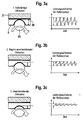
- the FIGS. 3a to 3c show a schematic diagram of the operation of the roller pump, wherein only one of the rollers 25 is shown.
- the rollers 25 are rotatably mounted on a rotor, not shown.
- the tubing, in the present embodiment, the arterial blood line 5, is located between the rollers 25 and a stator 27, which forms a roller conveyor 28 as an abutment.
- FIGS. 3a to 3c show only a schematic representation.
- the roller conveyor extends arcuately around the rotor-wheeled rotor.
- the rollers 25 are resiliently biased against the roller conveyor 28 on the rotor so that the rollers can lift off the hose assembly.
- FIG. 3a shows the case that the rollers 25 completely occlude the tubing
- FIG. 3b the case that the rollers start to lift off the hose
- Figure 3c the case that the tubing is no longer completely occluded by the rollers, so that the blood pump is no longer operated properly.
- the monitoring of the operation of the blood pump is based on the evaluation of the power consumed by the pump.
- the power consumption can be calculated from the product of the voltage applied to the DC electric motor of the blood pump 6 and the current flowing into the motor. But it is also sufficient to determine a correlating with the performance size. Since the voltage can be assumed to be constant, it is sufficient to measure only the motor current. It should be noted that the blood pump can basically also be operated with an AC motor.
- the flow resistance in the dialyzer can increase (clotting). This leads to an increase in the pressure in the arterial blood line 5 upstream of the blood pump 6 and downstream of the dialyzer 1, which, however, can not be measured with the venous pressure sensor 24. With increasing arterial pressure, the power consumption of the blood pump 6 increases.
- An analysis of power consumption shows that the power consumed by the pump or a physical quantity correlating with the power has both a DC component that does not change periodically and a periodically changing AC component.
- FIG. 2 shows the power consumption of the blood pump as a function of time with respect to the DC component and the alternating component (AC).
- the size of the AC power margin is proportional to the magnitude of the DC power consumption as long as the blood pump is completely occluded.
- the curves for this case can be made to coincide.
- FIG. 2 graphically shown during in vitro dialysis treatment with blood substitute.
- the blood substitute was thickened by excessive ultrafiltration until dialyzing of the dialyzer, so that the flow resistance in the dialyzer continuously increased until the resistance force due to the increased back pressure exceeded the restoring forces of the rollers of the pump and the occlusion began to disappear.
- the modulation width of the absorbed power of the motor decreases, although the average power consumption increases due to the high flow resistance in the hose segment.
- FIGS. 3a to 3c show that the amplitude of the AC power consumption decreases with the disappearance of the occlusion, while the DC power consumption increases with the disappearance of the occlusion.
- the arithmetic and evaluation unit 20 are the sizes given in equation 3 available.
- the venous pressure P ven is measured with the venous pressure gauge 24 while the blood pump 6 is operated at the minimum delivery rate, the current I p1 being measured by the control unit 16.
- the pressure in the arterial blood line 6 P Okk which is dependent on the pump type, is assumed to be between 1.6 and 1.8 bar.
- the arterial pressure in the arterial blood line 5 is continuously calculated by the arithmetic and evaluation unit 20 according to equation 3.
- the arithmetic and evaluation unit 20 continuously determines the direct component (DC power consumption) and alternating component (AC power consumption) during the blood treatment from the power consumption or a physical quantity correlated with the power consumption, in particular from the pump current.
- the alternating component is based on the frequency resulting from the product of rotor frequency and number of coils. As long as the blood pump completely occludes the tubing, the quotient of the temporal change in the amplitude of the AC power consumption A AC and the time change of the DC power consumption I DC is constant, ie the slopes of the amplitude modulation A AC and the value of the average DC absorption I DC run in a linear relationship to each other.
- I DC 1 T ⁇ ⁇ T ⁇ I t ⁇ dt
- a AC 1 T ⁇ ⁇ T ⁇ I t ⁇ sin 2 ⁇ ⁇ ⁇ t T + ⁇ ⁇ dt
- the arithmetic and evaluation unit 20 continuously calculates the quotient of the time change of the AC power consumption A AC and the DC power consumption I DC according to Equation 4.
- the arithmetic and evaluation unit has the required arithmetic operations, in particular for the formation of the differentials 20 via a microprocessor.
- the calculated quotient compares the computing and evaluation unit 20 with predetermined limits. In the event that the determined quotient is greater than a first predetermined limit value, ie constant (equation 4), it is assumed that the blood pump 6 completely occludes the arterial blood line 5 (FIG. Fig. 3a ). However, if the first limit value is undershot, the arithmetic and evaluation unit 20 generates a first alarm signal, so that the alarm unit 23 gives a first visual and / or audible alarm, which signals that the rollers of the blood pump start to lift off the hose line ( Fig. 3b ).
- a first predetermined limit value ie constant (equation 4)
- the arithmetic and evaluation unit 20 generates a first alarm signal, so that the alarm unit 23 gives a first visual and / or audible alarm, which signals that the rollers of the blood pump start to lift off the hose line ( Fig. 3b ).
- the arithmetic and evaluation unit If a further second limit value, which is smaller than the first limit value, is reached, the arithmetic and evaluation unit generates a second alarm signal, so that the alarm device gives a second alarm, which signals that the blood pump no longer completely occludes the hose line ( Fig. 3c ). Then a proper operation of the peristaltic pump is no longer given, since the pressure in the arterial blood line 5 has exceeded a predetermined limit due to an increase in the flow resistance in the dialyzer 1.
- An alternative embodiment provides that the quotient is not compared with a limit value, but the temporal change of the DC and AC components of the power consumption at predetermined time intervals, i. logically correlate the amount of increase (slope) of the quantities as follows.
Landscapes
- Engineering & Computer Science (AREA)
- Health & Medical Sciences (AREA)
- Mechanical Engineering (AREA)
- General Engineering & Computer Science (AREA)
- Heart & Thoracic Surgery (AREA)
- Urology & Nephrology (AREA)
- Anesthesiology (AREA)
- Vascular Medicine (AREA)
- Emergency Medicine (AREA)
- Biomedical Technology (AREA)
- Hematology (AREA)
- Life Sciences & Earth Sciences (AREA)
- Animal Behavior & Ethology (AREA)
- General Health & Medical Sciences (AREA)
- Public Health (AREA)
- Veterinary Medicine (AREA)
- External Artificial Organs (AREA)
- Reciprocating Pumps (AREA)
Claims (16)
- Procédé pour actionner une pompe péristaltique électrique (6) pour acheminer un fluide dans une conduite tubulaire (5, 7) dans lequel, pendant le fonctionnement de la pompe (6), le débit absorbé par la pompe ou une grandeur physique corrélée au débit est déterminé(e), caractérisé en ce que, à partir de la grandeur physique mesurée, une composante continue (DC) qui ne se modifie pas périodiquement, et une composante alternative (AC) superposée à la composante continue, qui se modifie périodiquement, sont déterminées, dans lequel on conclut sur la base de la composante continue et de la composante alternative pendant le fonctionnement de la pompe péristaltique, à un fonctionnement anormal de la pompe péristaltique.
- Procédé selon la revendication 1, caractérisé en ce que, pendant le fonctionnement de la pompe péristaltique, la modification temporelle de la composante continue (d/dt I DC) et la modification temporelle de la composante alternative (d/dt AAC) sont en rapport à intervalles temporels prédéter-minés, dans lequel on conclut sur la base de la modification temporelle du rapport déterminé entre la modification temporelle de la composante conti-nue et de la composante alternative, à intervalles temporels prédéterminés pendant le fonctionnement de la pompe péristaltique, à un fonctionnement anormal de la pompe péristaltique.
- Procédé selon la revendication 2, caractérisé en ce que le quotient (dAAC/d I DC) de la modifi-cation temporelle de la composante alternative (d/dt AAC) et de la composante continue (d/dt I DC) est calculé à intervalles temporels prédéterminés et est comparé à une valeur seuil prédéterminée, dans lequel on conclut à une occlusion insuffi-sante de la pompe péristaltique lorsque le quotient dépasse la valeur seuil prédéterminée.
- Procédé selon la revendication 1, caractérisé en ce que le quotient (AAC/I DC) de la composante alternative (AAC) et de la composante continue (I DC) est calculé à intervalles temporels prédéter-minés et est comparé à une valeur seuil prédéter-minée, dans lequel on conclut à une occlusion insuffisante de la pompe péristaltique lorsque le quotient est inférieur à la valeur seuil prédé-terminée.
- Procédé selon l'une des revendications 1 à 4, caractérisé en ce que la pompe péristaltique est une pompe à rouleaux occlusive, la conduite tubu-laire étant disposée entre un stator qui forme un transporteur à rouleaux comme contre-palier et un rotor équipé de rouleaux montés de façon à pou-voir tourner.
- Procédé selon l'une des revendications 1 à 5, caractérisé en ce que, à partir de la grandeur physique corrélée au débit, la pression est déterminée en aval de la pompe péristaltique.
- Procédé selon l'une des revendications 1 à 6, caractérisé en ce qu'une pompe péristaltique électrique d'un dispositif de traitement sanguin extracorporel est actionnée.
- Procédé selon l'une des revendications 1 à 7, caractérisé en ce que la pompe péristaltique est disposée dans une conduite tubulaire artérielle qui conduit à une unité de traitement du sang de laquelle part une conduite tubulaire veineuse, les conduites tubulaires artérielle et veineuse formant ensemble avec l'unité de traitement du sang, une circulation sanguine extracorporelle.
- Dispositif d'actionnement d'une pompe péris-taltique électrique (6) pour acheminer un fluide dans une conduite tubulaire (5, 7) comportant
des moyens (16, 20)de détermination du débit absorbé par la pompe pendant le fonctionnement de la pompe ou une grandeur physique corrélée au débit,
caractérisé en ce que le dispositif présente:- des moyens (16, 20) de détermination d'une com-posante continue (DC) qui ne se modifie pas périodiquement, et d'une composante alternative (AC) qui se modifie périodiquement, à partir de la grandeur physique mesurée, et- des moyens (16, 20) de constatation d'une fonc-tionnement anormal de la pompe péristaltique qui sont conçus de telle sorte que, sur la base de la composante continue (DC) et de la composante alternative (AC) pendant le fonctionnement de la pompe péristaltique, on conclut à un fonction-nement anormal de la pompe péristaltique. - Dispositif selon la revendication 9, caracté-risé en ce que les moyens (16, 20) de constata-tion d'un fonctionnement anormal de la pompe sont conçus de telle sorte que la modification temporelle de la composante continue (d/dt I DC) et la modification temporelle de la composante alterna-tive (d/dt AAC) à intervalles temporels prédéter-minés pendant le fonctionnement de la pompe péristaltique sont en rapport l'une avec l'autre, dans lequel on conclut sur la base de la modifi-cation temporelle du rapport déterminé entre la modification temporelle de la composante continue et de la composante alternative, à intervalles prédéterminés pendant le fonctionnement de la pompe péristaltique, à un fonctionnement anormal de la pompe péristaltique.
- Dispositif selon la revendication 10, carac-térisé en ce que les moyens (16, 20) de constata-tion d'un fonctionnement anormal de la pompe péristaltique sont conçus de telle sorte que le quotient (dAAC/d I DC) de la modification tempo-relle de la composante alternative (d/dt AAC) et de la composante continue (d/dt I DC) est calculé à intervalles temporels prédéterminés pendant le fonctionnement de la pompe péristaltique et est comparé à une valeur seuil prédéterminée, dans lequel on conclut à une occlusion insuffisante de la pompe péristaltique lorsque le quotient dépasse la valeur seuil prédéterminée.
- Dispositif selon la revendication 9, carac-térisé en ce que les moyens (16, 20) de constata-tion d'un fonctionnement anormal de la pompe péristaltique sont conçus de telle sorte que le quotient (AAC/I DC) de la composante alternative (AAC) et de la composante continue (I DC) est cal-culé à intervalles temporels prédéterminés pendant le fonctionnement de la pompe péristaltique et est comparé à une valeur seuil prédéterminée, dans lequel on conclut à une occlusion insuf-fisante de la pompe péristaltique lorsque le quotient est inférieur à la valeur seuil prédé-terminée.
- Dispositif selon l'une des revendications 9 à 12, caractérisé en ce que la pompe péristaltique est une pompe à rouleaux occlusive (6), la con-duite tubulaire étant disposée entre un stator qui forme un transporteur à rouleaux comme contre-palier et un rotor équipé de rouleaux montés de façon à pouvoir tourner.
- Dispositif selon l'une des revendications 9 à 13, caractérisé en ce que le dispositif présente des moyens (13) pour déterminer la pression en aval de la pompe péristaltique qui est conçue de telle sorte qu'à partir de la grandeur physique corrélée au débit, la pression est déterminée en aval de la pompe péristaltique.
- Dispositif de traitement du sang avec une pompe péristaltique. électrique (6), caractérisé en ce que le dispositif de traitement du sang présente un dispositif selon l'une des revendications 9 à 14 pour faire fonctionner la pompe péristaltique (6).
- Dispositif de traitement du sang selon la revendication 15, caractérisé en ce que le dispositif de traitement du sang présente une unité de traitement du sang (1) à laquelle conduit une conduite tubulaire artérielle (5) et de laquelle part une conduite tubulaire veineuse (7), la pompe péristaltique électrique (6) étant disposée dans la conduite tubulaire artérielle (5).
Priority Applications (1)
| Application Number | Priority Date | Filing Date | Title |
|---|---|---|---|
| PL07711730T PL1994284T3 (pl) | 2006-03-11 | 2007-03-01 | Sposób i urządzenie do sterowania pracą elektrycznej perystaltycznej pompy przewodowej |
Applications Claiming Priority (2)
| Application Number | Priority Date | Filing Date | Title |
|---|---|---|---|
| DE102006011346A DE102006011346A1 (de) | 2006-03-11 | 2006-03-11 | Verfahren und Vorrichtung zum Betreiben einer elektrischen peristaltischen Schlauchpumpe |
| PCT/EP2007/001754 WO2007104435A2 (fr) | 2006-03-11 | 2007-03-01 | Procédé et dispositif pour faire fonctionner une pompe peristaltique électrique |
Publications (2)
| Publication Number | Publication Date |
|---|---|
| EP1994284A2 EP1994284A2 (fr) | 2008-11-26 |
| EP1994284B1 true EP1994284B1 (fr) | 2011-05-04 |
Family
ID=38336090
Family Applications (1)
| Application Number | Title | Priority Date | Filing Date |
|---|---|---|---|
| EP07711730A Active EP1994284B1 (fr) | 2006-03-11 | 2007-03-01 | Procédé et dispositif pour faire fonctionner une pompe peristaltique électrique |
Country Status (9)
| Country | Link |
|---|---|
| US (1) | US8043076B2 (fr) |
| EP (1) | EP1994284B1 (fr) |
| JP (1) | JP5235688B2 (fr) |
| CN (1) | CN101400894B (fr) |
| AT (1) | ATE508278T1 (fr) |
| DE (2) | DE102006011346A1 (fr) |
| ES (1) | ES2365541T3 (fr) |
| PL (1) | PL1994284T3 (fr) |
| WO (1) | WO2007104435A2 (fr) |
Families Citing this family (13)
| Publication number | Priority date | Publication date | Assignee | Title |
|---|---|---|---|---|
| DE102008039022B4 (de) * | 2008-08-21 | 2014-08-28 | Fresenius Medical Care Deutschland Gmbh | Verfahren und Vorrichtung zum Überwachen einer peristaltischen Schlauchpumpe zur Förderung einer Flüssigkeit in einer Schlauchleitung |
| DE102009057858B4 (de) * | 2009-12-11 | 2011-09-22 | Fresenius Medical Care Deutschland Gmbh | Vorrichtung und Verfahren zur Überwachung einer im Flüssigkeitssystem einer extrakorporalen Blutbehandlungsvorrichtung angeordneten elektrisch betriebenen Pumpe |
| DE102010033241A1 (de) | 2010-08-03 | 2012-02-09 | Fresenius Medical Care Deutschland Gmbh | Vorrichtung mit einer Schlauchrollenpumpe sowie Verfahren hierzu |
| DE102011103325A1 (de) * | 2011-06-03 | 2012-12-06 | Fresenius Medical Care Deutschland Gmbh | Verfahren zur Einstellung eines kontinuierlichen Dialysatvolumenstromes in einer Dialysemaschine und Dialysemaschine |
| DE102011108778B4 (de) | 2011-07-29 | 2018-05-09 | Fresenius Medical Care Deutschland Gmbh | Verfahren sowie Vorrichtungen zum Erfassen einer Durchlässigkeit eines in eine Schlauchpumpe eingelegten Schlauchs |
| CN103874855B (zh) * | 2011-10-21 | 2016-11-16 | 费森尤斯维亚尔两合公司 | 泵送液体的蠕动泵以及操作蠕动泵的方法 |
| DE102013006562A1 (de) * | 2013-04-16 | 2014-10-16 | Fresenius Medical Care Deutschland Gmbh | Verfahren zur Ermittlung des Druckes in einem extrakorporalen Kreislauf |
| DE102013008720B4 (de) * | 2013-05-23 | 2019-05-09 | Fresenius Medical Care Deutschland Gmbh | Verfahren und Vorrichtung zur Überwachung eines extrakorporalen Blutkreislaufs |
| DE102015105323A1 (de) * | 2015-04-08 | 2016-10-13 | B. Braun Avitum Ag | Fluidförderungsüberwachungsverfahren in einer extrakorporalen Blutbehandlungsvorrichtung |
| CN105363084B (zh) * | 2015-12-10 | 2018-06-26 | 威海威高血液净化制品有限公司 | 一种血液净化装置的液体平衡系统及应用 |
| CN108367107B (zh) * | 2015-12-14 | 2020-09-29 | 心脏器械股份有限公司 | 具有重启锁定的血泵 |
| DE102016005467A1 (de) | 2016-05-06 | 2017-11-09 | Fresenius Medical Care Deutschland Gmbh | Medizinische Behandlungsvorrichtung und Schlauchset für eine medizinische Behandlungsvorrichtung sowie Verfahren zur Überwachung einer peristaltischen Schlauchpumpe |
| CN108457845A (zh) * | 2018-04-02 | 2018-08-28 | 汉仲坤(上海)控制系统有限公司 | 智能软管泵 |
Family Cites Families (10)
| Publication number | Priority date | Publication date | Assignee | Title |
|---|---|---|---|---|
| US4781525A (en) * | 1987-07-17 | 1988-11-01 | Minnesota Mining And Manufacturing Company | Flow measurement system |
| US4884013A (en) * | 1988-01-15 | 1989-11-28 | Sherwood Medical Company | Motor unit for a fluid pump and method of operation |
| IT1250558B (it) * | 1991-12-30 | 1995-04-20 | Hospal Dasco Spa | Macchina per dialisi con controllo della sicurezza e relativo metodo di controllo della sicurezza. |
| US5438510A (en) | 1993-03-03 | 1995-08-01 | Deka Products Limited Partnership | User interface and monitoring functions for automated peritoneal dialysis systems |
| US5827219A (en) * | 1993-10-28 | 1998-10-27 | Medrad, Inc. | Injection system and pumping system for use therein |
| US5629871A (en) * | 1995-06-07 | 1997-05-13 | Cobe Laboratories, Inc. | Wear trend analysis technique for components of a dialysis machine |
| US5813972A (en) * | 1996-09-30 | 1998-09-29 | Minnesota Mining And Manufacturing Company | Medical perfusion system with data communications network |
| US6783328B2 (en) | 1996-09-30 | 2004-08-31 | Terumo Cardiovascular Systems Corporation | Method and apparatus for controlling fluid pumps |
| WO2001088376A1 (fr) * | 2000-05-18 | 2001-11-22 | Carl Freudenberg Kg | Procede et dispositif de detection de parametres d'exploitation de pompes d'une unite de refoulement a membrane |
| DE10259437B3 (de) * | 2002-12-19 | 2004-09-16 | Fresenius Medical Care Deutschland Gmbh | Verfahren und Vorrichtung zur Bestimmung des Blutflusses in einer blutführenden Leitung |
-
2006
- 2006-03-11 DE DE102006011346A patent/DE102006011346A1/de not_active Ceased
-
2007
- 2007-03-01 AT AT07711730T patent/ATE508278T1/de active
- 2007-03-01 ES ES07711730T patent/ES2365541T3/es active Active
- 2007-03-01 DE DE502007007127T patent/DE502007007127D1/de active Active
- 2007-03-01 US US12/282,544 patent/US8043076B2/en active Active
- 2007-03-01 JP JP2008558674A patent/JP5235688B2/ja not_active Expired - Fee Related
- 2007-03-01 WO PCT/EP2007/001754 patent/WO2007104435A2/fr active Application Filing
- 2007-03-01 EP EP07711730A patent/EP1994284B1/fr active Active
- 2007-03-01 CN CN2007800085135A patent/CN101400894B/zh active Active
- 2007-03-01 PL PL07711730T patent/PL1994284T3/pl unknown
Also Published As
| Publication number | Publication date |
|---|---|
| CN101400894A (zh) | 2009-04-01 |
| JP2009529391A (ja) | 2009-08-20 |
| ATE508278T1 (de) | 2011-05-15 |
| JP5235688B2 (ja) | 2013-07-10 |
| CN101400894B (zh) | 2010-10-13 |
| PL1994284T3 (pl) | 2011-09-30 |
| US20090053083A1 (en) | 2009-02-26 |
| DE502007007127D1 (de) | 2011-06-16 |
| WO2007104435A3 (fr) | 2007-11-01 |
| ES2365541T3 (es) | 2011-10-06 |
| EP1994284A2 (fr) | 2008-11-26 |
| US8043076B2 (en) | 2011-10-25 |
| WO2007104435A2 (fr) | 2007-09-20 |
| DE102006011346A1 (de) | 2007-09-13 |
Similar Documents
| Publication | Publication Date | Title |
|---|---|---|
| EP1994284B1 (fr) | Procédé et dispositif pour faire fonctionner une pompe peristaltique électrique | |
| EP2320970B1 (fr) | Procédé et dispositif de surveillance d'une pompe péristaltique pour le refoulement d'un liquide dans un tuyau flexible | |
| EP1584339B1 (fr) | Procédé et dispositif de surveillance d'un accès à un vaisseau sanguin | |
| EP2519282B1 (fr) | Dispositif et procédé de surveillance d'un traitement sanguin extracorporel | |
| EP1327457B1 (fr) | Dispositif pour détecter une fuite dans un circuit de liquide d'un appareil de traitement du sang | |
| EP1595560B1 (fr) | Méthode et dispositif pour surveiller l'adduction de liquide de substitution pendant un traitement extracorporel du sang | |
| DE102011112221B4 (de) | Blutbehandlungsvorrichtung | |
| EP2040776B1 (fr) | Procédé et dispositif de surveillance d'un circuit de circulation sanguine extracorporel | |
| EP1356836B1 (fr) | Appareil pour traitement extracorporel du sang | |
| EP3452135B1 (fr) | Dispositif de traitement médical et ensemble de tuyaux souples pour un dispositif de traitement médical | |
| DE102010033241A1 (de) | Vorrichtung mit einer Schlauchrollenpumpe sowie Verfahren hierzu | |
| EP3078390B1 (fr) | Procede de surveillance d'acheminement de fluide dans un dispositif de traitement de sang extracorporel | |
| EP2432518B1 (fr) | Dispositif et procédé pour reconnaître un système de conduite flexible pour un dispositif de traitement extracorporel du sang | |
| EP1480695A1 (fr) | Procede et dispositif de determination du taux d'hematocrite et/ou du volume sanguin | |
| DE10033192B4 (de) | Verfahren zur Detektion arterieller Einlaufprobleme während einer extrakorporalen Blutbehandlung und extrakorporale Blutbehandlungsvorrichtung | |
| EP3024511B1 (fr) | Dispositif de traitement extracorporel du sang | |
| DE102008057994A1 (de) | Verfahren und Vorrichtung zur Erkennung einer paravasalen Blutung | |
| EP2986332B1 (fr) | Procédé de détermination de la pression dans une circulation extracorporelle | |
| EP3365044B1 (fr) | Dispositif, système et procédé pour la détection basée sur la pression d'un caillot | |
| DE102018108492A1 (de) | Blutschlauchsatz, Steuer- oder Regelvorrichtung, Blutbehandlungsvorrichtung und Verfahren für die Single Needle-Behandlung | |
| DE102013020747A1 (de) | Vorrichtung und Verfahren zur Überwachung des venösen Gefäßzugangs bei einer extrakorporalen Blutbehandlung | |
| EP2509653B1 (fr) | Dispositif et procédé de surveillance d'une pompe à fonctionnement électrique disposée dans le système de liquide d'un dispositif de traitement extracorporel du sang |
Legal Events
| Date | Code | Title | Description |
|---|---|---|---|
| PUAI | Public reference made under article 153(3) epc to a published international application that has entered the european phase |
Free format text: ORIGINAL CODE: 0009012 |
|
| 17P | Request for examination filed |
Effective date: 20080902 |
|
| AK | Designated contracting states |
Kind code of ref document: A2 Designated state(s): AT BE BG CH CY CZ DE DK EE ES FI FR GB GR HU IE IS IT LI LT LU LV MC NL PL PT RO SE SI SK TR |
|
| GRAP | Despatch of communication of intention to grant a patent |
Free format text: ORIGINAL CODE: EPIDOSNIGR1 |
|
| DAX | Request for extension of the european patent (deleted) | ||
| RBV | Designated contracting states (corrected) |
Designated state(s): AT BE BG CH CY CZ DE DK EE ES FI FR GB GR HU IE IS IT LI LT LU LV MC MT NL PL PT RO SE SI SK TR |
|
| GRAS | Grant fee paid |
Free format text: ORIGINAL CODE: EPIDOSNIGR3 |
|
| GRAA | (expected) grant |
Free format text: ORIGINAL CODE: 0009210 |
|
| AK | Designated contracting states |
Kind code of ref document: B1 Designated state(s): AT BE BG CH CY CZ DE DK EE ES FI FR GB GR HU IE IS IT LI LT LU LV MC MT NL PL PT RO SE SI SK TR |
|
| REG | Reference to a national code |
Ref country code: GB Ref legal event code: FG4D Free format text: NOT ENGLISH |
|
| REG | Reference to a national code |
Ref country code: CH Ref legal event code: EP |
|
| REG | Reference to a national code |
Ref country code: IE Ref legal event code: FG4D Free format text: LANGUAGE OF EP DOCUMENT: GERMAN |
|
| REF | Corresponds to: |
Ref document number: 502007007127 Country of ref document: DE Date of ref document: 20110616 Kind code of ref document: P |
|
| REG | Reference to a national code |
Ref country code: DE Ref legal event code: R096 Ref document number: 502007007127 Country of ref document: DE Effective date: 20110616 |
|
| REG | Reference to a national code |
Ref country code: SE Ref legal event code: TRGR |
|
| REG | Reference to a national code |
Ref country code: NL Ref legal event code: VDEP Effective date: 20110504 |
|
| REG | Reference to a national code |
Ref country code: PL Ref legal event code: T3 |
|
| REG | Reference to a national code |
Ref country code: ES Ref legal event code: FG2A Ref document number: 2365541 Country of ref document: ES Kind code of ref document: T3 Effective date: 20111006 |
|
| PG25 | Lapsed in a contracting state [announced via postgrant information from national office to epo] |
Ref country code: LT Free format text: LAPSE BECAUSE OF FAILURE TO SUBMIT A TRANSLATION OF THE DESCRIPTION OR TO PAY THE FEE WITHIN THE PRESCRIBED TIME-LIMIT Effective date: 20110504 Ref country code: PT Free format text: LAPSE BECAUSE OF FAILURE TO SUBMIT A TRANSLATION OF THE DESCRIPTION OR TO PAY THE FEE WITHIN THE PRESCRIBED TIME-LIMIT Effective date: 20110905 |
|
| PG25 | Lapsed in a contracting state [announced via postgrant information from national office to epo] |
Ref country code: IS Free format text: LAPSE BECAUSE OF FAILURE TO SUBMIT A TRANSLATION OF THE DESCRIPTION OR TO PAY THE FEE WITHIN THE PRESCRIBED TIME-LIMIT Effective date: 20110904 Ref country code: SI Free format text: LAPSE BECAUSE OF FAILURE TO SUBMIT A TRANSLATION OF THE DESCRIPTION OR TO PAY THE FEE WITHIN THE PRESCRIBED TIME-LIMIT Effective date: 20110504 Ref country code: LV Free format text: LAPSE BECAUSE OF FAILURE TO SUBMIT A TRANSLATION OF THE DESCRIPTION OR TO PAY THE FEE WITHIN THE PRESCRIBED TIME-LIMIT Effective date: 20110504 Ref country code: CY Free format text: LAPSE BECAUSE OF FAILURE TO SUBMIT A TRANSLATION OF THE DESCRIPTION OR TO PAY THE FEE WITHIN THE PRESCRIBED TIME-LIMIT Effective date: 20110504 Ref country code: FI Free format text: LAPSE BECAUSE OF FAILURE TO SUBMIT A TRANSLATION OF THE DESCRIPTION OR TO PAY THE FEE WITHIN THE PRESCRIBED TIME-LIMIT Effective date: 20110504 Ref country code: GR Free format text: LAPSE BECAUSE OF FAILURE TO SUBMIT A TRANSLATION OF THE DESCRIPTION OR TO PAY THE FEE WITHIN THE PRESCRIBED TIME-LIMIT Effective date: 20110805 |
|
| REG | Reference to a national code |
Ref country code: IE Ref legal event code: FD4D |
|
| PG25 | Lapsed in a contracting state [announced via postgrant information from national office to epo] |
Ref country code: NL Free format text: LAPSE BECAUSE OF FAILURE TO SUBMIT A TRANSLATION OF THE DESCRIPTION OR TO PAY THE FEE WITHIN THE PRESCRIBED TIME-LIMIT Effective date: 20110504 |
|
| PG25 | Lapsed in a contracting state [announced via postgrant information from national office to epo] |
Ref country code: IE Free format text: LAPSE BECAUSE OF FAILURE TO SUBMIT A TRANSLATION OF THE DESCRIPTION OR TO PAY THE FEE WITHIN THE PRESCRIBED TIME-LIMIT Effective date: 20110504 Ref country code: CZ Free format text: LAPSE BECAUSE OF FAILURE TO SUBMIT A TRANSLATION OF THE DESCRIPTION OR TO PAY THE FEE WITHIN THE PRESCRIBED TIME-LIMIT Effective date: 20110504 Ref country code: EE Free format text: LAPSE BECAUSE OF FAILURE TO SUBMIT A TRANSLATION OF THE DESCRIPTION OR TO PAY THE FEE WITHIN THE PRESCRIBED TIME-LIMIT Effective date: 20110504 |
|
| PG25 | Lapsed in a contracting state [announced via postgrant information from national office to epo] |
Ref country code: SK Free format text: LAPSE BECAUSE OF FAILURE TO SUBMIT A TRANSLATION OF THE DESCRIPTION OR TO PAY THE FEE WITHIN THE PRESCRIBED TIME-LIMIT Effective date: 20110504 Ref country code: DK Free format text: LAPSE BECAUSE OF FAILURE TO SUBMIT A TRANSLATION OF THE DESCRIPTION OR TO PAY THE FEE WITHIN THE PRESCRIBED TIME-LIMIT Effective date: 20110504 Ref country code: RO Free format text: LAPSE BECAUSE OF FAILURE TO SUBMIT A TRANSLATION OF THE DESCRIPTION OR TO PAY THE FEE WITHIN THE PRESCRIBED TIME-LIMIT Effective date: 20110504 |
|
| PLBE | No opposition filed within time limit |
Free format text: ORIGINAL CODE: 0009261 |
|
| STAA | Information on the status of an ep patent application or granted ep patent |
Free format text: STATUS: NO OPPOSITION FILED WITHIN TIME LIMIT |
|
| 26N | No opposition filed |
Effective date: 20120207 |
|
| REG | Reference to a national code |
Ref country code: DE Ref legal event code: R097 Ref document number: 502007007127 Country of ref document: DE Effective date: 20120207 |
|
| BERE | Be: lapsed |
Owner name: FRESENIUS MEDICAL CARE DEUTSCHLAND G.M.B.H. Effective date: 20120331 |
|
| PG25 | Lapsed in a contracting state [announced via postgrant information from national office to epo] |
Ref country code: MC Free format text: LAPSE BECAUSE OF NON-PAYMENT OF DUE FEES Effective date: 20120331 |
|
| REG | Reference to a national code |
Ref country code: CH Ref legal event code: PL |
|
| PG25 | Lapsed in a contracting state [announced via postgrant information from national office to epo] |
Ref country code: LI Free format text: LAPSE BECAUSE OF NON-PAYMENT OF DUE FEES Effective date: 20120331 Ref country code: BE Free format text: LAPSE BECAUSE OF NON-PAYMENT OF DUE FEES Effective date: 20120331 Ref country code: CH Free format text: LAPSE BECAUSE OF NON-PAYMENT OF DUE FEES Effective date: 20120331 |
|
| REG | Reference to a national code |
Ref country code: AT Ref legal event code: MM01 Ref document number: 508278 Country of ref document: AT Kind code of ref document: T Effective date: 20120301 |
|
| PG25 | Lapsed in a contracting state [announced via postgrant information from national office to epo] |
Ref country code: BG Free format text: LAPSE BECAUSE OF FAILURE TO SUBMIT A TRANSLATION OF THE DESCRIPTION OR TO PAY THE FEE WITHIN THE PRESCRIBED TIME-LIMIT Effective date: 20110804 |
|
| PG25 | Lapsed in a contracting state [announced via postgrant information from national office to epo] |
Ref country code: MT Free format text: LAPSE BECAUSE OF FAILURE TO SUBMIT A TRANSLATION OF THE DESCRIPTION OR TO PAY THE FEE WITHIN THE PRESCRIBED TIME-LIMIT Effective date: 20110504 Ref country code: AT Free format text: LAPSE BECAUSE OF NON-PAYMENT OF DUE FEES Effective date: 20120301 |
|
| REG | Reference to a national code |
Ref country code: DE Ref legal event code: R082 Ref document number: 502007007127 Country of ref document: DE Representative=s name: MAI, OPPERMANN & PARTNER I. L., DE Ref country code: DE Ref legal event code: R082 Ref document number: 502007007127 Country of ref document: DE Representative=s name: OANDO OPPERMANN & OPPERMANN LLP, DE |
|
| PG25 | Lapsed in a contracting state [announced via postgrant information from national office to epo] |
Ref country code: LU Free format text: LAPSE BECAUSE OF NON-PAYMENT OF DUE FEES Effective date: 20120301 |
|
| PG25 | Lapsed in a contracting state [announced via postgrant information from national office to epo] |
Ref country code: HU Free format text: LAPSE BECAUSE OF FAILURE TO SUBMIT A TRANSLATION OF THE DESCRIPTION OR TO PAY THE FEE WITHIN THE PRESCRIBED TIME-LIMIT Effective date: 20070301 |
|
| REG | Reference to a national code |
Ref country code: DE Ref legal event code: R082 Ref document number: 502007007127 Country of ref document: DE Representative=s name: MAI, OPPERMANN & PARTNER I. L., DE Ref country code: DE Ref legal event code: R082 Ref document number: 502007007127 Country of ref document: DE Representative=s name: OANDO OPPERMANN & OPPERMANN LLP, DE |
|
| REG | Reference to a national code |
Ref country code: DE Ref legal event code: R082 Ref document number: 502007007127 Country of ref document: DE Representative=s name: OANDO OPPERMANN & OPPERMANN LLP, DE |
|
| REG | Reference to a national code |
Ref country code: FR Ref legal event code: PLFP Year of fee payment: 10 |
|
| REG | Reference to a national code |
Ref country code: FR Ref legal event code: PLFP Year of fee payment: 11 |
|
| REG | Reference to a national code |
Ref country code: FR Ref legal event code: PLFP Year of fee payment: 12 |
|
| PGFP | Annual fee paid to national office [announced via postgrant information from national office to epo] |
Ref country code: FR Payment date: 20210218 Year of fee payment: 15 Ref country code: IT Payment date: 20210217 Year of fee payment: 15 |
|
| PGFP | Annual fee paid to national office [announced via postgrant information from national office to epo] |
Ref country code: PL Payment date: 20210222 Year of fee payment: 15 Ref country code: GB Payment date: 20210219 Year of fee payment: 15 Ref country code: TR Payment date: 20210218 Year of fee payment: 15 Ref country code: SE Payment date: 20210223 Year of fee payment: 15 |
|
| PGFP | Annual fee paid to national office [announced via postgrant information from national office to epo] |
Ref country code: ES Payment date: 20210401 Year of fee payment: 15 |
|
| GBPC | Gb: european patent ceased through non-payment of renewal fee |
Effective date: 20220301 |
|
| PG25 | Lapsed in a contracting state [announced via postgrant information from national office to epo] |
Ref country code: SE Free format text: LAPSE BECAUSE OF NON-PAYMENT OF DUE FEES Effective date: 20220302 Ref country code: GB Free format text: LAPSE BECAUSE OF NON-PAYMENT OF DUE FEES Effective date: 20220301 Ref country code: FR Free format text: LAPSE BECAUSE OF NON-PAYMENT OF DUE FEES Effective date: 20220331 |
|
| REG | Reference to a national code |
Ref country code: ES Ref legal event code: FD2A Effective date: 20230427 |
|
| PG25 | Lapsed in a contracting state [announced via postgrant information from national office to epo] |
Ref country code: PL Free format text: LAPSE BECAUSE OF NON-PAYMENT OF DUE FEES Effective date: 20220301 Ref country code: IT Free format text: LAPSE BECAUSE OF NON-PAYMENT OF DUE FEES Effective date: 20220301 |
|
| P01 | Opt-out of the competence of the unified patent court (upc) registered |
Effective date: 20230602 |
|
| PG25 | Lapsed in a contracting state [announced via postgrant information from national office to epo] |
Ref country code: ES Free format text: LAPSE BECAUSE OF NON-PAYMENT OF DUE FEES Effective date: 20220302 |
|
| PGFP | Annual fee paid to national office [announced via postgrant information from national office to epo] |
Ref country code: DE Payment date: 20240220 Year of fee payment: 18 |