EP1994247B1 - A sliding hinged apparatus - Google Patents
A sliding hinged apparatus Download PDFInfo
- Publication number
- EP1994247B1 EP1994247B1 EP07701235.9A EP07701235A EP1994247B1 EP 1994247 B1 EP1994247 B1 EP 1994247B1 EP 07701235 A EP07701235 A EP 07701235A EP 1994247 B1 EP1994247 B1 EP 1994247B1
- Authority
- EP
- European Patent Office
- Prior art keywords
- housing portion
- housing
- lower element
- configuration
- upper element
- Prior art date
- Legal status (The legal status is an assumption and is not a legal conclusion. Google has not performed a legal analysis and makes no representation as to the accuracy of the status listed.)
- Active
Links
- 230000008878 coupling Effects 0.000 claims description 3
- 238000010168 coupling process Methods 0.000 claims description 3
- 238000005859 coupling reaction Methods 0.000 claims description 3
- ORQBXQOJMQIAOY-UHFFFAOYSA-N nobelium Chemical compound [No] ORQBXQOJMQIAOY-UHFFFAOYSA-N 0.000 description 32
- 230000007246 mechanism Effects 0.000 description 21
- 230000033001 locomotion Effects 0.000 description 6
- 230000008901 benefit Effects 0.000 description 5
- 238000000034 method Methods 0.000 description 4
- 238000004891 communication Methods 0.000 description 3
- 230000009471 action Effects 0.000 description 2
- 238000013459 approach Methods 0.000 description 2
- 230000006835 compression Effects 0.000 description 2
- 238000007906 compression Methods 0.000 description 2
- 238000010276 construction Methods 0.000 description 2
- 230000000694 effects Effects 0.000 description 2
- 239000011800 void material Substances 0.000 description 2
- 229920004943 Delrin® Polymers 0.000 description 1
- 238000005452 bending Methods 0.000 description 1
- 230000001413 cellular effect Effects 0.000 description 1
- 239000011248 coating agent Substances 0.000 description 1
- 238000000576 coating method Methods 0.000 description 1
- 230000000295 complement effect Effects 0.000 description 1
- 238000011109 contamination Methods 0.000 description 1
- 239000000428 dust Substances 0.000 description 1
- 230000006870 function Effects 0.000 description 1
- 238000013507 mapping Methods 0.000 description 1
- 238000012986 modification Methods 0.000 description 1
- 230000004048 modification Effects 0.000 description 1
- 239000004033 plastic Substances 0.000 description 1
- 230000007704 transition Effects 0.000 description 1
Images


Classifications
-
- H—ELECTRICITY
- H04—ELECTRIC COMMUNICATION TECHNIQUE
- H04B—TRANSMISSION
- H04B1/00—Details of transmission systems, not covered by a single one of groups H04B3/00 - H04B13/00; Details of transmission systems not characterised by the medium used for transmission
- H04B1/38—Transceivers, i.e. devices in which transmitter and receiver form a structural unit and in which at least one part is used for functions of transmitting and receiving
-
- H—ELECTRICITY
- H04—ELECTRIC COMMUNICATION TECHNIQUE
- H04M—TELEPHONIC COMMUNICATION
- H04M1/00—Substation equipment, e.g. for use by subscribers
- H04M1/02—Constructional features of telephone sets
- H04M1/0202—Portable telephone sets, e.g. cordless phones, mobile phones or bar type handsets
- H04M1/0206—Portable telephones comprising a plurality of mechanically joined movable body parts, e.g. hinged housings
- H04M1/0208—Portable telephones comprising a plurality of mechanically joined movable body parts, e.g. hinged housings characterized by the relative motions of the body parts
- H04M1/0235—Slidable or telescopic telephones, i.e. with a relative translation movement of the body parts; Telephones using a combination of translation and other relative motions of the body parts
- H04M1/0237—Sliding mechanism with one degree of freedom
-
- E—FIXED CONSTRUCTIONS
- E05—LOCKS; KEYS; WINDOW OR DOOR FITTINGS; SAFES
- E05F—DEVICES FOR MOVING WINGS INTO OPEN OR CLOSED POSITION; CHECKS FOR WINGS; WING FITTINGS NOT OTHERWISE PROVIDED FOR, CONCERNED WITH THE FUNCTIONING OF THE WING
- E05F17/00—Special devices for shifting a plurality of wings operated simultaneously
- E05F17/002—Special devices for shifting a plurality of wings operated simultaneously for wings which lie one behind the other when closed
-
- E—FIXED CONSTRUCTIONS
- E05—LOCKS; KEYS; WINDOW OR DOOR FITTINGS; SAFES
- E05Y—INDEXING SCHEME ASSOCIATED WITH SUBCLASSES E05D AND E05F, RELATING TO CONSTRUCTION ELEMENTS, ELECTRIC CONTROL, POWER SUPPLY, POWER SIGNAL OR TRANSMISSION, USER INTERFACES, MOUNTING OR COUPLING, DETAILS, ACCESSORIES, AUXILIARY OPERATIONS NOT OTHERWISE PROVIDED FOR, APPLICATION THEREOF
- E05Y2999/00—Subject-matter not otherwise provided for in this subclass
-
- H—ELECTRICITY
- H04—ELECTRIC COMMUNICATION TECHNIQUE
- H04M—TELEPHONIC COMMUNICATION
- H04M1/00—Substation equipment, e.g. for use by subscribers
- H04M1/02—Constructional features of telephone sets
- H04M1/0202—Portable telephone sets, e.g. cordless phones, mobile phones or bar type handsets
- H04M1/0206—Portable telephones comprising a plurality of mechanically joined movable body parts, e.g. hinged housings
- H04M1/0208—Portable telephones comprising a plurality of mechanically joined movable body parts, e.g. hinged housings characterized by the relative motions of the body parts
- H04M1/0214—Foldable telephones, i.e. with body parts pivoting to an open position around an axis parallel to the plane they define in closed position
Definitions
- the present invention relates generally to sliding devices and, more particularly to sliding devices that have a rotating hinge portion.
- Handheld device are continually being reduced in size and improved to meet consumer size, aesthetic, and performance requirements.
- Slider solution mechanisms permit parts of such devices, such as displays or keypads, to be retracted and hidden when not in use. Slider mechanisms can facilitate miniaturization and offer additional freedom to device designers.
- current sliding mechanisms are complex, bulky, heavy, and expensive. Current sliding mechanisms add significantly to the weight of the devices in which they are incorporated. Further, current sliding mechanisms are relatively thick, making it difficult to incorporate them into aesthetically-pleasing designs.
- Known slider solutions have the main display on the outside of the product, however the ergonomics in the open position are not as good as a clam style (i.e. folding type of form factor).
- the known slider solutions have the following disadvantages: there is an inevitable step, resulting in a difference in heights between the top and bottom housing portions. Therefore the user interface and navigation part of the keypad sits above the numeric element making the overall ergonomics of the keypad poor. The difference in height also makes integrating of the styling between the bottom and top module difficult.
- the products tend to look disjointed. Most slider motions are flat so when placed on a desk they sit flat like a bar. This does not support the video and multi media user cases required for the trend toward higher tier 3G and beyond communication devices.
- US patent no. 5,440,629 describes a portable telephone handset construction having a chassis to which is slidably assembled an end closure which is collapsible to a position for protecting a selected portion of the chassis from contact to minimize its contamination by dust and other debris.
- the end closure When fully extended the end closure may represent an earpiece or mouth piece of the handset construction which is capable of angular orientation relative to the chassis so as to assume the normal configuration of the earpiece or mouth piece of a conventional telephone handset.
- the end closures containing the earpiece and the mouth piece are guided during sliding movement relative to the chassis by means of cooperating guide tracks and guide elements.
- Korean patent application no. 10-2005-0061200 describes a body bending apparatus for a slide-type portable device.
- the present disclosure concerns slider mechanisms for components such as those on portable electronic devices including, for example, laptop computers, portable video players, handheld computers, wireless messaging devices, portable game players, GPS mapping devices, pagers, portable dictionaries, personal digital assistants, cellular telephones, and equivalents and combinations thereof.
- the terms “a” or “an” as used herein are defined as one or more than one.
- the term “plurality” as used herein is defined as two or more than two.
- the term “another” as used herein is defined as at least a second or more.
- the terms “including,” “having” and “has” as used herein are defined as comprising (i.e., open language).
- the term “coupled” as used herein is defined as connected, although not necessarily directly.
- the device is an electronic device such as a radiotelephone.
- the radiotelephone described herein is a representation of the type of wireless communication device that may benefit from the present invention.
- the present invention may be applied to any type of hand-held or portable device including, but not limited to, the following devices: radiotelephones, cordless phones, paging devices, personal digital assistants, portable computers, pen-based or keyboard-based handheld devices, remote control units, portable media players (such as an MP3 or DVD player) that have wireless communication capability and the like.
- any reference herein to the radiotelephone 100 should also be considered to apply equally to other portable wireless electronic devices.
- An electronic device has a first housing portion and a second housing portion that slide and tilt relative to each other to result in compact and extended positions, as well as intermediate positions.
- the slide and tilt mechanism includes an upper element having a top and a bottom and an angled portion located at an end of the upper element, the angled portion angled relative to the bottom of the upper element.
- a lower element having a first lower element portion and a second lower element portion coupled together by a joint, the joint allowing the first lower element portion to fold relative to the second lower element portion and relative to the upper element.
- a slide enabling member coupling the upper element to the lower element such that when the upper element and the lower element are in a closed configuration, the upper element prevents the lower element from folding.
- a biasing member biases the lower element to fold, i.e. rotate about the joint when the upper element is slid to an extended position.
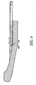
- FIG. 1 illustrates a cross section of the device 101 in a compact, closed or retracted configuration 100.
- FIG. 2 illustrates a cross section of the device 101 in the extended and tilted configuration 200.
- the exemplary device 101 which may be a radiotelephone in this case, includes an upper element 102 and a lower element 104.
- both the upper element and the lower element are planalry adjacent.
- the lower element is laterally off-set from the upper element and a portion of the lower element is folded toward the upper element exposing a top surface 134 of the lower element 104.
- the upper element 102 includes a display 106 and various buttons 120, navigation buttons in this embodiment.
- the upper element 102 also includes a tapered portion 130. The tapered portion is angled relative to a first side 132 of the upper element 102.
- a keypad 202 is carried on the top surface 134 of lower element 104.
- the upper element 102 slides, as indicated by arrow 108 with respect to the lower element 104 to expose the top surface 134 and, in this exemplary embodiment, the keypad 202.
- a user can apply manual force in the longitudinal direction of the device 101 to cause the upper element 102 to slide with respect to the lower element 104 thus causing the keypad 202 to extend and tilt in relation to the upper element 102 from the configuration shown in FIG. 1 or to retract from the configuration shown in FIG. 2 .
- the lower element 104 is made up of two portions, a first lower element portion 122 and a second lower element portion 124 which are longitudinally adjacent (i.e. end to end) and coupled together by a joint 126.
- the upper element 102 is shorter than the lower element 104, wherein the lower element extends beyond the first lower element portion 122.
- the lower element in this embodiment, has a end portion that is complementary in shape to the tapered portion 130 of the upper element 102.
- the upper element 102 and the lower element are substantially the same size and have an elongated shape.
- the first lower element portion 122 bends or rotates relative to the second lower element portion 124 about the joint 126 to angle upward toward the upper element 102 when the upper element 102 is slid to the extended configuration 200.
- the joint 126 is positioned at or near the top surface 134 of the lower element 104.
- the joint may be a hinge, such as a barrel and pin hinge, a resilient member such as rubber or plastic, or the like.
- the joint 126 is positioned so that the first lower element portion 122 and the second lower element portion 124 fold in one direction toward the upper element 102.
- a first upper element portion bottom surface 132 slides in contact with a first lower element portion top surface 134.
- the tapered portion 130 comes in contact with the first lower element portion top surface 134 when the tapered portion 130 approaches the joint 126.
- the tapered portion 130 is a follower that interacts with the lower element portion top surface 134 which a portion thereof is a cam.
- the tapered portion 130 allows the first lower element portion 122 to rotate about the joint 126 in a cam / follower motion. Until the tapered portion 130 substantially reaches the joint 126, the upper element 102 prevents the first lower element portion 122 from rotating, thereby holding the first and second lower element portions in the same plane as shown by the configuration in FIG. 1 .
- the distance between the cam surface of the tapered portion 130 and the top surface 134 of the first lower element portion 122 is between 0.1mm and 0.5mm. In one embodiment the distance is 0.3mm.
- the angle of the tapered, which dictates that angle of the first lower element portion 122 may be between zero and ninety degrees relative to the bottom surface 132. In this exemplary embodiment the angle of the tapered portion is 10 degrees relative to the bottom surface 132 in this exemplary embodiment.
- the tapered portion 130 may provide a mechanical stop, stopping the first lower element portion 122 during rotation at the desired angle for the open configuration 200 of the device 101.
- the angle of the tapered portion 130 dictates the angle of the first lower element portion 122 and the keypad202 thereon.
- the tapered portion 130 allows a top surface 140 of the upper element 102, and hence the buttons 120 disposed thereon to be in close proximity to the top surface 142 of the first lower element portion 122.
- the plane of the top surface 140 of the upper element 102 intersects the top surface 142 of the first lower element portion 122. This provides a substantially continuous surface from the top surface 140 of the upper element 102 to the top surface 142 of the first lower element portion 122.
- the keypad 202 is adjacent to the buttons 120 when the device 101 is in the open configuration 200.
- the user may slide a finger from the keypad 202 to the buttons without having to substantially lift the finger up to the top surface of the upper element 102 which would be the distance equal to the thickness of the upper element 102 at the thickest point This is a function of the thickness of the taper portion at the bottom end 144 of the upper element 102.
- the bottom end 144 of the upper element 102 in FIG. 1 is not to scale and is exaggerated for clarity.
- a first biasing member 128 is coupled between the first lower element portion 122 and the second lower element portion 124.
- the biasing member exerts a force on the first lower element portion 122 and the second lower element portion 124, causing the first lower element portion 122 to rotate about the joint 126 relative to the second element portion 124.
- the first biasing member 128 may be an elastic biasing member (such as an expansion spring, a compression spring, or an elastic band), a cam follower mechanism or the like.
- the biasing member applies a constant bias force to urge the first lower element portion 122 and the second lower element portion 124 to fold together.
- a second biasing member may be employed to assist the upper housing when sliding, into the open and closed position creating a bi-stable effect.
- the second biasing member may be an elastic biasing member (such as an expansion spring, a compression spring, or an elastic band) and a cam (such as a slot or track) having a geometry so as to create the bi-stable effect of urging the first housing portion and the second housing portion out of any intermediate position and toward either the compact or extended position.
- the upper housing carries a bearing such as a wheel 150.
- the wheel is located at the tapered portion 130 of the upper housing 102. Instead of the tapered portion 130 engaging the top surface of the first lower element portion 122, the wheel 150 engages the first lower element portion 122 when the housing is near the open configuration 200.
- One wheel 150 is shown however it is understood that a plurality of wheels may be used.
- the wheel contacts the first lower element portion 122 when the device is substantially in the open / extended configuration.
- the wheel starts off in contact with the first lower element portion 122.
- the wheel rolls along the first lower element portion 122 and reduces the friction between the upper element and the first lower element portion 122 when sliding the two elements relative to one another (i.e. closing the device).
- the first lower element comes in contact with the first surface of the upper element and the wheel and the tapered portion 130 separate from the first lower element portion 122.
- the first lower element 122 and the second lower element rotate or unfold to a substantially flat configuration wherein the first lower element portion 122 and the second lower element portion 124 are longitudinally aligned in substantially the same plane as is shown in the closed position 100.
- a bearing surface may take the place of the wheel 150.
- the bearing surface may be a component or coating made of Delrin® other friction reduced surface or the like.
- a wheel 150 and a bearing surface are used in combination with each other.
- an upper housing bearing surface 132 i.e. the bearing surface is the bottom surface
- a first lower element portion 122 bearing surface 134 the first lower element portion top surface 134 is the bearing surface
- come into contact during sliding As the upper element 102 approaches the closed configuration 100, the contact point between the upper element 102 and the first lower element portion 122 transitions from the wheel to the surfaces, e.g. the bearing surfaces, of the upper element 102 and the first lower element portion 122.
- FIG. 1 An exemplary retaining or latching member 152 is illustrated in FIG. 1 .
- the latching member is carried on the first lower element portion 122 adjacent to the joint 126.
- the latching member engages an upper element latching receptacle (not shown).
- an upper element latching receptacle (not shown).
- the latching member engages the upper element latching receptacle.
- a first biasing member 128 urges the first lower element portion 122 to be in contact with the upper element 102, the biasing force of the first biasing member 128 may be overcome by manual force for example, and therefore may cause the two elements to separate.
- the latching member 152 engages the upper element 102 to hold the upper element 102 to the first lower element portion 122 when the device 101 is in the open configuration 200. As the upper element slide, the latching member 152 slides with a void (not shown) of the upper element.
- FIG.3 A cross section of the device showing an exemplary slide enabling member of the device 101 is illustrated in FIG.3 .
- the exemplary slide enabling member provides a mechanism for the upper element 102 to slideably engage the lower element 104.
- the upper element 102 is slidealy engaged to the second lower element portion 124.
- the slide enabling member in this embodiment, comprises a set of rails 302 and a set of tracks 304 that engage the rails.
- the rails 302 are carried on the second lower element portion 124 and the tracks 304 are carried on the upper element 102.
- the upper element portion 102 slides along the rails 302 between the closed configuration 100 and the open configuration 200.
- the lower element 104 includes overlapping portions at adjacent ends of the first lower element portion 122 and the second lower element portion 124.
- the first lower element portion 122 includes a first lower element overlapping portion 402 and the second lower element portion 124 includes a second lower element overlapping portion 404 that overlap in both the closed position and the open position.
- the first lower element overlapping portion 402 and the second lower element overlapping portion 404 enclose the gap that is created when the first lower element portion 122 rotates away from the second lower element portion 124.
- a flexible boot may also be coupled between the first lower element portion 122 and the second lower element portion 124.
- the flexible boot may be rubber or the like or have an accordion shaped form factor that bellows in and out and the two elements rotate relative to one another.
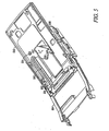
- FIG. 5 One alternative embodiment of the slide and tilt mechanism is illustrated in FIG. 5 having the upper element 502 slideably coupled to a first lower element 504 which hingedly couple to a second lower element 506.
- the upper element 502 is slideably coupled to the first lower element 504 by a rail 505 carried on the upper element 502.
- the upper element includes a slot 508 that is a void which runs longitudinally along the upper element 502.
- a retaining member 510 is carried on the first lower element 504 extending into the slot 508. The top of the retaining member is wider than the slot 508 such that the retaining member 510 will not pass through the slot 508 thereby retaining the upper element 502 to the first lower element 504.
- the retaining member 510 / slot 508 combination prevent the upper element 502 and the first lower element from separating.
- the device comprising a latching member that extends from the first lower element into the slot of the upper element, the latching member slides along the slot retaining the upper member adjacent to the first lower element portion as the upper element is slid from the close configuration to the open configuration.
- the bi-stable biasing member 512 is shown coupled to the upper element 502 and the second lower element 506.
- the bi-stable biasing member 512 is coupled to the upper element 502 by fastener 514 and to the second lower element 506 by fastener 516.
- a method for opening the slide and tilt housing comprises providing a sliding mechanism to allow an upper housing to slide relative to a lower housing, wherein the upper housing is stacked on top of the lower housing.
- the lower housing has first lower housing portion and a second lower housing portion, and the first lower housing portion and a second lower housing portion are coupled together by a hinge.
- the upper housing prevents the first lower housing and the second lower housing form rotating about the hinge when the upper housing is in a closed configuration relative to the lower housing.
- the method further includes providing a rotating mechanism to allow the first lower housing portion to rotate about the hinge to an angled position that is relative to the second lower housing portion and the upper housing when the upper housing is slid to an extended position exposing a keypad of the lower housing.
- the method may also include forming a substantially continuous surface by a upper surface of the lower housing and a upper surface of the upper housing by tilting the lower surface at an angle relative tot eh upper surface.
- the method may include providing a clam like angled flip portion with the angled configuration of the first lower housing portion when the device is in the extended configuration.
- the first lower element portion snaps into place, angled toward the upper element.
Landscapes
- Engineering & Computer Science (AREA)
- Signal Processing (AREA)
- Computer Networks & Wireless Communication (AREA)
- Telephone Set Structure (AREA)
- Casings For Electric Apparatus (AREA)
- Pivots And Pivotal Connections (AREA)
Description
- The present invention relates generally to sliding devices and, more particularly to sliding devices that have a rotating hinge portion.
- Handheld device are continually being reduced in size and improved to meet consumer size, aesthetic, and performance requirements. Slider solution mechanisms permit parts of such devices, such as displays or keypads, to be retracted and hidden when not in use. Slider mechanisms can facilitate miniaturization and offer additional freedom to device designers. However, current sliding mechanisms are complex, bulky, heavy, and expensive. Current sliding mechanisms add significantly to the weight of the devices in which they are incorporated. Further, current sliding mechanisms are relatively thick, making it difficult to incorporate them into aesthetically-pleasing designs.
- Known slider solutions have the main display on the outside of the product, however the ergonomics in the open position are not as good as a clam style (i.e. folding type of form factor). The known slider solutions have the following disadvantages: there is an inevitable step, resulting in a difference in heights between the top and bottom housing portions. Therefore the user interface and navigation part of the keypad sits above the numeric element making the overall ergonomics of the keypad poor. The difference in height also makes integrating of the styling between the bottom and top module difficult. The products tend to look disjointed. Most slider motions are flat so when placed on a desk they sit flat like a bar. This does not support the video and multi media user cases required for the trend toward higher tier 3G and beyond communication devices.
-
US patent no. 5,440,629 describes a portable telephone handset construction having a chassis to which is slidably assembled an end closure which is collapsible to a position for protecting a selected portion of the chassis from contact to minimize its contamination by dust and other debris. When fully extended the end closure may represent an earpiece or mouth piece of the handset construction which is capable of angular orientation relative to the chassis so as to assume the normal configuration of the earpiece or mouth piece of a conventional telephone handset. The end closures containing the earpiece and the mouth piece are guided during sliding movement relative to the chassis by means of cooperating guide tracks and guide elements. - Korean patent application no.
10-2005-0061200 - The various aspects, features and advantages of the present invention will become more fully apparent to those having ordinary skill in the art upon careful consideration of the following Detailed Description of the Invention with the accompanying drawings described below.
- The accompanying figures, where like reference numerals refer to identical or functionally similar elements throughout the separate views and which together with the detailed description below are incorporated in and form part of the specification, serve to further illustrate various embodiments and to explain various principles and advantages all in accordance with the present invention.
-
FIG. 1 is an exemplary cross sectional view of the slide and tilt hinge mechanism in a closed configuration. -
FIG. 2 is an exemplary cross sectional view of the slide and tilt hinge mechanism in an open configuration. -
FIG. 3 is an exemplary cross sectional view of the slide enabling mechanism. -
FIG. 4 is an exemplary cross sectional view of the slide and tilt hinge mechanism in an open configuration. -
FIG. 5 is an exemplary perspective view of a slide and tilt hinge mechanism in an open configuration. - Skilled artisans will appreciate that elements in the figures are illustrated for simplicity and clarity and have not necessarily been drawn to scale. For example, the dimensions of some of the elements in the figures may be exaggerated relative to other elements to help to improve understanding of embodiments of the present invention.
- While the present invention is achievable by various forms of embodiment, there is shown in the drawings and described hereinafter several examples of embodiments with the understanding that the present disclosure is to be considered an exemplification of the invention and is not intended to limit the invention to the specific embodiments contained herein as will become more fully apparent from the discussion below. It is further understood that the apparatus for a slide and tilt hinge of the present invention may be used more generally in any application where it is desirable to provide slideably hinged housings.
- In overview, the present disclosure concerns slider mechanisms for components such as those on portable electronic devices including, for example, laptop computers, portable video players, handheld computers, wireless messaging devices, portable game players, GPS mapping devices, pagers, portable dictionaries, personal digital assistants, cellular telephones, and equivalents and combinations thereof.
- As further discussed below various inventive principles and combinations thereof are advantageously employed to provide a slider mechanism for permitting a component to be moved relative to another component in an electronic device while substantially hiding the apparatus that permits such movement, thus alleviating various problems associated with known sliding mechanisms, provided these principles or equivalents thereof are employed.
- The instant disclosure is provided to further explain in an enabling fashion the best modes of making and using various embodiments in accordance with the present invention. The disclosure is further offered to enhance an understanding and appreciation for the inventive principles and advantages thereof, rather than to limit in any manner the invention. The invention is defined solely by the appended claims including any amendments made during the pendency of this application and all equivalents of those claims as issued.
- Before describing in detail exemplary embodiments that are in accordance with the present invention, it should be observed that the embodiments reside primarily in combinations of apparatus components related to the sliding hinge of an electronic device. Accordingly, the apparatus components have been represented where appropriate by conventional symbols in the drawings, showing only those specific details that are pertinent to understanding the embodiments of the present invention so as not to obscure the disclosure with details that will be readily apparent to those of ordinary skill in the art having the benefit of the description herein.
- It is further understood that the use of relational terms, if any, such as first and second, top and bottom, upper and lower and the like are used solely to distinguish one from another entity or action without necessarily requiring or implying any actual such relationship or order between such entities or actions.
- The terms "a" or "an" as used herein are defined as one or more than one. The term "plurality" as used herein is defined as two or more than two. The term "another" as used herein is defined as at least a second or more. The terms "including," "having" and "has" as used herein are defined as comprising (i.e., open language). The term "coupled" as used herein is defined as connected, although not necessarily directly.
- In this exemplary embodiment, the device is an electronic device such as a radiotelephone. The radiotelephone described herein is a representation of the type of wireless communication device that may benefit from the present invention. However, it is to be understood that the present invention may be applied to any type of hand-held or portable device including, but not limited to, the following devices: radiotelephones, cordless phones, paging devices, personal digital assistants, portable computers, pen-based or keyboard-based handheld devices, remote control units, portable media players (such as an MP3 or DVD player) that have wireless communication capability and the like. Accordingly, any reference herein to the
radiotelephone 100 should also be considered to apply equally to other portable wireless electronic devices. - An electronic device has a first housing portion and a second housing portion that slide and tilt relative to each other to result in compact and extended positions, as well as intermediate positions. The slide and tilt mechanism includes an upper element having a top and a bottom and an angled portion located at an end of the upper element, the angled portion angled relative to the bottom of the upper element. A lower element having a first lower element portion and a second lower element portion coupled together by a joint, the joint allowing the first lower element portion to fold relative to the second lower element portion and relative to the upper element. A slide enabling member, coupling the upper element to the lower element such that when the upper element and the lower element are in a closed configuration, the upper element prevents the lower element from folding. A biasing member, biases the lower element to fold, i.e. rotate about the joint when the upper element is slid to an extended position. A mechanism that permits the sliding and rotating motion is described in detail below.
- An embodiment of an
electronic device 101 incorporating a slide and tilt mechanism is shown inFIG. 1 and FIG. 2. FIG. 1 illustrates a cross section of thedevice 101 in a compact, closed orretracted configuration 100.FIG. 2 illustrates a cross section of thedevice 101 in the extended andtilted configuration 200. - The
exemplary device 101, which may be a radiotelephone in this case, includes anupper element 102 and alower element 104. In the closedconfiguration 100, both the upper element and the lower element are planalry adjacent. In theopen configuration 200, the lower element is laterally off-set from the upper element and a portion of the lower element is folded toward the upper element exposing atop surface 134 of thelower element 104. - The
upper element 102 includes adisplay 106 andvarious buttons 120, navigation buttons in this embodiment. Theupper element 102 also includes atapered portion 130. The tapered portion is angled relative to afirst side 132 of theupper element 102. Akeypad 202 is carried on thetop surface 134 oflower element 104. - The
upper element 102 slides, as indicated byarrow 108 with respect to thelower element 104 to expose thetop surface 134 and, in this exemplary embodiment, thekeypad 202. A user can apply manual force in the longitudinal direction of thedevice 101 to cause theupper element 102 to slide with respect to thelower element 104 thus causing thekeypad 202 to extend and tilt in relation to theupper element 102 from the configuration shown inFIG. 1 or to retract from the configuration shown inFIG. 2 . - The
lower element 104 is made up of two portions, a firstlower element portion 122 and a secondlower element portion 124 which are longitudinally adjacent (i.e. end to end) and coupled together by a joint 126. In this embodiment, theupper element 102 is shorter than thelower element 104, wherein the lower element extends beyond the firstlower element portion 122. The lower element in this embodiment, has a end portion that is complementary in shape to the taperedportion 130 of theupper element 102. In another embodiment, theupper element 102 and the lower element are substantially the same size and have an elongated shape. The firstlower element portion 122 bends or rotates relative to the secondlower element portion 124 about the joint 126 to angle upward toward theupper element 102 when theupper element 102 is slid to theextended configuration 200. - The joint 126 is positioned at or near the
top surface 134 of thelower element 104. The joint may be a hinge, such as a barrel and pin hinge, a resilient member such as rubber or plastic, or the like. The joint 126 is positioned so that the firstlower element portion 122 and the secondlower element portion 124 fold in one direction toward theupper element 102. - When sliding from the
closed configuration 100 to theopen configuration 200, a first upper elementportion bottom surface 132 slides in contact with a first lower element portiontop surface 134. The taperedportion 130 comes in contact with the first lower element portiontop surface 134 when the taperedportion 130 approaches the joint 126. The taperedportion 130 is a follower that interacts with the lower element portiontop surface 134 which a portion thereof is a cam. The taperedportion 130 allows the firstlower element portion 122 to rotate about the joint 126 in a cam / follower motion. Until the taperedportion 130 substantially reaches the joint 126, theupper element 102 prevents the firstlower element portion 122 from rotating, thereby holding the first and second lower element portions in the same plane as shown by the configuration inFIG. 1 . From the fullyclosed configuration 100 to a point prior to theopen configuration 200, the distance between the cam surface of the taperedportion 130 and thetop surface 134 of the firstlower element portion 122 is between 0.1mm and 0.5mm. In one embodiment the distance is 0.3mm. The angle of the tapered, which dictates that angle of the firstlower element portion 122 may be between zero and ninety degrees relative to thebottom surface 132. In this exemplary embodiment the angle of the tapered portion is 10 degrees relative to thebottom surface 132 in this exemplary embodiment. - In addition to providing a follower, the tapered
portion 130 may provide a mechanical stop, stopping the firstlower element portion 122 during rotation at the desired angle for theopen configuration 200 of thedevice 101. In this embodiment, the angle of the taperedportion 130, dictates the angle of the firstlower element portion 122 and the keypad202 thereon. The taperedportion 130 allows atop surface 140 of theupper element 102, and hence thebuttons 120 disposed thereon to be in close proximity to thetop surface 142 of the firstlower element portion 122. The plane of thetop surface 140 of theupper element 102 intersects thetop surface 142 of the firstlower element portion 122. This provides a substantially continuous surface from thetop surface 140 of theupper element 102 to thetop surface 142 of the firstlower element portion 122. This allows for a more seamless user interface because thekeypad 202 is adjacent to thebuttons 120 when thedevice 101 is in theopen configuration 200. For example, the user may slide a finger from thekeypad 202 to the buttons without having to substantially lift the finger up to the top surface of theupper element 102 which would be the distance equal to the thickness of theupper element 102 at the thickest point This is a function of the thickness of the taper portion at thebottom end 144 of theupper element 102. Thebottom end 144 of theupper element 102 inFIG. 1 is not to scale and is exaggerated for clarity. - A
first biasing member 128 is coupled between the firstlower element portion 122 and the secondlower element portion 124. The biasing member exerts a force on the firstlower element portion 122 and the secondlower element portion 124, causing the firstlower element portion 122 to rotate about the joint 126 relative to thesecond element portion 124. Thefirst biasing member 128 may be an elastic biasing member (such as an expansion spring, a compression spring, or an elastic band), a cam follower mechanism or the like. The biasing member applies a constant bias force to urge the firstlower element portion 122 and the secondlower element portion 124 to fold together. - A second biasing member may be employed to assist the upper housing when sliding, into the open and closed position creating a bi-stable effect. The second biasing member may be an elastic biasing member (such as an expansion spring, a compression spring, or an elastic band) and a cam (such as a slot or track) having a geometry so as to create the bi-stable effect of urging the first housing portion and the second housing portion out of any intermediate position and toward either the compact or extended position.
- In one exemplary embodiment, illustrated in
FIG. 1 and FIG. 2 , the upper housing carries a bearing such as awheel 150. The wheel is located at the taperedportion 130 of theupper housing 102. Instead of the taperedportion 130 engaging the top surface of the firstlower element portion 122, thewheel 150 engages the firstlower element portion 122 when the housing is near theopen configuration 200. Onewheel 150 is shown however it is understood that a plurality of wheels may be used. - The wheel contacts the first
lower element portion 122 when the device is substantially in the open / extended configuration. During the closing of thedevice 101, the wheel starts off in contact with the firstlower element portion 122. As the upper element is slid toward theclosed configuration 100, the wheel rolls along the firstlower element portion 122 and reduces the friction between the upper element and the firstlower element portion 122 when sliding the two elements relative to one another (i.e. closing the device). As theupper element 102 is slid towards the close position the first lower element comes in contact with the first surface of the upper element and the wheel and the taperedportion 130 separate from the firstlower element portion 122. During this motion, the firstlower element 122 and the second lower element rotate or unfold to a substantially flat configuration wherein the firstlower element portion 122 and the secondlower element portion 124 are longitudinally aligned in substantially the same plane as is shown in theclosed position 100. - It is understood that a bearing surface may take the place of the
wheel 150. The bearing surface may be a component or coating made of Delrin® other friction reduced surface or the like. In one embodiment, awheel 150 and a bearing surface are used in combination with each other. In this exemplary embodiment, an upper housing bearing surface 132 (i.e. the bearing surface is the bottom surface) and a firstlower element portion 122 bearing surface 134 (the first lower element portiontop surface 134 is the bearing surface) come into contact during sliding. As theupper element 102 approaches theclosed configuration 100, the contact point between theupper element 102 and the firstlower element portion 122 transitions from the wheel to the surfaces, e.g. the bearing surfaces, of theupper element 102 and the firstlower element portion 122. - An exemplary retaining or latching
member 152 is illustrated inFIG. 1 . The latching member is carried on the firstlower element portion 122 adjacent to the joint 126. The latching member engages an upper element latching receptacle (not shown). When theupper element 102 is slide to theopen configuration 200, the latching member engages the upper element latching receptacle. Although afirst biasing member 128 urges the firstlower element portion 122 to be in contact with theupper element 102, the biasing force of thefirst biasing member 128 may be overcome by manual force for example, and therefore may cause the two elements to separate. The latchingmember 152 engages theupper element 102 to hold theupper element 102 to the firstlower element portion 122 when thedevice 101 is in theopen configuration 200. As the upper element slide, the latchingmember 152 slides with a void (not shown) of the upper element. - A cross section of the device showing an exemplary slide enabling member of the
device 101 is illustrated inFIG.3 . The exemplary slide enabling member provides a mechanism for theupper element 102 to slideably engage thelower element 104. In this embodiment, theupper element 102 is slidealy engaged to the secondlower element portion 124. The slide enabling member, in this embodiment, comprises a set ofrails 302 and a set oftracks 304 that engage the rails. Therails 302 are carried on the secondlower element portion 124 and thetracks 304 are carried on theupper element 102. Theupper element portion 102 slides along therails 302 between theclosed configuration 100 and theopen configuration 200. It is understood that one of ordinary skill in the art will appreciate the plurality of slide enabling members that may be incorporated and that the rail and the track are one example. Mechanical stops in combination with the second biasing member, define the points at which the upper housing stops in the open and in the closed configurations. It is also understood that therails 302 may be carried on either theupper element portion 102 or the secondlower element portion 124 and the rail engaging members (e.g. tracks) may be carried on the element that the rails are not carried on. - In one embodiment shown in
FIG. 4 , thelower element 104 includes overlapping portions at adjacent ends of the firstlower element portion 122 and the secondlower element portion 124. The firstlower element portion 122 includes a first lowerelement overlapping portion 402 and the secondlower element portion 124 includes a second lowerelement overlapping portion 404 that overlap in both the closed position and the open position. When the device is configured from theclosed configuration 100 to theopen configuration 200, the first lowerelement overlapping portion 402 and the second lowerelement overlapping portion 404 enclose the gap that is created when the firstlower element portion 122 rotates away from the secondlower element portion 124. - A flexible boot may also be coupled between the first
lower element portion 122 and the secondlower element portion 124. The flexible boot may be rubber or the like or have an accordion shaped form factor that bellows in and out and the two elements rotate relative to one another. - One alternative embodiment of the slide and tilt mechanism is illustrated in
FIG. 5 having theupper element 502 slideably coupled to a firstlower element 504 which hingedly couple to a secondlower element 506. Theupper element 502 is slideably coupled to the firstlower element 504 by arail 505 carried on theupper element 502. The upper element includes aslot 508 that is a void which runs longitudinally along theupper element 502. A retainingmember 510 is carried on the firstlower element 504 extending into theslot 508. The top of the retaining member is wider than theslot 508 such that the retainingmember 510 will not pass through theslot 508 thereby retaining theupper element 502 to the firstlower element 504. As the upper element slides relative to the firstlower element 504, the retainingmember 510 /slot 508 combination prevent theupper element 502 and the first lower element from separating. In this embodiment, the device comprising a latching member that extends from the first lower element into the slot of the upper element, the latching member slides along the slot retaining the upper member adjacent to the first lower element portion as the upper element is slid from the close configuration to the open configuration. Thebi-stable biasing member 512 is shown coupled to theupper element 502 and the secondlower element 506. Thebi-stable biasing member 512 is coupled to theupper element 502 byfastener 514 and to the secondlower element 506 byfastener 516. - A method for opening the slide and tilt housing comprises providing a sliding mechanism to allow an upper housing to slide relative to a lower housing, wherein the upper housing is stacked on top of the lower housing. The lower housing has first lower housing portion and a second lower housing portion, and the first lower housing portion and a second lower housing portion are coupled together by a hinge. The upper housing prevents the first lower housing and the second lower housing form rotating about the hinge when the upper housing is in a closed configuration relative to the lower housing. The method further includes providing a rotating mechanism to allow the first lower housing portion to rotate about the hinge to an angled position that is relative to the second lower housing portion and the upper housing when the upper housing is slid to an extended position exposing a keypad of the lower housing.
- The method may also include forming a substantially continuous surface by a upper surface of the lower housing and a upper surface of the upper housing by tilting the lower surface at an angle relative tot eh upper surface.
- Still further, the method may include providing a clam like angled flip portion with the angled configuration of the first lower housing portion when the device is in the extended configuration. The first lower element portion snaps into place, angled toward the upper element.
- While the present inventions and what is considered presently to be the best modes thereof have been described in a manner that establishes possession thereof by the inventors and that enables those of ordinary skill in the art to make and use the inventions, it will be understood and appreciated that there are many equivalents to the exemplary embodiments disclosed herein and that myriad modifications and variations may be made thereto without departing from the scope of the inventions, which are to be limited not by the exemplary embodiments but by the appended claims.
Claims (8)
- A sliding hinged housing comprising:a first housing portion (122);a second housing portion (124);a third housing portion (102) having a first substantially flat portion and an angled portion (130) located at an end of the third housing portion (102), the third housing portion slideably engaged to the first housing portion (122) by a rail, the sliding hinged housing being
characterized by:the angled portion (130) including a bearing surface (150) that is configured to engage a bearing surface (134) of the first housing portion (122), the bearing surface (134) being provided by a roller (150) coupled to the third housing portion (102);a hinge (126) coupling the first housing portion (122) to the second housing portion (124); anda biasing member (128) coupled between the first housing portion (122) and the second housing portion (124), for biasing the first housing portion (122) to rotate about the hinge (126) relative to the second housing portion (124) in a folded configuration when the third housing portion (102) is in an extended configuration, and wherein the first housing portion (122) and the second housing portion (124) are held in an unfolded configuration when the third housing portion (102) is in a closed configuration. - The housing of claim 1, further comprising latching member (152) that is configured to retain the third housing portion (102) to the first housing portion (122), preventing the first housing portion (122) and the second housing portion (124) from disengaging when the housing is in the open configuration.
- The housing of claim 1, further comprising two rails (302) carried on the second housing portion (124), slideably coupling the second housing portion (124) to the third housing portion (102).
- The housing of claim 1, wherein the angled portion (130) provides a mechanical stop, to configure the angle of the first housing portion (122, 504) when the third housing portion (102, 502) is in the extended configuration.
- The housing of claim 1, wherein the closed configuration comprises the first housing portion (122, 504) and the second housing portion (124, 506) configured longitudinally adjacent.
- The housing of claim 1, further comprising a retaining member (510) that extends from the first housing portion (122, 504) into a slot (508) of the third housing portion (102, 502), the retaining member (510) being configured to slide along the slot (508) retaining the third housing portion (102, 502) adjacent to the first housing portion (122, 504) as the third housing portion (102, 502) is slid from the closed configuration to the extended configuration.
- The housing of claim 1, wherein the third housing portion (102, 502) is configured to slide in a longitudinal direction to the extended configuration and the first housing portion (122, 504) is tilted as a result of the biasing member (128) in a direction toward the third housing portion (102, 502), a portion of the first housing portion (122, 504) contacting the angled portion (130) of the third housing portion (102, 502), and
in a closed position the third housing portion (102, 502) is configured adjacent to both the first (122, 504) and the second (124, 506) housing portions, holding the first housing portion (122, 504) and the second housing portion (124, 506) in a substantially planar configuration. - The housing of claim 1, further comprising an exposed keypad (202) carried on the first housing portion (122, 504) when the third housing portion is in the extended configuration relative to the first (122, 504) and second (124, 506) housing portions.
Applications Claiming Priority (2)
| Application Number | Priority Date | Filing Date | Title |
|---|---|---|---|
| US11/364,373 US7653422B2 (en) | 2006-02-28 | 2006-02-28 | Method and apparatus for a sliding hinge |
| PCT/US2007/060498 WO2007100932A2 (en) | 2006-02-28 | 2007-01-12 | A method and apparatus for a sliding hinge |
Publications (3)
| Publication Number | Publication Date |
|---|---|
| EP1994247A2 EP1994247A2 (en) | 2008-11-26 |
| EP1994247A4 EP1994247A4 (en) | 2011-09-28 |
| EP1994247B1 true EP1994247B1 (en) | 2014-02-26 |
Family
ID=38442663
Family Applications (1)
| Application Number | Title | Priority Date | Filing Date |
|---|---|---|---|
| EP07701235.9A Active EP1994247B1 (en) | 2006-02-28 | 2007-01-12 | A sliding hinged apparatus |
Country Status (7)
| Country | Link |
|---|---|
| US (1) | US7653422B2 (en) |
| EP (1) | EP1994247B1 (en) |
| KR (1) | KR101323441B1 (en) |
| CN (1) | CN101395331B (en) |
| BR (1) | BRPI0708346B1 (en) |
| RU (1) | RU2429582C2 (en) |
| WO (1) | WO2007100932A2 (en) |
Families Citing this family (25)
| Publication number | Priority date | Publication date | Assignee | Title |
|---|---|---|---|---|
| US20080161075A1 (en) * | 2006-04-04 | 2008-07-03 | M2Sys Co., Ltd. | Slide-Up Opening and Closing Mechanism For Portable Terminal |
| KR100833241B1 (en) * | 2006-04-28 | 2008-05-28 | 삼성전자주식회사 | Sliding-tilt unit and mobile appliance adopting the same |
| DE102007041859B4 (en) * | 2006-09-15 | 2011-12-01 | Lg Electronics Inc. | Mobile communication terminal and control method therefor |
| US20090170574A1 (en) * | 2007-12-28 | 2009-07-02 | Motorola Inc | Methods and slider form factor devices with contiguous surfaces when open |
| US7986983B2 (en) * | 2007-12-28 | 2011-07-26 | Motorola Mobility, Inc. | Methods and slider form factor devices with continguous surfaces when open |
| US7991443B2 (en) * | 2008-02-04 | 2011-08-02 | Shin Zu Shing Co., Ltd. | Sliding hinge |
| US8275121B2 (en) * | 2008-03-14 | 2012-09-25 | Sony Ericsson Mobile Communications Ab | Portable communication device having a combined slider and flip hinge assembly |
| JP4665980B2 (en) * | 2008-03-19 | 2011-04-06 | ソニー株式会社 | Portable information processing device |
| KR101474447B1 (en) * | 2008-07-07 | 2014-12-19 | 엘지전자 주식회사 | Portable terminal |
| JP5117323B2 (en) * | 2008-08-27 | 2013-01-16 | 本田技研工業株式会社 | Chest protector |
| WO2010085057A2 (en) * | 2009-01-22 | 2010-07-29 | 주식회사 세이텍 | Sliding module, and driving apparatus used in same |
| KR101008701B1 (en) * | 2009-04-16 | 2011-01-17 | 암페놀피닉스 유한회사 | Sliding apparatus for potable device |
| TW201101963A (en) * | 2009-06-23 | 2011-01-01 | Hon Hai Prec Ind Co Ltd | Electronic device |
| US8364215B2 (en) * | 2009-07-06 | 2013-01-29 | Lg Electronics Inc. | Mobile terminal |
| TW201109886A (en) * | 2009-09-02 | 2011-03-16 | Inventec Appliances Corp | Mobile communication device with ergonomic feature |
| KR101094164B1 (en) * | 2010-02-11 | 2011-12-14 | 주식회사 팬택 | A terminal |
| TWM388826U (en) * | 2010-04-30 | 2010-09-11 | Hon Hai Prec Ind Co Ltd | Sliding apparatus |
| CN103098448B (en) * | 2010-05-20 | 2015-07-08 | 日本电气株式会社 | Handheld device |
| CN102252016A (en) * | 2010-05-20 | 2011-11-23 | 深圳富泰宏精密工业有限公司 | Rotary mechanism and electronic device with rotary mechanism |
| KR101144608B1 (en) * | 2010-07-23 | 2012-05-11 | 주식회사 다이아벨 | Sliding device and electronic apparatus having the same |
| CN201781710U (en) * | 2010-07-30 | 2011-03-30 | 国基电子(上海)有限公司 | Portable electronic device |
| IL227894A (en) * | 2013-08-08 | 2017-12-31 | Open Art Ltd | Spring actuated engagement device |
| KR102015398B1 (en) * | 2014-07-16 | 2019-08-29 | 엘지디스플레이 주식회사 | Foldable display apparatus |
| KR20160036231A (en) * | 2014-09-25 | 2016-04-04 | 엘지전자 주식회사 | Mobile terminal |
| CN105744780B (en) * | 2016-04-05 | 2019-05-07 | 北京小米移动软件有限公司 | The mobile device fixation kit and remote controler of remote controler |
Family Cites Families (10)
| Publication number | Priority date | Publication date | Assignee | Title |
|---|---|---|---|---|
| JP3016889B2 (en) | 1991-02-28 | 2000-03-06 | 日本電気株式会社 | Mobile phone |
| US5440629A (en) * | 1993-07-02 | 1995-08-08 | Gray; Robert R. | Changeable contour construction of wireless telephone |
| JP4637332B2 (en) * | 2000-08-04 | 2011-02-23 | パナソニック株式会社 | Folding portable wireless device |
| JP2003298699A (en) * | 2002-03-29 | 2003-10-17 | Nec Corp | Slide-type portable telephone set |
| KR100484732B1 (en) * | 2002-11-19 | 2005-04-22 | 삼성전자주식회사 | Sliding type portable wireless terminal |
| JP2004235897A (en) | 2003-01-29 | 2004-08-19 | Kato Electrical Mach Co Ltd | Portable telephone and slide mechanism |
| KR100595635B1 (en) * | 2003-12-18 | 2006-06-30 | 엘지전자 주식회사 | Body Bending Device for Sliding Handheld Terminal |
| KR100539919B1 (en) * | 2003-12-30 | 2005-12-28 | 삼성전자주식회사 | Hinge device and portable terminal therewith |
| KR100678578B1 (en) * | 2004-12-11 | 2007-02-02 | 삼성전자주식회사 | Push-pull type camera module for portable wireless terminal |
| KR100663422B1 (en) * | 2004-12-21 | 2007-01-02 | 삼성전자주식회사 | Portable communication device |
-
2006
- 2006-02-28 US US11/364,373 patent/US7653422B2/en not_active Expired - Fee Related
-
2007
- 2007-01-12 WO PCT/US2007/060498 patent/WO2007100932A2/en active Application Filing
- 2007-01-12 EP EP07701235.9A patent/EP1994247B1/en active Active
- 2007-01-12 CN CN2007800070229A patent/CN101395331B/en active Active
- 2007-01-12 RU RU2008138578/12A patent/RU2429582C2/en not_active IP Right Cessation
- 2007-01-12 KR KR1020087020846A patent/KR101323441B1/en active IP Right Grant
- 2007-01-12 BR BRPI0708346A patent/BRPI0708346B1/en not_active IP Right Cessation
Also Published As
| Publication number | Publication date |
|---|---|
| BRPI0708346B1 (en) | 2020-05-19 |
| BRPI0708346A2 (en) | 2011-05-24 |
| WO2007100932A3 (en) | 2008-07-10 |
| US7653422B2 (en) | 2010-01-26 |
| US20070199177A1 (en) | 2007-08-30 |
| WO2007100932A2 (en) | 2007-09-07 |
| CN101395331A (en) | 2009-03-25 |
| EP1994247A4 (en) | 2011-09-28 |
| KR20080114696A (en) | 2008-12-31 |
| WO2007100932B1 (en) | 2008-08-28 |
| KR101323441B1 (en) | 2013-10-29 |
| CN101395331B (en) | 2013-01-23 |
| RU2008138578A (en) | 2010-04-10 |
| EP1994247A2 (en) | 2008-11-26 |
| RU2429582C2 (en) | 2011-09-20 |
Similar Documents
| Publication | Publication Date | Title |
|---|---|---|
| EP1994247B1 (en) | A sliding hinged apparatus | |
| US7599487B2 (en) | Sliding type hinge device and personal portable device using the same | |
| US8180416B2 (en) | Sliding-type mobile communication terminal | |
| JP4169204B2 (en) | Mobile terminal device | |
| US7986983B2 (en) | Methods and slider form factor devices with continguous surfaces when open | |
| EP2194693B1 (en) | Handheld electronic device | |
| EP1973312B1 (en) | Folding portable electronic device | |
| CN101616197B (en) | Portable electronic device | |
| EP1806909B1 (en) | Portable communication terminal for games and user interfacing device thereof | |
| JP5644939B2 (en) | Slide assist device | |
| WO2006067259A1 (en) | Electronic device | |
| US8478368B2 (en) | Portable electronic device | |
| US8422215B2 (en) | Handheld electronic device | |
| KR100693641B1 (en) | Sliding type mobile communication terminal able to be opend horizontally in line its body and slide cover | |
| JP4796651B2 (en) | Two-axis slide device for portable terminal | |
| KR100953173B1 (en) | Folder type portable terminal | |
| CN101742848A (en) | Portable electronic device | |
| KR100998877B1 (en) | Hinge apparatus and portable terminal using the same | |
| US8279622B2 (en) | Electronic device | |
| JPH09214587A (en) | Cover opening closing structure | |
| TWI388264B (en) | Portable electronic device | |
| KR20120136616A (en) | Personal portable device capable of multiple opening and closing | |
| KR100883452B1 (en) | Multi mode structure |
Legal Events
| Date | Code | Title | Description |
|---|---|---|---|
| PUAI | Public reference made under article 153(3) epc to a published international application that has entered the european phase |
Free format text: ORIGINAL CODE: 0009012 |
|
| 17P | Request for examination filed |
Effective date: 20080926 |
|
| AK | Designated contracting states |
Kind code of ref document: A2 Designated state(s): AT BE BG CH CY CZ DE DK EE ES FI FR GB GR HU IE IS IT LI LT LU LV MC NL PL PT RO SE SI SK TR |
|
| AX | Request for extension of the european patent |
Extension state: AL BA HR MK RS |
|
| RAP1 | Party data changed (applicant data changed or rights of an application transferred) |
Owner name: MOTOROLA MOBILITY, INC. |
|
| A4 | Supplementary search report drawn up and despatched |
Effective date: 20110830 |
|
| RIC1 | Information provided on ipc code assigned before grant |
Ipc: E05D 7/10 20060101ALI20110824BHEP Ipc: H04M 1/02 20060101AFI20110824BHEP |
|
| DAX | Request for extension of the european patent (deleted) | ||
| RAP1 | Party data changed (applicant data changed or rights of an application transferred) |
Owner name: MOTOROLA MOBILITY LLC |
|
| REG | Reference to a national code |
Ref country code: DE Ref legal event code: R079 Ref document number: 602007035196 Country of ref document: DE Free format text: PREVIOUS MAIN CLASS: E05D0007100000 Ipc: H04M0001020000 |
|
| GRAP | Despatch of communication of intention to grant a patent |
Free format text: ORIGINAL CODE: EPIDOSNIGR1 |
|
| RIC1 | Information provided on ipc code assigned before grant |
Ipc: H04M 1/02 20060101AFI20130111BHEP Ipc: E05D 7/10 20060101ALI20130111BHEP |
|
| GRAP | Despatch of communication of intention to grant a patent |
Free format text: ORIGINAL CODE: EPIDOSNIGR1 |
|
| INTG | Intention to grant announced |
Effective date: 20130814 |
|
| GRAS | Grant fee paid |
Free format text: ORIGINAL CODE: EPIDOSNIGR3 |
|
| GRAA | (expected) grant |
Free format text: ORIGINAL CODE: 0009210 |
|
| AK | Designated contracting states |
Kind code of ref document: B1 Designated state(s): AT BE BG CH CY CZ DE DK EE ES FI FR GB GR HU IE IS IT LI LT LU LV MC NL PL PT RO SE SI SK TR |
|
| REG | Reference to a national code |
Ref country code: GB Ref legal event code: FG4D |
|
| REG | Reference to a national code |
Ref country code: CH Ref legal event code: EP |
|
| REG | Reference to a national code |
Ref country code: AT Ref legal event code: REF Ref document number: 654154 Country of ref document: AT Kind code of ref document: T Effective date: 20140315 |
|
| REG | Reference to a national code |
Ref country code: DE Ref legal event code: R096 Ref document number: 602007035196 Country of ref document: DE Effective date: 20140403 |
|
| REG | Reference to a national code |
Ref country code: IE Ref legal event code: FG4D |
|
| REG | Reference to a national code |
Ref country code: NL Ref legal event code: VDEP Effective date: 20140226 |
|
| REG | Reference to a national code |
Ref country code: AT Ref legal event code: MK05 Ref document number: 654154 Country of ref document: AT Kind code of ref document: T Effective date: 20140226 |
|
| REG | Reference to a national code |
Ref country code: LT Ref legal event code: MG4D |
|
| PG25 | Lapsed in a contracting state [announced via postgrant information from national office to epo] |
Ref country code: LT Free format text: LAPSE BECAUSE OF FAILURE TO SUBMIT A TRANSLATION OF THE DESCRIPTION OR TO PAY THE FEE WITHIN THE PRESCRIBED TIME-LIMIT Effective date: 20140226 Ref country code: IS Free format text: LAPSE BECAUSE OF FAILURE TO SUBMIT A TRANSLATION OF THE DESCRIPTION OR TO PAY THE FEE WITHIN THE PRESCRIBED TIME-LIMIT Effective date: 20140626 |
|
| PG25 | Lapsed in a contracting state [announced via postgrant information from national office to epo] |
Ref country code: FI Free format text: LAPSE BECAUSE OF FAILURE TO SUBMIT A TRANSLATION OF THE DESCRIPTION OR TO PAY THE FEE WITHIN THE PRESCRIBED TIME-LIMIT Effective date: 20140226 Ref country code: PT Free format text: LAPSE BECAUSE OF FAILURE TO SUBMIT A TRANSLATION OF THE DESCRIPTION OR TO PAY THE FEE WITHIN THE PRESCRIBED TIME-LIMIT Effective date: 20140626 Ref country code: SE Free format text: LAPSE BECAUSE OF FAILURE TO SUBMIT A TRANSLATION OF THE DESCRIPTION OR TO PAY THE FEE WITHIN THE PRESCRIBED TIME-LIMIT Effective date: 20140226 Ref country code: AT Free format text: LAPSE BECAUSE OF FAILURE TO SUBMIT A TRANSLATION OF THE DESCRIPTION OR TO PAY THE FEE WITHIN THE PRESCRIBED TIME-LIMIT Effective date: 20140226 Ref country code: NL Free format text: LAPSE BECAUSE OF FAILURE TO SUBMIT A TRANSLATION OF THE DESCRIPTION OR TO PAY THE FEE WITHIN THE PRESCRIBED TIME-LIMIT Effective date: 20140226 Ref country code: CY Free format text: LAPSE BECAUSE OF FAILURE TO SUBMIT A TRANSLATION OF THE DESCRIPTION OR TO PAY THE FEE WITHIN THE PRESCRIBED TIME-LIMIT Effective date: 20140226 |
|
| PG25 | Lapsed in a contracting state [announced via postgrant information from national office to epo] |
Ref country code: LV Free format text: LAPSE BECAUSE OF FAILURE TO SUBMIT A TRANSLATION OF THE DESCRIPTION OR TO PAY THE FEE WITHIN THE PRESCRIBED TIME-LIMIT Effective date: 20140226 Ref country code: BE Free format text: LAPSE BECAUSE OF FAILURE TO SUBMIT A TRANSLATION OF THE DESCRIPTION OR TO PAY THE FEE WITHIN THE PRESCRIBED TIME-LIMIT Effective date: 20140226 |
|
| PG25 | Lapsed in a contracting state [announced via postgrant information from national office to epo] |
Ref country code: CZ Free format text: LAPSE BECAUSE OF FAILURE TO SUBMIT A TRANSLATION OF THE DESCRIPTION OR TO PAY THE FEE WITHIN THE PRESCRIBED TIME-LIMIT Effective date: 20140226 Ref country code: RO Free format text: LAPSE BECAUSE OF FAILURE TO SUBMIT A TRANSLATION OF THE DESCRIPTION OR TO PAY THE FEE WITHIN THE PRESCRIBED TIME-LIMIT Effective date: 20140226 Ref country code: DK Free format text: LAPSE BECAUSE OF FAILURE TO SUBMIT A TRANSLATION OF THE DESCRIPTION OR TO PAY THE FEE WITHIN THE PRESCRIBED TIME-LIMIT Effective date: 20140226 Ref country code: EE Free format text: LAPSE BECAUSE OF FAILURE TO SUBMIT A TRANSLATION OF THE DESCRIPTION OR TO PAY THE FEE WITHIN THE PRESCRIBED TIME-LIMIT Effective date: 20140226 |
|
| REG | Reference to a national code |
Ref country code: DE Ref legal event code: R097 Ref document number: 602007035196 Country of ref document: DE |
|
| PG25 | Lapsed in a contracting state [announced via postgrant information from national office to epo] |
Ref country code: SK Free format text: LAPSE BECAUSE OF FAILURE TO SUBMIT A TRANSLATION OF THE DESCRIPTION OR TO PAY THE FEE WITHIN THE PRESCRIBED TIME-LIMIT Effective date: 20140226 Ref country code: ES Free format text: LAPSE BECAUSE OF FAILURE TO SUBMIT A TRANSLATION OF THE DESCRIPTION OR TO PAY THE FEE WITHIN THE PRESCRIBED TIME-LIMIT Effective date: 20140226 Ref country code: PL Free format text: LAPSE BECAUSE OF FAILURE TO SUBMIT A TRANSLATION OF THE DESCRIPTION OR TO PAY THE FEE WITHIN THE PRESCRIBED TIME-LIMIT Effective date: 20140226 |
|
| PLBE | No opposition filed within time limit |
Free format text: ORIGINAL CODE: 0009261 |
|
| STAA | Information on the status of an ep patent application or granted ep patent |
Free format text: STATUS: NO OPPOSITION FILED WITHIN TIME LIMIT |
|
| 26N | No opposition filed |
Effective date: 20141127 |
|
| REG | Reference to a national code |
Ref country code: DE Ref legal event code: R097 Ref document number: 602007035196 Country of ref document: DE Effective date: 20141127 |
|
| PG25 | Lapsed in a contracting state [announced via postgrant information from national office to epo] |
Ref country code: IT Free format text: LAPSE BECAUSE OF FAILURE TO SUBMIT A TRANSLATION OF THE DESCRIPTION OR TO PAY THE FEE WITHIN THE PRESCRIBED TIME-LIMIT Effective date: 20140226 |
|
| PG25 | Lapsed in a contracting state [announced via postgrant information from national office to epo] |
Ref country code: SI Free format text: LAPSE BECAUSE OF FAILURE TO SUBMIT A TRANSLATION OF THE DESCRIPTION OR TO PAY THE FEE WITHIN THE PRESCRIBED TIME-LIMIT Effective date: 20140226 |
|
| REG | Reference to a national code |
Ref country code: CH Ref legal event code: PL |
|
| PG25 | Lapsed in a contracting state [announced via postgrant information from national office to epo] |
Ref country code: LU Free format text: LAPSE BECAUSE OF FAILURE TO SUBMIT A TRANSLATION OF THE DESCRIPTION OR TO PAY THE FEE WITHIN THE PRESCRIBED TIME-LIMIT Effective date: 20150112 |
|
| PG25 | Lapsed in a contracting state [announced via postgrant information from national office to epo] |
Ref country code: MC Free format text: LAPSE BECAUSE OF FAILURE TO SUBMIT A TRANSLATION OF THE DESCRIPTION OR TO PAY THE FEE WITHIN THE PRESCRIBED TIME-LIMIT Effective date: 20140226 |
|
| PG25 | Lapsed in a contracting state [announced via postgrant information from national office to epo] |
Ref country code: LI Free format text: LAPSE BECAUSE OF NON-PAYMENT OF DUE FEES Effective date: 20150131 Ref country code: CH Free format text: LAPSE BECAUSE OF NON-PAYMENT OF DUE FEES Effective date: 20150131 |
|
| REG | Reference to a national code |
Ref country code: IE Ref legal event code: MM4A |
|
| REG | Reference to a national code |
Ref country code: FR Ref legal event code: PLFP Year of fee payment: 10 |
|
| PG25 | Lapsed in a contracting state [announced via postgrant information from national office to epo] |
Ref country code: IE Free format text: LAPSE BECAUSE OF NON-PAYMENT OF DUE FEES Effective date: 20150112 |
|
| PG25 | Lapsed in a contracting state [announced via postgrant information from national office to epo] |
Ref country code: GR Free format text: LAPSE BECAUSE OF FAILURE TO SUBMIT A TRANSLATION OF THE DESCRIPTION OR TO PAY THE FEE WITHIN THE PRESCRIBED TIME-LIMIT Effective date: 20140527 |
|
| REG | Reference to a national code |
Ref country code: FR Ref legal event code: PLFP Year of fee payment: 11 |
|
| PG25 | Lapsed in a contracting state [announced via postgrant information from national office to epo] |
Ref country code: BG Free format text: LAPSE BECAUSE OF FAILURE TO SUBMIT A TRANSLATION OF THE DESCRIPTION OR TO PAY THE FEE WITHIN THE PRESCRIBED TIME-LIMIT Effective date: 20140226 Ref country code: HU Free format text: LAPSE BECAUSE OF FAILURE TO SUBMIT A TRANSLATION OF THE DESCRIPTION OR TO PAY THE FEE WITHIN THE PRESCRIBED TIME-LIMIT; INVALID AB INITIO Effective date: 20070112 |
|
| PG25 | Lapsed in a contracting state [announced via postgrant information from national office to epo] |
Ref country code: TR Free format text: LAPSE BECAUSE OF FAILURE TO SUBMIT A TRANSLATION OF THE DESCRIPTION OR TO PAY THE FEE WITHIN THE PRESCRIBED TIME-LIMIT Effective date: 20140226 |
|
| REG | Reference to a national code |
Ref country code: GB Ref legal event code: 732E Free format text: REGISTERED BETWEEN 20170831 AND 20170906 |
|
| REG | Reference to a national code |
Ref country code: FR Ref legal event code: TP Owner name: GOOGLE TECHNOLOGY HOLDINGS LLC, US Effective date: 20171214 |
|
| REG | Reference to a national code |
Ref country code: FR Ref legal event code: PLFP Year of fee payment: 12 |
|
| REG | Reference to a national code |
Ref country code: DE Ref legal event code: R082 Ref document number: 602007035196 Country of ref document: DE Representative=s name: BETTEN & RESCH PATENT- UND RECHTSANWAELTE PART, DE Ref country code: DE Ref legal event code: R081 Ref document number: 602007035196 Country of ref document: DE Owner name: GOOGLE TECHNOLOGY HOLDINGS LLC, MOUNTAIN VIEW, US Free format text: FORMER OWNER: MOTOROLA MOBILITY LLC, LIBERTYVILLE, ILL., US |
|
| PGFP | Annual fee paid to national office [announced via postgrant information from national office to epo] |
Ref country code: AT Payment date: 20190305 Year of fee payment: 7 |
|
| PG25 | Lapsed in a contracting state [announced via postgrant information from national office to epo] |
Ref country code: FR Free format text: LAPSE BECAUSE OF NON-PAYMENT OF DUE FEES Effective date: 20200131 |
|
| P01 | Opt-out of the competence of the unified patent court (upc) registered |
Effective date: 20230512 |
|
| PGFP | Annual fee paid to national office [announced via postgrant information from national office to epo] |
Ref country code: DE Payment date: 20240129 Year of fee payment: 18 Ref country code: GB Payment date: 20240129 Year of fee payment: 18 |