EP1993928B1 - Container with microwave interactive web - Google Patents
Container with microwave interactive web Download PDFInfo
- Publication number
- EP1993928B1 EP1993928B1 EP07752467A EP07752467A EP1993928B1 EP 1993928 B1 EP1993928 B1 EP 1993928B1 EP 07752467 A EP07752467 A EP 07752467A EP 07752467 A EP07752467 A EP 07752467A EP 1993928 B1 EP1993928 B1 EP 1993928B1
- Authority
- EP
- European Patent Office
- Prior art keywords
- container
- web
- microwave interactive
- microwave
- construct
- Prior art date
- Legal status (The legal status is an assumption and is not a legal conclusion. Google has not performed a legal analysis and makes no representation as to the accuracy of the status listed.)
- Not-in-force
Links
Images














Classifications
-
- B—PERFORMING OPERATIONS; TRANSPORTING
- B65—CONVEYING; PACKING; STORING; HANDLING THIN OR FILAMENTARY MATERIAL
- B65D—CONTAINERS FOR STORAGE OR TRANSPORT OF ARTICLES OR MATERIALS, e.g. BAGS, BARRELS, BOTTLES, BOXES, CANS, CARTONS, CRATES, DRUMS, JARS, TANKS, HOPPERS, FORWARDING CONTAINERS; ACCESSORIES, CLOSURES, OR FITTINGS THEREFOR; PACKAGING ELEMENTS; PACKAGES
- B65D81/00—Containers, packaging elements, or packages, for contents presenting particular transport or storage problems, or adapted to be used for non-packaging purposes after removal of contents
- B65D81/34—Containers, packaging elements, or packages, for contents presenting particular transport or storage problems, or adapted to be used for non-packaging purposes after removal of contents for packaging foodstuffs or other articles intended to be cooked or heated within the package
- B65D81/3446—Containers, packaging elements, or packages, for contents presenting particular transport or storage problems, or adapted to be used for non-packaging purposes after removal of contents for packaging foodstuffs or other articles intended to be cooked or heated within the package specially adapted to be heated by microwaves
- B65D81/3453—Rigid containers, e.g. trays, bottles, boxes, cups
-
- B—PERFORMING OPERATIONS; TRANSPORTING
- B23—MACHINE TOOLS; METAL-WORKING NOT OTHERWISE PROVIDED FOR
- B23K—SOLDERING OR UNSOLDERING; WELDING; CLADDING OR PLATING BY SOLDERING OR WELDING; CUTTING BY APPLYING HEAT LOCALLY, e.g. FLAME CUTTING; WORKING BY LASER BEAM
- B23K26/00—Working by laser beam, e.g. welding, cutting or boring
- B23K26/36—Removing material
- B23K26/38—Removing material by boring or cutting
-
- B—PERFORMING OPERATIONS; TRANSPORTING
- B29—WORKING OF PLASTICS; WORKING OF SUBSTANCES IN A PLASTIC STATE IN GENERAL
- B29C—SHAPING OR JOINING OF PLASTICS; SHAPING OF MATERIAL IN A PLASTIC STATE, NOT OTHERWISE PROVIDED FOR; AFTER-TREATMENT OF THE SHAPED PRODUCTS, e.g. REPAIRING
- B29C51/00—Shaping by thermoforming, i.e. shaping sheets or sheet like preforms after heating, e.g. shaping sheets in matched moulds or by deep-drawing; Apparatus therefor
- B29C51/10—Forming by pressure difference, e.g. vacuum
-
- B—PERFORMING OPERATIONS; TRANSPORTING
- B29—WORKING OF PLASTICS; WORKING OF SUBSTANCES IN A PLASTIC STATE IN GENERAL
- B29C—SHAPING OR JOINING OF PLASTICS; SHAPING OF MATERIAL IN A PLASTIC STATE, NOT OTHERWISE PROVIDED FOR; AFTER-TREATMENT OF THE SHAPED PRODUCTS, e.g. REPAIRING
- B29C51/00—Shaping by thermoforming, i.e. shaping sheets or sheet like preforms after heating, e.g. shaping sheets in matched moulds or by deep-drawing; Apparatus therefor
- B29C51/16—Lining or labelling
- B29C51/162—Lining or labelling of deep containers or boxes
-
- B—PERFORMING OPERATIONS; TRANSPORTING
- B29—WORKING OF PLASTICS; WORKING OF SUBSTANCES IN A PLASTIC STATE IN GENERAL
- B29C—SHAPING OR JOINING OF PLASTICS; SHAPING OF MATERIAL IN A PLASTIC STATE, NOT OTHERWISE PROVIDED FOR; AFTER-TREATMENT OF THE SHAPED PRODUCTS, e.g. REPAIRING
- B29C51/00—Shaping by thermoforming, i.e. shaping sheets or sheet like preforms after heating, e.g. shaping sheets in matched moulds or by deep-drawing; Apparatus therefor
- B29C51/18—Thermoforming apparatus
- B29C51/20—Thermoforming apparatus having movable moulds or mould parts
-
- B—PERFORMING OPERATIONS; TRANSPORTING
- B29—WORKING OF PLASTICS; WORKING OF SUBSTANCES IN A PLASTIC STATE IN GENERAL
- B29C—SHAPING OR JOINING OF PLASTICS; SHAPING OF MATERIAL IN A PLASTIC STATE, NOT OTHERWISE PROVIDED FOR; AFTER-TREATMENT OF THE SHAPED PRODUCTS, e.g. REPAIRING
- B29C65/00—Joining or sealing of preformed parts, e.g. welding of plastics materials; Apparatus therefor
- B29C65/76—Making non-permanent or releasable joints
-
- B—PERFORMING OPERATIONS; TRANSPORTING
- B29—WORKING OF PLASTICS; WORKING OF SUBSTANCES IN A PLASTIC STATE IN GENERAL
- B29C—SHAPING OR JOINING OF PLASTICS; SHAPING OF MATERIAL IN A PLASTIC STATE, NOT OTHERWISE PROVIDED FOR; AFTER-TREATMENT OF THE SHAPED PRODUCTS, e.g. REPAIRING
- B29C66/00—General aspects of processes or apparatus for joining preformed parts
- B29C66/70—General aspects of processes or apparatus for joining preformed parts characterised by the composition, physical properties or the structure of the material of the parts to be joined; Joining with non-plastics material
- B29C66/72—General aspects of processes or apparatus for joining preformed parts characterised by the composition, physical properties or the structure of the material of the parts to be joined; Joining with non-plastics material characterised by the structure of the material of the parts to be joined
- B29C66/723—General aspects of processes or apparatus for joining preformed parts characterised by the composition, physical properties or the structure of the material of the parts to be joined; Joining with non-plastics material characterised by the structure of the material of the parts to be joined being multi-layered
-
- B—PERFORMING OPERATIONS; TRANSPORTING
- B31—MAKING ARTICLES OF PAPER, CARDBOARD OR MATERIAL WORKED IN A MANNER ANALOGOUS TO PAPER; WORKING PAPER, CARDBOARD OR MATERIAL WORKED IN A MANNER ANALOGOUS TO PAPER
- B31B—MAKING CONTAINERS OF PAPER, CARDBOARD OR MATERIAL WORKED IN A MANNER ANALOGOUS TO PAPER
- B31B50/00—Making rigid or semi-rigid containers, e.g. boxes or cartons
- B31B50/26—Folding sheets, blanks or webs
-
- B—PERFORMING OPERATIONS; TRANSPORTING
- B31—MAKING ARTICLES OF PAPER, CARDBOARD OR MATERIAL WORKED IN A MANNER ANALOGOUS TO PAPER; WORKING PAPER, CARDBOARD OR MATERIAL WORKED IN A MANNER ANALOGOUS TO PAPER
- B31B—MAKING CONTAINERS OF PAPER, CARDBOARD OR MATERIAL WORKED IN A MANNER ANALOGOUS TO PAPER
- B31B50/00—Making rigid or semi-rigid containers, e.g. boxes or cartons
- B31B50/74—Auxiliary operations
-
- H—ELECTRICITY
- H05—ELECTRIC TECHNIQUES NOT OTHERWISE PROVIDED FOR
- H05B—ELECTRIC HEATING; ELECTRIC LIGHT SOURCES NOT OTHERWISE PROVIDED FOR; CIRCUIT ARRANGEMENTS FOR ELECTRIC LIGHT SOURCES, IN GENERAL
- H05B6/00—Heating by electric, magnetic or electromagnetic fields
- H05B6/64—Heating using microwaves
- H05B6/647—Aspects related to microwave heating combined with other heating techniques
- H05B6/6491—Aspects related to microwave heating combined with other heating techniques combined with the use of susceptors
- H05B6/6494—Aspects related to microwave heating combined with other heating techniques combined with the use of susceptors for cooking
-
- B—PERFORMING OPERATIONS; TRANSPORTING
- B29—WORKING OF PLASTICS; WORKING OF SUBSTANCES IN A PLASTIC STATE IN GENERAL
- B29C—SHAPING OR JOINING OF PLASTICS; SHAPING OF MATERIAL IN A PLASTIC STATE, NOT OTHERWISE PROVIDED FOR; AFTER-TREATMENT OF THE SHAPED PRODUCTS, e.g. REPAIRING
- B29C2791/00—Shaping characteristics in general
- B29C2791/001—Shaping in several steps
-
- B—PERFORMING OPERATIONS; TRANSPORTING
- B29—WORKING OF PLASTICS; WORKING OF SUBSTANCES IN A PLASTIC STATE IN GENERAL
- B29C—SHAPING OR JOINING OF PLASTICS; SHAPING OF MATERIAL IN A PLASTIC STATE, NOT OTHERWISE PROVIDED FOR; AFTER-TREATMENT OF THE SHAPED PRODUCTS, e.g. REPAIRING
- B29C2791/00—Shaping characteristics in general
- B29C2791/004—Shaping under special conditions
- B29C2791/006—Using vacuum
-
- B—PERFORMING OPERATIONS; TRANSPORTING
- B29—WORKING OF PLASTICS; WORKING OF SUBSTANCES IN A PLASTIC STATE IN GENERAL
- B29C—SHAPING OR JOINING OF PLASTICS; SHAPING OF MATERIAL IN A PLASTIC STATE, NOT OTHERWISE PROVIDED FOR; AFTER-TREATMENT OF THE SHAPED PRODUCTS, e.g. REPAIRING
- B29C51/00—Shaping by thermoforming, i.e. shaping sheets or sheet like preforms after heating, e.g. shaping sheets in matched moulds or by deep-drawing; Apparatus therefor
- B29C51/08—Deep drawing or matched-mould forming, i.e. using mechanical means only
- B29C51/082—Deep drawing or matched-mould forming, i.e. using mechanical means only by shaping between complementary mould parts
-
- B—PERFORMING OPERATIONS; TRANSPORTING
- B29—WORKING OF PLASTICS; WORKING OF SUBSTANCES IN A PLASTIC STATE IN GENERAL
- B29C—SHAPING OR JOINING OF PLASTICS; SHAPING OF MATERIAL IN A PLASTIC STATE, NOT OTHERWISE PROVIDED FOR; AFTER-TREATMENT OF THE SHAPED PRODUCTS, e.g. REPAIRING
- B29C51/00—Shaping by thermoforming, i.e. shaping sheets or sheet like preforms after heating, e.g. shaping sheets in matched moulds or by deep-drawing; Apparatus therefor
- B29C51/18—Thermoforming apparatus
- B29C51/20—Thermoforming apparatus having movable moulds or mould parts
- B29C51/22—Thermoforming apparatus having movable moulds or mould parts rotatable about an axis
-
- B—PERFORMING OPERATIONS; TRANSPORTING
- B29—WORKING OF PLASTICS; WORKING OF SUBSTANCES IN A PLASTIC STATE IN GENERAL
- B29C—SHAPING OR JOINING OF PLASTICS; SHAPING OF MATERIAL IN A PLASTIC STATE, NOT OTHERWISE PROVIDED FOR; AFTER-TREATMENT OF THE SHAPED PRODUCTS, e.g. REPAIRING
- B29C51/00—Shaping by thermoforming, i.e. shaping sheets or sheet like preforms after heating, e.g. shaping sheets in matched moulds or by deep-drawing; Apparatus therefor
- B29C51/26—Component parts, details or accessories; Auxiliary operations
- B29C51/46—Measuring, controlling or regulating
-
- B—PERFORMING OPERATIONS; TRANSPORTING
- B29—WORKING OF PLASTICS; WORKING OF SUBSTANCES IN A PLASTIC STATE IN GENERAL
- B29C—SHAPING OR JOINING OF PLASTICS; SHAPING OF MATERIAL IN A PLASTIC STATE, NOT OTHERWISE PROVIDED FOR; AFTER-TREATMENT OF THE SHAPED PRODUCTS, e.g. REPAIRING
- B29C65/00—Joining or sealing of preformed parts, e.g. welding of plastics materials; Apparatus therefor
- B29C65/48—Joining or sealing of preformed parts, e.g. welding of plastics materials; Apparatus therefor using adhesives, i.e. using supplementary joining material; solvent bonding
-
- B—PERFORMING OPERATIONS; TRANSPORTING
- B29—WORKING OF PLASTICS; WORKING OF SUBSTANCES IN A PLASTIC STATE IN GENERAL
- B29C—SHAPING OR JOINING OF PLASTICS; SHAPING OF MATERIAL IN A PLASTIC STATE, NOT OTHERWISE PROVIDED FOR; AFTER-TREATMENT OF THE SHAPED PRODUCTS, e.g. REPAIRING
- B29C66/00—General aspects of processes or apparatus for joining preformed parts
- B29C66/70—General aspects of processes or apparatus for joining preformed parts characterised by the composition, physical properties or the structure of the material of the parts to be joined; Joining with non-plastics material
- B29C66/71—General aspects of processes or apparatus for joining preformed parts characterised by the composition, physical properties or the structure of the material of the parts to be joined; Joining with non-plastics material characterised by the composition of the plastics material of the parts to be joined
-
- B—PERFORMING OPERATIONS; TRANSPORTING
- B29—WORKING OF PLASTICS; WORKING OF SUBSTANCES IN A PLASTIC STATE IN GENERAL
- B29C—SHAPING OR JOINING OF PLASTICS; SHAPING OF MATERIAL IN A PLASTIC STATE, NOT OTHERWISE PROVIDED FOR; AFTER-TREATMENT OF THE SHAPED PRODUCTS, e.g. REPAIRING
- B29C66/00—General aspects of processes or apparatus for joining preformed parts
- B29C66/70—General aspects of processes or apparatus for joining preformed parts characterised by the composition, physical properties or the structure of the material of the parts to be joined; Joining with non-plastics material
- B29C66/72—General aspects of processes or apparatus for joining preformed parts characterised by the composition, physical properties or the structure of the material of the parts to be joined; Joining with non-plastics material characterised by the structure of the material of the parts to be joined
- B29C66/723—General aspects of processes or apparatus for joining preformed parts characterised by the composition, physical properties or the structure of the material of the parts to be joined; Joining with non-plastics material characterised by the structure of the material of the parts to be joined being multi-layered
- B29C66/7232—General aspects of processes or apparatus for joining preformed parts characterised by the composition, physical properties or the structure of the material of the parts to be joined; Joining with non-plastics material characterised by the structure of the material of the parts to be joined being multi-layered comprising a non-plastics layer
- B29C66/72324—General aspects of processes or apparatus for joining preformed parts characterised by the composition, physical properties or the structure of the material of the parts to be joined; Joining with non-plastics material characterised by the structure of the material of the parts to be joined being multi-layered comprising a non-plastics layer consisting of inorganic materials not provided for in B29C66/72321 - B29C66/72322
- B29C66/72325—Ceramics
-
- B—PERFORMING OPERATIONS; TRANSPORTING
- B29—WORKING OF PLASTICS; WORKING OF SUBSTANCES IN A PLASTIC STATE IN GENERAL
- B29C—SHAPING OR JOINING OF PLASTICS; SHAPING OF MATERIAL IN A PLASTIC STATE, NOT OTHERWISE PROVIDED FOR; AFTER-TREATMENT OF THE SHAPED PRODUCTS, e.g. REPAIRING
- B29C66/00—General aspects of processes or apparatus for joining preformed parts
- B29C66/70—General aspects of processes or apparatus for joining preformed parts characterised by the composition, physical properties or the structure of the material of the parts to be joined; Joining with non-plastics material
- B29C66/72—General aspects of processes or apparatus for joining preformed parts characterised by the composition, physical properties or the structure of the material of the parts to be joined; Joining with non-plastics material characterised by the structure of the material of the parts to be joined
- B29C66/723—General aspects of processes or apparatus for joining preformed parts characterised by the composition, physical properties or the structure of the material of the parts to be joined; Joining with non-plastics material characterised by the structure of the material of the parts to be joined being multi-layered
- B29C66/7232—General aspects of processes or apparatus for joining preformed parts characterised by the composition, physical properties or the structure of the material of the parts to be joined; Joining with non-plastics material characterised by the structure of the material of the parts to be joined being multi-layered comprising a non-plastics layer
- B29C66/72327—General aspects of processes or apparatus for joining preformed parts characterised by the composition, physical properties or the structure of the material of the parts to be joined; Joining with non-plastics material characterised by the structure of the material of the parts to be joined being multi-layered comprising a non-plastics layer consisting of natural products or their composites, not provided for in B29C66/72321 - B29C66/72324
- B29C66/72328—Paper
-
- B—PERFORMING OPERATIONS; TRANSPORTING
- B29—WORKING OF PLASTICS; WORKING OF SUBSTANCES IN A PLASTIC STATE IN GENERAL
- B29C—SHAPING OR JOINING OF PLASTICS; SHAPING OF MATERIAL IN A PLASTIC STATE, NOT OTHERWISE PROVIDED FOR; AFTER-TREATMENT OF THE SHAPED PRODUCTS, e.g. REPAIRING
- B29C66/00—General aspects of processes or apparatus for joining preformed parts
- B29C66/70—General aspects of processes or apparatus for joining preformed parts characterised by the composition, physical properties or the structure of the material of the parts to be joined; Joining with non-plastics material
- B29C66/72—General aspects of processes or apparatus for joining preformed parts characterised by the composition, physical properties or the structure of the material of the parts to be joined; Joining with non-plastics material characterised by the structure of the material of the parts to be joined
- B29C66/723—General aspects of processes or apparatus for joining preformed parts characterised by the composition, physical properties or the structure of the material of the parts to be joined; Joining with non-plastics material characterised by the structure of the material of the parts to be joined being multi-layered
- B29C66/7234—General aspects of processes or apparatus for joining preformed parts characterised by the composition, physical properties or the structure of the material of the parts to be joined; Joining with non-plastics material characterised by the structure of the material of the parts to be joined being multi-layered comprising a barrier layer
- B29C66/72341—General aspects of processes or apparatus for joining preformed parts characterised by the composition, physical properties or the structure of the material of the parts to be joined; Joining with non-plastics material characterised by the structure of the material of the parts to be joined being multi-layered comprising a barrier layer for gases
-
- B—PERFORMING OPERATIONS; TRANSPORTING
- B29—WORKING OF PLASTICS; WORKING OF SUBSTANCES IN A PLASTIC STATE IN GENERAL
- B29C—SHAPING OR JOINING OF PLASTICS; SHAPING OF MATERIAL IN A PLASTIC STATE, NOT OTHERWISE PROVIDED FOR; AFTER-TREATMENT OF THE SHAPED PRODUCTS, e.g. REPAIRING
- B29C66/00—General aspects of processes or apparatus for joining preformed parts
- B29C66/70—General aspects of processes or apparatus for joining preformed parts characterised by the composition, physical properties or the structure of the material of the parts to be joined; Joining with non-plastics material
- B29C66/72—General aspects of processes or apparatus for joining preformed parts characterised by the composition, physical properties or the structure of the material of the parts to be joined; Joining with non-plastics material characterised by the structure of the material of the parts to be joined
- B29C66/723—General aspects of processes or apparatus for joining preformed parts characterised by the composition, physical properties or the structure of the material of the parts to be joined; Joining with non-plastics material characterised by the structure of the material of the parts to be joined being multi-layered
- B29C66/7234—General aspects of processes or apparatus for joining preformed parts characterised by the composition, physical properties or the structure of the material of the parts to be joined; Joining with non-plastics material characterised by the structure of the material of the parts to be joined being multi-layered comprising a barrier layer
- B29C66/72343—General aspects of processes or apparatus for joining preformed parts characterised by the composition, physical properties or the structure of the material of the parts to be joined; Joining with non-plastics material characterised by the structure of the material of the parts to be joined being multi-layered comprising a barrier layer for liquids
-
- B—PERFORMING OPERATIONS; TRANSPORTING
- B29—WORKING OF PLASTICS; WORKING OF SUBSTANCES IN A PLASTIC STATE IN GENERAL
- B29K—INDEXING SCHEME ASSOCIATED WITH SUBCLASSES B29B, B29C OR B29D, RELATING TO MOULDING MATERIALS OR TO MATERIALS FOR MOULDS, REINFORCEMENTS, FILLERS OR PREFORMED PARTS, e.g. INSERTS
- B29K2001/00—Use of cellulose, modified cellulose or cellulose derivatives, e.g. viscose, as moulding material
-
- B—PERFORMING OPERATIONS; TRANSPORTING
- B29—WORKING OF PLASTICS; WORKING OF SUBSTANCES IN A PLASTIC STATE IN GENERAL
- B29K—INDEXING SCHEME ASSOCIATED WITH SUBCLASSES B29B, B29C OR B29D, RELATING TO MOULDING MATERIALS OR TO MATERIALS FOR MOULDS, REINFORCEMENTS, FILLERS OR PREFORMED PARTS, e.g. INSERTS
- B29K2067/00—Use of polyesters or derivatives thereof, as moulding material
-
- B—PERFORMING OPERATIONS; TRANSPORTING
- B29—WORKING OF PLASTICS; WORKING OF SUBSTANCES IN A PLASTIC STATE IN GENERAL
- B29L—INDEXING SCHEME ASSOCIATED WITH SUBCLASS B29C, RELATING TO PARTICULAR ARTICLES
- B29L2031/00—Other particular articles
- B29L2031/712—Containers; Packaging elements or accessories, Packages
-
- B—PERFORMING OPERATIONS; TRANSPORTING
- B31—MAKING ARTICLES OF PAPER, CARDBOARD OR MATERIAL WORKED IN A MANNER ANALOGOUS TO PAPER; WORKING PAPER, CARDBOARD OR MATERIAL WORKED IN A MANNER ANALOGOUS TO PAPER
- B31B—MAKING CONTAINERS OF PAPER, CARDBOARD OR MATERIAL WORKED IN A MANNER ANALOGOUS TO PAPER
- B31B2105/00—Rigid or semi-rigid containers made by assembling separate sheets, blanks or webs
-
- B—PERFORMING OPERATIONS; TRANSPORTING
- B31—MAKING ARTICLES OF PAPER, CARDBOARD OR MATERIAL WORKED IN A MANNER ANALOGOUS TO PAPER; WORKING PAPER, CARDBOARD OR MATERIAL WORKED IN A MANNER ANALOGOUS TO PAPER
- B31B—MAKING CONTAINERS OF PAPER, CARDBOARD OR MATERIAL WORKED IN A MANNER ANALOGOUS TO PAPER
- B31B2120/00—Construction of rigid or semi-rigid containers
- B31B2120/40—Construction of rigid or semi-rigid containers lined or internally reinforced
- B31B2120/402—Construction of rigid or semi-rigid containers lined or internally reinforced by applying a liner to already made boxes, e.g. opening or distending of the liner or the box
- B31B2120/406—Construction of rigid or semi-rigid containers lined or internally reinforced by applying a liner to already made boxes, e.g. opening or distending of the liner or the box the lining material being a plunger, a web, a sheet or a bag to be forced into the box, e.g. by using heat
-
- B—PERFORMING OPERATIONS; TRANSPORTING
- B31—MAKING ARTICLES OF PAPER, CARDBOARD OR MATERIAL WORKED IN A MANNER ANALOGOUS TO PAPER; WORKING PAPER, CARDBOARD OR MATERIAL WORKED IN A MANNER ANALOGOUS TO PAPER
- B31B—MAKING CONTAINERS OF PAPER, CARDBOARD OR MATERIAL WORKED IN A MANNER ANALOGOUS TO PAPER
- B31B2120/00—Construction of rigid or semi-rigid containers
- B31B2120/40—Construction of rigid or semi-rigid containers lined or internally reinforced
- B31B2120/402—Construction of rigid or semi-rigid containers lined or internally reinforced by applying a liner to already made boxes, e.g. opening or distending of the liner or the box
- B31B2120/407—Construction of rigid or semi-rigid containers lined or internally reinforced by applying a liner to already made boxes, e.g. opening or distending of the liner or the box involving forming of the liner before inserting
-
- B—PERFORMING OPERATIONS; TRANSPORTING
- B31—MAKING ARTICLES OF PAPER, CARDBOARD OR MATERIAL WORKED IN A MANNER ANALOGOUS TO PAPER; WORKING PAPER, CARDBOARD OR MATERIAL WORKED IN A MANNER ANALOGOUS TO PAPER
- B31B—MAKING CONTAINERS OF PAPER, CARDBOARD OR MATERIAL WORKED IN A MANNER ANALOGOUS TO PAPER
- B31B50/00—Making rigid or semi-rigid containers, e.g. boxes or cartons
- B31B50/59—Shaping sheet material under pressure
- B31B50/592—Shaping sheet material under pressure using punches or dies
-
- B—PERFORMING OPERATIONS; TRANSPORTING
- B65—CONVEYING; PACKING; STORING; HANDLING THIN OR FILAMENTARY MATERIAL
- B65D—CONTAINERS FOR STORAGE OR TRANSPORT OF ARTICLES OR MATERIALS, e.g. BAGS, BARRELS, BOTTLES, BOXES, CANS, CARTONS, CRATES, DRUMS, JARS, TANKS, HOPPERS, FORWARDING CONTAINERS; ACCESSORIES, CLOSURES, OR FITTINGS THEREFOR; PACKAGING ELEMENTS; PACKAGES
- B65D2581/00—Containers, packaging elements, or packages, for contents presenting particular transport or storage problems, or adapted to be used for non-packaging purposes after removal of contents
- B65D2581/34—Containers, packaging elements, or packages, for contents presenting particular transport or storage problems, or adapted to be used for non-packaging purposes after removal of contents for packaging foodstuffs or other articles intended to be cooked or heated within
- B65D2581/3437—Containers, packaging elements, or packages, for contents presenting particular transport or storage problems, or adapted to be used for non-packaging purposes after removal of contents for packaging foodstuffs or other articles intended to be cooked or heated within specially adapted to be heated by microwaves
- B65D2581/3439—Means for affecting the heating or cooking properties
- B65D2581/344—Geometry or shape factors influencing the microwave heating properties
-
- B—PERFORMING OPERATIONS; TRANSPORTING
- B65—CONVEYING; PACKING; STORING; HANDLING THIN OR FILAMENTARY MATERIAL
- B65D—CONTAINERS FOR STORAGE OR TRANSPORT OF ARTICLES OR MATERIALS, e.g. BAGS, BARRELS, BOTTLES, BOXES, CANS, CARTONS, CRATES, DRUMS, JARS, TANKS, HOPPERS, FORWARDING CONTAINERS; ACCESSORIES, CLOSURES, OR FITTINGS THEREFOR; PACKAGING ELEMENTS; PACKAGES
- B65D2581/00—Containers, packaging elements, or packages, for contents presenting particular transport or storage problems, or adapted to be used for non-packaging purposes after removal of contents
- B65D2581/34—Containers, packaging elements, or packages, for contents presenting particular transport or storage problems, or adapted to be used for non-packaging purposes after removal of contents for packaging foodstuffs or other articles intended to be cooked or heated within
- B65D2581/3437—Containers, packaging elements, or packages, for contents presenting particular transport or storage problems, or adapted to be used for non-packaging purposes after removal of contents for packaging foodstuffs or other articles intended to be cooked or heated within specially adapted to be heated by microwaves
- B65D2581/3471—Microwave reactive substances present in the packaging material
- B65D2581/3472—Aluminium or compounds thereof
-
- B—PERFORMING OPERATIONS; TRANSPORTING
- B65—CONVEYING; PACKING; STORING; HANDLING THIN OR FILAMENTARY MATERIAL
- B65D—CONTAINERS FOR STORAGE OR TRANSPORT OF ARTICLES OR MATERIALS, e.g. BAGS, BARRELS, BOTTLES, BOXES, CANS, CARTONS, CRATES, DRUMS, JARS, TANKS, HOPPERS, FORWARDING CONTAINERS; ACCESSORIES, CLOSURES, OR FITTINGS THEREFOR; PACKAGING ELEMENTS; PACKAGES
- B65D2581/00—Containers, packaging elements, or packages, for contents presenting particular transport or storage problems, or adapted to be used for non-packaging purposes after removal of contents
- B65D2581/34—Containers, packaging elements, or packages, for contents presenting particular transport or storage problems, or adapted to be used for non-packaging purposes after removal of contents for packaging foodstuffs or other articles intended to be cooked or heated within
- B65D2581/3437—Containers, packaging elements, or packages, for contents presenting particular transport or storage problems, or adapted to be used for non-packaging purposes after removal of contents for packaging foodstuffs or other articles intended to be cooked or heated within specially adapted to be heated by microwaves
- B65D2581/3471—Microwave reactive substances present in the packaging material
- B65D2581/3477—Iron or compounds thereof
-
- B—PERFORMING OPERATIONS; TRANSPORTING
- B65—CONVEYING; PACKING; STORING; HANDLING THIN OR FILAMENTARY MATERIAL
- B65D—CONTAINERS FOR STORAGE OR TRANSPORT OF ARTICLES OR MATERIALS, e.g. BAGS, BARRELS, BOTTLES, BOXES, CANS, CARTONS, CRATES, DRUMS, JARS, TANKS, HOPPERS, FORWARDING CONTAINERS; ACCESSORIES, CLOSURES, OR FITTINGS THEREFOR; PACKAGING ELEMENTS; PACKAGES
- B65D2581/00—Containers, packaging elements, or packages, for contents presenting particular transport or storage problems, or adapted to be used for non-packaging purposes after removal of contents
- B65D2581/34—Containers, packaging elements, or packages, for contents presenting particular transport or storage problems, or adapted to be used for non-packaging purposes after removal of contents for packaging foodstuffs or other articles intended to be cooked or heated within
- B65D2581/3437—Containers, packaging elements, or packages, for contents presenting particular transport or storage problems, or adapted to be used for non-packaging purposes after removal of contents for packaging foodstuffs or other articles intended to be cooked or heated within specially adapted to be heated by microwaves
- B65D2581/3471—Microwave reactive substances present in the packaging material
- B65D2581/3479—Other metallic compounds, e.g. silver, gold, copper, nickel
-
- B—PERFORMING OPERATIONS; TRANSPORTING
- B65—CONVEYING; PACKING; STORING; HANDLING THIN OR FILAMENTARY MATERIAL
- B65D—CONTAINERS FOR STORAGE OR TRANSPORT OF ARTICLES OR MATERIALS, e.g. BAGS, BARRELS, BOTTLES, BOXES, CANS, CARTONS, CRATES, DRUMS, JARS, TANKS, HOPPERS, FORWARDING CONTAINERS; ACCESSORIES, CLOSURES, OR FITTINGS THEREFOR; PACKAGING ELEMENTS; PACKAGES
- B65D2581/00—Containers, packaging elements, or packages, for contents presenting particular transport or storage problems, or adapted to be used for non-packaging purposes after removal of contents
- B65D2581/34—Containers, packaging elements, or packages, for contents presenting particular transport or storage problems, or adapted to be used for non-packaging purposes after removal of contents for packaging foodstuffs or other articles intended to be cooked or heated within
- B65D2581/3437—Containers, packaging elements, or packages, for contents presenting particular transport or storage problems, or adapted to be used for non-packaging purposes after removal of contents for packaging foodstuffs or other articles intended to be cooked or heated within specially adapted to be heated by microwaves
- B65D2581/3486—Dielectric characteristics of microwave reactive packaging
- B65D2581/3489—Microwave reflector, i.e. microwave shield
- B65D2581/3493—Microwave reflector, i.e. microwave shield attached to the base surface
-
- B—PERFORMING OPERATIONS; TRANSPORTING
- B65—CONVEYING; PACKING; STORING; HANDLING THIN OR FILAMENTARY MATERIAL
- B65D—CONTAINERS FOR STORAGE OR TRANSPORT OF ARTICLES OR MATERIALS, e.g. BAGS, BARRELS, BOTTLES, BOXES, CANS, CARTONS, CRATES, DRUMS, JARS, TANKS, HOPPERS, FORWARDING CONTAINERS; ACCESSORIES, CLOSURES, OR FITTINGS THEREFOR; PACKAGING ELEMENTS; PACKAGES
- B65D2581/00—Containers, packaging elements, or packages, for contents presenting particular transport or storage problems, or adapted to be used for non-packaging purposes after removal of contents
- B65D2581/34—Containers, packaging elements, or packages, for contents presenting particular transport or storage problems, or adapted to be used for non-packaging purposes after removal of contents for packaging foodstuffs or other articles intended to be cooked or heated within
- B65D2581/3437—Containers, packaging elements, or packages, for contents presenting particular transport or storage problems, or adapted to be used for non-packaging purposes after removal of contents for packaging foodstuffs or other articles intended to be cooked or heated within specially adapted to be heated by microwaves
- B65D2581/3486—Dielectric characteristics of microwave reactive packaging
- B65D2581/3494—Microwave susceptor
- B65D2581/3498—Microwave susceptor attached to the base surface
-
- Y—GENERAL TAGGING OF NEW TECHNOLOGICAL DEVELOPMENTS; GENERAL TAGGING OF CROSS-SECTIONAL TECHNOLOGIES SPANNING OVER SEVERAL SECTIONS OF THE IPC; TECHNICAL SUBJECTS COVERED BY FORMER USPC CROSS-REFERENCE ART COLLECTIONS [XRACs] AND DIGESTS
- Y10—TECHNICAL SUBJECTS COVERED BY FORMER USPC
- Y10T—TECHNICAL SUBJECTS COVERED BY FORMER US CLASSIFICATION
- Y10T29/00—Metal working
- Y10T29/49—Method of mechanical manufacture
- Y10T29/49826—Assembling or joining
Definitions
- FIG. 9 is a schematic, perspective view of a composite container 400 comprising a microwave interactive web 408 mounted to a preformed three-dimensional support that is in the form of a container, or more specifically in the form of the preformed container 150, in accordance with a fourth version of the first embodiment of the present invention.
- an intermittent motion machine or manufacturing system 500 and associated methods for forming the composite containers of the first embodiment is discussed in the following beginning with Fig. 10 , in accordance with the first embodiment.
- various process steps occur in concerted cycles of movement and rest to create a generally continuous overall manufacturing process. While certain features and steps are described herein, it is understood that numerous other features or steps may be added or used to replace those described herein.
- the manufacturing system 500 is primarily described in the following in the context of an intermittent-motion type of manufacturing system, it may be modified to be, or to be more like, a continuous-motion manufacturing system.
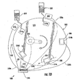
- the turntable 502 cycles through a series of indexed positions or stations, and the stations can be respectively equipped with a supplying apparatus 504, pretreating apparatus 506, installing apparatus 508, post-treating apparatus 510, and receiving apparatus 512.
- the upper surface 513 of the turntable 502 includes or otherwise has associated therewith upwardly open, cavity-like, container-receiving receptacles 514a-514e in a number corresponding to the number of stations around the turntable 502.
- Fig. 10 the upper surface 513 of the turntable 502 includes or otherwise has associated therewith upwardly open, cavity-like, container-receiving receptacles 514a-514e in a number corresponding to the number of stations around the turntable 502.
- the position sensor 522 can be an optical sensor or Hall effect sensor that senses position-indicating marks, magnets or the like (not shown) on the peripheral edge of, or at another acceptable position with respect to, the turntable 502.
- the central controller 516 also respectively communicates, such as via signal communication paths 530a-530e, with the other components of the manufacturing system, typically so that the position of the turntable 502 determines the initiation of the operations of the supplying apparatus 504, pretreating apparatus 506, installing apparatus 508, post-treating apparatus 510, and receiving apparatus 512, as will be discussed in greater detail below.
- the signal communication paths 518, 521, 530a-530e of the manufacturing system 500 can be any type of conventional signal communication paths that would be sufficient. For example, they can be electrical wires that extend all the way between the respective components, or they can be any type of conventional wireless communication systems, such as infrared communication systems, radio frequency communication systems, or the like.
- the receptacle 514e is adjacent the supplying apparatus 504, the receptacle 514a is adjacent the pretreating apparatus 506, the receptacle 514b is adjacent the installing apparatus 508, the receptacle 514c is adjacent the post-treating apparatus 510, and the receptacle 514d is adjacent the receiving apparatus 512.
- the receptacle 514d is adjacent the supplying apparatus 504, the receptacle 514e is adjacent the pretreating apparatus 506, the receptacle 514a is adjacent the installing apparatus 508, the receptacle 514b is adjacent the post-treating apparatus 510, and the receptacle 514c is adjacent the receiving apparatus 512.
- the manufacturing system 500 it might be acceptable for the manufacturing system 500 to include a mechanical drive system, with suitable linkages, gearing and the like, by way of which one or more features of one or more of the apparatuses 504, 506, 508, 510, 512 are driven or at least partially driven by the turntable and/or its motor 520.
- the supplying apparatus 504, pretreating apparatus 506, installing apparatus 508, post-treating apparatus 510, and receiving apparatus 512 each include their own power supply(s), controller(s) and other features needed to carry out their respective functions, with their controllers being respectively connected to the central controller 516 via the signal communication paths 530a-530e for purposes of providing the exemplary coordinated operations that are discussed below.
- the turntable 502 is rotated to the next position, so that the receptacle 514a containing the preformed container 150 ( Fig. 3 ) is adjacent to (e.g., within) the pretreating apparatus 506.
- the optional pretreating apparatus 506 can pretreat the preformed container 150 in the receptacle 514a.
- the pretreating carried out by the pretreating apparatus 506 can be a heat treatment and/or a corona treatment for enhancing the mounting / bonding to be carried out at the next step by the installing apparatus 508.
- the mounting apparatus 544 includes a forming tool 550 for mounting the microwave interactive web 100 to the preformed container 150 in the receptacle 514a, to create the composite container.
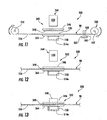
- the installing apparatus is in the configuration shown in Fig. 11 , in which the forming tool 550 and the die plate 546 are each in their retracted configurations.
- the web transporting apparatus 540 includes an upstream reel 552 for carrying an upstream roll from which the composite web 98 is drawn.
- the upstream reel 552 can be a traditional unwind stand with a braking device for maintaining optimal tension in the composite web 98.
- a web splicing apparatus (not shown) may be provided to allow for one expiring roll of composite web 98 to be attached to a new one.
- a pair of driven nip rolls (not shown) or any other suitable mechanism may be used to unwind the composite web 98 from the upstream reel 552 at the desired rate.
- Fig. 11 schematically illustrates the adhesive or heat seal coating being applied at a nip defined between an upper roller 558 and a lower roller 560 that is partially immersed in a bath 562 of the adhesive or heat seal coating.
- the adhesive, heat seal coating or other suitable material may initially be applied to the interior of the preformed container 150 instead of, or in addition to, being initially applied to the composite web 98.
- the cutting apparatus 542 is mounted so that it is aligned with the superpositioned microwave interactive web 100 / preformed container 150 / receptacle 514a in the third position.
- the cutting apparatus 542 includes the overhead, platen-type die plate 546 that is positioned above a fixed, plate-like anvil 564 (e.g., die).
- a fixed, plate-like anvil 564 e.g., die.
- the receptacle 514a and the preformed container 150 that it contains are positioned below the anvil 564, and the microwave interactive web 100 that is to be mounted is positioned between the die plate 546 and the anvil 564 while the die plate is in its retracted configuration shown in Fig. 11 .
- the cutting apparatus 542 can be in many different configurations.
- the fixed anvil 564 that stays proximate to (e.g., aligned with) the die plate 546 could be omitted.
- the turntable 502 ( Fig 10 ) can include anvils that respectively encircle each of the receptacles 514a-514e.
- the face of the die plate 546 can include die rubber projections (not shown), or other suitable means, such as on opposite sides of each of the knives 548, for holding the microwave interactive web 100 that is to be mounted and the remnants 556 stationary against the anvil 564 while the die plate is in its extended configuration and the forming tool 550 is in its retracted configuration, as shown in Fig. 12 .
- the forming tool 550 engages the microwave interactive web 208 and the microwave interactive web 208 is caused to conform to the shape of respective portions of both the forming tool 550 and the preformed container 150. That is, the microwave interactive web 208 is bent so that it defines a cavity that corresponds to the respective portion of the forming tool 550.
- the forming tool 550 extending into the cavity defined by the microwave interactive web 208, and the cavity defined by the microwave interactive web 208 conforming to the shape of the respective portions of the forming tool.
- the forming tool 550 pushes the microwave interactive web 208 through the central opening 568 in the anvil 564 and into the cavity of the preformed container 150 in the receptacle 514a.
- the forming tool 550 of the first embodiment can be characterized as a pusher, since it pushes the microwave interactive web 208 as described above.
- the forming tool 550 When heat is used to activate the adhesive or heat seal coating that bonds the microwave interactive web 208 to the preformed container 150, the forming tool 550 may be heated to a temperature within a range of from about 93.33°C (200°F) to about 204.44°C (400°F), for example from about 107.22°C (225°F) to about 176.67°C (350°F), or from about 121.11°C (250°F) to about 148.89°C (300°F).
- Electric resistance heaters (not shown) or the like can be within or mounted to the forming tool 550 for this purposes, or the forming tool may include internal passageways (not shown) for receiving a flow of heated oil, or the like.
- the receptacles 514a-514e may be associated with one or more features (e.g., cooling fins) that assist with cooling of the composite container 200 after the sealing / bonding process to minimize warping and/or buckling of the container.
- Any suitable cooling elements or features may be used for cooling one or more of the receptacles 514a-514e or the composite containers within the receptacles 514a-514e.
- the cooling can be provided by features that circulate a cooling medium, such as water or air, or any other type of cooling or refrigeration system that can provide the desired heat transfer. In some situations, this heating and cooling may not be required.
- the adherence between the microwave interactive web 208 and the preformed container 150 is discussed as being at least partially facilitated by an adhesive or heat seal coating activated by heat and/or pressure.
- an adhesive or heat seal coating activated by heat and/or pressure.
- One such coating is a polyester heat seal coating that is commercially available from Coim (United Kingdom) under the trade name EX-8056 HEAT SEAL.
- the adhesive or heat seal coating may comprises a thermosetting polymeric material, a thermoplastic polymeric material, or any combination thereof. Such coatings may be applied in any amount needed to achieve the desired adhesion between the materials. More generally, the adherence between the microwave interactive web 208 and the preformed container 150 can be provided using adhesive bonding, thermal bonding, ultrasonic bonding, or any other suitable technique.
- the forming tool 550 remains in its extended configuration for a duration sufficient to activate the adhesive or heat seal coating and join the microwave interactive web 208 to the preformed container 150 in the receptacle 514a, thereby forming the resulting composite container 200. Thereafter, both the forming tool 550 and the die plate 546 are moved to their retracted positions shown in Fig. 11 , so that: 1) the turntable 502 ( Fig. 10 ) can be rotated so that the preformed container 150 that is being carried by the next receptacle 514b ( Fig.
- the web transporting apparatus 540 ( Fig. 11 ) can resume its above-described transporting functions, so that the next microwave interactive web 208 in the composite web 98 can be moved downstream (along the path of travel established by the web transporting apparatus) to be superposed with the preformed container 150 that is being carried by the receptacle 514b, at which time the transporting function provided by the transporting apparatus temporarily ceases.
- the incremental transporting operations of the turntable 502 and web transporting apparatus 540 1) occur while both the forming tool 550 and the die plate 546 are in their retracted positions shown in Fig. 11 ; 2 ) do not occur while the die plate and/or the forming tool are in their extended configurations respectively shown in Figs. 12 and 13 ; and 3 ) resume when (e.g., in response to) both the forming tool and the die plate returning to their retracted positions shown in Fig. 11 .
- the cutting apparatus 542 ( Figs. 11-13 ) can be in many different configurations.
- the reciprocating die plate 546 with the knives 548 may be omitted in an alternative embodiment. Omitting the reciprocating die plate 546 can result in the incremental transporting operations of the turntable 502 and web transporting apparatus 540: 1) occurring while the forming tool 550 is in its retracted position; 2) not occurring while the forming tool is in its extended configuration; and resuming when (e.g., in response to) the forming tool returning to its retracted position. That is, there can be variations to the aspects of the present invention that relate to the various simultaneous and sequential steps of the manufacturing system 500.
- Fig. 15 is a schematic, isolated, top perspective view of the generally plate-like anvil 564 of the cutting apparatus
- Fig. 16 is a schematic, isolated, bottom perspective view of the die plate 546 of the cutting apparatus.
- the die plate 546 carries one or more knives 548 ( Figs. 11-13 ) or other cutting devices (e.g., steel rules that can be generally characterized as being long razor plates) for cutting the microwave interactive web 208 from the composite web 98.
- the knives 548 are not shown in Fig.
- the anvil 564 includes a central opening 568 through which the forming tool 550 extends when the forming tool is in its extended configuration shown in Fig. 13 .
- the die plate 546 includes a central opening 566 through which the forming tool 550 extends when the forming tool is in its extended configuration.
- the anvil 564 defines a recess 570 that extends around its central opening 568, and the die plate 546 includes a raised area 572 that extends around its central opening 566.
- Fig. 17 is a top perspective view of the anvil 564 of Fig. 15 and the die plate 546 of Fig. 16 mated with one another in the manner described immediately above.
- one or both of the die plate 546 and the anvil 564 can include features for initiating or otherwise at least partially controlling the pleats / pleating.
- these features can be notches, groves, protrusions or any other suitable features.
- female pleating plates 574 e.g., pleating dies
- male pleating plates 576 e.g., pleating dies
- the female pleating plates 574 can be mounted to the anvil 564, and male pleating plates 576 can be mounted to the die plate 546.
- the pleating plates 574, 576 extend at least partially around the respective central openings 566, 568 and they may extend completely around the central openings (e.g., when the containers are round bowls).
- Each of the female pleating plates 574 includes elongate recesses (e.g., indentions).
- Each of the male pleating plates 576 includes elongate protrusions. Protrusions of the male pleating plates 576 are for being respectively at least partially received in, or for being proximate, recesses of the female pleating plates 574.
- microwave interactive web 208 As the microwave interactive web 208 is being forced into the preformed container 150, respective portions of the microwave interactive web are positioned between, and slide between, the respectively mated female and male pleating plates 574, 576 in a manner that seeks to optimally control the pleating of the microwave interactive web.
- the female and male pleating plates 574, 576 are respectively mated with respect to one another while the anvil 564 and die plate 546 are mated together as shown in Fig. 17 .
- the knives 548 are omitted from the die plate 546, and the microwave interactive web 208 is cut, tom or otherwise separated from the composite web 98 by way of one or more other mechanisms.
- the microwave interactive web 208 is cut from the composite web 98 and the remnants 556 by a laser beam 580 that is schematically illustrated by a dashed line in Fig. 18 .
- the laser 582 is used after the microwave interactive web 208 has been mounted to the preformed container 150 and at least the forming tool 550 ( Figs. 11-13 ) has been returned to its retracted configuration.
- the cutting of the microwave interactive web 208 from the composite web 98 and the remnants 556 can be carried out using one or more "through-cut" reciprocating cutting blades (not shown) (e.g., with jagged teeth).
- the reciprocating cutter could be a movably mounted jig saw, or the like, where the movement and other operations of the saw are controlled by a computer controller (e.g., a CNC cutting machine that uses a cutting blade made of metal or other suitable material).
- a computer controller e.g., a CNC cutting machine that uses a cutting blade made of metal or other suitable material.
- the turntable 502 Fig.
- the microwave interactive webs 208 may be initially connected to the rest of composite web 98 by tear lines (not shown) (e.g., formed by perforations or spaced apart slits), such that the microwave interactive webs are torn from the composite web when respectively forced into the preformed containers 150, so that cutting blades, lasers and the like for cutting the microwave interactive webs from the composite web may be omitted from the manufacturing system 500.
- tear lines not shown
- the microwave interactive webs 208 may be initially connected to the rest of composite web 98 by tear lines (not shown) (e.g., formed by perforations or spaced apart slits), such that the microwave interactive webs are torn from the composite web when respectively forced into the preformed containers 150, so that cutting blades, lasers and the like for cutting the microwave interactive webs from the composite web may be omitted from the manufacturing system 500.
- the mounting apparatus 544 could be a "stand-alone" unit as generally shown in Fig. 19 . That is, although the manufacturing system 500 ( Fig. 10 ) of the first embodiment is described herein primarily in the context of a machine in which the operations of the various components are coordinated so as to continually and serially form the composite containers, alternatively the respective components of the manufacturing system 500 may not be integrated so that many of the steps of forming the composite containers are carried out more separately from one another in a batch-type manner.
- the receptacle 514a could be mounted to the frame 602 rather than being carried by the turntable 502 ( Fig. 10 ).
- the forming tool 550 by using a compliant material to form the forming tool 550, it is possible to use a forming tool that initially has greater dimensions than those of the interior of the preformed container 150, thereby further improving contact between the microwave interactive web 208 and the preformed container 150.
- the remaining portions of the forming tool 550 may be made from a relatively light-weight, conductive material, such as aluminum or any other suitable material.
- the lower face 614 of the forming tool 550 and/or the base 620 of the receptacles 514a-514e may include a protrusion (e.g., an arcuate protrusion) or otherwise be crowned, or the like, to create an initial point of contact between the microwave interactive web 208 and the preformed container 150, as shown schematically in Fig. 23 .
- Fig. 23 is a schematic, cross-sectional view showing how the forming tool 550 and the representative receptacle 514a can be shaped, with the cross-section being taken vertically through the center of the forming tool and the representative receptacle, and only the cross-section being shown.
- the receptacle 514a can move to accommodate for a wide variety of variations that might occur, such as due to varying tolerances that may exist in a wide variety of the features of the present invention.
- the turntable 502 is rotated to the next position, so that the receptacle 514a containing the composite container 200 is adjacent to the post-treating apparatus 510.
- the optional post-treating apparatus 510 can post-treat the composite container 200 in the receptacle 514a.
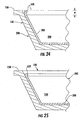
- the flap-like feature 630 can extend around the entire periphery of the microwave interactive web 208.
- the flap-like feature 630 may not be formed, or it may only be formed at one or more segments of the periphery of the microwave interactive web 208 that are spaced apart from one another.
- the portion of the microwave interactive web 208 that includes any microwave interactive material is securely adhered to the previously formed container 150 such that the flap-like feature 630 consist solely of the polymer film substrate 112. In these situations, the bead 632 will be formed solely from the polymer film substrate 112.
- the flap-like feature 630 may include a portion of this or another type of susceptor.
- the post-treating apparatus 510 may be at least generally in the form of a microwave oven, or the like, so that the susceptor-like flap-like feature 630 shrinks to form / transforms into the bead 632 in response to being exposed to a short application of microwave energy.
- the heating of the flap-like feature 630 that transforms it into the bead 632 typically occurs prior to loading the composite container 200 with contents such as food (not shown).
- Fig. 26 is a schematic top plan view of a multi-compartment composite container 640 in accordance with a version of a second exemplary embodiment of the present invention.
- the second embodiment is like the first embodiment, except for variations noted and variations that will be apparent to those of ordinary skill in the art.
- the multi-compartment composite container 640 is like the above-discussed composite containers, except that it includes an upright barrier 642 (e.g., a middle wall), or the like, so that the multi-compartment composite container includes two cavities that are side by side.
- a first cavity 644 of the two cavities has mounted therein a microwave interactive web 208 of the type discussed above with reference to Figs.
- any of the above-discussed microwave interactive webs can be placed over or otherwise associated with the face of the forming tool 600 while the partial vacuum is provided to the face of the forming tool.
- Fig. 30 shows the microwave interactive web 208 drawn to the face of the forming tool by the partial vacuum supplied to the face of the forming tool, so that the microwave interactive web is conformed to the shape of the face of the forming tool to create a three-dimensional microwave interactive structure 666.
- Fig. 31 is a schematic, isolated perspective view of the three-dimensional microwave interactive structure 666 of Fig. 30 . As apparent from Figs.
- a composite container 200' ( Fig. 34 ) that is like the composite container 200 of Fig. 4 , except for variations noted and variations that will be apparent to those of ordinary skill in the art.
- the composite container 200' is formed through the use of a modified microwave interactive web 208' and three-dimensional microwave interactive structure 666' that are respectively like the above-discussed microwave interactive web 208 and three-dimensional microwave interactive structure 666 of the first version of the third embodiment except for having slits or other physical apertures 674 extending completely therethrough, as shown in Fig. 32 .
- a polymer sheet 676 for example, a sheet of polyester or coextruded polyethylene terephthalate, is placed over the microwave interactive web 208' / three-dimensional microwave interactive structure 666'.
- the polymer sheet 676 will be heated to a sufficient degree (or otherwise processed) so that it is sufficiently flexible so that the partial vacuum draws the polymer sheet toward the three-dimensional microwave interactive structure 666' and forms the polymer sheet 676 into the desired shape.
- the polymer sheet 676 and the three-dimensional microwave interactive structure 666' are joined with the heal seal coating or adhesive, or by any other acceptable means, to form the composite container 200' schematically shown in Fig. 34 .
Landscapes
- Engineering & Computer Science (AREA)
- Mechanical Engineering (AREA)
- Physics & Mathematics (AREA)
- Life Sciences & Earth Sciences (AREA)
- Food Science & Technology (AREA)
- Electromagnetism (AREA)
- Optics & Photonics (AREA)
- Plasma & Fusion (AREA)
- Cookers (AREA)
- Package Specialized In Special Use (AREA)
- Packages (AREA)
- Details Of Rigid Or Semi-Rigid Containers (AREA)
Abstract
Description
- The present invention relates to a construct of the generic type defined in the preamble of claim 1 reflecting the state of the art disclosed e.g. in
WO 03/043474 A1 WO 03/043474 A1 - Microwave ovens have become a principle form of heating food in a rapid and effective manner. A variety of containers for heating, browning and/or crisping food items in microwave ovens are know. For example, in a conventional manufacturing process, a microwave interactive web is positioned over a flat paperboard blank and laminated to the blank, and then the blank with the attached microwave interactive web is erected into a package. Such packages have been successfully commercialized. Nonetheless, there is a continuing need for containers that provide a new balance of properties and for improved methods of foaming such containers.
- The above-mentioned
WO 03/043474 A1 -
WO 03/078012 A1 - The present invention aims at improving the microwave interactive properties of constructs of the generic type.
- The object set out above is achieved by a construct as defined in claim 1 and by a method of making a construct as defined in claim 14, respectively.
- One aspect of the present invention is the provision of a container that includes a microwave interactive web at least partially overlying and joined to a three-dimensional support, wherein the three-dimensional support may be formed prior to having the microwave interactive web mounted thereto. The three-dimensional support may be a preformed container that is sufficiently rigid and dimensionally stable for use in containing food. Accordingly and in accordance with one aspect of the present invention, the microwave interactive web is mounted to the preformed container so that the preformed container with the microwave interactive web can be used to contain a food item being heated in a microwave oven. The microwave energy interactive web typically includes a microwave interactive material, for example a metal, supported on a substrate, typically a polymer film. The microwave interactive material includes one or more features that interact with microwave energy to enhance or reduce the effects of the microwave energy on the food. For example, the feature may shield the food item, direct microwave energy to particular areas of the food item, and/or promote browning and/or crisping of the surface of the food item.
- According to one aspect of the present invention, the preformed container may be formed of polymeric material and/or paperboard, or the like. More specifically, the preformed container can be a polymeric tray or bowl formed by injection molding or vacuum forming (e.g., vacuum thermal-forming), or a tray or bowl that includes paperboard panels (e.g., walls) that are held together by an injection-molded frame. In one particular example, the container may consist essentially of polymeric material, or even more specifically it may consist solely of polymeric material. Other types of preformed containers are also within the scope of the present invention.
- In accordance with one aspect of the present invention, a construct includes a three-dimensional support (e.g., container) and a microwave interactive web mounted to the container, with the web including a plurality of pleats. The pleats may be positioned in and extend along an interior corner of the container. The interior corner of the container may be at least partially defined by a substantially smooth surface of the container, with the pleats extend across the substantially smooth surface.
- The container may include a base and a plurality of side walls. The side walls may extend upwardly from the base and at least partially around a cavity of the container. The web may be positioned in the cavity so that it at least partially covers the base and/or at least one of the side walls. More specifically, the microwave interactive material of the web may at least partially cover the base and/or one or more of the side walls. The microwave interactive material of the web may extend at least partially around, or substantially all the way around, the cavity of the container. The web may include a peripheral edge that comprises a bead, and the bead may extend substantially all the way around the cavity of the container.
- The container may include a plurality of compartments, with the web being in a first of the compartments. There may be a second microwave interactive web mounted in a second compartment of the container. The first and second webs may be distinct from one another.
- One aspect of the present invention relates to a method of making a construct that includes microwave interactive material. The method may include providing a preformed container, and then mounting a microwave interactive web to the preformed container. In accordance with one aspect, the mounting of the web to the preformed container comprises mounting the web within the cavity of the preformed container.
- The method may include cutting the web with a laser. This cutting may occur after the mounting of the web within the cavity of the container. In accordance with one aspect, the cutting of the web with the laser comprises directing a laser beam through an opening of the container.
- In accordance with one aspect of the present invention, a method of making a container includes reconfiguring a microwave interactive web and mounting the web to a three-dimensional support (e.g., a preformed container) while the web extends at least partially around and at least partially defines a cavity. The reconfiguring of the web may include forming pleats in the web.
- The method may further include heating at least a flap-like edge portion of the web to transform the flap-like edge portion of the web into a bead. This heating typically occurs after the mounting and prior to placing food in the container.
- Other aspects and advantages of the present invention will become apparent from the following.
- Having described some aspects of the invention in general terms, reference will now be made to the accompanying drawings that illustrate exemplary embodiments of the present invention and are not necessarily drawn to scale.
-
Fig. 1 is a schematic plan view of a piece of a composite web that includes a series of microwave interactive webs that can be cut from the composite web and be respectively mounted to structures such as, but not limited to, preformed containers, in accordance with exemplary embodiments of the present invention. -
Fig. 2 is a perspective view of an example of a microwave interactive web of the composite web ofFig. 1 . -
Fig. 3 is a perspective view of a conventional, polymeric, preformed container to which the microwave interactive web ofFig. 2 can be mounted, in accordance with a first exemplary embodiment of the present invention. -
Fig. 4 is a schematic, perspective view of a composite container, namely a microwave interactive web mounted to the preformed container ofFig. 3 , in accordance with a first version of the first exemplary embodiment of the present invention. -
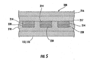
Fig. 5 is a schematic cross-sectional view of a portion of the composite container ofFig. 4 , with the cross-section taken along line 5-5 ofFig. 4 , and only the cross-sectiori being shown. -
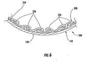
Fig. 6 is a schematic, generally horizontal cross-sectional view taken substantially along line 6-6 ofFig. 4 , for illustrating pleats of the microwave interactive web, and only the cross-section is shown. -
Fig. 7 is a cross-sectional view like that ofFig 5 , except thatFig. 7 is a cross section of a different composite container, namely a composite container that is like the tray ofFig. 4 except for including an additional layer of microwave interactive material, in accordance with a second version of the first exemplary embodiment of the present invention. -
Fig. 8 is a perspective view of a composite container, namely a microwave interactive web mounted to the preformed container ofFig. 3 , in accordance with a third version of the first exemplary embodiment of the present invention. -
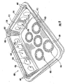
Fig. 9 is a perspective view of a composite container, namely a microwave interactive web mounted to the preformed container ofFig. 3 , in accordance with a fourth version of the first exemplary embodiment of the present invention. -
Fig. 10 is a schematic, generally top plan view of portions of a manufacturing system for combining a microwave interactive web to a preformed container to create a composite container, in accordance with the first exemplary embodiment of the present invention. -
Fig. 11 is a schematic, side elevation view of an installing apparatus of the manufacturing system ofFig. 10 , with a receptacle of a turntable of the manufacturing system being positioned below the installing apparatus, and a forming tool and die plate of the installing apparatus being in a retracted configuration. -
Fig. 12 is likeFig. 11 , except that reels and associated rolls of material are not shown, and the die plate is in an extended configuration. -
Fig. 13 is likeFig. 12 , except that the forming tool is also in an extended configuration. -
Fig. 14 is a schematic, isolated, perspective view of the microwave interactive web of the composite container ofFig. 4 in a substantially flat configuration.Fig. 14 is illustrative of how this microwave interactive web would appear, in isolation, while in the installing apparatus with the installing apparatus being in the configuration shown inFig. 12 . -
Fig. 15 is a schematic, isolated, top perspective view of an anvil of the installing apparatus ofFig. 10 . -
Fig. 16 is a schematic, isolated, bottom perspective view of a die plate of the installing apparatus ofFig. 10 . -
Fig. 17 is a top perspective view of the anvil ofFig. 15 and the die plate ofFig. 16 mated with one another while the die plate is in the extended configuration shown inFigs. 12 and 13 . -
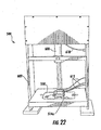
Fig. 18 schematically illustrates a computerized numerical control laser cutting machine cutting the composite web and remnants of the composite web from the microwave interactive web that has already been mounted to a preformed container that is in a representative receptacle of the turntable, with only a vertical cross-section of some of the features being shown. -
Fig. 19 is a schematic perspective view of a mounting apparatus of the installing apparatus ofFigs. 10-13 , with the forming tool of the mounting apparatus in its retracted configuration and positioned above a representative one of the turntable's receptacles. -
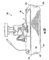
Fig. 20 is a schematic perspective view of a portion of the mounting apparatus, showing the forming tool in greater detail. -
Fig. 21 is a schematic perspective view of a portion of the forming tool positioned above the representative receptacle. -
Fig. 22 is a schematic perspective view of a portion of the mounting apparatus showing the forming tool in its extended configuration, in which it extends into the representative receptacle. -
Fig. 23 is a schematic cross-sectional view showing how the forming tool and the representative receptacle can be shaped, with the cross-section being taken vertically through the center of the forming tool and the representative receptacle, and only the cross-section being shown. -
Fig. 24 is a schematic, vertical cross-sectional view of a portion of a composite container, showing how a peripheral edge of the microwave interactive web of the composite container may be a flap-like feature that is not adhered to the preformed container. -
Fig. 25 is likeFig. 24 , except that the flap-like feature has been transformed into a bead, such as through a post-treatment heating process. -
Fig. 26 is a schematic, top plan view of a multi-compartment composite container in accordance with a version of a second embodiment of the present invention. -
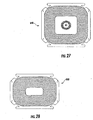
Fig. 27 is a schematic, isolated top plan view of a microwave interactive web in a flat configuration, wherein this microwave interactive web replaces one of the microwave interactive webs shown inFig. 26 . -
Fig. 28 is a schematic, isolated top plan view of a microwave interactive web in a flat configuration, wherein this microwave interactive web replaces one of the microwave interactive webs shown inFig. 26 . -
Fig. 29 is a schematic, partially cross-sectional view of a forming tool associated with a vacuum pump. -
Fig. 30 is likeFig. 29 , except that a microwave interactive web is shown drawn to the face of the forming tool, so that the microwave interactive web is conformed to the shape of the face of the forming tool to create a three-dimensional microwave interactive structure. -
Fig. 31 is a schematic, isolated perspective view of the three-dimensional microwave interactive structure ofFig. 30 . -
Fig. 32 is likeFig. 30 , except that the three-dimensional microwave interactive structure drawn to the face of the forming tool includes holes. -
Fig. 33 is likeFig. 32 , except that it further illustrates a polymer sheet that is schematically shown as being drawn toward the three-dimensional microwave interactive structure. -
Fig. 34 is likeFig. 33 , except for showing that the polymer sheet has been joined to the three-dimensional microwave interactive structure to create a composite container. - Referring now in greater detail to the drawings, in which like numerals refer to like parts throughout the several views,
Fig. 1 is a schematic plan view of a piece of acomposite web 98 that includes a series of microwave energy interactive webs 100 (or simply "microwave interactive webs") that can be cut from thecomposite web 98 and be respectively mounted to supports, in accordance with exemplary embodiments of the present invention.Fig. 2 is a perspective view of an acceptable example of a microwaveinteractive web 100 of thecomposite web 98 ofFig. 1 . The microwave interactioninteractive web 100 ofFig. 2 can be representative of each of the microwaveinteractive webs 100 of thecomposite web 98. As shown inFig. 2 , the microwaveinteractive web 100 is substantially flat. - Referring to
Fig. 2 in greater detail and in accordance with one example of a first exemplary embodiment of the present invention, the microwaveinteractive web 100 can be mounted to a conventional preformed container 150 (Fig. 3 ). The microwaveinteractive web 100 shown inFig. 2 includes a first microwaveinteractive element 102 comprising a metal foil band including somewhat roundedcorners 104 andobround apertures 106 in a spaced apart configuration. In accordance with the first embodiment, as used herein, the term "obround" refers to a shape substantially consisting of two semicircles connected by parallel lines tangent to their endpoints. The microwaveinteractive web 100 also includes a second microwaveinteractive element 108 comprising microwaveinteractive foil segments 110 arranged in clusters in a lattice-like configuration. Only a few of thefoil segments 110 are identified by their reference numeral inFig. 2 . The first microwaveinteractive element 102 is spaced from and forms a border around the second microwaveinteractive element 108. The first microwaveinteractive element 102 and the second microwaveinteractive element 108 are supported on apolymer film substrate 112. Referring back toFig. 1 , thepolymer film substrate 112 extends between the opposite ends of thecomposite web 98. - Although a particular microwave
interactive web 100 with first and second microwaveinteractive elements Figs. 1 and2 , each of the exemplary embodiments of the present invention can incorporate a wide variety of microwave interactive webs (e.g., the microwaveinteractive web 100 ofFig. 2 ) that include features that alter the effect of microwave energy during heating or cooking of a food item. For example, the microwave interactive webs of the exemplary embodiments may be formed at least partially from one or more microwave energy interactive elements (hereinafter referred to as "microwave interactive elements") (e.g., see the microwaveinteractive elements Fig. 2 ) that promote browning and/or crisping of a particular area of the food item, shield a particular area of the food item from microwave energy to prevent overcooking thereof, or transmit microwave energy towards or away from a particular area of the food item. Each microwave interactive element comprises one or more microwave energy interactive materials or segments arranged in a particular configuration to absorb microwave energy, transmit microwave energy, reflect microwave energy, or direct microwave energy, as needed or desired for a particular microwave heating container and food item. The microwave interactive element may be supported on a microwave inactive or transparent substrate (e.g., see thepolymer film substrate 112 ofFigs. 1 and2 ) for ease of handling and/or to prevent contact between the microwave interactive material and the food item. As a matter of convenience and not limitation, and although it is understood that a microwave interactive element supported on a microwave transparent substrate includes both microwave interactive and microwave inactive elements or components, such constructs are referred to herein as "microwave interactive webs". - The microwave energy interactive material may be an electroconductive or semiconductive material, for example, a metal or a metal alloy provided as a metal foil; a vacuum deposited metal or metal alloy; or a metallic ink, an organic ink, an inorganic ink, a metallic paste, an organic paste, an inorganic paste, or any combination thereof. Examples of metals and metal alloys that may be suitable for use with the present invention include, but are not limited to, aluminum, chromium, copper, inconel alloys (nickel-chromium-molybdenum alloy with niobium), iron, magnesium, nickel, stainless steel, tin, titanium, tungsten, and any combination or alloy thereof.
- Alternatively, the microwave energy interactive material may comprise a metal oxide. Examples of metal oxides that may be suitable for use with the present invention include, but are not limited to, oxides of aluminum, iron, and tin, used in conjunction with an electrically conductive material where needed. Another example of a metal oxide that may be suitable for use with the present invention is indium tin oxide (ITO). ITO can be used as a microwave energy interactive material to provide a heating effect, a shielding effect, a browning and/or crisping effect, or a combination thereof. For example, to form a susceptor, ITO may be sputtered onto a clear polymer film. The sputtering process typically occurs at a lower temperature than the evaporative deposition process used for metal deposition. ITO has a more uniform crystal structure and, therefore, is clear at most coating thicknesses. Additionally, ITO can be used for either heating or field management effects. ITO also may have fewer defects than metals, thereby making thick coatings of ITO more suitable for field management than thick coatings of metals, such as aluminum.
- Alternatively, the microwave energy interactive material may comprise a suitable electroconductive, semiconductive, or non-conductive artificial dielectric or ferroelectric. Artificial dielectrics comprise conductive, subdivided material in a polymeric or other suitable matrix or binder, and may include flakes of an electroconductive metal, for example, aluminum.
- In one example, the microwave interactive element may comprise a thin layer of microwave interactive material that tends to absorb microwave energy, thereby generating heat at the interface with a food item. Such elements often are used to promote browning and/or crisping of the surface of a food item (sometimes referred to as a "browning and/or crisping element"). When supported on a film or other substrate, such an element may be referred to as a "susceptor" or "susceptor film".
- As another example, the microwave interactive element may comprise a foil having a thickness sufficient to shield one or more selected portions of the food item from microwave energy (sometimes refereed to as a "shielding element"). Such shielding elements may be used where the food item is prone to scorching or drying out during heating.
- The shielding element may be formed from various materials and may have various configurations, depending on the particular application for which the shielding element is used. Typically, the shielding element is formed from a conductive, reflective metal or metal alloy, for example, aluminum, copper, or stainless steel. The shielding element generally may have a thickness of from about 7.239 µm (0,000285 inches) to about 1.27 mm (0.05 inches).In one aspect, the shielding element has a thickness of from about 7.62 µm (0,0003 inches) to about 0.762 mm (0.03 inches). In another aspect, the shielding element has a thickness of from about 8.89 µm (0.00035 inches) to about 0.508 mm (0.020 inches), for example 0.4064 mm (0.016 inches).
- As still another example, the microwave interactive element may comprise a segmented fail, such as, but not limited to, those described in
U.S. Patent Nos. 6,204,492 .6,433,322 ,f,552,3I5 6,677,563 . Although segmented foils are not continuous, appropriately spaced groupings of such segments often act as a transmitting element to direct microwave energy to specific areas of the food item. Such foils also may be used in combination with browning and/or crisping elements, for example, susceptors. - Any of the numerous microwave interactive elements described herein or contemplated hereby may be substantially continuous, that is, without substantial breaks or interruptions, or may be discontinuous, for example, by including one or more breaks or apertures that transmit microwave energy therethrough. The breaks or apertures may be sized and positioned to heat particular areas of the food item selectively. The number, shape, size, and positioning of such breaks or apertures may vary for a particular application depending on type of container being formed, the food item to be heated therein or thereon, the desired degree of shielding, browning, and/or crisping, whether direct exposure to microwave energy is needed or desired to attain uniform heating of the food item, the need for regulating the change in temperature of the food item through direct heating, and whether and to what extent there is a need for venting.
- The aperture may be a physical aperture or void in the material used to form the container, or may be a non-physical "aperture". A non-physical aperture may be a portion of the container that is microwave energy inactive by deactivation, removal, or otherwise, or one that is otherwise transparent to microwave energy. Thus, for example, where a microwave energy interactive material is used to form at least a portion of the container, the aperture may be a portion of the container formed without a microwave energy active material or, alternatively, may be a portion of the container formed with a microwave energy active material that has been deactivated or removed. While both physical and non-physical apertures allow the food item to be heated directly by the microwave energy, a physical aperture may also provide a venting function to allow steam or other vapors to escape from the interior of the container.
- As stated above, any of the above elements and numerous others contemplated hereby may be supported on a substrate, The substrate typically comprises an electrical insulator, for example, a polymer film. The thickness of the film may typically be from about 8.89 µm (35 gauge) to about 254 µm (10 mil). In one aspect, the thickness of the film is from about 10.16 µm (40 gauge) to about 20.32 µm (80 gauge). In another aspect, the thickness of the film is from about 11.43 to about 12.7 µm (45 to about 50 gauge). In still another aspect, the thickness of the film is about 12.192 µm (48 gauge). Examples of polymer films that may be suitable include, but are not limited to, polyolefins, polyesters, polyamides, polyimides, polysulfones, polyether ketones, cellophanes, or any combination thereof. Other non conducting substrate materials such as paper and paper laminates, metal oxides, silicates, cellulosics, or any combination thereof, also may be used.
- In one aspect, the polymer film may comprise polyethylene terephthalate. Examples of polyethylene terephthalate films that may be suitable for use as the substrate include, but are not limited to, MELINEX®, commercially available from DuPont Teijan Films (Hopewell, Virginia), and SKYROL, commercially available from SKC, Inc. (Covington, Georgia). Polyethylene terephthalate films arc used in commercially available susceptors, for example, the QWIKWAVE® Focus susceptor and the MICRORITE® susceptor, both available from Graphic Packaging International, Inc. (Marietta, Georgie).
- In another aspect, the polymer film may be selected to provide a water barrier, oxygen barrier, or a combination thereof. Such barrier film layers may be formed from a polymer film having barrier properties or from any other barrier layer or coating as desired. Suitable polymer films may include, but are not limited to, ethylene vinyl alcohol, barrier nylon, polyvinylidene chloride, barrier fluoropolymer,
nylon 6,nylon coextruded nylon 6/BVOH/nylon 6, silicon oxide coated film, or any combination thereof. One example of a barrier film that may be suitable for use with the present invention is CAPRAN®EMBLEM 1200M nylon 6, commercially available from Honeywell International (Pottsville, Pennsylvania). Another example of a barrier film that may be suitable is CAPRAN® OXYSHIELD OBS monoaxially orientedcoextruded nylon 6/ethylene vinyl alcohol (EVOH)/nylon 6, also commercially available from Honeywell International. Yet another example of a barrier film that may be suitable for use with the present invention is DARTEK® N-201nylon - Still other barrier films include silicon oxide coated films, such as those available from Sheldahl Films (Northfield, Minnesota). Thus, in one example, a susceptor may have a structure including a film, for example, polyethylene terephthalate, with a layer of silicon oxide coated onto the film, and ITO or other material deposited over the silicon oxide. If needed or desired, additional, layers or coatings may be provided to shield the individual layers from damage during processing.
- The barrier film may have an oxygen transmission rate (OTR) as measured using ASTM D3985 of less than about 20 cm3/m2/day. In one aspect, the barrier film has an OTR of less than about 10 cm3/m2/day. In another aspect, the barrier film has an OTR of less than about 1 cm3/m2/day. In still another aspect, the barrier film has an OTR of less than about 0.5cm3/m2/day. In yet another aspect, the barrier film has an OTR of less than about 0.1 cm3/m2/day.
- The barrier film may have a water vapor transmission rate (WVTR) as measuring using ASTM F1249 of less than about 100 g/m2/day. In one aspect, the barrier film has a WVTR of less than about 50 g/m2/day. In another aspect, the barrier film has a WVTR of less than about 15 g/m2/day. In yet another aspect, the barrier film has a WVTR of less than about 1 g/m2/day. In still another aspect, the barrier film has a WVTR of less than about 0.1 g/m2/day. In a still further aspect, the barrier film has a WVTR of less than about 0.05 g/m2/day.
- The microwave energy interactive material may be applied to the substrate (e.g.,
polymer film substrate 112 ofFigs. 1 and2 ) in any suitable manner, and in some instances, the microwave energy interactive material is printed on, extruded onto, sputtered onto, evaporated on, or laminated to the substrate. The microwave energy interactive material may be applied to the substrate in any pattern, and using any technique, to achieve the desired heating effect of the food item. - For example, the microwave energy interactive material may be provided as a continuous or discontinuous layer or coating including circles, loops, hexagons, islands, squares, rectangles, octagons, and so forth. Examples of various patterns and methods that may be suitable for use with the present invention are provided in
U.S. Patent Nos. 6,765,182 ;6,717,121 ;6,677,563 ;6,552,315 ;6,455,827 ;6,433,322 ;6,414,290 ;6,251,451 ;6,204,492 ;6,150,646 ;6,114,679 ;5,800,724 ;5,759,422 ;5,672,407 ;5,628,921 ;5,519,195 ;5,424,517 ;5,410,135 ;5,354,973 ;5,340,436 ;5,266,386 ;5,260,537 ;5221,419 ;5,213,902 ;5,117,078 ;5,039,364 ;4,963,424 ;4,936,935 ;4,890,439 ;4,775,771 ;4,865,921 ; andRe. 34,683 . Although particular examples of patterns of microwave energy interactive material are shown and described herein, it should be understood that other patterns of microwave energy interactive material are contemplated by the present invention. - In the exemplary microwave
interactive web 100 schematically shown inFig. 2 , the microwaveinteractive elements polymer film substrate 112. However, in some instances, it may be desirable to provide a microwave interactive web having a uniform color and/or appearance. Such a microwave interactive web may be more aesthetically pleasing to a consumer, particularly when the consumer is accustomed to containers having certain visual attributes, for example, a solid color, a particular pattern, and so on. Thus, for example, the present invention contemplates using a silver or grey toned adhesive to join the microwave interactive elements to the substrate, using a silver or grey toned substrate to mask the presence of the silver or grey toned microwave interactive elements, using a dark toned substrate, for example, a black toned substrate, to conceal the presence of the silver or grey toned microwave interactive elements, overprinting the metallized side of the microwave interactive web with a silver or grey toned ink to obscure the color variation, printing the non-metallized side of the microwave interactive web with a silver or grey ink or other concealing color in a suitable pattern or as a solid color layer to mask or conceal the presence of the microwave interactive elements, or any other suitable technique or combination thereof. - In accordance with the exemplary embodiments of the present invention and very generally described, the microwave interactive element or microwave interactive web (e.g., the microwave
interactive web 100 ofFig. 2 ) is mounted to a three-dimensional support (e.g., the preformedcontainer 150 ofFig. 3 ) that is typically dimensionally stable and microwave energy transparent. Various materials may be used to form the support (e.g., the preformedcontainer 150 ofFig. 3 ). The support, like the microwave interactive web, will typically be constructed from materials that are resistant to softening, scorching, combusting, or degrading at typical microwave oven heating temperatures, for example, at about 121.11°C (250°F). These items may also be constructed from materials that are resistant to softening, scorching, combusting, or degrading at typical conventional oven heating temperatures, for example, from about 232.22°C (450°F) to about 287.78°C (550°F). For example, the support may be formed at least partially from a polymer or polymeric material. As used herein the term "polymer" or "polymeric material" includes, but is not limited to, homopolymers. copolymers, such as for example, block, graft, random, and alternating copolymers, terpolymers, etc. and blends and modifications thereof. Furthermore, unless otherwise specifically limited, the term "polymer" shall include all possible geometrical configurations of the molecule. These configurations include, but are not limited to isotactic, syndiotactic, and random symmetries. One polymer that may be suitable for use with the present invention is polycarbonate. Other examples of polymers that may be suitable for use with the present invention include, but are not limited to, polyolefins, e.g. polyethylene, polypropylene, polybutylone, and copolymers thereof; polytetrafluoroethylene; polyesters, e.g. polyethylene terephthalate, e.g., coextruded polyethylene terephthalate; vinyl polymers, e.g., polyvinyl chloride, polyvinyl alcohol, ethylene vinyl alcohol, polyvinylidene chloride, polyvinyl acetate, polyvinyl chloride acetate, polyvinyl butyral; acrylic resins, e.g. polyacrylate, polymethylacrylate, and polymethylmethacrylate; polyamides, e.g.,nylon - Alternatively, all or a portion of the support (e.g., the preformed
container 150 ofFig. 3 ) may be formed at least partially from a paper or paperboard material, which may be cut into a blank prior to use in the container. In one aspect, the support is formed from paper generally having a basis weight of from about 6.804 kg to about 27.216 kg/ream (i.e., kg/278.709 m2) (15 to about 60 lbs/ream (i.e., lbs / 3,000 ft2)), for example, from about 9.072 to about 18.144 kg/ream (20 to about 40 lbs/ream). In one particular example, the paper has a basis weight of about 11.34 kg/ream (25 lbs/ream). In another aspect, the support is formed from paperboard having a basis weight of from about 27.216 to about 149.685 kg/ream (60 to about 330 lbs/ream), for example, from about 36.287 to about 63.503 kg/ream (80 to about 140 lbs/ream). The paperboard generally may have a thickness of from about 152.4 to about 1.762 (6 to about 30 mils), for example, from about 304.8 to about 711.2 µm (12 to about 28 mils), In one particular example, the paperboard has a thickness of about 304.8 µm (12 mils). Any suitable paperboard may be used, for example, a solid bleached or solid unbleached sulfate board, such as SUS® board, commercially available from Graphic Packaging International, Inc. If needed or desired, one or more portions of the support may be laminated to or coated with one or more different or similar sheet-like materials at selected panels (e.g. walls) or panel sections. - Optionally, one or more panels (e.g., walls) of the various blanks, supports, or containers described herein or contemplated hereby may be coated with varnish, clay, or other materials, either alone or in combination. The coating may then be printed over with product advertising or other information or images. The blanks, supports, or containers also may be coated to protect any information printed thereon.
- Furthermore, the blanks, supports, or containers may be coated with, for example, a moisture and/or oxygen barrier layer, on either or both sides, such as those described above. Any suitable moisture and/or oxygen barrier material may be used in accordance with the present invention. Examples of materials that may be suitable include, but are not limited to, polyvinylidene chloride, ethylene vinyl alcohol, and DuPont
DARTEK™ nylon - Alternatively or additionally, any of the blanks, supports, or containers of the present invention may be coated or laminated with other materials to impart other properties, such as absorbency, repellency, opacity, color, printability, stiffness, or cushioning. For example, absorbent susceptor are described in
U.S. Provisional Application No. 60/604,637, filed August 25,2004 U.S. Patent Application No. 11/211,958, to Middleton, et al. - Additionally, the blanks, supports, or containers may include graphics or indicia printed thereon.
- In accordance with several versions of the first embodiment, the microwave interactive webs are respectively mounted to preformed supports (e.g., three-dimensional supports) that can more specifically be referred to as preformed containers, and even more specifically they can be conventional, polymeric, preformed
containers 150.Fig. 3 is an isolated perspective view of a conventional, polymeric, preformedcontainer 150 to which the microwave interactive web ofFig. 2 can be mounted, in accordance with one version of the first embodiment. As shown inFig. 3 , the preformedcontainer 150 is substantially rectangular in shape (e.g., is tray-shaped) and includes a food-supporting panel orbase 152,upstanding walls 154 and somewhat roundedcorners 156 that together extend around the cavity of the preformed container, and aflange 158 that protrudes outwardly from the upper edges of the walls. Thewalls 154 andcorners 156 extend upwardly / obliquely / outwardly from thebase 152. That is, typically, theouter walls 154 are inclined outwardly so that a series of the preformedcontainers 150 can be arranged in a nested stack. However, the containers (e.g., preformed containers 150) described herein or contemplated hereby may have any shape as desired, for example, a partial sphere or bowl, polygon, circle, oval, cylinder, prism, sphere, polyhedron, ellipsoid, or any other regular or irregular shape. As an additional example, and as will be discussed in greater detail below, the containers (e.g., preformed containers 150) described herein or contemplated hereby may include one or more interior walls or dividers that separate food items or multiple servings of a particular food item. - One specific example of the preformed
container 150 is a tray that is made from a polyester material, for example, polyethylene terephthalate, (e.g., one hundred percent polyester material by weight) through the use of a vacuum thermal-formed process. Nonetheless and as mentioned above, a wide variety of preformed containers are within the scope of the present invention. For example and for each of the examples and/or versions of the first embodiment of the present invention, the preformedcontainer 150 constructed substantially solely of polymeric material can be replaced with a support comprising a frame that is injection molded onto a group of panels (e.g., with the panels (e.g., walls) comprising paperboard, or the like) to form a container, namely a bowl or tray in which the panels extend at least partially around, and at least partially define, a cavity of the container. - In accordance with an exemplary method of the first embodiment of the present invention, the microwave interactive webs 100 (
Figs. 1 and2 ) are cut from thecomposite web 98 and respectively mounted to multiple of the preformedcontainers 150 in a serial fashion to create composite containers, as will be discussed in greater detail below beginning with reference toFig. 10 . A wide variety of microwave interactive webs, preformed containers and composite containers are within the scope of the present invention. Therefore, and for example, a few examples of the wide variety of the composite containers of the first embodiment of the present invention are discussed in the following with reference toFigs. 4-9 . -
Fig. 4 is a schematic, perspective view of acomposite container 200 comprising a microwaveinteractive web 208 mounted to a preformed three-dimensional support that is in the form of a container, or more specifically in the form of the preformed container 150 (also seeFig. 3 ), in accordance with a first version of the first embodiment of the present invention. More specifically, the microwaveinteractive web 208 is at least partially overlying and joined to the preformedcontainer 150. The preformedcontainer 150 can be more generally referred to as a dimensionally stable microwave inactive support. - More specifically and as best understood by also referring to the cross-sectional view of
Fig. 5 , the microwaveinteractive web 208 comprises a first microwave interactive element 212 (Fig. 4 ) and a second microwave interactive element 214 (Figs. 4 and5 ) supported on apolymer film 216 and joined thereto using a layer ofadhesive 217. In this example, the microwaveinteractive web 208 is joined to the support (e.g., preformed container 150) by a layer of aheat seal coating 218. However, in this and other versions and embodiments of the invention, other suitable methods of joining the microwave interactive web and support (e.g., the preformed container 150) may be used, for example, adhesive bonding, thermal bonding, ultrasonic bonding, mechanical stitching, or any suitable process or technique.Fig. 5 is schematic because, for example, some of the features shown are not drawn to scale and are exaggerated for purposes of clarity and visibility. - The first microwave
interactive element 212 is generally continuous and extends around the perimeter of the base 152 (Fig. 3 ) of the preformedcontainer 150 and partially upward along the walls 154 (Fig. 3 ) of the preformed container. In this example, the first microwaveinteractive element 212 is a metal foil band, for example, an aluminum foil, having a thickness sufficient to shield at least partially the microwave energy directed toward the food item (not shown) contained by thecomposite container 200. The first microwave interactive element includesobround apertures 213. - The second microwave
interactive element 214 includes two sets of microwaveinteractive element segments 220, each including anannular grouping 222 and acentral grouping 224. Each of thesegments 220 is somewhat triangular or somewhat trapezoidal in shape. However, it will be understood that any suitable shape may be used to form thesegments 220, for example, circles, ovals, and other curvilinear shapes, for example, symmetrical curvilinear shapes, triangles, squares, rectangles, and other polygonal shapes, for example, right polygonal shapes, equilateral polygonal shapes, or any combination thereof. As used herein the term "symmetrical curvilinear shape" means a closed curvilinear shape that can be divided in half such that the two halves are symmetrical about an axis dividing them. As used herein, the term "right polygon" means a polygon that can be divided in half such that the two halves are symmetrical about an axis dividing them. Equilateral polygons are therefore a subset of right polygons. Each set of microwaveinteractive element segments 220 tends to act as an antenna that directs microwave energy to a portion of the food item, for example, that would otherwise tend to be underheated. - In accordance with the first version of the first embodiment, the second microwave energy
interactive element 214 can be formed into the desired pattern by applying an etch-resistant coating 228 to the metal and etching the uncoated areas. However, any suitable process for forming theelement 214 may be used. In thecomposite container 200 of the first version of the first embodiment, the microwaveinteractive web 208 can be replaced with a wide variety of microwave interactive webs, such as any of those disclosed herein. - In the
composite container 200, the microwaveinteractive web 208 is somewhat pleated, for example to accommodate the microwave interactive web fitting snugly into rounded corners 156 (Fig. 3 ) of the preformedcontainer 150.Fig. 4 is schematic because, for example, numerous of the pleats are not shown in detail; only a fewrepresentative pleats 226 are schematically shown as extending substantially for the entire length of one of the corners 156 (Fig. 3 ) (e.g., substantially from the bottom to the top of the representative corner).Fig. 6 is a schematic, horizontal cross-sectional view taken substantially along line 6-6 ofFig. 4 . Only a portion of thesubject corner 156 is shown inFig. 6 , and only the cross section is shown. As schematically shown inFig. 6 , the folded-over nature of thepleats 226 is in contrast to the smoothly curved nature of the concaveinner surface 229 of the preformedcontainer 150 that at least partially defines the corner. As shown inFig. 6 , eachpleat 226 includes at least two (e.g., two or more) portions of the microwaveinteractive web 208 that are in overlapping, face-to-face relation (e.g., face-to-face contact) with respect to one another. Differently shapedinner surfaces 229, such as but not limited to pleated inner surfaces of alternative preformed containers, are also within the scope of the present invention. -
Fig. 7 is a cross-sectional view like that ofFig 5 , except thatFig. 7 is a cross section of a portion of a base of a composite container of a second version of the first embodiment of the present invention. The composite container of the second version of the first embodiment is like thecomposite container 200 of the first version of the first embodiment, except for variations noted and variations that will be apparent to those of ordinary skill in the art. The microwave interactive web of the composite container of the second version of the first embodiment further includes a browning and crisping element, for example a susceptor comprising a layer of microwave energyinteractive material 230. By using the susceptor comprising the layer of microwave energyinteractive material 230 in combination with the second microwaveinteractive element 214, the effectiveness of both of these features may be enhanced. - It will be understood that some of the features depicted in
Fig. 7 are not to scale and are exaggerated merely for purposes of clarity and visibility. Further, it will be understood that numerous other combinations of various microwave energy interactive elements are contemplated hereby. Indeed, the microwave interactive web of the composite container of the second version of the first embodiment can be replaced with a wide variety of microwave interactive webs, such as any of those disclosed herein. - A third version of the first embodiment of the present invention can be like either of the first and second versions of the first embodiment, except for variations noted and variations that will be apparent to those of ordinary skill in the art.
Fig. 8 is a schematic perspective view of acomposite container 300 comprising a microwaveinteractive web 308 mounted to a preformed three-dimensional support that is in the form of a container, or more specifically in the form of the preformed container 150 (Fig. 3 ), in accordance with the third version of the first embodiment of the present invention. - The microwave
interactive web 308 is somewhat pleated, for example to accommodate the rounded corners 156 (Fig. 3 ) of the preformedcontainer 150.Fig. 8 is schematic because, for example, numerous of thepleats 302 are not shown in detail; only a fewrepresentative pleats 302 are schematically shown as extending substantially for the entire length of some of the corners (e.g., substantially from the bottom to the top of the representative corners). Thepleats 302 of thecomposite container 300 are like thepleats 226 of the composite container 200 (e.g., seeFig. 6 ). - The microwave
interactive web 308 comprises a first microwaveinteractive element 312 and a second microwaveinteractive element 314 supported on apolymer film 316. The first microwaveinteractive element 312 is a generally continuous metal foil that extends around the perimeter of the base 152 (Fig. 3 ) of the preformedcontainer 150 and substantially upward along the walls 154 (Fig. 3 ) of the preformed container.Apertures 318 that each have a somewhat obround shape are defined by the first microwaveinteractive element 312 in a spaced apart configuration. The second microwaveinteractive element 314 includes five annularly arranged sets or groups of microwaveinteractive element segments 320 arranged in a staggered configuration. Each of thesegments 320 within the sets is somewhat triangular or somewhat trapezoidal in shape. - In use, the foil portion of first microwave
interactive element 312 tends to shield the food item (not shown) in thecomposite container 300 from microwave energy, while allowing the microwave energy to pass through theapertures 318. Each set of microwaveinteractive element segments 320 tends to act as an antenna, directing the microwave energy to particular areas of the food item (not shown) in thecomposite container 300. In thecomposite container 300 of the third version of the first embodiment, the microwaveinteractive web 308 can be replaced with a wide variety of microwave interactive webs, such as any of those disclosed herein. - A fourth version of the first embodiment of the present invention can be like the other versions of the first embodiment, except for variations noted and variations that will be apparent to those of ordinary skill in the art.
Fig. 9 is a schematic, perspective view of acomposite container 400 comprising a microwaveinteractive web 408 mounted to a preformed three-dimensional support that is in the form of a container, or more specifically in the form of the preformedcontainer 150, in accordance with a fourth version of the first embodiment of the present invention. - The microwave
interactive web 408 is pleated in the manner described above for the other versions of the first embodiment, although only a fewrepresentative pleats 402 are schematically shown inFig. 9 . The microwaveinteractive web 408 comprises a first microwaveinteractive element 412 and a second microwaveinteractive element 414 supported on apolymer film 416. The first microwaveinteractive element 412 is a generally continuous metal foil that extends around the perimeter of the base 152 (Fig. 3 ) of the preformedcontainer 150 and substantially upward along the walls 154 (Fig. 3 ) of the preformed container.Apertures 418 that each have a somewhat rectangular shape or a somewhat pentagonal shape are defined within the first microwaveinteractive element 412 along thewalls 154 of thecontainer 400 in a spaced apart configuration. The second microwaveinteractive element 414 includes five annularly arranged groups or sets of microwaveinteractive element segments 420 in a staggered configuration. Each of thesegments 420 within the sets is somewhat triangular or somewhat trapezoidal in shape. - In use, the foil portion of the first microwave
interactive element 412 tends to shield the food item (not shown) in thecomposite container 400 from microwave energy, while allowing the microwave energy to pass through theapertures 418. In accordance - with the fourth version of the first embodiment, the microwaveinteractive element segments 420 are in combination with a susceptor, so that in addition to acting as antenna for directing the microwave energy, each set of microwaveinteractive element segments 420 tends to act as a shielding element upon exposure to microwave energy, thereby decreasing the amount of microwave energy that passes through the base 152 (Fig. 3 ) of thecomposite container 400. In thecomposite container 400 of the fourth version of the first embodiment, the microwaveinteractive web 408 can be replaced with a wide variety of microwave interactive webs, such as any of those disclosed herein. - An acceptable example of an intermittent motion machine or
manufacturing system 500 and associated methods for forming the composite containers of the first embodiment (e.g., thecomposite containers Fig. 10 , in accordance with the first embodiment. In themanufacturing system 500, various process steps occur in concerted cycles of movement and rest to create a generally continuous overall manufacturing process. While certain features and steps are described herein, it is understood that numerous other features or steps may be added or used to replace those described herein. Although themanufacturing system 500 is primarily described in the following in the context of an intermittent-motion type of manufacturing system, it may be modified to be, or to be more like, a continuous-motion manufacturing system. - As best understood with reference to the schematic top plan view of
Fig. 10 , themanufacturing system 500 includes a container transporting apparatus for serially moving containers along a path of travel. As shown inFig. 10 , the container transporting apparatus is in the form of arotary turntable 502 type of conveyor that defines an endless circular path of travel, although other types of conveyors are within the scope of the present invention, including conveyors with upper and lower runs. - The
turntable 502 cycles through a series of indexed positions or stations, and the stations can be respectively equipped with a supplyingapparatus 504, pretreatingapparatus 506, installingapparatus 508,post-treating apparatus 510, and receivingapparatus 512. As shown inFig. 10 , theupper surface 513 of theturntable 502 includes or otherwise has associated therewith upwardly open, cavity-like, container-receivingreceptacles 514a-514e in a number corresponding to the number of stations around theturntable 502. As shown inFig. 10 , thereceptacles 514b-514d are respectively hidden from view beneath the pretreating, installing andpost-treating apparatuses receptacles 514a-514e) may be incorporated in theturntable 502 to allow for the incorporation of additional stations in themanufacturing system 500. The manufacturing system may alternatively include a lesser number of stations and receptacles. - As will be discussed in greater detail below, the
manufacturing system 500 includes mechanism(s) for controlling the coordinated operation of the components of the manufacturing system, and an electrical central controller 516 with a microprocessor, or the like, can be central to the mechanisms for controlling the coordinated operation according to the first embodiment of the present invention. Alternatively, the electrical central controller 516 could be replaced with a mechanical or pneumatic control system, or any other type of suitable control system for coordinating the operation of the respective components of themanufacturing system 500. - As schematically shown in
Fig. 10 , the central controller 516 communicates via asignal communication path 518 with the controller of amotor 520 that drives the rotatably mountedturntable 502. As shown inFig. 10 , themotor 520 and associated drive belt or chain and pulleys or sprockets are hidden from view beneath the turntable'supper surface 513; therefore, they, like some of the signal communication paths are schematically shown by dashed lines. Similarly, the central controller 516 communicates via asignal communication path 521 with aposition sensor 522 that monitors the rotary position of theturntable 502. Theposition sensor 522 can be any type of sensor for detecting and reporting the rotary position of theturntable 502 to the central controller 516. For example, theposition sensor 522 can be an optical sensor or Hall effect sensor that senses position-indicating marks, magnets or the like (not shown) on the peripheral edge of, or at another acceptable position with respect to, theturntable 502. The central controller 516 also respectively communicates, such as viasignal communication paths 530a-530e, with the other components of the manufacturing system, typically so that the position of theturntable 502 determines the initiation of the operations of the supplyingapparatus 504, pretreatingapparatus 506, installingapparatus 508,post-treating apparatus 510, and receivingapparatus 512, as will be discussed in greater detail below. Thesignal communication paths manufacturing system 500 can be any type of conventional signal communication paths that would be sufficient. For example, they can be electrical wires that extend all the way between the respective components, or they can be any type of conventional wireless communication systems, such as infrared communication systems, radio frequency communication systems, or the like. - The central controller 516 operates in a coordinated fashion with the
motor 520 and theposition sensor 522 so that, as shown inFig. 10 , theturntable 502 rotates in a clockwise direction between five positions, with the turntable remaining stationary in each of the five positions for a predetermined period of time that is sufficient for theapparatuses - In the first position of the
turntable 502, thereceptacle 514a is adjacent the supplyingapparatus 504, thereceptacle 514b is adjacent the pretreatingapparatus 506, thereceptacle 514c is adjacent the installingapparatus 508, thereceptacle 514d is adjacent thepost-treating apparatus 510, and thereceptacle 514e is adjacent the receivingapparatus 512. In the turntable's second position, which directly follows the first position of theturntable 502 after the predetermined period of time, thereceptacle 514e is adjacent the supplyingapparatus 504, thereceptacle 514a is adjacent the pretreatingapparatus 506, thereceptacle 514b is adjacent the installingapparatus 508, thereceptacle 514c is adjacent thepost-treating apparatus 510, and thereceptacle 514d is adjacent the receivingapparatus 512. In the turntable's third position, which directly follows the second position of theturntable 502 after the predetermined period of time, thereceptacle 514d is adjacent the supplyingapparatus 504, thereceptacle 514e is adjacent the pretreatingapparatus 506, thereceptacle 514a is adjacent the installingapparatus 508, thereceptacle 514b is adjacent thepost-treating apparatus 510, and thereceptacle 514c is adjacent the receivingapparatus 512. In the turntable's fourth position, which directly follows the third position of theturntable 502 after the predetermined period of time, thereceptacle 514c is adjacent the supplyingapparatus 504, thereceptacle 514d is adjacent the pretreatingapparatus 506, thereceptacle 514e is adjacent the installingapparatus 508, thereceptacle 514a is adjacent thepost-treating apparatus 510, and thereceptacle 514b is adjacent the receivingapparatus 512. In the turntable's fifth position, which directly follows the fourth position of theturntable 502 after the predetermined period of time, thereceptacle 514b is adjacent the supplyingapparatus 504, thereceptacle 514c is adjacent the pretreatingapparatus 506, thereceptacle 514d is adjacent the installingapparatus 508, thereceptacle 514e is adjacent thepost-treating apparatus 510, and thereceptacle 514a is adjacent the receivingapparatus 512. - In some situations, it might be acceptable for the
manufacturing system 500 to include a mechanical drive system, with suitable linkages, gearing and the like, by way of which one or more features of one or more of theapparatuses motor 520. On the other hand, and in accordance with the first embodiment, the supplyingapparatus 504, pretreatingapparatus 506, installingapparatus 508,post-treating apparatus 510, and receivingapparatus 512 each include their own power supply(s), controller(s) and other features needed to carry out their respective functions, with their controllers being respectively connected to the central controller 516 via thesignal communication paths 530a-530e for purposes of providing the exemplary coordinated operations that are discussed below. - In the following, for the purpose of providing a representative example, operations are discussed in the context of the
turntable 502 moving therepresentative receptacle 514a sequentially to the stations of themanufacturing system 500. Nonetheless and in accordance with the first embodiment, each of thereceptacles 514a-514e is moved along the endless flowpath defined by theturntable 502, and theapparatuses receptacles 514b-514e in the same manner in which they act upon contents of thereceptacle 514a. - As best understood with reference to
Fig. 10 , a cycle for thereceptacle 514a begins with theturntable 502 being stationary while thereceptacle 514a is empty and adjacent to the supplyingapparatus 504. For ease of explanation, this position is referred to herein as the "first position", although the process can be described with different terms and other frames of reference. At the first position, the supplyingapparatus 504 typically retrieves a pre-formed microwave inactive support, such as the conventional preformed container 150 (Fig. 3 ). As schematically shown inFig. 10 , the preformedcontainer 150 is received from astack 532 of preformed containers. Thestack 532 may be maintained in a hopper or other suitable stacking device. Any suitable stacking device or other device for supplyingpreformed containers 150 may be used, for example, a moving conveyor or gravity feed, with the preformed containers typically being provided in a controlled fashion to the supplyingapparatus 504. In one specific example, the supplyingapparatus 504 can more specifically be a de-nesting and transferring device, or even more specifically a "pick-and-place" feeder or feeding unit. Such pick-and-place feeders are commercially available, for example, from Minnesota Automation (Crosby, MN). Minnesota Automation is affiliated with Graphic Packaging International, Inc. (Marietta, Georgia). Pick-and-place feeding units typically come in one of two basic formats: reciprocating and rotary. In the first embodiment, the supplyingapparatus 504 comprises a reciprocating pick-and-place unit. However, it may also be possible to use a rotary pick-and-place unit, or any other suitable unit, such as a gravity or conveyor feed unit or the like, to place a preformedcontainer 150 or other suitable support in thereceptacle 514a. - The supplying
apparatus 504, when in the form of a pick-and-place feeding unit, typically moves one or more vacuum cups into contact with one of the preformed containers 150 (Fig. 3 ) in thestack 532. The vacuum cup then "grips" the preformedcontainer 150 and removes it from thestack 532. In doing so, a vacuum may be created between the preformedcontainer 150 being removed and the remainingpreformed containers 150 in thestack 532. In an effort to prevent misfeeding or "double-feeding", thestack 532 may be vibrated or bounced in its hopper. Also in an effort to prevent misfeeding or double-feeding, the supplyingapparatus 504 can further include a rotary screw device or other suitable device for removing one of the preformedcontainers 150 from thestack 532 at a time, so that the pick-and-place feeding unit "grabs" the preformedcontainer 150 that has already been removed from thestack 532. The preformedcontainer 150 that has been "grabbed" by the pick-and-place feeding unit is transported by the pick-and-place feeding unit to proximate thereceptacle 514a. Then, the pick-and-place unit typically places the preformedcontainer 150 into thereceptacle 514a. After placing the preformedcontainer 150 in thereceptacle 514a, the pick-and-place unit releases the preformedcontainer 150 in thereceptacle 514a, and the transporting arm or the like of the pick-and-place unit is moved away from thereceptacle 514a. - Then, the
turntable 502 is rotated to the next position, so that thereceptacle 514a containing the preformed container 150 (Fig. 3 ) is adjacent to (e.g., within) thepretreating apparatus 506. At this "second" position, theoptional pretreating apparatus 506 can pretreat the preformedcontainer 150 in thereceptacle 514a. The pretreating carried out by the pretreatingapparatus 506 can be a heat treatment and/or a corona treatment for enhancing the mounting / bonding to be carried out at the next step by the installingapparatus 508. - More specifically, the pretreating
apparatus 506 can include a downwardly open chamber that defines a cavity that is open to and/or in receipt of the preformed container 150 (Fig. 3 ) in thereceptacle 514a while thereceptacle 514a is in the second position. The chamber of the pretreatingapparatus 506 can be in the form of an oven that includes one or more heating elements or the like, and/or the pretreating apparatus can include equipment for generating a corona atmosphere within the chamber of the pretreating apparatus or for otherwise corona treating the preformedcontainer 150. - After the optional pretreatment, the
turntable 502 is rotated to the next position, so that thereceptacle 514a containing the optionally pretreated, preformed container 150 (Fig. 3 ) is adjacent to theinstalling apparatus 508. Very briefly described, and as will be discussed in greater detail below, at this "third position" a microwave interactive web (e.g., see the microwaveinteractive web 100 ofFig. 2 ) is mounted to the preformedcontainer 150 in thereceptacle 514a, to create a composite container (e.g., see thecomposite containers Figs. 4 ,8 and9 ). -
Fig. 11 is a schematic, side elevation view of the preformedcontainer 150 in thereceptacle 514a in the third position, in which they are positioned beneath the installingapparatus 508. The installingapparatus 508 of the first embodiment includes aweb transporting apparatus 540, acutting apparatus 542 and a mountingapparatus 544. As will be discussed in greater detail below, thecutting apparatus 542 of the version of the first embodiment that is illustrated inFigs. 11-13 includes adie plate 546 that carries a cutter in the form of one or more blades or knives 548 (e.g., "steel rules" that can be generally characterized as being long razor plates) or other cutting devices for cutting the microwave interactive web 100 (also seeFigs. 1 and2 ) from the composite web 98 (also seeFig. 1 ). The mountingapparatus 544 includes a formingtool 550 for mounting the microwaveinteractive web 100 to the preformedcontainer 150 in thereceptacle 514a, to create the composite container. When thereceptacle 514a containing the preformedcontainer 150 initially becomes adjacent to theinstalling apparatus 508, the installing apparatus is in the configuration shown inFig. 11 , in which the formingtool 550 and thedie plate 546 are each in their retracted configurations. - The
web transporting apparatus 540 includes anupstream reel 552 for carrying an upstream roll from which thecomposite web 98 is drawn. Theupstream reel 552 can be a traditional unwind stand with a braking device for maintaining optimal tension in thecomposite web 98. Additionally, a web splicing apparatus (not shown) may be provided to allow for one expiring roll ofcomposite web 98 to be attached to a new one. A pair of driven nip rolls (not shown) or any other suitable mechanism may be used to unwind thecomposite web 98 from theupstream reel 552 at the desired rate. The drawing of thecomposite web 98 from theupstream reel 552 may also be aided by the winding-up action of adownstream reel 554 upon which remnants 556 (e.g., a web of remnants) of thecomposite web 98 are wound into a roll, as will be discussed in greater detail below. At least some of theremnants 556 can also or alternatively be collected by other collection mechanisms, such as those that draw the remnants under the force of a partial vacuum. Also, conventional devices (not shown) can be provided between the upstream anddownstream reels composite web 98 andremnants 556. These additional devices can include conveyor type devices such as conventional tenter frames, or the like, for carrying or otherwise guiding and/or supporting the side edges of thecomposite web 98 andremnants 556. - The
composite web 98 will be moved (e.g., indexed) in a controlled manner to ensure that one of the microwaveinteractive webs 100 of thecomposite web 98 is in register with the preformedcontainer 150 in thereceptacle 514a that is at the third position. This can be facilitated using a sensor, such as a photo-eye device or other device, that detects the position of one or more of the microwaveinteractive webs 100 of thecomposite web 98, or another appropriate frame of reference provided by the composite web, and controls the components for drawing thecomposite web 98 andremnants 556 along the path of travel that extends between the upstream anddownstream reels downstream reels Fig. 10 by thearrows 555 drawn with dashed lines. - The
tray 150 in thereceptacle 514a that is at the third position has traveled along an upstream portion of the path of travel defined by the turntable 502 (Fig. 10 ), and thereceptacle 514a will subsequently travel along a downstream portion of the path of travel defined by the turntable. The path of travel of thecomposite web 98 /remnants 556, which extends between the upstream anddownstream reels turntable 502. Theweb transporting apparatus 540 is operated so that a microwaveinteractive web 100 of thecomposite web 98 is moved along the path of travel defined by the web transporting apparatus, so that the microwave interactive web is superposed with thetray 150 in thereceptacle 514a that is at the third position. More specifically, the microwaveinteractive web 100 is moved to a position in which it is vertically aligned with and positioned above thetray 150 in thereceptacle 514a that is at the third position. - The side of the
composite web 98 that includes the above-discussed one or more microwave interactive elements may be provided with a heat-activated adhesive or a heat seal coating perhaps prior to being wound into the form a supply roll that is received by theupstream reel 552. Alternatively, an adhesive or heat seal coating may be applied to the side of thecomposite web 98 that includes the one or more microwave interactive elements after being unwound from theupstream reel 552 and typically prior to reaching the position in which the microwaveinteractive web 100 to be mounted is vertically aligned with and positioned above thetray 150 in thereceptacle 514a that is at the third position. The adhesive or heat seal coating may be applied in any suitable manner including, but not limited to, one or more of roll coating, printing, spraying, dipping, or other processing techniques. For example,Fig. 11 schematically illustrates the adhesive or heat seal coating being applied at a nip defined between anupper roller 558 and alower roller 560 that is partially immersed in abath 562 of the adhesive or heat seal coating. Alternatively, the adhesive, heat seal coating or other suitable material may initially be applied to the interior of the preformedcontainer 150 instead of, or in addition to, being initially applied to thecomposite web 98. - The
cutting apparatus 542 is mounted so that it is aligned with the superpositioned microwaveinteractive web 100 / preformedcontainer 150 /receptacle 514a in the third position. In accordance with the first embodiment, thecutting apparatus 542 includes the overhead, platen-type die plate 546 that is positioned above a fixed, plate-like anvil 564 (e.g., die). In the third position, thereceptacle 514a and the preformedcontainer 150 that it contains are positioned below theanvil 564, and the microwaveinteractive web 100 that is to be mounted is positioned between thedie plate 546 and theanvil 564 while the die plate is in its retracted configuration shown inFig. 11 . - As mentioned above, the lower face of the
die plate 546 includes one ormore knives 548 with downwardly oriented cutting tips for cutting the microwaveinteractive web 100, which is to be mounted, from thecomposite web 98. This cutting is facilitated by thedie plate 546 being moved to an extended configuration shown inFig. 12 , such as through the action of pneumatic actuators (not shown) or the like; or by any other suitable means. In the extended configuration of thedie plate 546, theknives 548 cut the microwaveinteractive web 100, which is to be mounted, from thecomposite web 98, and the tips of the knives typically abut theanvil 564. - As will be discussed in greater detail below, the
cutting apparatus 542 can be in many different configurations. For example, the fixedanvil 564 that stays proximate to (e.g., aligned with) thedie plate 546 could be omitted. As an alternative to the fixedanvil 564, the turntable 502 (Fig 10 ) can include anvils that respectively encircle each of thereceptacles 514a-514e. Irrespective, the face of thedie plate 546 can include die rubber projections (not shown), or other suitable means, such as on opposite sides of each of theknives 548, for holding the microwaveinteractive web 100 that is to be mounted and theremnants 556 stationary against theanvil 564 while the die plate is in its extended configuration and the formingtool 550 is in its retracted configuration, as shown inFig. 12 . - For example and not for the purpose of limiting the scope of the present invention, some aspects of the
manufacturing system 500 will be described in the following in the context of the composite container 200 (Fig. 4 ) of the first version of the first exemplary embodiment. In this regard,Fig. 14 is a schematic, isolated, perspective view of the microwaveinteractive web 208 of thecomposite container 200 ofFig. 4 in a substantially flat configuration.Fig. 14 is illustrative of how this microwaveinteractive web 208 would appear, in isolation, while in the installing apparatus 508 (Figs. 10-13 ) after the installing apparatus is in the configuration shown inFig. 12 and before the installing apparatus is in the configuration shown inFig. 13 . - After the configuration of
Fig. 12 , the configuration ofFig. 13 is achieved by moving the formingtool 550 to its extended configuration. More specifically, the forming tool is forced downwardly, so that it passes through both a central opening 566 (Figs. 16 and17 ) in thedie plate 546 and a central opening 568 (Figs. 15 and17 ) in theanvil 564, and extends into the cavity of the preformed container 150 (Fig. 3 ) in thereceptacle 514a. In the process, the previously cut microwave interactive web 208 (Fig. 14 ) is released from (e.g., pulled away from) the rubber projections of thedie plate 546, or the like, and forced into the cavity of preformedcontainer 150 in thereceptacle 514a. During this process, the formingtool 550 engages the microwaveinteractive web 208 and the microwaveinteractive web 208 is caused to conform to the shape of respective portions of both the formingtool 550 and the preformedcontainer 150. That is, the microwaveinteractive web 208 is bent so that it defines a cavity that corresponds to the respective portion of the formingtool 550. In this regard,Fig. 13 schematically illustrates the formingtool 550 extending into the cavity defined by the microwaveinteractive web 208, and the cavity defined by the microwaveinteractive web 208 conforming to the shape of the respective portions of the forming tool. Stated differently and in accordance with the first embodiment, the formingtool 550 pushes the microwaveinteractive web 208 through thecentral opening 568 in theanvil 564 and into the cavity of the preformedcontainer 150 in thereceptacle 514a. Accordingly, the formingtool 550 of the first embodiment can be characterized as a pusher, since it pushes the microwaveinteractive web 208 as described above. - The previously cut microwave interactive web 208 (
Fig. 14 ) is mounted to the interior surface of the preformed container 150 (Fig. 2 ) in thereceptacle 514a in response to being forced into the cavity of the preformed container by the formingtool 550. More specifically, after pressing the microwaveinteractive web 208 onto the cavity of the preformedcontainer 150 in thereceptacle 514a, the formingtool 550 typically remains in this extended configuration for a duration sufficient to activate the adhesive or heat seal coating and thereby joins the microwaveinteractive web 208 to the preformedcontainer 150 in thereceptacle 514a, thereby forming the resulting composite container 200 (Fig. 4 ). When heat is used to activate the adhesive or heat seal coating that bonds the microwaveinteractive web 208 to the preformedcontainer 150, the formingtool 550 may be heated to a temperature within a range of from about 93.33°C (200°F) to about 204.44°C (400°F), for example from about 107.22°C (225°F) to about 176.67°C (350°F), or from about 121.11°C (250°F) to about 148.89°C (300°F). Electric resistance heaters (not shown) or the like can be within or mounted to the formingtool 550 for this purposes, or the forming tool may include internal passageways (not shown) for receiving a flow of heated oil, or the like. Any type of heater that carries out the heating in a satisfactory manner may be used. If such heaters are used, thereceptacles 514a-514e may be associated with one or more features (e.g., cooling fins) that assist with cooling of thecomposite container 200 after the sealing / bonding process to minimize warping and/or buckling of the container. Any suitable cooling elements or features may be used for cooling one or more of thereceptacles 514a-514e or the composite containers within thereceptacles 514a-514e. The cooling can be provided by features that circulate a cooling medium, such as water or air, or any other type of cooling or refrigeration system that can provide the desired heat transfer. In some situations, this heating and cooling may not be required. - In the above, the adherence between the microwave
interactive web 208 and the preformedcontainer 150 is discussed as being at least partially facilitated by an adhesive or heat seal coating activated by heat and/or pressure. One such coating is a polyester heat seal coating that is commercially available from Coim (United Kingdom) under the trade name EX-8056 HEAT SEAL. In one example, the adhesive or heat seal coating may comprises a thermosetting polymeric material, a thermoplastic polymeric material, or any combination thereof. Such coatings may be applied in any amount needed to achieve the desired adhesion between the materials. More generally, the adherence between the microwaveinteractive web 208 and the preformedcontainer 150 can be provided using adhesive bonding, thermal bonding, ultrasonic bonding, or any other suitable technique. - As mentioned above and in accordance with one acceptable example, the forming
tool 550 remains in its extended configuration for a duration sufficient to activate the adhesive or heat seal coating and join the microwaveinteractive web 208 to the preformedcontainer 150 in thereceptacle 514a, thereby forming the resultingcomposite container 200. Thereafter, both the formingtool 550 and thedie plate 546 are moved to their retracted positions shown inFig. 11 , so that: 1) the turntable 502 (Fig. 10 ) can be rotated so that the preformedcontainer 150 that is being carried by thenext receptacle 514b (Fig. 10 ) becomes positioned beneath / vertically aligned with thecutting apparatus 542 and the formingtool 550, at which time the rotation of the turntable temporarily ceases; and 2) the web transporting apparatus 540 (Fig. 11 ) can resume its above-described transporting functions, so that the next microwaveinteractive web 208 in thecomposite web 98 can be moved downstream (along the path of travel established by the web transporting apparatus) to be superposed with the preformedcontainer 150 that is being carried by thereceptacle 514b, at which time the transporting function provided by the transporting apparatus temporarily ceases. That is and in accordance with the first embodiment, the incremental transporting operations of theturntable 502 and web transporting apparatus 540: 1) occur while both the formingtool 550 and thedie plate 546 are in their retracted positions shown inFig. 11 ;2 ) do not occur while the die plate and/or the forming tool are in their extended configurations respectively shown inFigs. 12 and 13 ; and3 ) resume when (e.g., in response to) both the forming tool and the die plate returning to their retracted positions shown inFig. 11 . - As discussed in greater detail below, the cutting apparatus 542 (
Figs. 11-13 ) can be in many different configurations. For example, the reciprocating dieplate 546 with theknives 548 may be omitted in an alternative embodiment. Omitting the reciprocating dieplate 546 can result in the incremental transporting operations of theturntable 502 and web transporting apparatus 540: 1) occurring while the formingtool 550 is in its retracted position; 2) not occurring while the forming tool is in its extended configuration; and resuming when (e.g., in response to) the forming tool returning to its retracted position. That is, there can be variations to the aspects of the present invention that relate to the various simultaneous and sequential steps of themanufacturing system 500. - Referring to the cutting apparatus 542 (
Figs. 11-13 ) in greater detail,Fig. 15 is a schematic, isolated, top perspective view of the generally plate-like anvil 564 of the cutting apparatus, andFig. 16 is a schematic, isolated, bottom perspective view of thedie plate 546 of the cutting apparatus. As mentioned above in accordance with one example of the first embodiment, thedie plate 546 carries one or more knives 548 (Figs. 11-13 ) or other cutting devices (e.g., steel rules that can be generally characterized as being long razor plates) for cutting the microwaveinteractive web 208 from thecomposite web 98. Although theknives 548 are not shown inFig. 16 , they could be mounted at an appropriate place on thedie plate 546, such as around the periphery of a raisedportion 572 of the die plate or in one or more grooves in the die plate. Alternatively theknives 548 can be omitted, as discussed in greater detail below. - As mentioned above, the
anvil 564 includes acentral opening 568 through which the formingtool 550 extends when the forming tool is in its extended configuration shown inFig. 13 . Likewise, thedie plate 546 includes acentral opening 566 through which the formingtool 550 extends when the forming tool is in its extended configuration. In the embodiment shown inFigs. 15-17 , theanvil 564 defines arecess 570 that extends around itscentral opening 568, and thedie plate 546 includes a raisedarea 572 that extends around itscentral opening 566. When thedie plate 546 is in its extended configuration shown inFigs. 12 and 13 , it may mate with the anvil, such as by the raisedarea 572 of the die plate fitting into therecess 570 of theanvil 564.Fig. 17 is a top perspective view of theanvil 564 ofFig. 15 and thedie plate 546 ofFig. 16 mated with one another in the manner described immediately above. - To assist with forming orderly pleats 226 (
Figs. 4 and6 ) of the microwaveinteractive web 208 in the interior corners of thecomposite container 200, one or both of thedie plate 546 and theanvil 564 can include features for initiating or otherwise at least partially controlling the pleats / pleating. For example, these features can be notches, groves, protrusions or any other suitable features. As one particular example shown inFigs. 15 and16 , female pleating plates 574 (e.g., pleating dies) are mounted to thedie plate 546, and male pleating plates 576 (e.g., pleating dies) are mounted to theanvil 564. Alternatively, thefemale pleating plates 574 can be mounted to theanvil 564, andmale pleating plates 576 can be mounted to thedie plate 546. Thepleating plates central openings female pleating plates 574 includes elongate recesses (e.g., indentions). Each of themale pleating plates 576 includes elongate protrusions. Protrusions of themale pleating plates 576 are for being respectively at least partially received in, or for being proximate, recesses of thefemale pleating plates 574. - More specifically, as the microwave
interactive web 208 is being forced into the preformedcontainer 150, respective portions of the microwave interactive web are positioned between, and slide between, the respectively mated female andmale pleating plates Fig. 17 , the female andmale pleating plates anvil 564 and dieplate 546 are mated together as shown inFig. 17 . For a representative pair of mated female andmale pleating plates interactive web 208. The microwaveinteractive web 208 slides through this gap. This sliding through the gap defined between thepleating plates interactive web 208 being forced toward / into the preformedcontainer 150, tensions controls tensioning of the microwave interactive web in a manner that aids in the formation of theorderly pleats 226. Accordingly, thedie plate 546 and theanvil 564, or more specifically thepleating plates interactive web 208 while the formingtool 550 moves the microwave interactive web. - As alluded to above, the
pleating plates die plate 546 and theanvil 564. Also, whereas the above-discussed gap has been described as being respectively defined between thepleating plates die plate 546 and theanvil 564, such as when thepleating plates pleating plates die plate 546 and theanvil 564. - It can be advantageous for the
male pleating plates 576 to be mounted in therecess 570 of theanvil 564 so that thecomposite web 98 / microwaveinteractive web 208 can slide across or otherwise be proximate the upper surface of the anvil while they are being moved by the web transporting apparatus 540 (Fig. 11 ). Although only the corners of the microwaveinteractive web 208 are manipulated with thepleating plates central openings die plate 546 andanvil 564, the formingtool 550 and thepleating plates - In some versions of the
manufacturing system 500, the knives 548 (Figs. 11-13 ) are omitted from thedie plate 546, and the microwaveinteractive web 208 is cut, tom or otherwise separated from thecomposite web 98 by way of one or more other mechanisms. In one version of themanufacturing system 500 that can be best understood with reference toFig. 18 , the microwaveinteractive web 208 is cut from thecomposite web 98 and theremnants 556 by alaser beam 580 that is schematically illustrated by a dashed line inFig. 18 . In one particular example, thelaser 582 is used after the microwaveinteractive web 208 has been mounted to the preformedcontainer 150 and at least the forming tool 550 (Figs. 11-13 ) has been returned to its retracted configuration. Cutting at this relatively late time may be advantageous, for example, because it can allow thepleating plates 574, 576 (Figs. 15 and16 ) to at least partially control movement of the microwaveinteractive web 208 for a longer period of time than if the microwave interactive web is cut to its final size before the formingtool 550 is moved to its extended configuration. - Even though the
pleating plates remnants 556 of thecomposite web 98 toward the end of the downward movement of the formingtool 550, this can still help to control the formation of the pleat s 226 (Figs. 4 and6 ) in the microwaveinteractive web 208. For example, because the microwaveinteractive web 208 / what will becomeremnants 556 of thecomposite web 98 slide between thepleating plates tool 550, tension can be maintained / controlled in thecomposite web 98 throughout the completion of the downward stroke of the formingtool 550, with this tension / controlling of the tension aiding in the formation of theorderly pleats 226. Even though the downward stroke of the formingtool 550 is referred to in the foregoing, the forming tool and other components can positioned not limited to any particular orientation of the forming tool and other components. - Generally described, the
laser 582 and/or mirrors for reflecting thelaser beam 580 can be movably mounted and controlled by a computer controller (e.g., a computerized numerical control ("CNC") cutting machine that uses the laser for cutting). As a more specific example that is schematically shown inFig. 18 , anactuator mechanism 584 carries thelaser 582. Theactuator mechanism 584 can include one or more electric motors or other types of suitable actuators along with one or more movable arms, turret-like mechanisms or other types of features for facilitating controlled movement of thelaser 582. For control purposes, thelaser 582 and theactuator mechanism 584 are respectively in communication with a local controller 586 (e.g., a CNC controller) by way ofsignal communication paths Fig. 10 ), thelocal controller 586 is operatively in communication with the central controller 516 (Fig. 10 ) via one or moresignal communication paths 592 and/or 530c (Fig. 10 ). Thesignal communication paths - In the example shown in
Fig. 18 , the microwaveinteractive web 208 has been mounted to the preformedcontainer 150, the forming tool 550 (Figs. 11-13 ) has been retracted therefrom, thecomposite container 200 is still in thereceptacle 514a, and thelaser beam 580, or the like, from thelaser 582 is completing the forming of acut line 594 that separates theremnants 556 and thecomposite web 98 from the composite container. According to one acceptable method for forming thecut line 594, thelaser beam 580 is directed into the opening of thecontainer actuator mechanism 584 moving the laser 582) all the way around an interior portion of the container proximate the opening so that the microwaveinteractive web 208 is cut from thecomposite web 98 and the remnant 556. Typically, none of theremnants 556 will be adhered to the preformedcontainer 150, whereas the microwaveinteractive web 208 will be adhered to the preformedcontainer 150 proximate thecut line 594. More specifically, the microwaveinteractive web 208 will be adhered at substantially the entire interface between the microwave interactive web and the portion of the preformedcontainer 150 that is below thecut line 594. - At least in theory, the
laser beam 580 may be tuned or otherwise controlled (e.g., via the speed at which it is moved), to cut through thecomposite web 98 without cutting into, or only slightly cutting into, the preformedcontainer 150. This may require the cutting strength or dwell time of thelaser 582 to be adjusted to compensate for variations in thickness of the microwaveinteractive web 208, for example in the area of the pleats 226 (Figs. 4 and6 ). In this regard and at least in theory, it might be desirable to use a laser cutter system (e.g., CNC laser cutter) that can sense variations in the thickness (and/or other attributes) of the microwave interactive web 208 (e.g., such as due to pleating) and automatically adjust to them (e.g., such as by changing the intensity of thelaser beam 580, or the speed at which it is moved and thus its dwell time) to cleanly cut the microwaveinteractive web 208 from thecomposite web 98 andremnants 556 with minimal or no damage to the underlying preformedcontainer 150. An acceptable CNC laser cutter may be available from Preco, Inc. of Lenexa, Kansas. - Alternatively, the cutting of the microwave
interactive web 208 from thecomposite web 98 and theremnants 556 can be carried out using one or more "through-cut" reciprocating cutting blades (not shown) (e.g., with jagged teeth). The reciprocating cutter could be a movably mounted jig saw, or the like, where the movement and other operations of the saw are controlled by a computer controller (e.g., a CNC cutting machine that uses a cutting blade made of metal or other suitable material). In this example, around each of thereceptacles 514a-514e (Fig. 10 ), the turntable 502 (Fig. 10 ) may include a blade receiving slot or recess (not shown) in the same pattern in which the through-cut blade is to cut the microwaveinteractive web 208 from thecomposite web 98 and theremnants 556. In one example, the cutting blade is retracted into the slot when not used for cutting. Similarly, the periphery of the die plate 546 (Figs. 11-13 ,16 and17 ) and the anvil 564 (Figs. 11-13 ,15 and17 ) could be shaped so that the cutting blade travels outwardly from, and around the periphery of, the die plate and the anvil. The jig saw or other type of mechanical cutter could be replaced with a laser cutter or any other type of suitable cutter. - Other changes can also be made. For example, the microwave
interactive webs 208 may be initially connected to the rest ofcomposite web 98 by tear lines (not shown) (e.g., formed by perforations or spaced apart slits), such that the microwave interactive webs are torn from the composite web when respectively forced into the preformedcontainers 150, so that cutting blades, lasers and the like for cutting the microwave interactive webs from the composite web may be omitted from themanufacturing system 500. - Referring to the mounting apparatus 544 (
Figs. 11-13 ) of the installing apparatus 508 (Figs. 10-13 ) in greater detail,Fig. 19 is a schematic perspective view of the mounting apparatus positioned above therepresentative receptacle 514a, with the formingtool 550 in its retracted configuration. As shown inFig. 19 , the forming tool 550 (e.g., seal head) is mounted to the piston rods of apneumatic cylinder 600 that is mounted to aframe 602.Fig. 19 is schematic, for example, because for ease of illustration thereceptacle 514a is schematically shown as not being mounted to the turntable 502 (Fig. 10 ). Nonetheless and alternatively, the mountingapparatus 544 could be a "stand-alone" unit as generally shown inFig. 19 . That is, although the manufacturing system 500 (Fig. 10 ) of the first embodiment is described herein primarily in the context of a machine in which the operations of the various components are coordinated so as to continually and serially form the composite containers, alternatively the respective components of themanufacturing system 500 may not be integrated so that many of the steps of forming the composite containers are carried out more separately from one another in a batch-type manner. For example, thereceptacle 514a could be mounted to theframe 602 rather than being carried by the turntable 502 (Fig. 10 ). In additional or alternatively, thereceptacle 514a can be mounted for moving in the same direction that the formingtool 550 moves (e.g., vertically), such as by thereceptacle 514a being mounted to, and carried by, a series ofsprings 604, dampers or other flexing mechanisms, as will be discussed in greater detail below. Typicallysuch springs 604, or the like, for movably carrying thereceptacles 514a-514e are incorporated into theturntable 502. - As shown in
Fig. 19 , the mountingapparatus 544 includes alocal controller 606 that is connected to the overall controller 516 (Fig. 10 ) of the manufacturing system 500 (Fig. 10 ) by thesignal communication path 608 and/or thesignal communication path 530c (Fig. 10 ). Thelocal controller 606 is connected to thepneumatic cylinder 600 by way of one or morepneumatic lines 610 for controlling actuation of the pneumatic cylinder. Similarly, thelocal controller 606 is connected to the formingtool 550 by way of one or moreelectrical lines 612 for controlling features of the forming tool and monitoring the forming tool. Thelocal controller 606 is connected to supplies of electrical power and pneumatic pressure that are not shown in the figures. Thepneumatic cylinder 600 may be replaced with other types of actuators, and similarly theelectrical lines 612 andpneumatic lines 610 can be replaced with any other type of suitable features. -
Fig. 20 is a schematic perspective view of a portion of the mountingapparatus 544, and it shows the formingtool 550 in greater detail. As shown inFig. 20 , the formingtool 550 includes alower face 614, andside walls 616 along with somewhat roundedcorners 618 that extend upwardly / obliquely / outwardly from the periphery of the lower face. That is, the shape of the forming tool at least generally corresponds to the shape of the cavity of the preformed containers 150 (Fig. 3 ) and composite containers. As mentioned above, a variety of differently shaped preformedcontainers 150 are within the scope of the present invention. Accordingly, a variety of correspondingly differently shaped formingtools 550 can be used. -
Fig. 21 is a schematic perspective view of a portion of the formingtool 550 positioned above therepresentative receptacle 514a. As shown inFig. 21 , therepresentative receptacle 514a includes abase 620, andupstanding walls 622 and somewhat roundedcorners 624 that together extend around the cavity of the receptacle. Theside walls 622 andcorners 624 extend upwardly / obliquely / outwardly from thebase 620. That is, the shape of thereceptacles 514a-514e at least generally corresponds to the shape of the preformed containers 150 (Fig. 3 ). As mentioned above, a variety of differently shaped preformedcontainers 150 are within the scope of the present invention. Accordingly, a variety of correspondingly differently shapedreceptacles 514a-514e are within the scope of the present invention. -
Fig. 22 is a schematic perspective view of a portion of the mountingapparatus 544, showing the formingtool 550 in its extended configuration, in which it extends into thereceptacle 514a. As shown inFigs. 19-22 , the shape of the formingtool 550 at least generally corresponds to the shape of therepresentative receptacle 514a, although other relative configurations may be used, as will be discussed in greater detail below. More specifically the shape and size of the formingtool 550, the shape and size of the cavity defined by thereceptacle 514a, the shape and size of the cavity defined by the microwaveinteractive web 208 of thecomposite container 200, and the shape and size of the cavity defined by the preformedcontainer 150 substantially correspond to one another, although the sizes vary sufficiently to facilitate the tightly nested configurations that are at least partially shown inFigs. 13 and22 . - Ideally, the microwave
interactive web 208 is joined to the preformedcontainer 150 in thereceptacle 514a with substantially no unbonded portions and substantially no air gaps between the microwave interactive web and the preformed container. However, eachcomposite container 150 may exhibit dimensional variations and, therefore, may not be sealed in the same manner or to the same extent. In an effort to mitigate this variability, thereceptacles 514a-514e and/or the formingtool 550 may be designed in various ways to improve the seal between the preformed containers and the microwave interactive webs. For example, all or a portion of the formingtool 550 may be formed from a somewhat compliant material, for example, a silicone elastomer or other material, to improve contact between the microwaveinteractive web 208 and the preformedcontainer 150. Additionally, by using a compliant material to form the formingtool 550, it is possible to use a forming tool that initially has greater dimensions than those of the interior of the preformedcontainer 150, thereby further improving contact between the microwaveinteractive web 208 and the preformedcontainer 150. The remaining portions of the formingtool 550 may be made from a relatively light-weight, conductive material, such as aluminum or any other suitable material. - If desired, the
lower face 614 of the formingtool 550 and/or thebase 620 of thereceptacles 514a-514e may include a protrusion (e.g., an arcuate protrusion) or otherwise be crowned, or the like, to create an initial point of contact between the microwaveinteractive web 208 and the preformedcontainer 150, as shown schematically inFig. 23 . More specifically,Fig. 23 is a schematic, cross-sectional view showing how the formingtool 550 and therepresentative receptacle 514a can be shaped, with the cross-section being taken vertically through the center of the forming tool and the representative receptacle, and only the cross-section being shown. As the formingtool 550 advances toward the preformedcontainer 150, the contact area between the microwaveinteractive web 208 and the preformed container increases from the center, thereby gradually forcing the air outwardly from between the microwave interactive web and the preformed container. As a result, a smooth, tight seal between the microwaveinteractive web 208 and the interior surface of the preformedcontainer 150 may be formed. - Alternatively, the forming
tool 550 may be designed to: expand in use to increase contact between the microwaveinteractive web 208 and preformedcontainer 150, and then contract upon formation of the seal between the microwave interactive web and preformed container. - As another example, the
receptacles 514a-514e may be designed to allow the dimensions of thereceptacles 514a-514e to adjust as needed to conform to the outer dimensions of the preformedcontainers 150. For example, the interior of each of thereceptacles 514a-514e may be formed from a flexible material, such as a natural or synthetic polymer, for example rubber, that conforms to and grips the exterior of the preformedcontainer 150 as the formingtool 550 presses the microwaveinteractive web 208 against the preformedcontainer 150. - As another example, with the
representative receptacle 514a being movably mounted, such as by being mounted to the springs as shown inFig. 19 , thereceptacle 514a can move to accommodate for a wide variety of variations that might occur, such as due to varying tolerances that may exist in a wide variety of the features of the present invention. - In another example, the
base 620 of therepresentative receptacle 514a may be vertically movable relative to theside walls 622 of the representative receptacle, such as by theside walls 622 being fixedly mounted to the turntable 502 (Fig. 10 ) or the frame 602 (Figs. 19 ,21 and22 ) and the base 620 being movably carried by thesprings 604, dampers or other flexing mechanisms. This arrangement could allow the preformedcontainer 150 to be inserted more deeply and snugly into therepresentative receptacle 514a. Further regarding this "self-tightening" feature, as the formingtool 550 brings the microwaveinteractive web 208 into contact with the preformedcontainer 150, the preformed container is pressed further into therepresentative receptacle 514a against the spring-loaded bottom, and the forces typically increase as the springs are compressed, due to the increased resistance provided by the springs as they are compressed further. - In some circumstances, the composite containers may become lodged within the
receptacles 514a-514e as a result of the force asserted by the formingtool 550. As such, themanufacturing system 500 may include various features to prevent the composite containers from being pressed too far into thereceptacles 514a-514e. Alternatively, themanufacturing system 500 may include various features to dislodge the preformed containers if they become lodged in thereceptacles 514a-514e. For example, a blocking or arresting feature (not shown) may be included within thereceptacles 514a-514e to prevent the composite containers from being forced too far into the receptacles. Alternatively, one or more ejection features may be associated with thereceptacles 514a-514e. For example, a mechanical ejection pin (not shown) or the like may be forced into the cavity of a receptacle to help eject a composite container from the receptacle. Similarly, one or more ports other types of openings or passages may be associated with thereceptacles 514a-514e, so that compressed air or another medium can be blasted into or otherwise introduced into the cavity of a receptacle to help eject a composite container from the receptacle. - As another example and as discussed in greater detail below, the forming
tool 550 may include one or more vacuum ports for having a partial vacuum supplied to theface 614 of the forming tool to cause the microwave interactive web to be held securely by the forming tool throughout the plunge stroke. Such ports also may be used to aid in releasing the microwave interactive web from the formingtool 550 after the microwave interactive web becomes part of a composite container, such as by being used to blast compressed air or another medium against the microwave interactive web. The formingtool 550 also may include a mechanical ejection pin or other device to help the forming tool release a composite container that inadvertently becomes stuck to the forming tool. - Referring back to
Fig. 10 , after thecomposite container 200 is formed in thereceptacle 514a and separated from theremnants 556 and thecomposite web 98 at the third position that is shown inFigs. 11-13 , theturntable 502 is rotated to the next position, so that thereceptacle 514a containing thecomposite container 200 is adjacent to thepost-treating apparatus 510. At this "fourth" position, the optionalpost-treating apparatus 510 can post-treat thecomposite container 200 in thereceptacle 514a. - Depending upon which of the options for manufacturing the composite containers is used, and the tolerances that are chosen or otherwise exits, a peripheral edge of the microwave
interactive web 208 of thecomposite container 200 may be a flap-like feature that is not adhered to the preformedcontainer 150. Such an unadhered edge / flap-like feature 630 is schematically shown inFig. 24. Fig. 24 is a schematic, vertical cross-sectional view of a portion of thecomposite container 200, showing how a peripheral edge of the microwaveinteractive web 208 of the composite container may be a flap-like feature 630 that is not adhered to the preformedcontainer 150, in accordance with a version of the first exemplary embodiment of the present invention. As partially shown inFig. 24 , the flap-like feature 630 can extend around the entire periphery of the microwaveinteractive web 208. Alternatively, the flap-like feature 630 may not be formed, or it may only be formed at one or more segments of the periphery of the microwaveinteractive web 208 that are spaced apart from one another. - The post-treating carried out by the post-treating apparatus 510 (
Fig. 10 ) can be a heat treatment. In this regard,Fig. 25 is likeFig. 24 , except that it shows that the flap-like feature 630 has been transformed into abead 632, such as through a post-treatment heating process, in accordance with a version of the first exemplary embodiment of the present invention. As partially shown inFig. 25 , thebead 632 can extend around the entire periphery of the microwaveinteractive web 208. Alternatively, thebead 632 may not be formed, or it may only be formed at one or more segments of the periphery of the microwaveinteractive web 208 that are spaced apart from one another. Thebead 632 is typically in the form of a small globular or cylindrical or bulbous body. As apparent from comparingFigs. 24 and 25 , thebead 632 is typically shorter and fatter / thicker than the flap-like feature 630 from which it was formed. That is, thebead 632 is typically thicker than the microwaveinteractive web 208, or at least thicker than thepolymer film substrate 112 of the microwaveinteractive web 208. - In some situations, it may be desirable to ensure that the portion of the microwave
interactive web 208 that includes any microwave interactive material is securely adhered to the previously formedcontainer 150 such that the flap-like feature 630 consist solely of thepolymer film substrate 112. In these situations, thebead 632 will be formed solely from thepolymer film substrate 112. -
Figs. 24 and 25 are schematic because, for example, they exaggerate the flap-like feature 630 andbead 632. For example, in practice, thebead 632 would be small and barely noticeable with the naked eye. Thebead 632 will typically accumulate at the boundary where thefilm substrate 112 has been well adhered to the interior surface of the preformedtray 150 or theflange 158 of the preformed tray. In accordance with one example of the first embodiment, thefilm substrate 112 may be very thin (e.g., about 12.19 µm (0.00048 inches) thick) and the width W (Fig. 24 ) of the flap-like feature 630 may be less than 9.525 mm (3/8 of an inches), therefore, a very small volume per lineal cm of film edge (approximately 0.00116 cm3 per lineal cm (0.00018 cubic inches per lineal inch)) would constitute thebead 632 left after shrinkage of the flap-like feature 630. - As alluded to above, the shrinkage of the flap-
like feature 630, which creates thebead 632, or the like, can be caused by the application of heat. In one example, the flap-like feature 630 is exposed to sufficient heat to raise its temperature above its heat set temperature, which causes rapid and significant shrinkage of the flap-like feature 630, so that it is transitioned into thebead 632, or the like. A short duration of heat application may be sufficient to cause this shrinkage, for example because the thermal mass of the flap-like feature 630 of thefilm substrate 112 is small compared to that of theflange 158 and body of thecomposite container 200. - The post-treating apparatus 510 (
Fig. 10 ) can include a downwardly open chamber that defines a cavity that is open to and in receipt of thecomposite container 200 in thereceptacle 514a while thereceptacle 514a is in the fourth position. The chamber of thepost-treating apparatus 510 can be in the form of an oven that includes one or more heating elements, blowers or any other suitable mechanism for heating thecomposite container 200 in thereceptacle 514a. For example, thepost-treating apparatus 510 can operate such that the entire cavity of the post-treating apparatus is heated to about the same temperature, or the increased temperature may be directed more specifically to the area where it is desired (i.e., the flap-like feature 630), such as through the use of one or more electromechanical, devices designed to (and mounted for) blowing hot air at the targeted areas. More specifically, each of the electromechanical devices can include coils of wire, which have a high electric resistivity and that heat rapidly as current flows through them, a fan that blows ambient through the hot coils, and a passageway through which the heated air is directed to the targeted area. More generally these electromechanical devices can be referred to as hot air guns. The heating with thepost-treating apparatus 510 can also or alternatively be provided by way of gas flames. - As mentioned above, it may be desirable in some situations for the entire portion of the microwave
interactive web 208 that includes the microwave interactive material (e.g., the first and second microwaveinteractive elements Figs. 4 and14 ) to be securely adhered to the previously formedcontainer 150 such that the flap-like feature 630 consist solely of thepolymer film substrate 112. On the other hand, in some situations the flap-like feature 630 can include a thin layer of microwave interactive material that tends to absorb microwave energy, thereby generating heat when exposed to microwave energy. For example, the microwaveinteractive web 208 may be or include a MICRORITE® susceptor available from Graphic Packaging International, Inc. (Marietta, Georgia), and the flap-like feature 630 may include a portion of this or another type of susceptor. When the flap-like feature 630 includes a thin layer of microwave interactive material that tends to absorb microwave energy, thepost-treating apparatus 510 may be at least generally in the form of a microwave oven, or the like, so that the susceptor-like flap-like feature 630 shrinks to form / transforms into thebead 632 in response to being exposed to a short application of microwave energy. The heating of the flap-like feature 630 that transforms it into thebead 632 typically occurs prior to loading thecomposite container 200 with contents such as food (not shown). - Referring back to
Fig. 10 , after thecomposite container 200 is post-treated at the fourth position, theturntable 502 is rotated to the next position, so that thereceptacle 514a containing thecomposite container 200 is adjacent to the receivingapparatus 512. At this "fifth" position, thecomposite container 200 is removed from thereceptacle 514a and stacked in a nested configuration for later use or otherwise prepared for further processing. The receivingapparatus 512 can be any suitable device for removing thecomposite container 200 from theturntable 502. For example, a pick-and-place machine, such as described above, may be used. After theturntable 502 comes to rest with thereceptacle 514a in the fifth position, thecomposite container 200 within thereceptacle 514a is grasped and removed from the receptacle such as by the pick-and-place machine. It then may be placed in a nestedstack 634 that is processed using any conventional devices or equipment. For instance, the nestedstack 634 may be manipulated by an indexing conveyor system in which a counting device detects that thestack 634 has reached the correct height and quantity and signals the conveyor to move thefinished stack 634 to another location for subsequent processing or shipping. A new stack is started, and the cycle repeats itself. - In another example, the receiving
apparatus 512 can be an "up-stacking" mechanism located proximate the final position, in this example, the fifth position. In this example, the finishedcomposite container 200 is pushed upward and out of thereceptacle 514a and directly into thestack 634 that is being formed directly above thereceptacle 514a. As discussed immediately above, when thestack 634 ofcomposite containers 200 reaches the correct height and count, it is repositioned and a new stack is started. - The operations described above with respect primarily to the
receptacle 514a are repeated numerous times in a serial fashion for each of thereceptacles 514a-514e so that themanufacturing system 500 creates numerouscomposite containers 200 in a serial fashion. As one example, the computer processor, or the like, of the central controller 516 can run / execute a software program / one or more software modules that are affective so that the central controller 516 is responsive to and/or respectively provides signals over the signal communication paths of themanufacturing system 500 with respect to local controllers of the manufacturing system to control and coordinate the operations of the manufacturing system. Those of ordinary skill in the art will be able to provide suitable hardware and software for these purposes. Whereas the overall control of themanufacturing system 500 is described above as being dominated by electronic hardware and software, or the like, at least some of the overall control system of themanufacturing system 500 can alternatively include one or more of mechanical or pneumatic control systems, or any other type of suitable control systems. - One of the numerous advantages of the
manufacturing system 500 and associated methods of the present invention is that they can provide flexibility in the manufacture of composite containers. As one example of this flexibility, a multi-compartment container with more than one cavity (e.g., a container with one or more interior walls or dividers that separate the cavities / food items or multiple servings of a particular food item) can have different types of microwave interactive webs respectively mounted in its cavities, with the mounting of each of the webs in its respective cavity being carried out generally as described above. For example and referring toFig. 10 , there could be two or more of the installingapparatuses 508 that are side by side at the third position. Alternatively, multi-compartment containers could be supplied to themanufacturing system 500 two or more times, with the manufacturing system reconfigured accordingly for the first and subsequent passes through the manufacturing system, so that the different cavities of a container respectively have microwave interactive webs mounted therein during the container's passes through the manufacturing system. - As one specific example,
Fig. 26 is a schematic top plan view of a multi-compartmentcomposite container 640 in accordance with a version of a second exemplary embodiment of the present invention. The second embodiment is like the first embodiment, except for variations noted and variations that will be apparent to those of ordinary skill in the art. For example, the multi-compartmentcomposite container 640 is like the above-discussed composite containers, except that it includes an upright barrier 642 (e.g., a middle wall), or the like, so that the multi-compartment composite container includes two cavities that are side by side. As schematically shown inFig. 26 , afirst cavity 644 of the two cavities has mounted therein a microwaveinteractive web 208 of the type discussed above with reference toFigs. 4 and14 , whereas thesecond cavity 646 of the two cavities has mounted therein a microwaveinteractive web 308 of the type discussed above with reference toFig. 8 . Accordingly, the microwaveinteractive web 208 in thefirst cavity 644 may be distinct from the microwaveinteractive web 308 in thesecond cavity 646. Alternatively, the microwaveinteractive web 208 in thefirst cavity 644 may be similar to or the same as the microwaveinteractive web 308 in thesecond cavity 646. In accordance with an alternative embodiment that is not illustrated in the drawings, the microwaveinteractive webs - In the embodiment of
Fig. 26 , each of the microwaveinteractive webs respective cavity composite container 640 are typically not directly connected to one another. In addition, any of the microwave interactive webs disclosed herein can be substituted for the microwave interactive webs shown mounted in the first andsecond cavities second cavities Fig. 26 , they can be differently sized and there can be more than two cavities in the same multi-compartment composite container. That is, a variety of differently shaped multi-compartment containers, with different numbers of cavities and different microwave interactive webs, are within the scope of the present invention. - In accordance with a second version of the second embodiment, the microwave
interactive webs Figs. 27 and 28 are respectively substituted for the microwaveinteractive webs second cavities composite container 640 ofFig. 26 to create a different multi-compartment composite container. In accordance with the second version of the second embodiment, the preformed multi-compartment composite container is formed from polyethylene terephthalate, for example coextruded polyethylene terephthalate, and the microwave interactive webs are a patterned foil film (7µm (7 micron) thick aluminum on 12.192 µm (48 gauge) PET). In the second multi-compartment composite container, the cavity having the microwaveinteractive web 648 ofFig. 27 mounted therein can be characterized as a first compartment, and in one example meatloaf (not shown) or another meat product is contained in the first compartment. The cavity having the microwaveinteractive web 650 ofFig. 28 mounted therein can be characterized as a second compartment, and in one example potatoes or other vegetables are contained in the second compartment. - In the foregoing, the preformed containers (e.g., preformed
container 150 ofFig. 3 ) were originally and more generally referred to as preformed supports. The preformed supports may, in isolation, not be in the form of containers (e.g., they may include holes, or other openings such that the containers are not formed until the preformed supports and the microwave interactive webs are mounted together. In one example, the microwave interactive webs comprise a "shrink film", and an exemplary method includes overlying a preformed support with the microwave interactive web, and activating the web (i.e., the shrink film) to create a uniform, tight seal between the microwave interactive web and the support, and thereby create a container (e.g., a composite container or a multi-compartment composite container that is at least generally as described above). - A third exemplary embodiment of the present invention is like the first embodiment and/or second embodiment, except for variations noted and variations that will be apparent to those of ordinary skill in the art.
Fig. 29 is a schematic, partially cross-sectioned view of a formingtool 660 associated with avacuum pump 664, or the like, in accordance with the third exemplary embodiment of the present invention. As generally shown inFig. 29 , the face of the formingtool 660 of the third embodiment is shaped at least generally like the face of the formingtool 550 of the first embodiment, except that the formingtool 660 further includesvacuum ports 662 to which a partial vacuum is supplied by way of a chamber within the formingtool 660 and thevacuum pump 664, or the like. As shown inFig. 29 , thevacuum pump 664 draws air from the internal chamber of the formingtool 660 that is in communication with thevacuum ports 662. - In accordance with the third embodiment, any of the above-discussed microwave interactive webs, such as the microwave
interactive web 208 ofFig. 14 , can be placed over or otherwise associated with the face of the formingtool 600 while the partial vacuum is provided to the face of the forming tool. For example,Fig. 30 shows the microwaveinteractive web 208 drawn to the face of the forming tool by the partial vacuum supplied to the face of the forming tool, so that the microwave interactive web is conformed to the shape of the face of the forming tool to create a three-dimensional microwaveinteractive structure 666.Fig. 31 is a schematic, isolated perspective view of the three-dimensional microwaveinteractive structure 666 ofFig. 30 . As apparent fromFigs. 30 and31 , the formingtool 660 extends into and shapes the cavity of the three-dimensional microwaveinteractive structure 666. The three-dimensional microwaveinteractive structure 666 includes a base 668 as well aswalls 670 andcorners 672 that together extend around the cavity of the three-dimensional microwave interactive structure. Thewalls 670 andcorners 672 extend obliquely / outwardly from thebase 668. - In one acceptable example of a first version of the third embodiment, the
composite container 200 ofFig. 4 , or a composite construct that is at least generally like thecomposite container 200 ofFig. 4 , is formed by mounting (e.g., adhering) the preformedcontainer 150 ofFig. 3 to the three-dimensional microwaveinteractive structure 666 while the three-dimensional microwave interactive structure is held to the face of the formingtool 660. As one option, the microwaveinteractive web 208 / three-dimensional microwaveinteractive structure 666 may have a heat seal coating or other adhesive applied to the surface thereof that is facing away from the formingtool 660. More generally, the adhering can be facilitated by an adhesive material, heat seal coating, thermal bonding, ultrasonic bonding, or any other suitable technique. The formingtool 660 may be heated if needed or desired, for example, to activate a heat seal coating used to mount the preformedcontainer 150 to the three-dimensional microwaveinteractive structure 666. - In one example of a second version of the third embodiment, a composite container 200' (
Fig. 34 ) that is like thecomposite container 200 ofFig. 4 , except for variations noted and variations that will be apparent to those of ordinary skill in the art. The composite container 200' is formed through the use of a modified microwave interactive web 208' and three-dimensional microwave interactive structure 666' that are respectively like the above-discussed microwaveinteractive web 208 and three-dimensional microwaveinteractive structure 666 of the first version of the third embodiment except for having slits or otherphysical apertures 674 extending completely therethrough, as shown inFig. 32 . Theapertures 674 are sufficient in number and/or arrangement so that the partial vacuum at the face of the formingtool 660 both draws the microwave interactive web 208' and the three-dimensional microwave interactive structure 666' to the face of the formingtool 660 and causes a partial vacuum to be present at the face of the three-dimensional microwave interactive structure 666' that faces away from the face of the formingtool 660. The microwave interactive web 208' / three-dimensional microwave interactive structure 666' may have a heat seal coating or other adhesive material on its side that faces away from the formingtool 660. - As schematically shown in
Fig. 33 , apolymer sheet 676, for example, a sheet of polyester or coextruded polyethylene terephthalate, is placed over the microwave interactive web 208' / three-dimensional microwave interactive structure 666'. Typically thepolymer sheet 676 will be heated to a sufficient degree (or otherwise processed) so that it is sufficiently flexible so that the partial vacuum draws the polymer sheet toward the three-dimensional microwave interactive structure 666' and forms thepolymer sheet 676 into the desired shape. In doing so, thepolymer sheet 676 and the three-dimensional microwave interactive structure 666' are joined with the heal seal coating or adhesive, or by any other acceptable means, to form the composite container 200' schematically shown inFig. 34 . Typically after thepolymer sheet 676 has been adhered to the three-dimensional microwave interactive structure 666' and conformed to the shape of the formingtool 660, the polymer sheet is allowed to cool enough (or is otherwise processed) so that it becomes sufficiently rigid to remain in the shape it has adopted from the forming tool. Then, the composite container 200' is removed from the formingtool 660, so that the next three-dimensional microwave interactive structure 666' and composite container 200' can be formed thereon. - It is also within the scope of the present invention for the composite containers (including the multi-compartment composite containers) to have the microwave interactive webs respectively mounted to the exterior surfaces (instead of the interior surfaces) of the corresponding supports (e.g., preformed containers).
- It will be understood by those skilled in the art that while the present invention has been discussed above with reference to exemplary embodiments and examples of versions of the embodiments, various additions, modifications and changes can be made thereto without departing from the scope of the invention as set forth in the following claims.
Claims (26)
- A construct (200, 300, 400, 640) comprising:a container (150) and a microwave interactive web (208, 308, 408) mounted to the container (150), wherein the web (208, 308, 408) comprises microwave interactive material (212, 214, 230, 312, 314, 412, 414), wherein
the container (150) includes a curved interior corner (156) that is at least partially defined by a substantially smooth, curved surface of the container (150), characterized in that
the web (208, 308, 408) comprises a plurality of pleats (226, 302, 402) that are positioned in and extend along the curved interior corner (156) of the container (150), so that the pleats (226, 302, 402) extend across the substantially smooth, curved surface of the container (150). - The construct according to claim 1, wherein the container (150) consists essentially of polymeric material.
- The construct according to claim 1, wherein the container (150) comprises a vacuum thermal-formed container (150).
- The construct according to claim 1, wherein the web (208, 308, 408) includes a peripheral edge that comprises a bead (632).
- The construct according to claim 1, wherein:the container (150) includes a base (152) and a plurality of side walls (154),
wherein the plurality of side walls (154)(a) extends upwardly from the base (152), and(b) extends at least partially around and at least partially defines a cavity of the container (150);the web (208, 308, 408) is positioned in the cavity and at least partially covers the base (152) and at least one side wall (154) of the side walls (154); andthe web (208, 308, 408) includes a metallic shielding element that
at least partially covers the side wall (154) and the curved interior corner (156) of the container (150), and
has a thickness within a range of from about 7,239 µm to about 1,27 mm. - The construct according to claim 1, wherein:the container (150) includes a base (152) and a plurality of side walls (154) that extends upwardly from the base (152);the plurality of side walls (154) extend at least partially around and at least partially defines a cavity of the container (150); andthe web (208, 308, 408) is positioned in the cavity and at least partially covers the base (152) and each of the side walls (154).
- The construct according to claim 1, wherein the web (208, 308, 408) being mounted to the container (150) comprises:the web (208, 308, 408) being adhered to the container (150).
- The construct according to claim 1, wherein:the web (208, 308, 408) is a first web (208, 308, 408);the construct further comprises a second web (208, 308, 408) that is microwave interactive and mounted to the container (150); andthe first and second web (208, 308, 408) are distinct from one another.
- The construct (640) according to claim 1, wherein:the container includes a plurality of compartments; andthe web (208, 308) is in a first compartment of the plurality of compartments.
- The construct (640) according to claim 9, wherein:the web (208, 308) is a first web (208, 308);the construct (640) further comprises a second web (208, 308) that is microwave interactive and mounted in a second compartment of the plurality of compartments ; andthe first and second webs (208, 308) are distinct from one another.
- The construct according to claim 1, wherein the microwave interactive material (212, 312, 412) extends at least partially around a cavity of the container (150), so that the microwave interactive material (212, 312, 412) is positioned in and extends along the curved interior corner (156) of the container (150).
- The construct according to claim 11, wherein the microwave interactive material (212, 312, 412) extends substantially all the way around the cavity of the container (150).
- The construct according to claim 11, wherein the microwave interactive material (212, 312, 412), which extends at least partially around a cavity of the container (150), has a thickness within a range of from about 7,239 µm to about 1,27 mm.
- A method of making a construct that includes microwave interactive material (212, 214, 230, 312, 314, 412, 414), the method comprising:providing a container (150) that defines at least one cavity, and mounting a microwave interactive web (208, 308, 408) to the container (150) after the providing of the container (150), whereby the container (150) is a preformed container (150), and wherein the web (208, 308, 408) comprises a microwave interactive material (212, 214, 230, 312, 314, 412, 414), wherein
the container (150) includes an curved interior corner (156) that is at least partially defined by a substantially smooth, curved surface of the container (150), characterized in that
the method comprises forming a plurality of pleats (226, 302, 402) in the web (208, 308, 408) so that the plurality of pleats (226, 302, 402) are positioned in and extend along the curved interior corner (156) of the container (150), so that the pleats (226, 302, 402) extend across the substantially smooth, curved surface of the container (150), and
the forming of the plurality of pleats (226, 302, 402) in the web (208, 308, 408) comprises drawing the web (208, 308, 408) across features (574, 576) that are separate from the container (150) and are configured for initiating the formation of the pleats (226, 302, 402). - The method according to claim 14, further comprising heating at least a flap-like edge portion (630) of the web (208, 308, 408) to transform the flap-like edge portion (630) of the web (208, 308, 408) into a bead (632), wherein the heating occurs after the mounting and prior to placing food in a cavity of the construct.
- The method according to claim 14, wherein the mounting of the web (208, 308, 408) to the container (150) comprises mounting the web (208, 308, 408) within the cavity of the container (150).
- The method according to claim 16, comprising cutting the web (208, 308, 408) with a laser (582) after the mounting of the web (208, 308, 408) within the cavity of the container (150).
- The method according to claim 17, wherein the cutting of the web (208, 308, 408) with the laser (582) comprises directing a laser beam (580) through an opening of the container (150).
- The method according to claim 18, wherein the mounting of the web (208, 308, 408) comprises:reconfiguring the web (208, 308, 408) from a first configuration to a second configuration, wherein the web (208, 308, 408) extends at least partially around and at least partially defines a cavity in the second configuration.
- The method according to claim 19, wherein the mounting of the web (208, 308, 408) comprises:mounting the web (208, 308, 408) to the container (150) while the web (208, 308, 408) is in the second configuration.
- The method according to claim 20, wherein the reconfiguring of the web (208, 308, 408) from the first configuration to the second configuration occurs prior to the web (208, 308, 408) being introduced into the cavity of the container (150).
- The construct (200, 300, 400, 640) according to claim 1, wherein the web (208, 308, 408) is visible in a top view of a cavity of the construct (200, 300, 400, 640).
- The construct (200, 300, 400, 640) according to claim 1, wherein the web (208, 308, 408) comprises a polymer film (216), and the microwave interactive material (212, 214, 230, 312, 314, 412, 414) is positioned between the polymer film (216) and the container (150).
- The construct according to claim 23, wherein the microwave interactive material (212, 214, 230, 312, 314, 412, 414) comprises:a first microwave interactive element (212, 312, 412) on a side wall (154) of the container (150), anda second microwave interactive element (214, 230, 314, 414) on a base wall of the container (150), wherein the second microwave interactive element (214, 230, 314, 414) differs from the first microwave interactive element (212, 312, 412).
- The construct according to claim 24, wherein:the a first microwave interactive element (212, 312, 412) is a metallic shielding element that has a thickness within a range of from about 7,239 µm to about 1,27 mm; andthe second microwave interactive element (214, 230, 314, 414) comprises a set of microwave interactive segments (214, 314, 414) that are spaced apart from one another and configured for directing microwave energy.
- The construct (200, 300, 400, 640) according to claim 1, wherein:the container (150) includes a base (152), a plurality of side walls (154) extending upwardly from the base, and a flange (158) extending outwardly from upper edges of the side walls (154); andan uppermost edge of the web (208, 3 08, 408) is positioned below an uppermost surface of the flange (158).
Applications Claiming Priority (4)
| Application Number | Priority Date | Filing Date | Title |
|---|---|---|---|
| US78122906P | 2006-03-10 | 2006-03-10 | |
| US83440206P | 2006-07-31 | 2006-07-31 | |
| US11/715,556 US8803049B2 (en) | 2006-03-10 | 2007-03-08 | Container with microwave interactive web |
| PCT/US2007/005772 WO2007106353A2 (en) | 2006-03-10 | 2007-03-08 | Container with microwave interactive web |
Publications (2)
| Publication Number | Publication Date |
|---|---|
| EP1993928A2 EP1993928A2 (en) | 2008-11-26 |
| EP1993928B1 true EP1993928B1 (en) | 2011-05-11 |
Family
ID=38516712
Family Applications (1)
| Application Number | Title | Priority Date | Filing Date |
|---|---|---|---|
| EP07752467A Not-in-force EP1993928B1 (en) | 2006-03-10 | 2007-03-08 | Container with microwave interactive web |
Country Status (5)
| Country | Link |
|---|---|
| US (3) | US8803049B2 (en) |
| EP (1) | EP1993928B1 (en) |
| JP (1) | JP2009529470A (en) |
| CA (1) | CA2644685A1 (en) |
| WO (1) | WO2007106353A2 (en) |
Families Citing this family (51)
| Publication number | Priority date | Publication date | Assignee | Title |
|---|---|---|---|---|
| US7323669B2 (en) * | 2002-02-08 | 2008-01-29 | Graphic Packaging International, Inc. | Microwave interactive flexible packaging |
| US7665226B2 (en) * | 2004-04-12 | 2010-02-23 | Kitakyushu Foundation For The Advancement Of Industry, Science & Technology | Method for drying under reduced pressure using microwaves |
| EP1993928B1 (en) * | 2006-03-10 | 2011-05-11 | Graphic Packaging International, Inc. | Container with microwave interactive web |
| CN103225830B (en) | 2007-01-22 | 2016-01-20 | 印刷包装国际公司 | Heating using microwave component and the blank for the formation of this component |
| WO2009032572A2 (en) | 2007-08-31 | 2009-03-12 | Sara Lee Corporation | Microwaveable package for food products |
| US20090186133A1 (en) * | 2008-01-22 | 2009-07-23 | Chris Bjork | Microwaveable cup arrangement and methods |
| CA2714278C (en) * | 2008-02-05 | 2016-08-16 | Sara Lee Corporation | Microwaveable product |
| JP5788792B2 (en) * | 2008-07-11 | 2015-10-07 | グラフィック パッケージング インターナショナル インコーポレイテッド | Microwave heating vessel |
| US20100260900A1 (en) * | 2009-03-17 | 2010-10-14 | Sara Lee Corporation | Microwaveable product |
| ES2696990T3 (en) * | 2009-04-20 | 2019-01-21 | Graphic Packaging Int Llc | Multilayer susceptor structure |
| JP5675156B2 (en) * | 2010-04-23 | 2015-02-25 | 小林製薬株式会社 | Heating container for microwave oven |
| JP5942224B2 (en) * | 2011-02-03 | 2016-06-29 | 株式会社フジシール | Induction heating cooking container |
| WO2012170600A2 (en) * | 2011-06-08 | 2012-12-13 | Graphic Packaging International, Inc. | Tray with curved bottom surface |
| CN103717387B (en) | 2011-08-03 | 2017-11-07 | 印刷包装国际公司 | Systems and methods for forming laminates with patterned microwave energy interacting materials |
| US9642195B2 (en) | 2012-03-14 | 2017-05-02 | Microwave Materials Technologies, Inc. | Enhanced microwave system utilizing tilted launchers |
| ES2702380T3 (en) | 2013-09-26 | 2019-02-28 | Graphic Packaging Int Llc | Stratified, and systems and procedures for stratification |
| US20150096976A1 (en) * | 2013-10-09 | 2015-04-09 | Conagra Foods Rdm, Inc. | Microwavable food container with at least one removable microwave-interactive robe |
| EP3077192B1 (en) * | 2013-12-04 | 2021-06-23 | BillerudKorsnäs AB | Sealable package and production thereof |
| AU2015206075B2 (en) * | 2014-01-14 | 2019-01-17 | Electrolux Appliances Aktiebolag | A wire tray for a microwave oven or a cooking appliance with microwave heating function |
| US10232973B2 (en) | 2014-11-07 | 2019-03-19 | Graphic Packaging International, Llc | Tray for holding a food product |
| WO2016073676A1 (en) | 2014-11-07 | 2016-05-12 | Graphic Packaging International, Inc. | Tray for holding a food product |
| US9751288B2 (en) | 2014-12-22 | 2017-09-05 | Graphic Packaging International, Inc. | Systems and methods for forming laminates |
| US10251223B2 (en) * | 2015-05-20 | 2019-04-02 | Illinois Tool Works Inc. | Apparatus for providing customizable heat zones in an oven |
| WO2017059441A1 (en) | 2015-10-01 | 2017-04-06 | 915 Labs, LLC | Arrangement of articles in a carrier for microwave heating |
| WO2017066531A1 (en) | 2015-10-15 | 2017-04-20 | Graphic Packaging International, Inc. | Microwave packaging |
| EP3383765A4 (en) * | 2015-12-03 | 2019-07-10 | Graphic Packaging International, LLC | PACKAGING FOR MICROWAVE OVEN |
| WO2017126068A1 (en) * | 2016-01-21 | 2017-07-27 | 株式会社サンエー化研 | Heating pouch |
| WO2018067572A1 (en) | 2016-10-03 | 2018-04-12 | 915 Labs, LLC | Convey line carrier for microwave heating |
| JP2020511755A (en) | 2017-03-15 | 2020-04-16 | 915 ラボ、エルエルシー | Multi-pass microwave heating system |
| AU2018235948B2 (en) | 2017-03-15 | 2023-05-18 | 915 Labs, Inc. | Energy control elements for improved microwave heating of packaged articles |
| KR102541079B1 (en) | 2017-04-17 | 2023-06-08 | 915 랩스, 엘엘씨 | Microwave assisted sterilization and pasteurization systems using synergistic packaging, carrier and launcher configurations |
| EP3752357A4 (en) * | 2018-02-12 | 2021-12-22 | Graphic Packaging International, LLC | LAMINATE STRUCTURE, CONSTRUCTION AND PROCEDURE FOR YOUR USE |
| EP3810413A4 (en) | 2018-05-14 | 2022-03-16 | Graphic Packaging International, LLC | PROCESS AND SYSTEM FOR PRODUCTION OF PACKS |
| US20200094509A1 (en) * | 2018-09-21 | 2020-03-26 | Changzhou City Cheng Xin Environmental Protection Technology Co., Ltd. | Method for Manufacturing Fibrous Paper-plastic Disc-shaped Product |
| MX2021005648A (en) | 2018-11-20 | 2021-07-07 | Graphic Packaging Int Llc | Adjustable tray. |
| CN109907454A (en) * | 2019-02-25 | 2019-06-21 | 东北农业大学 | Microwave heating instant rice box sprayed with film layer |
| CA3184966A1 (en) | 2020-07-15 | 2022-01-20 | Murat Sean McKeown | Blanks, constructs, and associated methods for induction heating of food products |
| CA3200678A1 (en) | 2020-11-06 | 2022-05-12 | Graphic Packaging International, Llc | Tray for food products |
| EP4267385A4 (en) | 2020-12-22 | 2024-12-18 | Graphic Packaging International, LLC | End flap engagement assembly for erecting cartons and related systems and methods |
| USD1042117S1 (en) | 2021-05-27 | 2024-09-17 | Graphic Packaging International, Llc | Tray |
| USD1042120S1 (en) | 2021-05-27 | 2024-09-17 | Graphic Packaging International, Llc | Tray |
| USD1062459S1 (en) | 2021-05-27 | 2025-02-18 | Graphic Packaging International, Llc | Tray |
| USD1042118S1 (en) | 2021-05-27 | 2024-09-17 | Graphic Packaging International, Llc | Tray |
| USD1042119S1 (en) | 2021-05-27 | 2024-09-17 | Graphic Pachaging International, LLC | Tray |
| USD1042121S1 (en) | 2021-05-27 | 2024-09-17 | Graphic Packaging International, Llc | Tray |
| USD1044494S1 (en) | 2021-05-27 | 2024-10-01 | Graphic Packaging International, Llc | Tray |
| USD1042122S1 (en) | 2021-05-27 | 2024-09-17 | Graphic Packaging International, Llc | Tray |
| USD1042116S1 (en) | 2021-05-27 | 2024-09-17 | Graphic Packaging International, Llc | Carton |
| CA3239399A1 (en) | 2021-12-10 | 2023-06-15 | Graphic Packaging International, Llc | Packaging material |
| JP2025515734A (en) | 2022-05-09 | 2025-05-20 | グラフィック パッケージング インターナショナル エルエルシー | Tray for food |
| USD1116818S1 (en) | 2023-05-08 | 2026-03-10 | Graphic Packaging International, Llc | Tray for articles |
Family Cites Families (75)
| Publication number | Priority date | Publication date | Assignee | Title |
|---|---|---|---|---|
| US2736065A (en) * | 1956-02-28 | wilcox | ||
| US3014234A (en) * | 1959-12-21 | 1961-12-26 | American Viscose Corp | Method and apparatus for biaxially stretching films |
| US3302632A (en) | 1963-12-06 | 1967-02-07 | Wells Mfg Company | Microwave cooking utensil |
| US3697369A (en) * | 1964-12-04 | 1972-10-10 | Owens Illinois Inc | Plastic lined receptacle or the like |
| US3436007A (en) * | 1966-11-04 | 1969-04-01 | Tetra Pak Rausing & Co Kg | Container wall section |
| DE1786135B2 (en) * | 1968-08-22 | 1977-10-20 | Michael Horauf Maschinenfabrik, 7334 Süßen | METHOD OF MANUFACTURING CONTAINERS |
| US3547661A (en) | 1968-10-07 | 1970-12-15 | Teckton Inc | Container and food heating method |
| US3779447A (en) * | 1970-10-26 | 1973-12-18 | Robalex Inc | Boilable bakeable package and method |
| US3936626A (en) | 1972-10-25 | 1976-02-03 | Chemetron Corporation | Method of heating comestibles |
| US3865301A (en) | 1973-11-15 | 1975-02-11 | Trans World Services | Partially shielded food package for dielectric heating |
| US4013798A (en) | 1973-11-21 | 1977-03-22 | Teckton, Inc. | Selectively ventable food package and micro-wave shielding device |
| US4020310A (en) | 1975-03-20 | 1977-04-26 | Souder Jr James J | Container for inductively heating food |
| USRE29940E (en) * | 1975-05-30 | 1979-03-20 | Champion International Corporation | Apparatus for lining cartons |
| US4529464A (en) * | 1978-07-21 | 1985-07-16 | Champion International Corporation | Process for manufacturing a food container by extrusion and vacuum forming |
| US4257530A (en) | 1978-07-27 | 1981-03-24 | Champion International Corporation | Lined tray |
| US4337116A (en) * | 1979-08-28 | 1982-06-29 | Keyes Fibre Company | Contoured molded pulp container with polyester liner |
| US4440702A (en) * | 1980-02-08 | 1984-04-03 | Rca Corporation | Method and apparatus for making thin-walled plastic articles |
| FR2511342A1 (en) * | 1981-08-17 | 1983-02-18 | Impression Cartonnage Ste Pari | INTERNALLY COATED CARDBOARD CONTAINER OF A SYNTHETIC MATERIAL SHEET COMPRISING RELIEF CREATED BY CARDBOARD SLOTS WITH EDGES OFFSET |
| US4551366A (en) * | 1982-01-11 | 1985-11-05 | Toyo Seikan Kaisha, Ltd. | Composite vessel excellent in preservability and process for preparation thereof |
| US4574174A (en) | 1984-05-21 | 1986-03-04 | Mcgonigle Thomas P | Convenience dinner container and method |
| US4676857A (en) | 1986-01-17 | 1987-06-30 | Scharr Industries Inc. | Method of making microwave heating material |
| JPS62182032A (en) * | 1986-01-29 | 1987-08-10 | 東洋製罐株式会社 | heat resistant paper containers |
| JPS63116327A (en) * | 1986-11-04 | 1988-05-20 | 清水 国雄 | Switch mechanism |
| US4865921A (en) | 1987-03-10 | 1989-09-12 | James Riker Corporation Of Virginia | Microwave interactive laminate |
| USRE34683E (en) | 1987-03-10 | 1994-08-02 | James River Corporation Of Virginia | Control of microwave interactive heating by patterned deactivation |
| US4775771A (en) | 1987-07-30 | 1988-10-04 | James River Corporation | Sleeve for crisping and browning of foods in a microwave oven and package and method utilizing same |
| CA1313231C (en) * | 1987-11-18 | 1993-01-26 | Richard M. Keefer | Microwave heating |
| US4866232A (en) | 1988-04-06 | 1989-09-12 | Packaging Corporation Of America | Food package for use in a microwave oven |
| CA1292934C (en) | 1988-05-20 | 1991-12-10 | Donald G. Beckett | Microwave heating material |
| US5410135A (en) | 1988-09-01 | 1995-04-25 | James River Paper Company, Inc. | Self limiting microwave heaters |
| US5317119A (en) | 1988-10-17 | 1994-05-31 | Nu-Tech & Engineering, Inc. | Oven safe disposable food container |
| US4890439A (en) | 1988-11-09 | 1990-01-02 | James River Corporation | Flexible disposable material for forming a food container for microwave cooking |
| US5239153A (en) | 1988-11-28 | 1993-08-24 | Beckett Industries Inc. | Differential thermal heating in microwave oven packages |
| GB8827759D0 (en) | 1988-11-28 | 1988-12-29 | Beckett D E | Selective microwave heating material-ii |
| US5519195A (en) | 1989-02-09 | 1996-05-21 | Beckett Technologies Corp. | Methods and devices used in the microwave heating of foods and other materials |
| US5149396A (en) | 1989-06-21 | 1992-09-22 | Golden Valley Microwave Foods Inc. | Susceptor for microwave heating and method |
| CA2009207A1 (en) | 1990-02-02 | 1991-08-02 | D. Gregory Beckett | Controlled heating of foodstuffs by microwave energy |
| WO1991011893A1 (en) | 1990-02-02 | 1991-08-08 | Beckett Industries Inc. | Controlled heating of foodstuffs by microwave energy |
| US5043130A (en) * | 1990-07-09 | 1991-08-27 | Fuji Seal Industry Co., Ltd. | Method of manufacturing labeled containers |
| GB2250408B (en) | 1990-12-01 | 1995-08-02 | Waddingtons Cartons Ltd | Improvements relating to the microwave heating of foodstuff |
| US5628921A (en) | 1991-02-14 | 1997-05-13 | Beckett Technologies Corp. | Demetallizing procedure |
| CA2041062C (en) | 1991-02-14 | 2000-11-28 | D. Gregory Beckett | Demetallizing procedure |
| US5266386A (en) | 1991-02-14 | 1993-11-30 | Beckett Industries Inc. | Demetallizing procedure |
| CA2130080C (en) * | 1991-02-18 | 1996-05-21 | Melvin L. Levinson | Two-stage process for cooking/browning/crusting food by microwave energy and infrared energy |
| US5221419A (en) | 1991-02-19 | 1993-06-22 | Beckett Industries Inc. | Method for forming laminate for microwave oven package |
| US5213902A (en) | 1991-02-19 | 1993-05-25 | Beckett Industries Inc. | Microwave oven package |
| US5260537A (en) | 1991-06-17 | 1993-11-09 | Beckett Industries Inc. | Microwave heating structure |
| GB9201932D0 (en) | 1992-01-29 | 1992-03-18 | Beckett Ind Inc | Novel microwave heating structure |
| US5424517A (en) | 1993-10-27 | 1995-06-13 | James River Paper Company, Inc. | Microwave impedance matching film for microwave cooking |
| US5858487A (en) | 1995-02-27 | 1999-01-12 | Joseph J. Funicelli | Non-stick microwaveable food wrap |
| US5864123A (en) | 1995-06-02 | 1999-01-26 | Keefer; Richard M. | Smart microwave packaging structures |
| US5759422A (en) | 1996-02-14 | 1998-06-02 | Fort James Corporation | Patterned metal foil laminate and method for making same |
| US5800724A (en) | 1996-02-14 | 1998-09-01 | Fort James Corporation | Patterned metal foil laminate and method for making same |
| AU4006197A (en) | 1996-08-26 | 1998-03-19 | Fort James Corporation | Microwavable package |
| AU4006497A (en) * | 1996-08-26 | 1998-03-19 | Fort James Corporation | Microwavable container |
| CA2250434C (en) | 1997-01-29 | 2002-11-26 | Fort James Corporation | Microwave oven heating element having broken loops |
| US6414290B1 (en) | 1998-03-19 | 2002-07-02 | Graphic Packaging Corporation | Patterned microwave susceptor |
| JP4170474B2 (en) | 1998-11-05 | 2008-10-22 | 大日本印刷株式会社 | Microwave heating container |
| JP2001088873A (en) * | 1999-09-17 | 2001-04-03 | Dainippon Printing Co Ltd | Microwave heating elements and trays |
| US6204492B1 (en) | 1999-09-20 | 2001-03-20 | Graphic Packaging Corporation | Abuse-tolerant metallic packaging materials for microwave cooking |
| US6433322B2 (en) | 1999-09-20 | 2002-08-13 | Graphic Packaging Corporation | Abuse-tolerant metallic packaging materials for microwave cooking |
| AU1814901A (en) | 1999-12-03 | 2001-06-12 | Blue Ridge Paper Products, Inc. | Paperboard tray having crack-resistant barrier coating |
| US6717121B2 (en) | 2001-09-28 | 2004-04-06 | Graphic Packaging International, Inc. | Patterned microwave susceptor element and microwave container incorporating same |
| WO2003043474A2 (en) | 2001-10-31 | 2003-05-30 | Shieltronics B.V. | Microwaveable dish for supporting material which is to be treated in a microwave oven, in particular for foodstuffs to be prepared therein |
| US6677563B2 (en) | 2001-12-14 | 2004-01-13 | Graphic Packaging Corporation | Abuse-tolerant metallic pattern arrays for microwave packaging materials |
| WO2003066435A2 (en) | 2002-02-08 | 2003-08-14 | Graphic Packaging International, Inc. | Insulating microwave interactive packaging |
| ES2396314T3 (en) | 2002-03-15 | 2013-02-20 | Graphic Packaging International, Inc. | Procedure and tool for forming a container that has an injection molding characteristic |
| DE20306120U1 (en) * | 2003-04-16 | 2003-08-14 | Siebertz, Norbert, 53797 Lohmar | Plant for producing trays with plastic foil linings, comprises at least four work stations spaced at equal angles along a circular path and a transport system driven along this circular path |
| NL1025282C2 (en) * | 2004-01-19 | 2005-07-20 | Shieltronics B V | Method for producing container parts, container parts, method for producing a multi-layer film, multi-layer film. |
| JP4595402B2 (en) * | 2004-02-12 | 2010-12-08 | 凸版印刷株式会社 | Bag-like container |
| US7896634B2 (en) * | 2004-03-29 | 2011-03-01 | Fujifilm Corporation | Film stretching apparatus |
| CA2577150C (en) | 2004-08-25 | 2010-02-23 | Graphic Packaging International, Inc. | Absorbent microwave interactive packaging |
| JP4950179B2 (en) | 2005-04-14 | 2012-06-13 | グラフィック パッケージング インターナショナル インコーポレイテッド | Thermally active microwave interaction material |
| DE602006020282D1 (en) | 2005-05-25 | 2011-04-07 | Graphic Packaging Int Inc | MICROWAVE PACKING FOR MEASURES COMPRISING MULTIPLE COMPONENTS |
| EP1993928B1 (en) | 2006-03-10 | 2011-05-11 | Graphic Packaging International, Inc. | Container with microwave interactive web |
-
2007
- 2007-03-08 EP EP07752467A patent/EP1993928B1/en not_active Not-in-force
- 2007-03-08 US US11/715,556 patent/US8803049B2/en active Active
- 2007-03-08 WO PCT/US2007/005772 patent/WO2007106353A2/en not_active Ceased
- 2007-03-08 CA CA002644685A patent/CA2644685A1/en not_active Abandoned
- 2007-03-08 JP JP2009500384A patent/JP2009529470A/en not_active Ceased
-
2014
- 2014-06-24 US US14/313,749 patent/US9944036B2/en active Active
-
2018
- 2018-02-21 US US15/901,293 patent/US11167518B2/en active Active
Also Published As
| Publication number | Publication date |
|---|---|
| US8803049B2 (en) | 2014-08-12 |
| WO2007106353A3 (en) | 2007-12-13 |
| US11167518B2 (en) | 2021-11-09 |
| CA2644685A1 (en) | 2007-09-20 |
| US20180169989A1 (en) | 2018-06-21 |
| US9944036B2 (en) | 2018-04-17 |
| US20070215611A1 (en) | 2007-09-20 |
| US20140327182A1 (en) | 2014-11-06 |
| JP2009529470A (en) | 2009-08-20 |
| EP1993928A2 (en) | 2008-11-26 |
| WO2007106353A8 (en) | 2008-11-06 |
| WO2007106353A2 (en) | 2007-09-20 |
Similar Documents
| Publication | Publication Date | Title |
|---|---|---|
| US11167518B2 (en) | System for forming constructs that include microwave interactive material | |
| US9808117B2 (en) | Tool for forming a three dimensional article or container | |
| EP3487784B1 (en) | Container with liner and method of forming a container | |
| US12391456B2 (en) | Container with liner | |
| EP2638779B1 (en) | Container, forming tool, and method for forming a container | |
| EP2077240B1 (en) | Microwavable construct for heating, browning and crisping rounded food items | |
| AU2022233153B2 (en) | Tray with compartments | |
| EP3261942B1 (en) | Container with coating | |
| CA3090867C (en) | Container with liner | |
| WO2024196681A1 (en) | Tray with divider features |
Legal Events
| Date | Code | Title | Description |
|---|---|---|---|
| PUAI | Public reference made under article 153(3) epc to a published international application that has entered the european phase |
Free format text: ORIGINAL CODE: 0009012 |
|
| 17P | Request for examination filed |
Effective date: 20080828 |
|
| AK | Designated contracting states |
Kind code of ref document: A2 Designated state(s): AT BE BG CH CY CZ DE DK EE ES FI FR GB GR HU IE IS IT LI LT LU LV MC MT NL PL PT RO SE SI SK TR |
|
| 17Q | First examination report despatched |
Effective date: 20090421 |
|
| GRAP | Despatch of communication of intention to grant a patent |
Free format text: ORIGINAL CODE: EPIDOSNIGR1 |
|
| GRAS | Grant fee paid |
Free format text: ORIGINAL CODE: EPIDOSNIGR3 |
|
| GRAA | (expected) grant |
Free format text: ORIGINAL CODE: 0009210 |
|
| AK | Designated contracting states |
Kind code of ref document: B1 Designated state(s): AT BE BG CH CY CZ DE DK EE ES FI FR GB GR HU IE IS IT LI LT LU LV MC MT NL PL PT RO SE SI SK TR |
|
| REG | Reference to a national code |
Ref country code: GB Ref legal event code: FG4D |
|
| REG | Reference to a national code |
Ref country code: CH Ref legal event code: EP |
|
| REG | Reference to a national code |
Ref country code: IE Ref legal event code: FG4D |
|
| REG | Reference to a national code |
Ref country code: DE Ref legal event code: R096 Ref document number: 602007014483 Country of ref document: DE Effective date: 20110622 |
|
| REG | Reference to a national code |
Ref country code: NL Ref legal event code: VDEP Effective date: 20110511 |
|
| PG25 | Lapsed in a contracting state [announced via postgrant information from national office to epo] |
Ref country code: SE Free format text: LAPSE BECAUSE OF FAILURE TO SUBMIT A TRANSLATION OF THE DESCRIPTION OR TO PAY THE FEE WITHIN THE PRESCRIBED TIME-LIMIT Effective date: 20110511 Ref country code: LT Free format text: LAPSE BECAUSE OF FAILURE TO SUBMIT A TRANSLATION OF THE DESCRIPTION OR TO PAY THE FEE WITHIN THE PRESCRIBED TIME-LIMIT Effective date: 20110511 Ref country code: PT Free format text: LAPSE BECAUSE OF FAILURE TO SUBMIT A TRANSLATION OF THE DESCRIPTION OR TO PAY THE FEE WITHIN THE PRESCRIBED TIME-LIMIT Effective date: 20110912 |
|
| PG25 | Lapsed in a contracting state [announced via postgrant information from national office to epo] |
Ref country code: BE Free format text: LAPSE BECAUSE OF FAILURE TO SUBMIT A TRANSLATION OF THE DESCRIPTION OR TO PAY THE FEE WITHIN THE PRESCRIBED TIME-LIMIT Effective date: 20110511 Ref country code: AT Free format text: LAPSE BECAUSE OF FAILURE TO SUBMIT A TRANSLATION OF THE DESCRIPTION OR TO PAY THE FEE WITHIN THE PRESCRIBED TIME-LIMIT Effective date: 20110511 Ref country code: ES Free format text: LAPSE BECAUSE OF FAILURE TO SUBMIT A TRANSLATION OF THE DESCRIPTION OR TO PAY THE FEE WITHIN THE PRESCRIBED TIME-LIMIT Effective date: 20110822 Ref country code: GR Free format text: LAPSE BECAUSE OF FAILURE TO SUBMIT A TRANSLATION OF THE DESCRIPTION OR TO PAY THE FEE WITHIN THE PRESCRIBED TIME-LIMIT Effective date: 20110812 Ref country code: LV Free format text: LAPSE BECAUSE OF FAILURE TO SUBMIT A TRANSLATION OF THE DESCRIPTION OR TO PAY THE FEE WITHIN THE PRESCRIBED TIME-LIMIT Effective date: 20110511 Ref country code: CY Free format text: LAPSE BECAUSE OF FAILURE TO SUBMIT A TRANSLATION OF THE DESCRIPTION OR TO PAY THE FEE WITHIN THE PRESCRIBED TIME-LIMIT Effective date: 20110511 Ref country code: SI Free format text: LAPSE BECAUSE OF FAILURE TO SUBMIT A TRANSLATION OF THE DESCRIPTION OR TO PAY THE FEE WITHIN THE PRESCRIBED TIME-LIMIT Effective date: 20110511 Ref country code: IS Free format text: LAPSE BECAUSE OF FAILURE TO SUBMIT A TRANSLATION OF THE DESCRIPTION OR TO PAY THE FEE WITHIN THE PRESCRIBED TIME-LIMIT Effective date: 20110911 Ref country code: FI Free format text: LAPSE BECAUSE OF FAILURE TO SUBMIT A TRANSLATION OF THE DESCRIPTION OR TO PAY THE FEE WITHIN THE PRESCRIBED TIME-LIMIT Effective date: 20110511 |
|
| PG25 | Lapsed in a contracting state [announced via postgrant information from national office to epo] |
Ref country code: NL Free format text: LAPSE BECAUSE OF FAILURE TO SUBMIT A TRANSLATION OF THE DESCRIPTION OR TO PAY THE FEE WITHIN THE PRESCRIBED TIME-LIMIT Effective date: 20110511 |
|
| PG25 | Lapsed in a contracting state [announced via postgrant information from national office to epo] |
Ref country code: EE Free format text: LAPSE BECAUSE OF FAILURE TO SUBMIT A TRANSLATION OF THE DESCRIPTION OR TO PAY THE FEE WITHIN THE PRESCRIBED TIME-LIMIT Effective date: 20110511 Ref country code: CZ Free format text: LAPSE BECAUSE OF FAILURE TO SUBMIT A TRANSLATION OF THE DESCRIPTION OR TO PAY THE FEE WITHIN THE PRESCRIBED TIME-LIMIT Effective date: 20110511 |
|
| PG25 | Lapsed in a contracting state [announced via postgrant information from national office to epo] |
Ref country code: PL Free format text: LAPSE BECAUSE OF FAILURE TO SUBMIT A TRANSLATION OF THE DESCRIPTION OR TO PAY THE FEE WITHIN THE PRESCRIBED TIME-LIMIT Effective date: 20110511 Ref country code: DK Free format text: LAPSE BECAUSE OF FAILURE TO SUBMIT A TRANSLATION OF THE DESCRIPTION OR TO PAY THE FEE WITHIN THE PRESCRIBED TIME-LIMIT Effective date: 20110511 Ref country code: RO Free format text: LAPSE BECAUSE OF FAILURE TO SUBMIT A TRANSLATION OF THE DESCRIPTION OR TO PAY THE FEE WITHIN THE PRESCRIBED TIME-LIMIT Effective date: 20110511 Ref country code: SK Free format text: LAPSE BECAUSE OF FAILURE TO SUBMIT A TRANSLATION OF THE DESCRIPTION OR TO PAY THE FEE WITHIN THE PRESCRIBED TIME-LIMIT Effective date: 20110511 |
|
| PLBE | No opposition filed within time limit |
Free format text: ORIGINAL CODE: 0009261 |
|
| STAA | Information on the status of an ep patent application or granted ep patent |
Free format text: STATUS: NO OPPOSITION FILED WITHIN TIME LIMIT |
|
| 26N | No opposition filed |
Effective date: 20120214 |
|
| PG25 | Lapsed in a contracting state [announced via postgrant information from national office to epo] |
Ref country code: IT Free format text: LAPSE BECAUSE OF FAILURE TO SUBMIT A TRANSLATION OF THE DESCRIPTION OR TO PAY THE FEE WITHIN THE PRESCRIBED TIME-LIMIT Effective date: 20110511 |
|
| REG | Reference to a national code |
Ref country code: DE Ref legal event code: R097 Ref document number: 602007014483 Country of ref document: DE Effective date: 20120214 |
|
| PG25 | Lapsed in a contracting state [announced via postgrant information from national office to epo] |
Ref country code: MC Free format text: LAPSE BECAUSE OF NON-PAYMENT OF DUE FEES Effective date: 20120331 |
|
| REG | Reference to a national code |
Ref country code: CH Ref legal event code: PL |
|
| GBPC | Gb: european patent ceased through non-payment of renewal fee |
Effective date: 20120308 |
|
| REG | Reference to a national code |
Ref country code: FR Ref legal event code: ST Effective date: 20121130 |
|
| REG | Reference to a national code |
Ref country code: IE Ref legal event code: MM4A |
|
| PG25 | Lapsed in a contracting state [announced via postgrant information from national office to epo] |
Ref country code: FR Free format text: LAPSE BECAUSE OF NON-PAYMENT OF DUE FEES Effective date: 20120402 Ref country code: CH Free format text: LAPSE BECAUSE OF NON-PAYMENT OF DUE FEES Effective date: 20120331 Ref country code: GB Free format text: LAPSE BECAUSE OF NON-PAYMENT OF DUE FEES Effective date: 20120308 Ref country code: IE Free format text: LAPSE BECAUSE OF NON-PAYMENT OF DUE FEES Effective date: 20120308 Ref country code: LI Free format text: LAPSE BECAUSE OF NON-PAYMENT OF DUE FEES Effective date: 20120331 |
|
| REG | Reference to a national code |
Ref country code: DE Ref legal event code: R119 Ref document number: 602007014483 Country of ref document: DE Effective date: 20121002 |
|
| PG25 | Lapsed in a contracting state [announced via postgrant information from national office to epo] |
Ref country code: BG Free format text: LAPSE BECAUSE OF FAILURE TO SUBMIT A TRANSLATION OF THE DESCRIPTION OR TO PAY THE FEE WITHIN THE PRESCRIBED TIME-LIMIT Effective date: 20110811 |
|
| PG25 | Lapsed in a contracting state [announced via postgrant information from national office to epo] |
Ref country code: MT Free format text: LAPSE BECAUSE OF FAILURE TO SUBMIT A TRANSLATION OF THE DESCRIPTION OR TO PAY THE FEE WITHIN THE PRESCRIBED TIME-LIMIT Effective date: 20110511 |
|
| PG25 | Lapsed in a contracting state [announced via postgrant information from national office to epo] |
Ref country code: TR Free format text: LAPSE BECAUSE OF FAILURE TO SUBMIT A TRANSLATION OF THE DESCRIPTION OR TO PAY THE FEE WITHIN THE PRESCRIBED TIME-LIMIT Effective date: 20110511 |
|
| PG25 | Lapsed in a contracting state [announced via postgrant information from national office to epo] |
Ref country code: LU Free format text: LAPSE BECAUSE OF NON-PAYMENT OF DUE FEES Effective date: 20120308 |
|
| PG25 | Lapsed in a contracting state [announced via postgrant information from national office to epo] |
Ref country code: HU Free format text: LAPSE BECAUSE OF FAILURE TO SUBMIT A TRANSLATION OF THE DESCRIPTION OR TO PAY THE FEE WITHIN THE PRESCRIBED TIME-LIMIT Effective date: 20070308 |
|
| PG25 | Lapsed in a contracting state [announced via postgrant information from national office to epo] |
Ref country code: DE Free format text: LAPSE BECAUSE OF FAILURE TO SUBMIT A TRANSLATION OF THE DESCRIPTION OR TO PAY THE FEE WITHIN THE PRESCRIBED TIME-LIMIT Effective date: 20121002 |