EP1993470B2 - Mischeinheit mit antrieb für die mischeinheit - Google Patents
Mischeinheit mit antrieb für die mischeinheit Download PDFInfo
- Publication number
- EP1993470B2 EP1993470B2 EP07779278.6A EP07779278A EP1993470B2 EP 1993470 B2 EP1993470 B2 EP 1993470B2 EP 07779278 A EP07779278 A EP 07779278A EP 1993470 B2 EP1993470 B2 EP 1993470B2
- Authority
- EP
- European Patent Office
- Prior art keywords
- mixer
- drive shaft
- section
- engagement
- engagement section
- Prior art date
- Legal status (The legal status is an assumption and is not a legal conclusion. Google has not performed a legal analysis and makes no representation as to the accuracy of the status listed.)
- Active
Links
- 230000013011 mating Effects 0.000 claims description 19
- 239000002978 dental impression material Substances 0.000 claims description 15
- 239000000463 material Substances 0.000 description 27
- 238000010168 coupling process Methods 0.000 description 6
- 238000005859 coupling reaction Methods 0.000 description 6
- 230000008878 coupling Effects 0.000 description 5
- 239000005548 dental material Substances 0.000 description 5
- 239000011888 foil Substances 0.000 description 5
- 238000003825 pressing Methods 0.000 description 5
- 230000005540 biological transmission Effects 0.000 description 4
- 230000008901 benefit Effects 0.000 description 2
- 239000000203 mixture Substances 0.000 description 2
- 230000007704 transition Effects 0.000 description 2
- 230000008859 change Effects 0.000 description 1
- 238000006243 chemical reaction Methods 0.000 description 1
- 230000000694 effects Effects 0.000 description 1
- 238000001746 injection moulding Methods 0.000 description 1
- 238000004519 manufacturing process Methods 0.000 description 1
- 239000002184 metal Substances 0.000 description 1
- 238000000034 method Methods 0.000 description 1
- 235000011837 pasties Nutrition 0.000 description 1
- 230000008569 process Effects 0.000 description 1
- 238000007789 sealing Methods 0.000 description 1
- 230000003068 static effect Effects 0.000 description 1
Images


Classifications
-
- A—HUMAN NECESSITIES
- A61—MEDICAL OR VETERINARY SCIENCE; HYGIENE
- A61C—DENTISTRY; APPARATUS OR METHODS FOR ORAL OR DENTAL HYGIENE
- A61C9/00—Impression cups, i.e. impression trays; Impression methods
- A61C9/0026—Syringes or guns for injecting impression material; Mixing impression material for immediate use
-
- A—HUMAN NECESSITIES
- A61—MEDICAL OR VETERINARY SCIENCE; HYGIENE
- A61C—DENTISTRY; APPARATUS OR METHODS FOR ORAL OR DENTAL HYGIENE
- A61C5/00—Filling or capping teeth
- A61C5/60—Devices specially adapted for pressing or mixing capping or filling materials, e.g. amalgam presses
- A61C5/62—Applicators, e.g. syringes or guns
- A61C5/64—Applicators, e.g. syringes or guns for multi-component compositions
-
- B—PERFORMING OPERATIONS; TRANSPORTING
- B01—PHYSICAL OR CHEMICAL PROCESSES OR APPARATUS IN GENERAL
- B01F—MIXING, e.g. DISSOLVING, EMULSIFYING OR DISPERSING
- B01F27/00—Mixers with rotary stirring devices in fixed receptacles; Kneaders
- B01F27/05—Stirrers
- B01F27/09—Stirrers characterised by the mounting of the stirrers with respect to the receptacle
- B01F27/092—Stirrers characterised by the mounting of the stirrers with respect to the receptacle occupying substantially the whole interior space of the receptacle
-
- B—PERFORMING OPERATIONS; TRANSPORTING
- B01—PHYSICAL OR CHEMICAL PROCESSES OR APPARATUS IN GENERAL
- B01F—MIXING, e.g. DISSOLVING, EMULSIFYING OR DISPERSING
- B01F27/00—Mixers with rotary stirring devices in fixed receptacles; Kneaders
- B01F27/21—Mixers with rotary stirring devices in fixed receptacles; Kneaders characterised by their rotating shafts
- B01F27/213—Mixers with rotary stirring devices in fixed receptacles; Kneaders characterised by their rotating shafts characterised by the connection with the drive
-
- B—PERFORMING OPERATIONS; TRANSPORTING
- B01—PHYSICAL OR CHEMICAL PROCESSES OR APPARATUS IN GENERAL
- B01F—MIXING, e.g. DISSOLVING, EMULSIFYING OR DISPERSING
- B01F35/00—Accessories for mixers; Auxiliary operations or auxiliary devices; Parts or details of general application
- B01F35/50—Mixing receptacles
- B01F35/52—Receptacles with two or more compartments
- B01F35/522—Receptacles with two or more compartments comprising compartments keeping the materials to be mixed separated until the mixing is initiated
-
- F—MECHANICAL ENGINEERING; LIGHTING; HEATING; WEAPONS; BLASTING
- F16—ENGINEERING ELEMENTS AND UNITS; GENERAL MEASURES FOR PRODUCING AND MAINTAINING EFFECTIVE FUNCTIONING OF MACHINES OR INSTALLATIONS; THERMAL INSULATION IN GENERAL
- F16D—COUPLINGS FOR TRANSMITTING ROTATION; CLUTCHES; BRAKES
- F16D1/00—Couplings for rigidly connecting two coaxial shafts or other movable machine elements
- F16D1/10—Quick-acting couplings in which the parts are connected by simply bringing them together axially
- F16D1/101—Quick-acting couplings in which the parts are connected by simply bringing them together axially without axial retaining means rotating with the coupling
-
- Y—GENERAL TAGGING OF NEW TECHNOLOGICAL DEVELOPMENTS; GENERAL TAGGING OF CROSS-SECTIONAL TECHNOLOGIES SPANNING OVER SEVERAL SECTIONS OF THE IPC; TECHNICAL SUBJECTS COVERED BY FORMER USPC CROSS-REFERENCE ART COLLECTIONS [XRACs] AND DIGESTS
- Y10—TECHNICAL SUBJECTS COVERED BY FORMER USPC
- Y10T—TECHNICAL SUBJECTS COVERED BY FORMER US CLASSIFICATION
- Y10T29/00—Metal working
- Y10T29/49—Method of mechanical manufacture
- Y10T29/49826—Assembling or joining
Definitions
- the present invention relates to a device for mixing and dispensing dental impression materials.
- Pasty multi-component materials such as dental impression materials, are often stored separately from each other as individual components, because once the components come into contact with each other a chemical reaction is initiated that eventually turns the mixed composition into a hardened mass. For that reason, such materials are widely available in packages that include two compartments or two separate containers that keep the components initially isolated from each other.
- Dental materials as mentioned are generally mixed together shortly prior to use in the dental practice by the dentist or the dentist's assistant.
- devices have been developed which provide for the automatic mixing and dispensing dental impression materials, which provide high precision with regard to the ratio of the two components to be mixed, and the homogeneity of the mixture.
- the dental impression material components are simultaneously supplied from separate material chambers to a mixer, which mixes and dispenses the mixed paste from a front end.
- the mixer may be a static mixer (meaning that the structures that cause mixing do not move relative to the mixing chamber) or a dynamic mixer (meaning that the structures that cause mixing do move relative to the mixing chamber, normally in a rotary manner).
- the paste exiting from the front end of the mixer may be supplied directly onto a dental impression tray that can be placed in a patient's mouth. When the mixed components harden, the tray is removed and the hardened impression material provides an impression of the patient's teeth.
- mixers used with such devices generally can only be used once, and are therefore generally exchangeable and often disposable parts. Dentists and their assistants may have to remove and replace mixers several times each day.
- dynamic mixers are found in, e.g., WO 00/21652 , EP-A-1 149 627 , US-A-5 249 862 , US-A-2003/123323 or DE-U-297 05 741 .
- These known dynamic mixers have at their rear end (the inlet side) a central opening for coupling to a drive shaft of a motorized mixing and dispensing device, and two additional inlet connectors for receiving the material components which are to be mixed.
- the central opening has a hexagonal cross-section for engagement with a corresponding drive shaft also having a hexagonal cross-section, which enables the motor of the mixing and dispensing device to rotate a mixing rotor having mixing paddles.
- the mixer has to be coupled correctly to the drive shaft of the device and the connectors for the material components. If the mixer is improperly coupled to the drive shaft, the motor will not be able to drive the mixing rotor correctly, resulting in unmixed or poorly mixed material components. If the connectors for the material components are improperly aligned and connected, material components can escape from the mixer and make a really big mess.
- a three-way-coupling is thus provided at the device, comprising two material connectors and the drive shaft, which has to be combined with corresponding parts of the mixer.
- the connectors and the drive shaft are linearly arranged side by side, with the drive shaft located in the middle.
- the drive shaft with its hexagonal cross-sectional shape, is oriented by random
- coupling of the mixer to the device normally requires a two-step process.
- the user orients the drive-shaft opening of the mixer with respect to the orientation of the drive shaft, and places the mixer at least partly onto the drive shaft without regard to whether the material component connectors are aligned.
- the user aligns the component connectors on the mixer with the corresponding connectors on the device, and finishes connecting the mixer to the device.
- the drive shaft and the material component connectors are thus all aligned and connected, and the device should operate as expected.
- the mixer is often attached to the dispenser quickly, the two may not be properly engaged or seated, resulting in unsatisfactory performance.
- the present invention is related to a device for mixing and dispensing multi-component materials, such as dental impression materials, as defined in claim 1.
- the first position further represents a position in which the guiding section of the drive shaft is mated with the engagement section of the mixer, meaning that the mixer placed on the drive shaft in its first position is preferably axially guided with radial restraint by the drive shaft but the engagement sections of the mixer and the drive shaft are disengaged.
- the transmittable torque is preferably sufficient for mixing the material when the mixer is placed on the drive shaft in its second position, while when the mixer is placed on the drive shaft in its first position the transmittable torque is lower.
- guiding section encompasses structures serving as radial restraint providing axial guidance of a counterpart mated with the guiding section but rotatability between the mated parts.
- the guiding section allows guided axial movement of a counterpart over a length of the guiding section, preferably a length of at least 2 mm, and more preferably over a length of 3,5 mm of the guiding section.
- the invention allows the mixer to be initially placed on the drive shaft in a first position without the need of aligning the engagement sections, for example sections with hexagonal cross-sectional shapes, for mating with each other.
- the guiding section is adapted such that, when the mixer is placed on the drive shaft in its first position the guiding section is freely rotatable around its longitudinal axis relative to the engagement section of the mixer.
- the guiding section of the drive shaft and the engagement section of the mixer form a loose fit or a force-fit, in any case providing free rotatability of both, the guiding section of the drive shaft and the engagement section of the mixer, relative to each other.
- loose fit and force-fit encompass also a transition fit and a fit providing for very low play between the mating parts but permitting axial guiding with radial restraint of one another.
- the guiding section has a generally circular cross-section.
- the guiding section comprises a cylindrical shape.
- the guiding section is of a generally cylindrical shape having a conical section at its front most end (which is the end corresponding to the front end of the drive shaft).
- the largest diameter of the guiding section is equal to or less than the smallest width of the engagement section of the mixer, in case the guiding section is the male part and the engagement section of the mixer is the female part.
- the dimensions of the guiding section and the corresponding width of the engagement section are in a range of 4 to 6 mm.
- the largest diameter of the guiding section is 5 mm and the smallest width of the engagement section is also 5 mm so that preferably atransition fit is provided.
- the length of guiding section is preferably approximately 5 mm and the length of the engagement section of the driveshaft is preferably approximately 10 mm.
- the transmittable torque between the drive shaft and the mixer having hexagonal engagement sections is approximately 1.5 Nm, when the engagement section of the drive shaft engages with the engagement section of the mixer. Such a torque can be transmitted when the engagements sections are mated properly, meaning when the engagement section of the mixer is engaged over its full length with the engagement section of the drive shaft.
- the engagement section of the drive shaft comprises a non-circular cross-section, preferably a hexagonal cross-section.
- the engagement section of the drive shaft has a generally polygon shaped cross-section.
- the engagement section of the drive shaft comprises a spline or a plurality of splines.
- a drive shaft comprising any kind of splines or detents which allow for engagement with a structure of the mixer and transmission of a torque.
- Such splines or detents may be integrally formed or separate parts.
- the drive shaft comprises the male part of the mating of the corresponding engagement sections of the drive shaft and the mixer.
- the drive shaft comprises the female part of the mating of the corresponding engagement sections of the drive shaft and the mixer.
- the drive shaft further comprises a socket that is preferably arranged concentrically around at least a part of the engagement section of the drive shaft.
- the socket is preferably arranged at the rear end of the engagement section of the drive shaft (which is the end of the engagement section further remote from the front end of the drive shaft).
- the socket is preferably formed as a rim, collar or flange concentrically arranged on the drive shaft comprising a recess extending axially from the front face of the flange toward the rear end of the drive shaft.
- the recess has an outer circular cross-section and the inner cross-section corresponds to the outer size and shape of the mixing shaft (in case the mixing shaft comprises the male part of the mating engagement sections).
- the outer cross-section of the recess is non-circular, for example has a shape as mentioned above for the engagement/guiding sections providing for engagement with a third mating engagement section at the mixer.
- the device of the present invention further comprises a chamber for storing a component of the dental impression material, wherein the chamber opens into an outlet which is connectable with a corresponding inlet of the mixer, when the mixer is placed on the drive shaft in its second position.
- a chamber could for example be a foil bag provided exchangeably within a cartridge, wherein the foil bag has a cap with the outlets.
- the device further comprises a plunger for expelling the component from the chamber into the mixer, so as to mix and dispense the dental impression material.
- the device of the present invention comprises at least two chambers for storing components of the dental impression material and at least two plungers for expelling the components from the chambers into the mixer, so as to mix and dispense the dental impression material.
- each chamber opens into an outlet and the individual outlets are connectable with corresponding inlets of the mixer, when the mixer is placed on the drive shaft in its second position.
- the outlet(s) is/are at least partially connectable with (a) corresponding inlet(s) of a mixer when the mixer is placed on the mixing shaft in its first position.
- the mixer Once the mixer is placed on the guiding section it is easy to connect the inlets of the mixer to the outlets of the chambers because the mixer then is already supported in two dimensions. Thus, the inlets can be aligned to the outlets by just rotating the mixer to the appropriate angular orientation.
- the cross-section of the engagement section of the mixer comprises a polygon shape.
- the cross-section of the engagement section of the mixer comprises a shape selected from among a square, a rectangle, a hexagon, a cross and a star.
- the engagement section of the mixer comprises a cross-section generally corresponding to the cross-sectional shape of the engagement section of the drive shaft.
- the mixer comprises an engagement section having a substantially different cross-section relative to the cross-sectional shape of the engagement section of the drive shaft.
- a device having a drive shaft according to the invention is advantageous because it is generally compatible to conventional mixers as commercially available.
- a device provides the advantages of the invention to a variety of mixers available on the market.
- a mixer of the invention is advantageous because it can be used with devices that are already in use on the market.
- the mixer comprises a mixing rotor having a front end and a rear end, the rear end of the mixing rotor extending from the rear end of the mixer and comprising the engagement section for engagement with the mating engagement section of the drive shaft.
- the rear end of the mixing rotor is adapted to plug into a socket arranged on the drive shaft of the device according to the invention when the mixer is placed on the drive shaft, preferably when it is placed on the drive shaft in its second position.
- the present invention is advantageous because it allows for easy and fast coupling of a mixer to a device for mixing and dispensing dental impression material. Further it reduces the potential of incorrect coupling of the mixer to the drive shaft and therefore helps ensuring that the torque required for mixing can be transmitted from the drive shaft to the mixer.
- the guiding section can also be used to align the mixer coaxially to the mixing shaft during use.
- the guiding section of the drive shaft fits with a blind hole arranged in the mixer adjacent to the engagement section. This prevents the shaft to unintentionally move out of the mixer in an axial direction during mixing.
- Such a gradually axial movement is an effect that generally may occur when a rotating shaft engages an axially disaligned borehole or bearing for torque transmission.
- the invention further provides for transmission of high torques between the drive shaft and the mixer without making coupling of the mixer to the drive shaft complicated.
- the invention is advantageous, as it allows the use of prior art mixers to be used with a device of the invention or prior art devices with a mixer of the invention.
- Fig. 1 is a perspective view of the mixing and dispensing device according to an embodiment of the invention.
- the device 1 receives a cartridge 10 comprising material chambers 11, 12 for storing of two components of a dental impression material.
- the cartridge 10 is exchangeable, e.g. it can be removed from the device and replaced by another cartridge of a similar configuration. This permits a user to change materials easily, and makes the device convenient to use with different dental materials.
- a mixer 20 is placed on a drive shaft 30, and mixer inlets 23, 24 are connected to respective outlets 13, 14 of the material chambers 11, 12.
- the mixer is secured against unintentional detachment by a locking lever 15 (shown in Fig. 1 ).
- the device further comprises plungers 51, 52 which are adapted to be displaced into the cartridge 10 in order to expel the dental material from the material chambers 11, 12 via the outlets 13, 14 into the mixer 20.
- the dental material is stored in foil bags forming the material chambers (not shown), wherein the foil bags carry a rigid cap comprising the outlets. The foil bags are accommodated within channels of the cartridge.
- the plungers at their front end may comprise pressing members that are part of or connected to the plungers.
- Such pressing members may be in the form of pressing plates, pistons or the like, and preferably have cross-sections generally corresponding in size and shape to the channels of the cartridge.
- Preferably such pressing members are adapted to fit snugly into the channels of the cartridge.
- additional pressing members are displaceably accommodated in the channels of the cartridge, and preferably provide sealing with them.
- the channels of the cartridge may form the material chambers for storing the dental material.
- Fig. 3a to 3c are cross-sectional views of the mixer and the drive shaft, illustrating different stages of placement of the mixer on the drive shaft according to an embodiment of the invention.
- the drive shaft 30 comprises an engagement section 31 and a guiding section 32.
- the guiding section 32 of this embodiment has a cylindrical and an adjacent conical section, as illustrated.
- the mixer 20 is shown in Fig. 3a when it is separated from the drive shaft 30.
- the mixer 20 comprises a blind hole 25 and an engagement section 21.
- the engagement section 21 of the mixer 20 may extend along the whole length of the blind hole 25, or only along a part of it as shown.
- the engagement section 21 of the mixer 20 in the Figures is shown as a cylindrical hole, however the invention encompasses structures having different cross-sectional shapes, for example those shown in Fig. 5 .
- the engagement section 21 of the mixer 20 has a hexagonal cross-section for mating with a hexagonal engagement section 31 of a drive shaft 30 as illustrated at the drive shaft 30.
- the diameter of the blind hole 25 is equal or less than the diameter between the opposed flat sides of the hexagonal engagement section 31 in order to enable manufacturing by injection molding, and optionally to provide a stop at the transition between the engagement section 31 and the blind hole 25, to prevent the engagement section of the drive shaft to enter the blind hole.
- the blind hole may have a diameter substantially smaller than the smallest dimension of the engagement section of the mixer.
- the guiding section of the drive shaft would preferably have a diameter substantially corresponding to the diameter of the blind hole, but a greater length than the engagement section of the mixer so as to be matable with the blind hole for guiding, instead of with the engagement section.
- Fig. 3b shows the mixer 20 being placed on the guiding section 32 of the drive shaft 30, i.e., in the first position.
- the guiding section 32 of the drive shaft 30 is adapted to provide axial guidance with radial restraint within the engagement section 21 of the mixer 20, while the two remain rotatable around the rotation axis A relative to each other.
- a guiding section as referred to can be for example a portion at the front end of the drive shaft having a generally circular shape as shown in Figs. 3a to 3c .
- the guiding section 32 has a cylindrical section of a diameter equal or slightly less than the width between the flats of the hexagonal shape of the engagement section 21 of the mixer 20.
- the guiding section at its front end preferably also comprises a conical section.
- the mixer 20 is placed on the guiding section 32 of the drive shaft 30 - the first position - it is easy to align and then connect the inlets 23, 24 of the mixer 20 to the outlets 13, 14 of the chambers 11, 12, because the mixer 20 can no longer move in two dimensions relative to the drive shaft.
- the inlets 23, 24 can be aligned to the outlets 13, 14 by just rotating the mixer to the appropriate angular orientation. This facilitates the accurate placement of the mixer 20 on the drive shaft 30, thus avoiding mistakes and saving time for the user of the device according to the invention.
- the mixer 20 can be pushed further onto the drive shaft 30. This mates the engagement section 31 of the drive shaft 30 with the engagement section 21 of the mixer 20, and the inlets 23, 24 with the outlets 13, 14 (not shown).
- the engagement sections 31, 21 may not match, because the angular orientation of their hexagonal shapes are randomly positioned relative to each other. This may happen because the engagement section of the mixer is arranged at a part which is rotatable relative to the inlets of the mixer and therefore has a random angular orientation relative to them. In cases the angular orientation of the engagement sections 31, 21 relative to each other do not match, the engagement sections are hindered to mate with one another when the mixer 20 is pushed onto the drive shaft.
- the drive shaft 30 is axially movable against a spring, thus allowing the drive shaft to be displaced backwards (to the right, in Figures 3a-3c ), and causing the engagement sections 31, 21 to remain temporarily disengaged.
- the mixer 20 with its inlets 23, 24 may be connected to the outlets 33, 34 while the engagement sections 21, 31 are still temporarily disengaged.
- mating of the engagement sections 31, 21 happens automatically as soon as the device is activated and the drive shaft starts rotating, because the drive shaft will be pushed forward by the spring and pop into place as soon as the angular orientation of the engagement sections 31, 21 match.
- Figs. 4a to 4c show optional embodiments of the drive shaft 30a to 30c, respectively, with hexagonal engagement sections 31 and different guiding sections 32a to 32c, respectively, the examples in Figs. 4b and 4c not being claimed.
- the guiding section 32a of Fig. 4a is similar to the guiding section 32 of Figs. 3a to 3c having a circular cross-section, but it has a substantially smaller diameter relative to the diameter between the flats of the hexagonal shape of the engagement member 31.
- a further conical section or chamfered radial edge is arranged between the guiding section 32a and the engagement section 31 to facilitate mating of the engagement sections 31 of the drive shaft 30a and engagement section 21 of the mixer 20.
- the guiding section 32b has a generally hexagonal cross-sectional shape but is tapered toward the front end of the drive shaft 30b.
- the guiding section 32c has a generally conical shape.
- Fig. 5 shows different cross-sectional shapes for the engagement section of the drive shaft and/or the mixer according to further embodiments of the invention.
- the shapes (labeled (a) to (e) are: (a) a hexagon, (b) an octagon, (c) across, (d) a first star having a plurality of points, and (e) a second star having less points relative to shape (d).
- Fig. 6a illustrates a cross-sectional view of a guiding section 32d associated with a hexagonal engagement section 21 of the mixer.
- the guiding section 32d has a star shaped cross-section, it guides the hexagonal engagement section 21 axially but restricts radial movement and still allows rotation of both sections relative to each other.
- Fig. 6b shows a corresponding drive shaft 30d according to an alternative embodiment not being claimed, with the guiding section 32d and a hexagonal engagement section 31.
- a guiding section shaped in that manner provides for axial guiding with radial restraint of an engagement section of a mixer when the mixer is placed on the drive shaft in its first position.
- a guiding section as shown can serve as a second engagement section of the drive shaft when engaging with an optional second engagement section of the mixer, i.e. when the mixer is placed on the drive shaft in its second position the engagement sections 31 and21 engage with one another, and the guiding section 32d engages with asecond engaging section of the mixer (not shown).
- the guiding section 32d] ⁇ is preferably shorter than the length of the engagement section 21 of the mixer.
- the engagement sections first engage and establish an angular orientation appropriate for mating of the second engagement sections.
- the hexagon provides a lower degree of freedom for the angular orientation of the parts to be mated relative to each other.
- the star shape can be designed to mate in any of the 6 possible angular orientations the hexagon allows.
- the hexagonal shapes are at least partially mated the star shapes will fit in any of the 6 angular positions, which can be achieved by making the star shaped guiding section shorter then the engagement section of the mixer.
- the star shape would allow for more than 6 possibilities for the angular orientation. This means, that in case the star shaped sections would be mated first, there are some angular orientations which would not allow for subsequently mating the hexagonal shapes. As a consequence a user would have to find an angular orientation by trial and error allowing for mating of both structures, which is not desirable.
- Fig. 7 shows an engagement section 31" of a drive shaft 30" having a spline 35 that fits within a keyway 36 formed in the drive shaft.
- the present invention also includes a drive shaft having multiple splines, as well as embodiments in which each spline is a separate or integral part of the drive shaft.
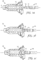
- Fig. 8 shows a drive shaft 300 and a mixer 200 according to another embodiment of the invention.
- the drive shaft 300 comprises, from the front end towards the rear end of the drive shaft 300: a guiding section 320, an engagement section 310 and a flange 301.
- the flange 301 comprises a recess 302 extending axially from the front surface into the flange 301, both structures forming a socket 303.
- the mixer 200 comprises a mixing rotor 260 having a rear end 201 extending from the rear end 202 of the mixer 200.
- the engagement section 310 of the drive shaft 300 engages with the mating engagement section 210 of the mixer 200, and the rear end 201 of the mixing rotor 260 is inserted in the recess 302 of the drive shaft 300.
- the rear end 201 of the mixing rotor is plugged into the socket 302 of the drive shaft 300.
- the rear end 201 of the mixing rotor which is often made of plastic, is reinforced by the socket 303 of the drive shaft 300, which is commonly made of metal. This enables the maximum torque transmittable from the drive shaft 300 to the mixing rotor 260 to be increased, because deformation of the engagement section 210, due to forces transmitted by the engagement section 310 of the drive shaft 300, is reduced.
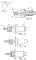
- Figs. 9a to 9c show schematic views of alternative embodiments of the mixer and the drive shaft illustrating different stages of placement of the mixer on the drive shaft.
- the mixer 420 is shown in Fig. 9a when it is separated from the drive shaft 430.
- the mixer 420 comprises a male engagement section 421 and the drive shaft 430 comprises female engagement and guiding sections 431, 432 respectively.
- the engagement section 421 of the mixer 420 has a hexagonal cross-section for mating with a hexagonal engagement section 431 of a drive shaft 430.
- other cross-sectional shapes as discussed above are encompassed.
- Fig. 9b shows the mixer 420 being placed on the guiding section 432 of the drive shaft 430.
- the guiding section 432 has a cylindrical section having a diameter equal to or slightly greater than the width between the flats of the hexagonal shape of the engagement section 421 of the mixer 420.
- the guiding section at its front end preferably comprises also a conical section (not shown).
- the mixer 420 is pushed further onto the drive shaft 430 (which may be spring-loaded as described above), so as to mate the engagement section 431 of the drive shaft with the engagement section 421 of the mixer.
- This embodiment may be considered to be the reverse of the embodiments described previously, in that the male and female portions of the various components are generally reversed.
- Fig. 10 shows a mixer of the present invention, including the material inlets.
- the mixer 20 has a front or dispensing end 28 and a rear end 29. Further the mixer comprises inlets 23, 24 and an engagement section 21.
- Fig. 11 shows a schematic view of a mixer 520 having a guiding section 532 and an engagement section 531 and a drive shaft 530 with an engagement section 521 without a guiding section.
- the guiding section of the mixer 532 may be of cylindrical and/or conical shape.
- the guiding section 532 may comprise a non-circular shape, for example as mentioned for the non-circular shapes of the guiding section of the drive shaft above.
- the drive shaft may comprise a second engagement section for engagement with the guiding section of the mixer when the mixer is placed on the drive shaft in its second position.
Landscapes
- Health & Medical Sciences (AREA)
- Engineering & Computer Science (AREA)
- General Engineering & Computer Science (AREA)
- Chemical Kinetics & Catalysis (AREA)
- Chemical & Material Sciences (AREA)
- Epidemiology (AREA)
- General Health & Medical Sciences (AREA)
- Public Health (AREA)
- Veterinary Medicine (AREA)
- Animal Behavior & Ethology (AREA)
- Life Sciences & Earth Sciences (AREA)
- Mechanical Engineering (AREA)
- Dentistry (AREA)
- Oral & Maxillofacial Surgery (AREA)
- Dental Tools And Instruments Or Auxiliary Dental Instruments (AREA)
Claims (5)
- Vorrichtung (1) zum Mischen und Abgeben von Dental-Abformmaterial, aufweisend:- einen Mischer (20) mit einem Eingriffsabschnitt (21);- eine Antriebswelle (30) zum Antreiben des Mischers (20);- wobei die Antriebswelle (30) ein Vorderende aufweist, das einen Führungsabschnitt (32) und unmittelbar am hinteren Teil separat einen Eingriffsabschnitt (31) zum Eingriff mit dem passenden Eingriffsabschnitt (21) des Mischers (20) aufweist;- wobei der Führungsabschnitt (32) der Antriebswelle (30) einen im Wesentlichen runden Querschnitt und eine zylindrische Form aufweist und der Eingriffsabschnitt (31) der Antriebswelle (30) einen nicht-runden Querschnitt aufweist, und der Mischer (20) in einer ersten und einer zweiten Position auf der Antriebswelle (30) platzierbar ist, wobei der Führungsabschnitt (32) der Antriebswelle (30) in der ersten Position mit dem Eingriffsabschnitt (21) des Mischers (20) zusammenpasst, der Eingriffsabschnitt (31) der Antriebswelle (30) jedoch nicht mit dem Eingriffsabschnitt (21) des Mischers (20) in Eingriff steht, und- in der zweiten Position der Eingriffsabschnitt (31) der Antriebswelle (30) auch mit dem Eingriffsabschnitt (21) des Mischers (20) in Eingriff steht.
- Die Vorrichtung (1) nach Anspruch 1, wobei der Eingriffsabschnitt (31) der Antriebswelle (30) einen sechseckigen Querschnitt aufweist.
- Die Vorrichtung (1) nach Anspruch 1 oder 2, ferner aufweisend eine Kammer (11, 12) zum Aufbewahren von mindestens einem Bestandteil des Dental-Abformmaterials, wobei sich die Kammer (11, 12) zu einem Auslass (13, 14) hin öffnet, der mit einem passenden Einlass (23, 24) des Mischers (20) verbindbar ist, wenn der Mischer (20) in der zweiten Position auf die Antriebswelle (30) gesetzt wird.
- Die Vorrichtung nach Anspruch 3, wobei der Auslass (13, 14) zumindest teilweise mit dem passenden Einlass (23, 24) des Mischers (20) verbindbar ist, wenn der Mischer (20) in der ersten Position auf die Antriebswelle (30) gesetzt wird.
- Die Vorrichtung nach Anspruch 3, ferner aufweisend einen Kolben (51, 52) zum Ausstoßen des mindestens einen Bestandteils aus der Kammer (11, 12) in den Mischer (20), um das Dental-Abformmaterial zu mischen und abzugeben.
Applications Claiming Priority (2)
| Application Number | Priority Date | Filing Date | Title |
|---|---|---|---|
| EP06004960A EP1836992A1 (de) | 2006-03-10 | 2006-03-10 | Mischeinheit und Antrieb für die Mischeinheit |
| PCT/US2007/063526 WO2007106701A2 (en) | 2006-03-10 | 2007-03-08 | Mixing device and drive for the mixing device |
Publications (3)
| Publication Number | Publication Date |
|---|---|
| EP1993470A2 EP1993470A2 (de) | 2008-11-26 |
| EP1993470B1 EP1993470B1 (de) | 2017-06-21 |
| EP1993470B2 true EP1993470B2 (de) | 2022-04-27 |
Family
ID=36754335
Family Applications (2)
| Application Number | Title | Priority Date | Filing Date |
|---|---|---|---|
| EP06004960A Withdrawn EP1836992A1 (de) | 2006-03-10 | 2006-03-10 | Mischeinheit und Antrieb für die Mischeinheit |
| EP07779278.6A Active EP1993470B2 (de) | 2006-03-10 | 2007-03-08 | Mischeinheit mit antrieb für die mischeinheit |
Family Applications Before (1)
| Application Number | Title | Priority Date | Filing Date |
|---|---|---|---|
| EP06004960A Withdrawn EP1836992A1 (de) | 2006-03-10 | 2006-03-10 | Mischeinheit und Antrieb für die Mischeinheit |
Country Status (3)
| Country | Link |
|---|---|
| US (1) | US8579497B2 (de) |
| EP (2) | EP1836992A1 (de) |
| WO (1) | WO2007106701A2 (de) |
Families Citing this family (23)
| Publication number | Priority date | Publication date | Assignee | Title |
|---|---|---|---|---|
| EP1836992A1 (de) * | 2006-03-10 | 2007-09-26 | 3M Innovative Properties Company | Mischeinheit und Antrieb für die Mischeinheit |
| KR101528263B1 (ko) * | 2008-07-17 | 2015-06-12 | 스떼펀 쿠비 | 유체상 충전재를 관내 공간에 주입하는 장치 |
| GB0915007D0 (en) * | 2009-08-28 | 2009-09-30 | 3M Innovative Properties Co | Mixer and system for mixing and dispensing material |
| DE102010013750A1 (de) | 2010-03-31 | 2011-07-14 | Heraeus Kulzer GmbH, 63450 | Behälter, Behältersystem und Dosiervorrichtung für ein-oder mehrkomponentige Abformmaterialien |
| EP2399666B1 (de) * | 2010-06-22 | 2013-02-20 | 3M Innovative Properties Company | Mischvorrichtung zum Herstellen eines Dentalmaterials, sowie System enthaltend einen solchen |
| DE102010045935B4 (de) | 2010-09-21 | 2014-07-17 | Heraeus Kulzer Gmbh | Behälter, Behältersystem, Verfahren zum Applizieren einer pastösen Masse aus diesem Behälter sowie Verfahren zum Mischen mehrerer Massen aus diesem Behälter |
| EP2441413A1 (de) * | 2010-10-18 | 2012-04-18 | 3M Innovative Properties Company | Mischer zur Herstellung von Zahnmaterial, System mit dem Mischer und Verfahren zur Montage des Mischers |
| IN2012DE01330A (de) * | 2011-07-22 | 2015-09-25 | Sulzer Mixpac Ag | |
| US9463079B2 (en) * | 2011-08-24 | 2016-10-11 | Kettenbach Gmbh & Co. Kg | Mixer |
| EP2606987A1 (de) * | 2011-12-21 | 2013-06-26 | Sika Technology AG | Applikationssystem, akkubetriebenes Applikationsgerät und Verfahren zur Herstellung einer Verklebung |
| JP3183618U (ja) * | 2012-03-22 | 2013-05-30 | 三菱化学株式会社 | 画像形成装置用の回転部材、画像形成カートリッジおよび画像形成装置 |
| WO2014035790A1 (en) * | 2012-08-28 | 2014-03-06 | 3M Innovative Properties Company | Device for dispensing a dental material |
| GB2506261B (en) * | 2013-07-30 | 2015-02-18 | Rolls Royce Plc | A joint |
| WO2018017742A1 (en) | 2016-07-21 | 2018-01-25 | Siemens Healthcare Diagnostics Inc. | Quick-connect mixer impeller coupling |
| DE102017112440A1 (de) * | 2017-06-06 | 2018-12-06 | Shin-Etsu Silicones Europe B.V. | Gebinde und Dosiervorrichtung für viskose Materialien |
| ES2945764T3 (es) * | 2017-08-09 | 2023-07-06 | Sika Tech Ag | Sistema para la aplicación de un material de construcción |
| US12292087B2 (en) | 2018-02-08 | 2025-05-06 | Philip Morris Products S.A. | Pair of connectable portions for connecting a transmission shaft and a roller |
| US20210394137A1 (en) * | 2018-10-02 | 2021-12-23 | Michael Josias CRONJE | Stirrer assembly |
| DE102019108533B4 (de) * | 2019-04-02 | 2020-11-19 | Kulzer Gmbh | Auspressvorrichtung für dentale Materialien und Verfahren zum Antreiben zumindest eines Austragskolbens eines Kartuschensystems mit einer Auspressvorrichtung |
| DE102019119161A1 (de) * | 2019-07-15 | 2021-01-21 | Kulzer Gmbh | Dynamischer Mischer zum benutzerfreundlichen Einlegen in eine Mischapparatur |
| KR102456489B1 (ko) * | 2020-12-22 | 2022-10-20 | 윤문규 | 치과용 인상재 전동 디스펜서 |
| DE102023111263B4 (de) | 2023-05-02 | 2025-01-23 | Kulzer Gmbh | Auspressvorrichtung für dentale Materialien mit Volumenstrom-Messvorrichtung |
| DE102023119907A1 (de) | 2023-07-27 | 2025-01-30 | Kulzer Gmbh | Adapter zum Umfüllen von Mehrkammerkartuschen |
Citations (3)
| Publication number | Priority date | Publication date | Assignee | Title |
|---|---|---|---|---|
| WO2001031216A1 (en) † | 1999-10-27 | 2001-05-03 | Abbott Laboratories | Universal style coupling |
| DE10316155A1 (de) † | 2002-05-24 | 2003-12-18 | Sew Eurodrive Gmbh & Co | Baureihe von Wellen und Verfahren zur Fertigung |
| WO2004056281A1 (de) † | 2002-12-19 | 2004-07-08 | Ernst Mühlbauer Gmbh & Co. Kg | Vorrichtung zum ausgeben einer gemischten mehrkomponentenmasse |
Family Cites Families (31)
| Publication number | Priority date | Publication date | Assignee | Title |
|---|---|---|---|---|
| US2833576A (en) * | 1955-11-15 | 1958-05-06 | Cirone Joseph | Connecting means for a mixer and a disposable mixing blade |
| US2893769A (en) | 1956-07-20 | 1959-07-07 | Deliso John | Socket and rod coupling |
| US2869907A (en) * | 1956-07-20 | 1959-01-20 | Deliso John | Socket and rod coupling |
| US3290918A (en) * | 1963-12-06 | 1966-12-13 | Anthony V Weasler | Method of manufacturing a shaft coupling |
| US3485520A (en) * | 1968-05-01 | 1969-12-23 | Rayburn G Alexander | Self-locking connection between rigid members and method of making same |
| CH614620A5 (de) * | 1977-07-05 | 1979-12-14 | Identoflex Ag | |
| US4212546A (en) * | 1978-09-21 | 1980-07-15 | Porteous Don D | Tiltable power blender for dental impression materials |
| DE3233366A1 (de) * | 1982-02-05 | 1983-09-22 | Hans Klaus 8091 Ebrach Schneider | Vorrichtung zum mischen von dentalmassen |
| US4832637A (en) * | 1987-05-29 | 1989-05-23 | Brunswick Corporation | Marine engine driveshaft coupling |
| US4832573A (en) * | 1987-11-27 | 1989-05-23 | General Motors Corporation | Integral connection for plastic water pump impeller |
| DE9017323U1 (de) | 1990-12-21 | 1992-04-16 | Thera Patent GmbH & Co KG Gesellschaft für industrielle Schutzrechte, 8031 Seefeld | Dynamischer Mischer |
| DE4301209C2 (de) | 1993-01-19 | 1995-06-08 | Maweva Holding Ag Ltd Rickenba | Handrührgerät |
| US5402710A (en) * | 1994-01-27 | 1995-04-04 | Chen; Shang-Hsien | Mixer mechanism for an automatic baking machine |
| GB9403362D0 (en) | 1994-02-22 | 1994-04-13 | Summit Medical Ltd | Bone cement mixing apparatus |
| DE29705741U1 (de) | 1997-04-01 | 1998-08-06 | Muehlbauer Ernst Kg | Dynamischer Mischer für zahnärztliche Abdruckmassen |
| US6443612B1 (en) * | 1999-12-02 | 2002-09-03 | Wilhelm A. Keller | Dynamic mixer |
| ATE272440T1 (de) | 2000-03-29 | 2004-08-15 | Heraeus Kulzer Gmbh & Co Kg | Dynamischer mischer |
| DE10019893C2 (de) | 2000-04-20 | 2003-05-28 | 3M Espe Ag | Vorrichtung in Form eines dynamischen Mischers oder einer Kartuschenfront und deren Verwendung |
| WO2002021652A1 (de) | 2000-09-04 | 2002-03-14 | Siemens Aktiengesellschaft | Abschliessvorrichtung für einschub-leistungsschalter |
| US6439760B1 (en) * | 2000-09-29 | 2002-08-27 | Deborah L. Langeloh | Mixer appliance |
| DE50110155D1 (de) | 2001-07-26 | 2006-07-27 | Muehlbauer Ernst Gmbh & Co Kg | Verfahren und Vorrichtung zum Erzeugen einer Mehrkomponentenmasse |
| DE10164385C1 (de) | 2001-12-28 | 2003-03-06 | Kettenbach Gmbh & Co Kg | Vorrichtung zum Vermischen zweier pastöser Massen, insbesondere zum Vermischen einer Dental-Abformmasse mit einer Katalysatormasse |
| CA2517014C (en) * | 2003-03-06 | 2012-07-17 | Dentsply International Inc. | Dispensing and mixing tip |
| DE10312843B3 (de) | 2003-03-21 | 2004-11-11 | A. Kettenbach Gmbh & Co. Kg | Vorrichtung zum Ausbringen von Ein- oder Mehrkomponentenmassen und Ventilanordnung hierfür |
| DE60300822T2 (de) | 2003-08-14 | 2006-04-13 | 3M Espe Ag | Mischelement für einen Mehrkomponentenpastenmischer, und Mischer mit diesem Mischelement |
| EP1602342A1 (de) * | 2004-06-04 | 2005-12-07 | 3M Espe AG | Verriegelungsanordnung und Austragkartusche mit einer derartigen Anordnung |
| EP1802385B1 (de) * | 2004-09-22 | 2008-01-23 | 3M Espe AG | Mischer für mehrkomponentenpasten, ausrüstung und verfahren zum mischen von pastenkomponenten |
| EP1836992A1 (de) * | 2006-03-10 | 2007-09-26 | 3M Innovative Properties Company | Mischeinheit und Antrieb für die Mischeinheit |
| EP1834603A1 (de) * | 2006-03-10 | 2007-09-19 | 3M Innovative Properties Company | Vorrichtung und Verfahren zur Ausgabe von zahnärztlichem Material |
| GB0915007D0 (en) * | 2009-08-28 | 2009-09-30 | 3M Innovative Properties Co | Mixer and system for mixing and dispensing material |
| GB0915002D0 (en) * | 2009-08-28 | 2009-09-30 | 3M Innovative Properties Co | Device for dispensing a dental material |
-
2006
- 2006-03-10 EP EP06004960A patent/EP1836992A1/de not_active Withdrawn
-
2007
- 2007-03-08 EP EP07779278.6A patent/EP1993470B2/de active Active
- 2007-03-08 WO PCT/US2007/063526 patent/WO2007106701A2/en not_active Ceased
- 2007-03-08 US US12/281,999 patent/US8579497B2/en active Active
Patent Citations (3)
| Publication number | Priority date | Publication date | Assignee | Title |
|---|---|---|---|---|
| WO2001031216A1 (en) † | 1999-10-27 | 2001-05-03 | Abbott Laboratories | Universal style coupling |
| DE10316155A1 (de) † | 2002-05-24 | 2003-12-18 | Sew Eurodrive Gmbh & Co | Baureihe von Wellen und Verfahren zur Fertigung |
| WO2004056281A1 (de) † | 2002-12-19 | 2004-07-08 | Ernst Mühlbauer Gmbh & Co. Kg | Vorrichtung zum ausgeben einer gemischten mehrkomponentenmasse |
Also Published As
| Publication number | Publication date |
|---|---|
| EP1836992A1 (de) | 2007-09-26 |
| US8579497B2 (en) | 2013-11-12 |
| WO2007106701A3 (en) | 2007-11-29 |
| EP1993470A2 (de) | 2008-11-26 |
| WO2007106701A2 (en) | 2007-09-20 |
| US20090279382A1 (en) | 2009-11-12 |
| EP1993470B1 (de) | 2017-06-21 |
Similar Documents
| Publication | Publication Date | Title |
|---|---|---|
| EP1993470B2 (de) | Mischeinheit mit antrieb für die mischeinheit | |
| US8371744B2 (en) | Mixer and system for mixing and dispensing a material | |
| CN102481177B (zh) | 用于分配牙科材料的装置 | |
| CA2763752C (en) | Mixing apparatus | |
| EP2066432B1 (de) | Knochenzementmischungs- und verabreichungssystem mit automatisierter knochenzementübertragung zwischen der mischungs- und der verabreichungsvorrichtung | |
| EP1989004B1 (de) | Zweiteilige doppelspritze | |
| CN102413789B (zh) | 牙科物质的分配装置 | |
| US20030183653A1 (en) | Two-part composition syringe delivery system | |
| JPH04220259A (ja) | 外科用接着剤の混合および充填装置 | |
| JP6199748B2 (ja) | カープルの作動器具及び方法 | |
| CN102946985B (zh) | 用于制备牙科材料的混合器和包括所述混合器的系统 | |
| US9486298B2 (en) | Cartridge for dispensing a dental substance and method of assembling the cartridge | |
| EP3815777B1 (de) | Misch- und ausgabesystem und verfahren zum mischen und ausgeben von material aus einem misch- und ausgabesystem | |
| EP3661637B1 (de) | Dynamischer mischer, automatische mischeinheit sowie verfahren zum installieren und antreiben eines dynamischen mischers | |
| EP2441413A1 (de) | Mischer zur Herstellung von Zahnmaterial, System mit dem Mischer und Verfahren zur Montage des Mischers | |
| EP3815639A1 (de) | Abgabemechanismus und verfahren zur abgabe von material unter verwendung eines abgabemechanismus |
Legal Events
| Date | Code | Title | Description |
|---|---|---|---|
| PUAI | Public reference made under article 153(3) epc to a published international application that has entered the european phase |
Free format text: ORIGINAL CODE: 0009012 |
|
| 17P | Request for examination filed |
Effective date: 20080916 |
|
| AK | Designated contracting states |
Kind code of ref document: A2 Designated state(s): AT BE BG CH CY CZ DE DK EE ES FI FR GB GR HU IE IS IT LI LT LU LV MC MT NL PL PT RO SE SI SK TR |
|
| RIN1 | Information on inventor provided before grant (corrected) |
Inventor name: HARRE, MANFRED Inventor name: MUELLER-PAUL, DIRK |
|
| DAX | Request for extension of the european patent (deleted) | ||
| 17Q | First examination report despatched |
Effective date: 20140429 |
|
| GRAP | Despatch of communication of intention to grant a patent |
Free format text: ORIGINAL CODE: EPIDOSNIGR1 |
|
| STAA | Information on the status of an ep patent application or granted ep patent |
Free format text: STATUS: GRANT OF PATENT IS INTENDED |
|
| RIC1 | Information provided on ipc code assigned before grant |
Ipc: A61C 9/00 20060101ALI20170116BHEP Ipc: F16D 1/10 20060101ALI20170116BHEP Ipc: B01F 15/00 20060101ALI20170116BHEP Ipc: B01F 7/00 20060101AFI20170116BHEP |
|
| INTG | Intention to grant announced |
Effective date: 20170209 |
|
| GRAS | Grant fee paid |
Free format text: ORIGINAL CODE: EPIDOSNIGR3 |
|
| GRAJ | Information related to disapproval of communication of intention to grant by the applicant or resumption of examination proceedings by the epo deleted |
Free format text: ORIGINAL CODE: EPIDOSDIGR1 |
|
| GRAL | Information related to payment of fee for publishing/printing deleted |
Free format text: ORIGINAL CODE: EPIDOSDIGR3 |
|
| STAA | Information on the status of an ep patent application or granted ep patent |
Free format text: STATUS: EXAMINATION IS IN PROGRESS |
|
| REG | Reference to a national code |
Ref country code: DE Ref legal event code: R079 Ref document number: 602007051415 Country of ref document: DE Free format text: PREVIOUS MAIN CLASS: A61C0009000000 Ipc: A61C0005640000 |
|
| GRAR | Information related to intention to grant a patent recorded |
Free format text: ORIGINAL CODE: EPIDOSNIGR71 |
|
| STAA | Information on the status of an ep patent application or granted ep patent |
Free format text: STATUS: GRANT OF PATENT IS INTENDED |
|
| GRAA | (expected) grant |
Free format text: ORIGINAL CODE: 0009210 |
|
| STAA | Information on the status of an ep patent application or granted ep patent |
Free format text: STATUS: THE PATENT HAS BEEN GRANTED |
|
| INTC | Intention to grant announced (deleted) | ||
| RIC1 | Information provided on ipc code assigned before grant |
Ipc: A61C 9/00 20060101ALI20170420BHEP Ipc: B01F 15/00 20060101ALI20170420BHEP Ipc: B01F 7/00 20060101ALI20170420BHEP Ipc: A61C 5/64 20170101AFI20170420BHEP Ipc: F16D 1/10 20060101ALI20170420BHEP |
|
| AK | Designated contracting states |
Kind code of ref document: B1 Designated state(s): AT BE BG CH CY CZ DE DK EE ES FI FR GB GR HU IE IS IT LI LT LU LV MC MT NL PL PT RO SE SI SK TR |
|
| INTG | Intention to grant announced |
Effective date: 20170512 |
|
| REG | Reference to a national code |
Ref country code: GB Ref legal event code: FG4D |
|
| REG | Reference to a national code |
Ref country code: CH Ref legal event code: EP |
|
| REG | Reference to a national code |
Ref country code: IE Ref legal event code: FG4D |
|
| REG | Reference to a national code |
Ref country code: AT Ref legal event code: REF Ref document number: 902243 Country of ref document: AT Kind code of ref document: T Effective date: 20170715 |
|
| REG | Reference to a national code |
Ref country code: DE Ref legal event code: R096 Ref document number: 602007051415 Country of ref document: DE |
|
| REG | Reference to a national code |
Ref country code: NL Ref legal event code: MP Effective date: 20170621 |
|
| PG25 | Lapsed in a contracting state [announced via postgrant information from national office to epo] |
Ref country code: FI Free format text: LAPSE BECAUSE OF FAILURE TO SUBMIT A TRANSLATION OF THE DESCRIPTION OR TO PAY THE FEE WITHIN THE PRESCRIBED TIME-LIMIT Effective date: 20170621 Ref country code: GR Free format text: LAPSE BECAUSE OF FAILURE TO SUBMIT A TRANSLATION OF THE DESCRIPTION OR TO PAY THE FEE WITHIN THE PRESCRIBED TIME-LIMIT Effective date: 20170922 Ref country code: LT Free format text: LAPSE BECAUSE OF FAILURE TO SUBMIT A TRANSLATION OF THE DESCRIPTION OR TO PAY THE FEE WITHIN THE PRESCRIBED TIME-LIMIT Effective date: 20170621 |
|
| REG | Reference to a national code |
Ref country code: LT Ref legal event code: MG4D |
|
| REG | Reference to a national code |
Ref country code: AT Ref legal event code: MK05 Ref document number: 902243 Country of ref document: AT Kind code of ref document: T Effective date: 20170621 |
|
| PG25 | Lapsed in a contracting state [announced via postgrant information from national office to epo] |
Ref country code: LV Free format text: LAPSE BECAUSE OF FAILURE TO SUBMIT A TRANSLATION OF THE DESCRIPTION OR TO PAY THE FEE WITHIN THE PRESCRIBED TIME-LIMIT Effective date: 20170621 Ref country code: SE Free format text: LAPSE BECAUSE OF FAILURE TO SUBMIT A TRANSLATION OF THE DESCRIPTION OR TO PAY THE FEE WITHIN THE PRESCRIBED TIME-LIMIT Effective date: 20170621 Ref country code: BG Free format text: LAPSE BECAUSE OF FAILURE TO SUBMIT A TRANSLATION OF THE DESCRIPTION OR TO PAY THE FEE WITHIN THE PRESCRIBED TIME-LIMIT Effective date: 20170921 Ref country code: NL Free format text: LAPSE BECAUSE OF FAILURE TO SUBMIT A TRANSLATION OF THE DESCRIPTION OR TO PAY THE FEE WITHIN THE PRESCRIBED TIME-LIMIT Effective date: 20170621 |
|
| PG25 | Lapsed in a contracting state [announced via postgrant information from national office to epo] |
Ref country code: EE Free format text: LAPSE BECAUSE OF FAILURE TO SUBMIT A TRANSLATION OF THE DESCRIPTION OR TO PAY THE FEE WITHIN THE PRESCRIBED TIME-LIMIT Effective date: 20170621 Ref country code: SK Free format text: LAPSE BECAUSE OF FAILURE TO SUBMIT A TRANSLATION OF THE DESCRIPTION OR TO PAY THE FEE WITHIN THE PRESCRIBED TIME-LIMIT Effective date: 20170621 Ref country code: AT Free format text: LAPSE BECAUSE OF FAILURE TO SUBMIT A TRANSLATION OF THE DESCRIPTION OR TO PAY THE FEE WITHIN THE PRESCRIBED TIME-LIMIT Effective date: 20170621 Ref country code: CZ Free format text: LAPSE BECAUSE OF FAILURE TO SUBMIT A TRANSLATION OF THE DESCRIPTION OR TO PAY THE FEE WITHIN THE PRESCRIBED TIME-LIMIT Effective date: 20170621 Ref country code: RO Free format text: LAPSE BECAUSE OF FAILURE TO SUBMIT A TRANSLATION OF THE DESCRIPTION OR TO PAY THE FEE WITHIN THE PRESCRIBED TIME-LIMIT Effective date: 20170621 |
|
| PG25 | Lapsed in a contracting state [announced via postgrant information from national office to epo] |
Ref country code: IS Free format text: LAPSE BECAUSE OF FAILURE TO SUBMIT A TRANSLATION OF THE DESCRIPTION OR TO PAY THE FEE WITHIN THE PRESCRIBED TIME-LIMIT Effective date: 20171021 Ref country code: ES Free format text: LAPSE BECAUSE OF FAILURE TO SUBMIT A TRANSLATION OF THE DESCRIPTION OR TO PAY THE FEE WITHIN THE PRESCRIBED TIME-LIMIT Effective date: 20170621 Ref country code: IT Free format text: LAPSE BECAUSE OF FAILURE TO SUBMIT A TRANSLATION OF THE DESCRIPTION OR TO PAY THE FEE WITHIN THE PRESCRIBED TIME-LIMIT Effective date: 20170621 Ref country code: PL Free format text: LAPSE BECAUSE OF FAILURE TO SUBMIT A TRANSLATION OF THE DESCRIPTION OR TO PAY THE FEE WITHIN THE PRESCRIBED TIME-LIMIT Effective date: 20170621 |
|
| REG | Reference to a national code |
Ref country code: DE Ref legal event code: R026 Ref document number: 602007051415 Country of ref document: DE |
|
| PLBI | Opposition filed |
Free format text: ORIGINAL CODE: 0009260 |
|
| PLAX | Notice of opposition and request to file observation + time limit sent |
Free format text: ORIGINAL CODE: EPIDOSNOBS2 |
|
| 26 | Opposition filed |
Opponent name: KULZER GMBH Effective date: 20180320 Opponent name: RENFERT GMBH Effective date: 20180321 |
|
| PG25 | Lapsed in a contracting state [announced via postgrant information from national office to epo] |
Ref country code: DK Free format text: LAPSE BECAUSE OF FAILURE TO SUBMIT A TRANSLATION OF THE DESCRIPTION OR TO PAY THE FEE WITHIN THE PRESCRIBED TIME-LIMIT Effective date: 20170621 |
|
| PLBB | Reply of patent proprietor to notice(s) of opposition received |
Free format text: ORIGINAL CODE: EPIDOSNOBS3 |
|
| PG25 | Lapsed in a contracting state [announced via postgrant information from national office to epo] |
Ref country code: SI Free format text: LAPSE BECAUSE OF FAILURE TO SUBMIT A TRANSLATION OF THE DESCRIPTION OR TO PAY THE FEE WITHIN THE PRESCRIBED TIME-LIMIT Effective date: 20170621 |
|
| REG | Reference to a national code |
Ref country code: CH Ref legal event code: PL |
|
| GBPC | Gb: european patent ceased through non-payment of renewal fee |
Effective date: 20180308 |
|
| PG25 | Lapsed in a contracting state [announced via postgrant information from national office to epo] |
Ref country code: MC Free format text: LAPSE BECAUSE OF FAILURE TO SUBMIT A TRANSLATION OF THE DESCRIPTION OR TO PAY THE FEE WITHIN THE PRESCRIBED TIME-LIMIT Effective date: 20170621 |
|
| REG | Reference to a national code |
Ref country code: BE Ref legal event code: MM Effective date: 20180331 |
|
| REG | Reference to a national code |
Ref country code: IE Ref legal event code: MM4A |
|
| PG25 | Lapsed in a contracting state [announced via postgrant information from national office to epo] |
Ref country code: LU Free format text: LAPSE BECAUSE OF NON-PAYMENT OF DUE FEES Effective date: 20180308 |
|
| PG25 | Lapsed in a contracting state [announced via postgrant information from national office to epo] |
Ref country code: IE Free format text: LAPSE BECAUSE OF NON-PAYMENT OF DUE FEES Effective date: 20180308 |
|
| PG25 | Lapsed in a contracting state [announced via postgrant information from national office to epo] |
Ref country code: GB Free format text: LAPSE BECAUSE OF NON-PAYMENT OF DUE FEES Effective date: 20180308 Ref country code: BE Free format text: LAPSE BECAUSE OF NON-PAYMENT OF DUE FEES Effective date: 20180331 Ref country code: LI Free format text: LAPSE BECAUSE OF NON-PAYMENT OF DUE FEES Effective date: 20180331 Ref country code: CH Free format text: LAPSE BECAUSE OF NON-PAYMENT OF DUE FEES Effective date: 20180331 |
|
| PG25 | Lapsed in a contracting state [announced via postgrant information from national office to epo] |
Ref country code: FR Free format text: LAPSE BECAUSE OF NON-PAYMENT OF DUE FEES Effective date: 20180331 |
|
| PG25 | Lapsed in a contracting state [announced via postgrant information from national office to epo] |
Ref country code: MT Free format text: LAPSE BECAUSE OF NON-PAYMENT OF DUE FEES Effective date: 20180308 |
|
| PG25 | Lapsed in a contracting state [announced via postgrant information from national office to epo] |
Ref country code: TR Free format text: LAPSE BECAUSE OF FAILURE TO SUBMIT A TRANSLATION OF THE DESCRIPTION OR TO PAY THE FEE WITHIN THE PRESCRIBED TIME-LIMIT Effective date: 20170621 |
|
| PG25 | Lapsed in a contracting state [announced via postgrant information from national office to epo] |
Ref country code: PT Free format text: LAPSE BECAUSE OF FAILURE TO SUBMIT A TRANSLATION OF THE DESCRIPTION OR TO PAY THE FEE WITHIN THE PRESCRIBED TIME-LIMIT Effective date: 20170621 Ref country code: HU Free format text: LAPSE BECAUSE OF FAILURE TO SUBMIT A TRANSLATION OF THE DESCRIPTION OR TO PAY THE FEE WITHIN THE PRESCRIBED TIME-LIMIT; INVALID AB INITIO Effective date: 20070308 |
|
| PG25 | Lapsed in a contracting state [announced via postgrant information from national office to epo] |
Ref country code: CY Free format text: LAPSE BECAUSE OF FAILURE TO SUBMIT A TRANSLATION OF THE DESCRIPTION OR TO PAY THE FEE WITHIN THE PRESCRIBED TIME-LIMIT Effective date: 20170621 |
|
| REG | Reference to a national code |
Ref country code: CH Ref legal event code: PK Free format text: TITEL |
|
| PUAH | Patent maintained in amended form |
Free format text: ORIGINAL CODE: 0009272 |
|
| STAA | Information on the status of an ep patent application or granted ep patent |
Free format text: STATUS: PATENT MAINTAINED AS AMENDED |
|
| 27A | Patent maintained in amended form |
Effective date: 20220427 |
|
| AK | Designated contracting states |
Kind code of ref document: B2 Designated state(s): AT BE BG CH CY CZ DE DK EE ES FI FR GB GR HU IE IS IT LI LT LU LV MC MT NL PL PT RO SE SI SK TR |
|
| REG | Reference to a national code |
Ref country code: DE Ref legal event code: R102 Ref document number: 602007051415 Country of ref document: DE |
|
| P01 | Opt-out of the competence of the unified patent court (upc) registered |
Effective date: 20230530 |
|
| REG | Reference to a national code |
Ref country code: DE Ref legal event code: R081 Ref document number: 602007051415 Country of ref document: DE Owner name: SOLVENTUM INTELLECTUAL PROPERTIES CO. (N.D.GES, US Free format text: FORMER OWNER: 3M INNOVATIVE PROPERTIES COMPANY, SAINT PAUL, MINN., US |
|
| PGFP | Annual fee paid to national office [announced via postgrant information from national office to epo] |
Ref country code: DE Payment date: 20250218 Year of fee payment: 19 |