EP1993295A1 - Telekommunikationsanordnung mit einem inneren und einem äußeren Rahmen - Google Patents
Telekommunikationsanordnung mit einem inneren und einem äußeren Rahmen Download PDFInfo
- Publication number
- EP1993295A1 EP1993295A1 EP07113494A EP07113494A EP1993295A1 EP 1993295 A1 EP1993295 A1 EP 1993295A1 EP 07113494 A EP07113494 A EP 07113494A EP 07113494 A EP07113494 A EP 07113494A EP 1993295 A1 EP1993295 A1 EP 1993295A1
- Authority
- EP
- European Patent Office
- Prior art keywords
- telecommunication
- inner frame
- frame
- outer frame
- assembly according
- Prior art date
- Legal status (The legal status is an assumption and is not a legal conclusion. Google has not performed a legal analysis and makes no representation as to the accuracy of the status listed.)
- Ceased
Links
Images

Classifications
-
- H—ELECTRICITY
- H04—ELECTRIC COMMUNICATION TECHNIQUE
- H04Q—SELECTING
- H04Q1/00—Details of selecting apparatus or arrangements
- H04Q1/02—Constructional details
- H04Q1/14—Distribution frames
- H04Q1/149—Wireguides in connector blocks
-
- H—ELECTRICITY
- H04—ELECTRIC COMMUNICATION TECHNIQUE
- H04Q—SELECTING
- H04Q1/00—Details of selecting apparatus or arrangements
- H04Q1/02—Constructional details
- H04Q1/09—Frames or mounting racks not otherwise provided for
-
- H—ELECTRICITY
- H04—ELECTRIC COMMUNICATION TECHNIQUE
- H04Q—SELECTING
- H04Q1/00—Details of selecting apparatus or arrangements
- H04Q1/02—Constructional details
- H04Q1/14—Distribution frames
- H04Q1/142—Terminal blocks for distribution frames
Definitions
- the invention relates to a telecommunication assembly for termination modules having electrical contacts for connecting wires with an inner frame and an outer frame.
- telecommunication modules In the field of telecommunication, numerous customers are connected with the switch of a telecommunication company via telecommunication lines. The customers can also be called subscribers.
- the switch is also called an exchange. Between the subscriber and the switch, sections of the telecommunication lines are connected with telecommunication modules.
- the telecommunication modules establish an electrical connection between a wire which is attached to the telecommunication module at a first side, and another wire which is attached to the telecommunication module at a second side.
- Plural telecommunication modules can be put together at a distribution point, such as a main distribution frame, an intermediate distribution frame, an outside cabinet or a distribution point located, for example in an office building or a particular floor of an office building.
- some telecommunication lines are connected with first telecommunication modules in a manner to constitute a permanent connection. Flexibility is realized by so called jumpers, which flexibly connect contacts of the first telecommunication module with contacts of a second telecommunication module. These jumpers can be changed when a person moves within an office building or with his home to provide a different telephone (i.e. a different telephone line) with a certain telephone number, which the relocated person intends to keep.
- ADSL-technology has spread widely in the field of telecommunication.
- This technology allows at least two different signals to be transmitted on a single line. This is achieved by transmitting the different signals at different frequencies along the same line.
- the signals are combined at a particular point in the telecommunication line and split at another point.
- voice and data signals which are separate, are combined and sent to the central office via the same line.
- the central office In the central office the combined signal is split.
- voice and data signals are combined at the central office, sent to the subscriber and split at the subscriber side.
- the so-called POTS-signal plain old telephone service
- splitters which are used to split or combine the signal, can generally be arranged at any distribution point.
- a POTS wire or POTS jumper indicates a wire, which is connected with an exchange of the telecommunication company.
- a line connection indicates a wire, which leads to the subscriber or customer.
- a DSLAM-wire means a wire which is connected with a DSLAM and thus, can, for example, transmit data.
- a DSLAM Digital Subscriber Line Access Multiplexer
- DE 102 36 361 B4 discloses a telecommunication module for use within an assembly for establishing an electrical connection between a wire that is attached to the first side of the module and a wire that is attached to the other side of the module.
- the module comprises a housing with openings on both sides for rows of contacts.
- the housing may be fixed on two round mounting rails. Several housings may be attached on top of each other at the mounting rails.
- EP 0 901 294 A2 discloses a telecommunication module with a frame for a plurality of connectors with several contacts. Every connector is attached separately to the frame. Between two connectors a partition member is arranged.
- EP 0 486 331 A2 discloses a telecommunication module with an U-shaped frame for connecting single modules thereto.
- the modules comprise electrical contacts and electronic components such as electronic printed circuit boards.
- the modules are connected to a first connector assembly within the frame.
- the first connectors are arranged in the middle of the U-shaped frame.
- a second connector assembly is arranged at the rear side of the U-shaped frame. There is a space between the two connector assemblies.
- the first and second connector assemblies are connected by wires.
- EP 1 455 419 A1 discloses a telecommunication module with a carrier comprising two side walls and a mounting means in order to allow the carrier to be mounted to a suitable equipment.
- the telecommunication module is provided with several connectors at the top, the bottom and/or the side for establishing an electrical connection.
- US 2006/0 264 117 A1 discloses a telecommunication assembly for mounting an insulation displacement connector block with an outer frame and at least one sub frame for carrying a connector block wherein the sub frame is detachably fixed at the outer frame.
- the present invention provides a telecommunication assembly comprising termination modules having electrical contacts for connecting wires, an outer frame and at least one inner frame for carrying a predetermined number of termination modules, the inner frame is detachably fixed at the outer frame wherein the inner and the outer frame enclose a space.
- the telecommunication assembly according to the invention has two back mount frames, a first outer frame and a second inner frame.
- the inner frame carries a predetermined number of termination modules.
- the inner frame is detachably fixed at the outer frame.
- the concept of having an inner and an outer frame helps to provide different modular mounting levels, e.g. one level could be the space.
- To have a modular system helps to mount the assembly step by step according to the actual requirements.
- the telecommunication assembly described herein comprises contacts which are adapted to connect wires therewith.
- a contact generally means any component which is adapted to establish electrical connection with at least one wire.
- the contact can, for example, at a first end thereof, be formed as an insulation displacement contact (IDC), a wire wrap contact or in any other suitable manner.
- IDC insulation displacement contact
- a wire can be connected at the first end of the contact, and at a second end of the contact, an electrical connection with a further component can be established.
- the second end of the contact can, for example, be formed as a tab, which is in electrical connection with the tab of an opposing contact which is, at the first end thereof, substantially formed as the above described first contact. In this case, the tabs, which are in contact with each other, form a disconnection point.
- an outside contact of a telecommunication component such as a protection plug or magazine, a test plug or a splitter module
- the signal which is transmitted from the wire to the contact is further transmitted to the telecommunication component (for example the splitter module) and can be processed by this module.
- all of the current is re-routed through the telecommunication component.
- the outside component is for example a testing device
- an electrical connection forming a branch to the testing device can be established at the disconnection point.
- contacts of a row of POTS-contacts on the one hand, can be provided with such a disconnection point. In this manner, a so-called lifeline service can be provided by connecting the mentioned contacts with each other (without splitting a DSLAM), and thus provide POTS service alone.
- the telecommunication module is particularly suitable for being combined with at least one splitter circuit.
- splitter circuits comprise suitable filters, such as low pass and high pass filters, to split the combined signal as described above. But a reference to a “splitter” may also be understood in appropriate circumstances to be a reference to what could be called a "combiner”.
- the splitter circuit as described above comprise an electrical circuit which splits or combines a signal.
- the predetermined number of termination modules in the inner frame may be of the kind that the number of the contacts of all termination modules together corresponds to a standard number for contacts for electronic components such as for example to the number of contacts or channels of one DSLAM printed circuit board. That is advantageous because the contacts of the inner module may be grouped and connected with the electronic component by using only one cable.
- the inner frame could be fixed at the outer frame. It is also possible to fix the inner frame at any kind of mounting means for the telecommunication assembly.
- the inner frame may be U-shaped. It typically comprises a base portion and two legs extending at both ends of the base. Such a frame is easy to manufacture and therefore low priced.
- the outer frame may be a U-shaped frame with a base portion and two legs extending at both ends of the base as well. Any other shape for the frames is possible as well such as for example a L-shape, a H-, F- or a C-shape, an A-shape, two L-shaped frames, a box with one open side or only a base portion.
- the inner and the outer frame may be made out of metal. U-shaped frame parts out of metal are easy to manufacture e.g. by bending and therefore cost-effective in the production.
- the frames may of course be manufactured out of other materials such as for example plastics and/or aluminium, magnesium, zinc, etc.. In this case they could easily be manufactured by injection moulding. If plastics are used extrusion is another possibility of production. If metals are used the frame may be profiles swelled or screwed together or die cast parts. It is also possible to use profiles with several chambers and/or ribs. The chambers an ribs may help to better organize the cables and/or wires.
- the inner frame may comprise fixing and/or centring elements for fixing and/or centring the inner frame to the outer frame. Integrating the fixing and/or centring elements into the inner frame provides the advantage that no further fixing and/or centring elements are necessary while assembling the telecommunication assembly. That also provides an advantage with respect to the costs of the assembly.
- the fixing elements may be designed as a snap fit. For example a nose may be formed into the inner frame that engages with a recess and/or an opening of the outer frame. All other known fixing elements such as bolts, screws, brackets may be used as well.
- the centring elements may be designed in the shape of protrusions formed into the inner frame that engages with a recess and/or opening of the outer frame. When the inner and the outer frame consist of metal the fixing and/or centring elements could easily be formed into the frames for example by stamping. When the inner and the outer frame consists of plastics the fixing and/or centring elements could easily be formed by moulding.
- the inner frame may carry at least one wire guide housing.
- the wire guide housings may be fixed to the termination modules of the telecommunication assembly. When the wire guide housings are fixed to the inner frame they may be connected to the inner frame even when the termination module is being pulled out of the telecommunication assembly, for example, while being replaced. This provides the advantage that the wires can stay in the wire guide housing and keep their correlation to the contacts of the termination module they belong to even if the connection of the wires to the contacts is temporarily interrupted.
- the inner frame may comprise at least one telecommunication component such as electronic components as printed circuit boards for splitter modules and the like or intelligent devices, protection components such as over-voltage and/or overcurrent protectors.
- the telecommunication component may be attached to the termination module and/or the inner frame.
- the inner frame may also comprise at least one aperture allowing electrical contact from outside the frame to the telecommunication components of the inner frame.
- the electrical contact to the telecommunication components of the inner frame may be achieved by at least one plug. Therefore, the inner frame may comprise a connector assembly inside of the aperture.
- the connector assembly may be adapted to connectors of the telecommunication components as well as to the connector field of the plug. Instead or in addition to the plug the electrical contact may be achieved by at least one bus assembly.
- the connector assembly may also be part of the telecommunication component and or the termination module.
- the plug may be arranged in the space between the inner and the outer frame. By arranging the plug in this space the additional level of the telecommunication assembly is used for guiding cables there through. This helps to clearly arrange the cables within the assembly and to get a clearly structured assembly.
- the inner frame may comprise at least one wire guide element for guiding wires from outside the inner frame to the contacts of the termination module of the inner frame.
- the wire guide element may be fixed at the inner frame. It may be integral with the inner frame or detachable mounted at the inner frame. It is also possible to attach the wire guide element to the termination modules or to the telecommunication components.
- the inner frame typically comprises receptacles for receiving fixing elements of the termination module.
- the receptacles may be in the shape of an opening or a cavity in the inner frame.
- the receptacles may be in the shape of a threaded bore. So any kind of common fixing means may be used such as a latch or plug-in system with for example dovetails or the like.
- the inner frame generally comprises openings for receiving fixing and/or guiding elements of the telecommunication components. These openings may also be in the shape of openings, cavities, slots, bores, rails or the like depending on the kind of fixing element the telecommunication components comprise.
- openings may also be in the shape of openings, cavities, slots, bores, rails or the like depending on the kind of fixing element the telecommunication components comprise.
- the outer frame may comprise openings for accommodating fixing elements and/or guide rails for accommodating guiding elements of the inner frame.
- a very easy way to fix the inner frame to the outer frame is a snap fit.
- a snap fit may, for example, be achieved by providing a nose in one of the frames and a corresponding reception in the other frame.
- the outer frame may be mounted to mounting rails. Any other mounting structure may be used such as for example racks, profiles as well as ribs in housings.
- the telecommunication module described herein can be used by itself, i.e., a distribution point can be equipped with this telecommunication module step by step in order to prepare to provide ADSL service to a growing number of subscribers.
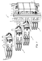
- Fig. 1 shows a telecommunication assembly 1 comprising an outer frame 2 mounted at two mounting rails 3 and several inner frames 4.
- the smaller inner frames 4 are arranged as modules inside the outer frame 2.
- the outer frame 2 is U-shaped and comprises a base part 5 and two legs 6. It is mounted by screws 7 and fixing elements 8 to the mounting rails 3.
- the base part 5 comprises openings 9 that are arranged in rows. Cable ties (not shown) could be fixed thereon.
- the two legs 6 comprise guiding rails 11 for receiving guiding elements 12 of the inner frames 4.
- the guiding elements 12 will be described in detail below.
- the two legs 6 also comprise openings 13 for receiving fixing elements 14 of the inner frames 4.
- the fixing elements 14 of the inner frames 4 will be described in detail below.
- the outer frame 2 is made out of metal.
- the inner frames 4 are also made out of similar metal. They are U-shaped as well and provide a base part 15 and two legs 16.
- the base part 15 of the inner frame comprises openings 17 for guiding elements 18 of telecommunication components 24 that will be described in detail below.
- the two legs 16 comprise guiding elements 12 and fixing elements 14.
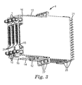
- the fixing elements 14 are rectangular tabs provided by cutting-out or stamping from the metal material of the inner frame. They are cut out at three sides and connected at one side to the leg 16 and bend in the direction outside of the inner frames 4.
- the fixing elements 14 can best be seen in Fig. 3 where they protrude over the leg 16 of the inner frame 4. By protruding over the leg 16 they engaging with the opening 13 of the outer frame 2.
- the guiding elements 12 are rectangular tabs provided by cutting-out or stamping from the metal material of the inner frame. They are cut out at only two sides and connected at two sides to the leg 16.
- the guiding elements 12 can best be seen in Fig. 3 where they protrude over the leg 16 of the inner frame 4 as well. By protruding over the leg 16 they interact with the guiding rails 11 of the outer frame.
- the inner frames 4 comprise three modules 19 that can be seen best in Fig. 2 and will now be described with reference to that Figure.
- Fig. 2 shows one inner frame 4 with a base part 15 and two legs 16.
- the legs 16 comprise the described fixing elements 14 and guiding elements 12.
- Inside of the U-shaped inner frame 4 three modules 19 are arranged.
- one of the modules 19 is pulled out of the inner frame 4.
- the modules 19 each comprise a housing 25, a termination module 21 with two rows 22 of electrical contacts on the front side, wire guide housings 23 on a top and bottom portion of the module 19 and telecommunication components 24 such as for example splitter units.
- telecommunication components 24 such as for example splitter units.
- terminal module 21, wire guide housings 23 and telecommunication component 24 are separate parts since the module 19 comprises the housing 25 containing at least the telecommunication component 24, the wire guide housings 23 and the termination module 21.
- the termination module 21 is detachably fixed to the front side of the housing 25 by two fixing legs 26, one on each transverse side of the termination module 21 (only one can be seen in Fig. 2 ).
- the fixing legs 26 act as snap fits fixing the termination module 21 temporarily to the housing 25.
- the housing 25 also comprises wire guide rings 27 (only one can be seen in Fig. 2 ) on each transverse side for guiding wires and/or cables from outside the inner frame 4 to the wire guide housings 23 of the inner frame 4.
- the housing 25 further comprises guiding elements or pins 18 pointing in the direction of the base part 15 of the inner frame 4 and interacting with the openings 17 (see Fig. 1 ) in the base part 15 of the inner frame 4.
- contacts of the telecommunication component 24 in the shape of pins 28 also pointing in the direction of the base part 15 of the inner frame 4.
- the pins 28 extend through further openings 29 in the base part 15 of the inner frame 4 (see Fig. 3 ). To prevent that the pins 28 will be destroyed, e.g.
- the modules 19 also comprise fixing legs 32 for fixing the modules 19 to the inner frame 4.
- the inner frame 4 comprises openings 33 (one can be seen in Fig. 2 ) for interacting with the fixing legs 32 to secure the modules to the inner frame.
- a plug 34 for making electrical contact with the pins 28 is shown as well.
- the plug 34 comprises a housing 39 and a cable 35. Both parts will be described in detail with reference to Fig. 5 and 6 .
- Fig. 1 the interaction between the inner frames 4 and the outer frame 2 is shown.
- the first contact is made between the guiding elements 12 of the inner frame 4 and the guiding rails 11 of the outer frame 2.
- the guiding elements 12 lead the inner frames 4 along the legs 6 of the outer frame 2 to their end position which is defined by the length of the guiding rails 11.
- the guiding elements 12 abut the end of the guiding rails 11 the inner frames 4 have reached their end position. It is also possible to use dead stops to define an end position. In the described embodiment of the invention in this end position, the base parts 15 of the inner frames 4 do not contact the base part 5 of the outer frame 2.
- the inner frames 4 and the outer frame 2 encloses a space 36 (see Fig. 4 ).
- the fixing elements 14 interact with the openings 13. This prevents a slipping out of the inner frames 4.
- the distance between the legs 6 of the outer frame 2 corresponds to the width of the inner frames 4 without any components mounted there between.
- the fixing legs 32 on the sides of module 19 encompass leg 16 of the inner frame 4 as well as leg 6 of the outer frame 2. Therefore the outer frame 2 provides receiving portions 37 for receiving the fixing legs 32.
- One receiving portion 37 is identical with the guiding rail 11 for the guiding element 12 of the inner frame 4.
- contacts for 24 subscribers are arranged, on one termination module are contacts for 8 subscribers.
- Twenty four is the number of contacts or channels for a standard DSLAM PCB that is usually mounted at another place. Since 24 contacts are grouped together they can easily be connected to the DSLAM PCB via one plug 34 and one cable 35. Because of the modular structure and a lot of detachably fixing elements it is possible to demount any single module, for example, inner frame to exchange a component inside the module.
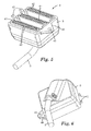
- Fig. 4 shows a perspective view on top of the telecommunication assembly 1 according to the invention showing the different mounting levels (I, II, III) of the assembly. It shows the outer frame 2, two mounting rails 3 and the top inner frame 4 as well as the module housing 25 with the top termination module 21.
- the embodiment shown in this Figure does provide three different mounting levels (I, II, III) for cables.
- a first level I is the space behind the outer frame 2, where main cables or distribution cables 38 are arranged.
- a second level II is the space 36 between the inner frames 4 and the outer frame 2.
- This space 36 may be used for other cables such as cables for DSLAM, bus cables and or optical fibre cables.
- Fig. 4 shows a plug 34 with cables 35 which lead to a remotely located DSLAM PCB.
- a third level III is on a level with the inner frames 4, where cables can be jumpered e.g. POTS cables, line cables and/or DSLAM cables.
- Fig. 4 also shows the run of a few wires coming out of the main cable or distribution cable 38 (level I). From this level they are guided along the side of the telecommunication module 1 through the mounting rail 3, through a wire guide ring 27 and into a wire guide housing 23 (level III). Coming out of the wire guide housing 23, the wires are connected to the electrical contacts of the termination module 21.
- wires and/or cables for an electrical connection with a DSLAM assembly may be arranged.
- one plug 34 may be used for simultaneously connecting all contacts of the three termination modules 21 inside of one inner frame 4 at a time (see Fig. 5 and 6 ). Instead of using several plugs one plug 34 is used. By using one plug 34 misalignments can be prevented.
- the plug 34 may be connected to a cable 35 which leads to any kind of electronic or intelligent device such as for example a DSLAM assembly.
- the plug 34 comprises a housing 39 containing three single strips 41 with receptacles 42 for the pins 28 of the telecommunication components 24.
- the receptacles 42 are arranged in two rows at a strip 41 to form a socket.
- the strips 41 of the plug 34 may comprise sockets ( Fig. 5 ) or card edges (not shown). It is also possible to arrange a PCB inside of the housing 39 of the plug 34.
- the plug 34 may also be connected to different kinds of cables such as for example to a bus cable and/or to telecommunication cables. In both cases a PCB may be integrated in the housing 39 of the plug 34 whereby the sockets are mounted onto the PCB. The different kinds of cables are terminated in the single strips 41 which are in the mounted stage connected to the telecommunication module 24 inside the inner frame 4.
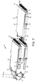
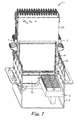
- Fig. 7 shows a perspective view of another embodiment of a telecommunication assembly 1 according to the invention with an outer frame 2 and an inner frame 4.
- the main difference between the embodiment described before and the embodiment shown in Fig. 7 is that another concept of connecting the telecommunication components 24 is shown. Instead of only having one plug 34 connecting all three telecommunication components 24 of one inner frame 4 at a time, there is one plug 34 for example for connecting the telecommunication components 24 to a DSLAM and one common bus 46 for connecting all modules inside of the outer frame.
- the bus may be used for controlling the telecommunication components 24, for example, for switching them on or off. If a subscriber wants to change his telecommunication service, this could easily be done by switching the service on or off via the bus connection.
Priority Applications (8)
| Application Number | Priority Date | Filing Date | Title |
|---|---|---|---|
| RU2009139957/07A RU2407225C1 (ru) | 2007-05-14 | 2008-04-30 | Комплект телекоммуникационного оборудования с внутренней и внешней рамами |
| PCT/US2008/061986 WO2008144181A1 (en) | 2007-05-14 | 2008-04-30 | Telecommunication assembly with an inner frame and an outer frame |
| US12/597,094 US20100130057A1 (en) | 2007-05-14 | 2008-04-30 | Telecommunication assembly with an inner frame and an outer frame |
| BRPI0811257-6A2A BRPI0811257A2 (pt) | 2007-05-14 | 2008-04-30 | Conjunto de telecomunicação com uma estrutura interna e uma estrutura externa. |
| CN200880016133A CN101682801A (zh) | 2007-05-14 | 2008-04-30 | 具有内框架和外框架的通信组件 |
| MX2009012215A MX2009012215A (es) | 2007-05-14 | 2008-04-30 | Conjunto para telecomunicaciones con un armazon interno y un armazon externo. |
| TW097116681A TW200913733A (en) | 2007-05-14 | 2008-05-06 | Telecommunication assembly with an inner frame and an outer frame |
| ARP080102011A AR066541A1 (es) | 2007-05-14 | 2008-05-13 | Conjunto para telecomunicaciones con un armazon interno y un armazon externo |
Applications Claiming Priority (1)
| Application Number | Priority Date | Filing Date | Title |
|---|---|---|---|
| US91783407P | 2007-05-14 | 2007-05-14 |
Publications (1)
| Publication Number | Publication Date |
|---|---|
| EP1993295A1 true EP1993295A1 (de) | 2008-11-19 |
Family
ID=38700137
Family Applications (1)
| Application Number | Title | Priority Date | Filing Date |
|---|---|---|---|
| EP07113494A Ceased EP1993295A1 (de) | 2007-05-14 | 2007-07-31 | Telekommunikationsanordnung mit einem inneren und einem äußeren Rahmen |
Country Status (10)
| Country | Link |
|---|---|
| US (1) | US20100130057A1 (de) |
| EP (1) | EP1993295A1 (de) |
| CN (1) | CN101682801A (de) |
| AR (1) | AR066541A1 (de) |
| BR (1) | BRPI0811257A2 (de) |
| MX (1) | MX2009012215A (de) |
| RU (1) | RU2407225C1 (de) |
| TW (1) | TW200913733A (de) |
| WO (1) | WO2008144181A1 (de) |
| ZA (1) | ZA200908862B (de) |
Cited By (1)
| Publication number | Priority date | Publication date | Assignee | Title |
|---|---|---|---|---|
| WO2014086580A1 (de) * | 2012-12-03 | 2014-06-12 | Reichle & De-Massari Ag | Verfahren zur zusammenführung elektrischer und optischer signale und muffenanschlussvorrichtung zur verwendung bei dem verfahren |
Families Citing this family (3)
| Publication number | Priority date | Publication date | Assignee | Title |
|---|---|---|---|---|
| US8460029B1 (en) * | 2012-01-31 | 2013-06-11 | U.D. Electronic Corp. | Stacked multi-port connector |
| US20140094057A1 (en) * | 2012-10-01 | 2014-04-03 | Panduit Corp. | Modular Patch Panel System |
| DE212016000258U1 (de) * | 2015-12-30 | 2018-08-02 | Shanghai Manyi Industrial Co., Ltd | Multifunktionaler modularer Verdrahtungs-Rahmen |
Citations (8)
| Publication number | Priority date | Publication date | Assignee | Title |
|---|---|---|---|---|
| US3521129A (en) | 1968-06-04 | 1970-07-21 | Joseph Henry Mackenzie Jr | Frame structure for wire termination blocks |
| EP0179750A2 (de) * | 1984-10-26 | 1986-04-30 | Adc Telecommunications, Inc. | Modularer Verteiler |
| EP0249750A2 (de) * | 1986-05-16 | 1987-12-23 | Adc Telecommunications, Inc. | Gerät zur Verteilung von Drähten |
| EP0486331A2 (de) | 1990-11-15 | 1992-05-20 | Adc Telecommunications, Inc. | Digitales Verteilungsgerät |
| GB2264197A (en) * | 1992-02-13 | 1993-08-18 | Krone Ag | Distribution rack |
| EP1455419A1 (de) | 2003-03-03 | 2004-09-08 | 3M Innovative Properties Company | Telekommunikationsmodul und Kombination mit midestens einem Telekommunikationsmodul |
| US20060264117A1 (en) | 2005-05-18 | 2006-11-23 | Hills Douglas P | Frame assembly |
| EP1781047A1 (de) * | 2005-10-26 | 2007-05-02 | C.I.S. Sud s.r.l. | Telefonleitungsabschlussmodul |
Family Cites Families (6)
| Publication number | Priority date | Publication date | Assignee | Title |
|---|---|---|---|---|
| US6537106B1 (en) * | 1998-06-05 | 2003-03-25 | Adc Telecommunications, Inc. | Telecommunications patch panel with angled connector modules |
| AU2002233292A1 (en) * | 2000-12-21 | 2002-07-01 | 3M Innovative Properties Company | Grounding plate and telecommunications module including a grounding plate and telecommunications rack-mounting system including a module |
| US6866541B2 (en) * | 2001-07-26 | 2005-03-15 | Panduit Corp. | Angled patch panel with cable support bar for network cable racks |
| US6976867B2 (en) * | 2002-11-07 | 2005-12-20 | Tyco Electronics Amp Espana, S.A. | Network connection sensing assembly |
| US6752665B2 (en) * | 2002-11-18 | 2004-06-22 | Trompeter Electronics, Inc. | Modular cross-connect with removable switch assembly |
| US6988914B2 (en) * | 2003-03-14 | 2006-01-24 | Tyco Electronics Corporation | Electrical coupler with splitting receptacle jack interfaces |
-
2007
- 2007-07-31 EP EP07113494A patent/EP1993295A1/de not_active Ceased
-
2008
- 2008-04-30 WO PCT/US2008/061986 patent/WO2008144181A1/en active Application Filing
- 2008-04-30 CN CN200880016133A patent/CN101682801A/zh active Pending
- 2008-04-30 RU RU2009139957/07A patent/RU2407225C1/ru not_active IP Right Cessation
- 2008-04-30 US US12/597,094 patent/US20100130057A1/en not_active Abandoned
- 2008-04-30 BR BRPI0811257-6A2A patent/BRPI0811257A2/pt not_active IP Right Cessation
- 2008-04-30 MX MX2009012215A patent/MX2009012215A/es not_active Application Discontinuation
- 2008-05-06 TW TW097116681A patent/TW200913733A/zh unknown
- 2008-05-13 AR ARP080102011A patent/AR066541A1/es not_active Application Discontinuation
-
2009
- 2009-12-11 ZA ZA200908862A patent/ZA200908862B/xx unknown
Patent Citations (8)
| Publication number | Priority date | Publication date | Assignee | Title |
|---|---|---|---|---|
| US3521129A (en) | 1968-06-04 | 1970-07-21 | Joseph Henry Mackenzie Jr | Frame structure for wire termination blocks |
| EP0179750A2 (de) * | 1984-10-26 | 1986-04-30 | Adc Telecommunications, Inc. | Modularer Verteiler |
| EP0249750A2 (de) * | 1986-05-16 | 1987-12-23 | Adc Telecommunications, Inc. | Gerät zur Verteilung von Drähten |
| EP0486331A2 (de) | 1990-11-15 | 1992-05-20 | Adc Telecommunications, Inc. | Digitales Verteilungsgerät |
| GB2264197A (en) * | 1992-02-13 | 1993-08-18 | Krone Ag | Distribution rack |
| EP1455419A1 (de) | 2003-03-03 | 2004-09-08 | 3M Innovative Properties Company | Telekommunikationsmodul und Kombination mit midestens einem Telekommunikationsmodul |
| US20060264117A1 (en) | 2005-05-18 | 2006-11-23 | Hills Douglas P | Frame assembly |
| EP1781047A1 (de) * | 2005-10-26 | 2007-05-02 | C.I.S. Sud s.r.l. | Telefonleitungsabschlussmodul |
Cited By (1)
| Publication number | Priority date | Publication date | Assignee | Title |
|---|---|---|---|---|
| WO2014086580A1 (de) * | 2012-12-03 | 2014-06-12 | Reichle & De-Massari Ag | Verfahren zur zusammenführung elektrischer und optischer signale und muffenanschlussvorrichtung zur verwendung bei dem verfahren |
Also Published As
| Publication number | Publication date |
|---|---|
| AR066541A1 (es) | 2009-08-26 |
| RU2407225C1 (ru) | 2010-12-20 |
| BRPI0811257A2 (pt) | 2014-11-04 |
| MX2009012215A (es) | 2009-12-01 |
| ZA200908862B (en) | 2010-08-25 |
| TW200913733A (en) | 2009-03-16 |
| CN101682801A (zh) | 2010-03-24 |
| US20100130057A1 (en) | 2010-05-27 |
| WO2008144181A1 (en) | 2008-11-27 |
Similar Documents
| Publication | Publication Date | Title |
|---|---|---|
| US7828567B2 (en) | Carrier and an assembly including a carrier and a telecommunications module | |
| US8678855B2 (en) | Bundled wire guide apparatus for carrier and telecommunication module assembly | |
| EP1993295A1 (de) | Telekommunikationsanordnung mit einem inneren und einem äußeren Rahmen | |
| EP1993296B1 (de) | Telekommunikationsanordnung mit Endmodulen und Drahtführungsgehäusen | |
| US7442094B2 (en) | Telecommunications module | |
| US7892046B2 (en) | Telecommunications module, combination of a telecommunications module and at least one splitter circuit, and assembly of at least two telecommunications modules | |
| EP1804522A1 (de) | Drahtführungsplatte und Telekommunikationsmodul mit einer Drahtführungsplatte | |
| EP2638703B1 (de) | Modulares anschlussmodul mit kontakten für den anschluss von telekommunikationskabeln | |
| US20070223684A1 (en) | Modular Arrangement in the Field of Telecommunications | |
| EP1770832B1 (de) | Stecker für Telekommunikation, Anordnung mit einem Telekommunikationsmodul und einem Stecker, und Herstellungsverfahren für einen Stecker | |
| US20070002542A1 (en) | Functional module for assembling in a telecommunication module and installing method of the telecommunication module | |
| KR100747614B1 (ko) | 전기 통신 백본 접속 모듈 및 분배기 | |
| EP1455419A1 (de) | Telekommunikationsmodul und Kombination mit midestens einem Telekommunikationsmodul |
Legal Events
| Date | Code | Title | Description |
|---|---|---|---|
| PUAI | Public reference made under article 153(3) epc to a published international application that has entered the european phase |
Free format text: ORIGINAL CODE: 0009012 |
|
| AK | Designated contracting states |
Kind code of ref document: A1 Designated state(s): AT BE BG CH CY CZ DE DK EE ES FI FR GB GR HU IE IS IT LI LT LU LV MC MT NL PL PT RO SE SI SK TR |
|
| AX | Request for extension of the european patent |
Extension state: AL BA HR MK RS |
|
| 17P | Request for examination filed |
Effective date: 20090515 |
|
| 17Q | First examination report despatched |
Effective date: 20090622 |
|
| AKX | Designation fees paid |
Designated state(s): AT BE BG CH CY CZ DE DK EE ES FI FR GB GR HU IE IS IT LI LT LU LV MC MT NL PL PT RO SE SI SK TR |
|
| STAA | Information on the status of an ep patent application or granted ep patent |
Free format text: STATUS: THE APPLICATION HAS BEEN REFUSED |
|
| 18R | Application refused |
Effective date: 20121015 |