EP1992876A2 - "Combustion Apparatus" - Google Patents
"Combustion Apparatus" Download PDFInfo
- Publication number
- EP1992876A2 EP1992876A2 EP20080156300 EP08156300A EP1992876A2 EP 1992876 A2 EP1992876 A2 EP 1992876A2 EP 20080156300 EP20080156300 EP 20080156300 EP 08156300 A EP08156300 A EP 08156300A EP 1992876 A2 EP1992876 A2 EP 1992876A2
- Authority
- EP
- European Patent Office
- Prior art keywords
- combustion
- gas
- air
- input conduit
- flue gas
- Prior art date
- Legal status (The legal status is an assumption and is not a legal conclusion. Google has not performed a legal analysis and makes no representation as to the accuracy of the status listed.)
- Granted
Links
- 238000002485 combustion reaction Methods 0.000 title claims abstract description 126
- QVGXLLKOCUKJST-UHFFFAOYSA-N atomic oxygen Chemical compound [O] QVGXLLKOCUKJST-UHFFFAOYSA-N 0.000 claims abstract description 76
- 239000001301 oxygen Substances 0.000 claims abstract description 76
- 229910052760 oxygen Inorganic materials 0.000 claims abstract description 76
- 239000000446 fuel Substances 0.000 claims abstract description 55
- 239000007789 gas Substances 0.000 claims abstract description 53
- 239000000567 combustion gas Substances 0.000 claims abstract description 32
- 239000003546 flue gas Substances 0.000 claims description 108
- UGFAIRIUMAVXCW-UHFFFAOYSA-N Carbon monoxide Chemical compound [O+]#[C-] UGFAIRIUMAVXCW-UHFFFAOYSA-N 0.000 claims description 107
- 239000003245 coal Substances 0.000 claims description 26
- IJGRMHOSHXDMSA-UHFFFAOYSA-N Atomic nitrogen Chemical compound N#N IJGRMHOSHXDMSA-UHFFFAOYSA-N 0.000 claims description 22
- 239000000203 mixture Substances 0.000 claims description 15
- 229910052757 nitrogen Inorganic materials 0.000 claims description 11
- MYMOFIZGZYHOMD-UHFFFAOYSA-N Dioxygen Chemical compound O=O MYMOFIZGZYHOMD-UHFFFAOYSA-N 0.000 claims description 6
- 239000003570 air Substances 0.000 description 87
- 238000010304 firing Methods 0.000 description 32
- CURLTUGMZLYLDI-UHFFFAOYSA-N Carbon dioxide Chemical compound O=C=O CURLTUGMZLYLDI-UHFFFAOYSA-N 0.000 description 30
- 229910002092 carbon dioxide Inorganic materials 0.000 description 15
- 239000001569 carbon dioxide Substances 0.000 description 15
- 229910002089 NOx Inorganic materials 0.000 description 12
- 238000013461 design Methods 0.000 description 11
- 238000003801 milling Methods 0.000 description 11
- 239000002956 ash Substances 0.000 description 6
- 230000015572 biosynthetic process Effects 0.000 description 6
- 238000010438 heat treatment Methods 0.000 description 5
- 238000007906 compression Methods 0.000 description 4
- 230000006835 compression Effects 0.000 description 4
- 239000012717 electrostatic precipitator Substances 0.000 description 4
- 238000000746 purification Methods 0.000 description 4
- 230000006698 induction Effects 0.000 description 3
- 238000002156 mixing Methods 0.000 description 3
- 230000003647 oxidation Effects 0.000 description 3
- 238000007254 oxidation reaction Methods 0.000 description 3
- 238000010248 power generation Methods 0.000 description 3
- 238000000926 separation method Methods 0.000 description 3
- 238000005496 tempering Methods 0.000 description 3
- 241000273930 Brevoortia tyrannus Species 0.000 description 2
- MWUXSHHQAYIFBG-UHFFFAOYSA-N Nitric oxide Chemical compound O=[N] MWUXSHHQAYIFBG-UHFFFAOYSA-N 0.000 description 2
- GQPLMRYTRLFLPF-UHFFFAOYSA-N Nitrous Oxide Chemical compound [O-][N+]#N GQPLMRYTRLFLPF-UHFFFAOYSA-N 0.000 description 2
- 238000013459 approach Methods 0.000 description 2
- 238000001816 cooling Methods 0.000 description 2
- 239000010881 fly ash Substances 0.000 description 2
- 239000002803 fossil fuel Substances 0.000 description 2
- 238000002347 injection Methods 0.000 description 2
- 239000007924 injection Substances 0.000 description 2
- 238000002844 melting Methods 0.000 description 2
- 230000008018 melting Effects 0.000 description 2
- 238000000034 method Methods 0.000 description 2
- 238000012544 monitoring process Methods 0.000 description 2
- 230000002028 premature Effects 0.000 description 2
- 238000011084 recovery Methods 0.000 description 2
- 230000009467 reduction Effects 0.000 description 2
- 238000011144 upstream manufacturing Methods 0.000 description 2
- XLYOFNOQVPJJNP-UHFFFAOYSA-N water Substances O XLYOFNOQVPJJNP-UHFFFAOYSA-N 0.000 description 2
- MGWGWNFMUOTEHG-UHFFFAOYSA-N 4-(3,5-dimethylphenyl)-1,3-thiazol-2-amine Chemical compound CC1=CC(C)=CC(C=2N=C(N)SC=2)=C1 MGWGWNFMUOTEHG-UHFFFAOYSA-N 0.000 description 1
- ZAMOUSCENKQFHK-UHFFFAOYSA-N Chlorine atom Chemical compound [Cl] ZAMOUSCENKQFHK-UHFFFAOYSA-N 0.000 description 1
- NINIDFKCEFEMDL-UHFFFAOYSA-N Sulfur Chemical compound [S] NINIDFKCEFEMDL-UHFFFAOYSA-N 0.000 description 1
- 239000005864 Sulphur Substances 0.000 description 1
- 239000012080 ambient air Substances 0.000 description 1
- 229910002091 carbon monoxide Inorganic materials 0.000 description 1
- 239000000460 chlorine Substances 0.000 description 1
- 229910052801 chlorine Inorganic materials 0.000 description 1
- 239000000470 constituent Substances 0.000 description 1
- 238000005260 corrosion Methods 0.000 description 1
- 230000007797 corrosion Effects 0.000 description 1
- 238000001035 drying Methods 0.000 description 1
- 230000009977 dual effect Effects 0.000 description 1
- 230000000694 effects Effects 0.000 description 1
- 238000005516 engineering process Methods 0.000 description 1
- 239000003344 environmental pollutant Substances 0.000 description 1
- 230000003628 erosive effect Effects 0.000 description 1
- 231100001261 hazardous Toxicity 0.000 description 1
- 230000010354 integration Effects 0.000 description 1
- 239000012528 membrane Substances 0.000 description 1
- QSHDDOUJBYECFT-UHFFFAOYSA-N mercury Chemical compound [Hg] QSHDDOUJBYECFT-UHFFFAOYSA-N 0.000 description 1
- 229910052753 mercury Inorganic materials 0.000 description 1
- VUZPPFZMUPKLLV-UHFFFAOYSA-N methane;hydrate Chemical compound C.O VUZPPFZMUPKLLV-UHFFFAOYSA-N 0.000 description 1
- 238000012986 modification Methods 0.000 description 1
- 230000004048 modification Effects 0.000 description 1
- JCXJVPUVTGWSNB-UHFFFAOYSA-N nitrogen dioxide Inorganic materials O=[N]=O JCXJVPUVTGWSNB-UHFFFAOYSA-N 0.000 description 1
- 239000001272 nitrous oxide Substances 0.000 description 1
- 238000011017 operating method Methods 0.000 description 1
- 238000005192 partition Methods 0.000 description 1
- 231100000719 pollutant Toxicity 0.000 description 1
- 230000008569 process Effects 0.000 description 1
- 230000004044 response Effects 0.000 description 1
- 238000009420 retrofitting Methods 0.000 description 1
- 230000000630 rising effect Effects 0.000 description 1
- 229920006395 saturated elastomer Polymers 0.000 description 1
- 238000007789 sealing Methods 0.000 description 1
- 230000006641 stabilisation Effects 0.000 description 1
- 238000011105 stabilization Methods 0.000 description 1
- 238000012546 transfer Methods 0.000 description 1
- 230000007704 transition Effects 0.000 description 1
- 230000032258 transport Effects 0.000 description 1
- 238000010792 warming Methods 0.000 description 1
Images


Classifications
-
- F—MECHANICAL ENGINEERING; LIGHTING; HEATING; WEAPONS; BLASTING
- F23—COMBUSTION APPARATUS; COMBUSTION PROCESSES
- F23L—SUPPLYING AIR OR NON-COMBUSTIBLE LIQUIDS OR GASES TO COMBUSTION APPARATUS IN GENERAL ; VALVES OR DAMPERS SPECIALLY ADAPTED FOR CONTROLLING AIR SUPPLY OR DRAUGHT IN COMBUSTION APPARATUS; INDUCING DRAUGHT IN COMBUSTION APPARATUS; TOPS FOR CHIMNEYS OR VENTILATING SHAFTS; TERMINALS FOR FLUES
- F23L7/00—Supplying non-combustible liquids or gases, other than air, to the fire, e.g. oxygen, steam
- F23L7/007—Supplying oxygen or oxygen-enriched air
-
- F—MECHANICAL ENGINEERING; LIGHTING; HEATING; WEAPONS; BLASTING
- F23—COMBUSTION APPARATUS; COMBUSTION PROCESSES
- F23N—REGULATING OR CONTROLLING COMBUSTION
- F23N3/00—Regulating air supply or draught
- F23N3/005—Regulating air supply or draught using electrical or electromechanical means
-
- F—MECHANICAL ENGINEERING; LIGHTING; HEATING; WEAPONS; BLASTING
- F23—COMBUSTION APPARATUS; COMBUSTION PROCESSES
- F23C—METHODS OR APPARATUS FOR COMBUSTION USING FLUID FUEL OR SOLID FUEL SUSPENDED IN A CARRIER GAS OR AIR
- F23C2202/00—Fluegas recirculation
- F23C2202/30—Premixing fluegas with combustion air
-
- F—MECHANICAL ENGINEERING; LIGHTING; HEATING; WEAPONS; BLASTING
- F23—COMBUSTION APPARATUS; COMBUSTION PROCESSES
- F23L—SUPPLYING AIR OR NON-COMBUSTIBLE LIQUIDS OR GASES TO COMBUSTION APPARATUS IN GENERAL ; VALVES OR DAMPERS SPECIALLY ADAPTED FOR CONTROLLING AIR SUPPLY OR DRAUGHT IN COMBUSTION APPARATUS; INDUCING DRAUGHT IN COMBUSTION APPARATUS; TOPS FOR CHIMNEYS OR VENTILATING SHAFTS; TERMINALS FOR FLUES
- F23L2900/00—Special arrangements for supplying or treating air or oxidant for combustion; Injecting inert gas, water or steam into the combustion chamber
- F23L2900/07001—Injecting synthetic air, i.e. a combustion supporting mixture made of pure oxygen and an inert gas, e.g. nitrogen or recycled fumes
-
- F—MECHANICAL ENGINEERING; LIGHTING; HEATING; WEAPONS; BLASTING
- F23—COMBUSTION APPARATUS; COMBUSTION PROCESSES
- F23L—SUPPLYING AIR OR NON-COMBUSTIBLE LIQUIDS OR GASES TO COMBUSTION APPARATUS IN GENERAL ; VALVES OR DAMPERS SPECIALLY ADAPTED FOR CONTROLLING AIR SUPPLY OR DRAUGHT IN COMBUSTION APPARATUS; INDUCING DRAUGHT IN COMBUSTION APPARATUS; TOPS FOR CHIMNEYS OR VENTILATING SHAFTS; TERMINALS FOR FLUES
- F23L2900/00—Special arrangements for supplying or treating air or oxidant for combustion; Injecting inert gas, water or steam into the combustion chamber
- F23L2900/07006—Control of the oxygen supply
-
- Y—GENERAL TAGGING OF NEW TECHNOLOGICAL DEVELOPMENTS; GENERAL TAGGING OF CROSS-SECTIONAL TECHNOLOGIES SPANNING OVER SEVERAL SECTIONS OF THE IPC; TECHNICAL SUBJECTS COVERED BY FORMER USPC CROSS-REFERENCE ART COLLECTIONS [XRACs] AND DIGESTS
- Y02—TECHNOLOGIES OR APPLICATIONS FOR MITIGATION OR ADAPTATION AGAINST CLIMATE CHANGE
- Y02E—REDUCTION OF GREENHOUSE GAS [GHG] EMISSIONS, RELATED TO ENERGY GENERATION, TRANSMISSION OR DISTRIBUTION
- Y02E20/00—Combustion technologies with mitigation potential
- Y02E20/32—Direct CO2 mitigation
-
- Y—GENERAL TAGGING OF NEW TECHNOLOGICAL DEVELOPMENTS; GENERAL TAGGING OF CROSS-SECTIONAL TECHNOLOGIES SPANNING OVER SEVERAL SECTIONS OF THE IPC; TECHNICAL SUBJECTS COVERED BY FORMER USPC CROSS-REFERENCE ART COLLECTIONS [XRACs] AND DIGESTS
- Y02—TECHNOLOGIES OR APPLICATIONS FOR MITIGATION OR ADAPTATION AGAINST CLIMATE CHANGE
- Y02E—REDUCTION OF GREENHOUSE GAS [GHG] EMISSIONS, RELATED TO ENERGY GENERATION, TRANSMISSION OR DISTRIBUTION
- Y02E20/00—Combustion technologies with mitigation potential
- Y02E20/34—Indirect CO2mitigation, i.e. by acting on non CO2directly related matters of the process, e.g. pre-heating or heat recovery
Definitions
- the present invention relates to combustion apparatus.
- the invention relates to combustion apparatus capable of air and oxyfuel firing and utilising flue gas recirculation.
- Carbon dioxide capture techniques are often categorised into the three groups of pre-combustion capture, post-combustion capture, and oxyfuel combustion capture.
- near pure or pure oxygen is supplied to the boiler's combustion system (oxyfuel combustion), and also at least a portion of the carbon dioxide rich flue gas is recycled back to the boiler (flue gas recirculation).
- Oxyfuel combustion produces a flue gas which primarily consists of carbon dioxide and water vapour.
- the flue gas is not diluted with nitrogen (as occurs using air combustion) and so the carbon dioxide can be readily captured.
- the reduced levels of nitrogen can also reduce the formation of NOx (a term used to cover nitric oxide, nitrogen dioxide and nitrous oxide).
- Flue gas recirculation itself is also known to reduce the formation of NOx.
- the boiler can selectively and switchably be fired using air or using oxygen and recycled flue gas. For instance, during start up or shut down of the boiler, air firing achieves a stable low load operation. After start up, there can be a switch to oxygen and flue gas recirculation to achieve carbon dioxide capture. It is also desirable that the boiler can operate across the full load range in both the air firing and oxyfuel mode.
- the fuel used can significantly affect the performance of the boiler. For instance, when using very low volatile coal, it is desirable to optimise the oxygen content to assist ignition of the volatile matter. It is therefore desirable to vary the oxygen content of the fuel stream.
- a combustion apparatus comprising:
- oxygen rich gas is intended to cover a quantity of gas having a proportion of oxygen which is greater than 21 % by volume and including pure oxygen.
- combustion gas supply means is adapted to supply substantially pure oxygen.
- the combustion gas supply means is adapted to selectively supply a mixture of the oxygen rich gas and a second gas to the secondary input conduit.
- the second gas does not include air.
- the second gas does not include nitrogen.
- the mixture flowing within the secondary input conduit may have any proportion of oxygen and may be less than 21 % by volume.
- combustion gas supply means is adapted to switchably supply either air or the oxygen rich gas to both of the primary fuel input conduit and the secondary input conduit.
- the combustion gas supply means includes varying means for varying the proportion of air or oxygen rich gas supplied to one or both of the primary fuel input conduit and the secondary input conduit.
- the combustion apparatus comprises a boiler for generating steam.
- the fuel used is coal, most preferably pulverised coal.
- the combustion gas supply means is adapted to supply either air or the oxygen rich gas to the primary fuel input conduit such that the air or oxygen rich gas at least assists in transporting the fuel to the combustion chamber.
- the combustion gas supply means includes one or more fan units.
- the secondary input conduit supplies air or oxygen rich gas to one or more burners provided at the combustion chamber.
- the combustion apparatus may include one or more tertiary input conduits fluidly connected to the combustion gas supply means for supplying air or the oxygen rich gas directly to the combustion apparatus and for example directly to the combustion chamber or to another component of the combustion apparatus.
- one or more tertiary input conduits supply air or oxygen rich gas to one or more burners provided at the combustion chamber.
- the combustion apparatus includes a flue gas recirculation conduit.
- the flue gas recirculation conduit is fluidly connected to at least one of the primary fuel input conduit and the secondary input conduit such that a mixture of air or the oxygen rich gas and flue gas is supplied to the combustion chamber.
- the flue gas recirculation conduit is fluidly connected to both of the primary fuel input conduit and the secondary input conduit.
- the boiler 10 defines a combustion chamber 15.
- the boiler has a primary fuel input conduit 40 for supplying coal from a fuel store 42 via a pulverising mill 44 to the boiler 10.
- the boiler 10 also has a secondary input conduit 50 for supplying a combustion gas to a number of burners 52 fitted to the boiler 10.
- the combustion apparatus includes combustion gas supply means which includes an oxygen supply 70 and an air supply 71.
- the combustion gas supply means is controllable to switch between supplying either air or an oxygen rich gas in the form of pure oxygen.
- Conduits 72, 74 fluidly connect the oxygen supply 70 of the combustion gas supply means to both of the primary fuel input conduit 40 and the secondary input conduit 50. Although these conduits are fluidly connected, they may not be directly or physically connected. For instance, in the example of Fig. 1 , conduit 74 is directly connected to a conduit leading to the mill 44, which in turn is connected to the primary fuel input conduit 40.
- the combustion gas supply means also includes a valve 73 which is controllable to vary the proportion of oxygen which is supplied to the primary fuel input conduit 40 and the secondary input conduit 50. For instance, 70% of the available combustion gas may be supplied to the primary fuel input conduit 40 and 30% to the secondary input conduit 50, or 40% of the available combustion gas may be supplied to the primary fuel input conduit 40 and 60% to the secondary input conduit 50.
- the combustion apparatus also includes a flue gas recirculation system 60. Flue gas is drawn through a heater 62 and electrostatic precipitator (ESP) 64 using a fan 66. The flue gas is de-ashed by the ESP 64. The clean flue gas then passes to a flue gas desulphurisation (FGD) unit 68 and then to a carbon dioxide purification and compression unit 84.
- FGD flue gas desulphurisation
- a large proportion of the flue gas is recycled back through the heater 62, drawn by another fan 80, while the remainder bypasses the heater 62 to provide a tempering stream.
- a proportion of the flue gas then flows to the secondary input conduit 50, while the remainder is passed to the primary fuel input conduit 40 via the mill 44.
- a proportion of the flue gas up to 100% is not recycled but is emitted to atmosphere via a stack 82.
- the proportion of flue gas which is recycled through the heater 62 then passes to the secondary input conduit 50.
- the flue gas recirculation system 60 is therefore fluidly connected to the secondary input conduit 50 such that flue gas is supplied to the boiler 10.
- the system 60 is also fluidly connected to the primary fuel input conduit 40.
- the combustion gas supply means When the combustion gas supply means is switched to supplying oxygen, the oxygen is supplied to the primary fuel input conduit 40 which is fluidly connected to a conduit of the flue gas recirculation system 60 such that a mixture of flue gas and oxygen are supplied to the mill 44 using a fan 76. This mixture transports the pulverised coal to the boiler 10.
- the combustion gas supply means also supplies oxygen to the secondary input conduit 50 such that a mixture of oxygen and flue gas is supplied to the boiler 10.
- the supply of oxygen to both the primary fuel input conduit 40 and the secondary input conduit 50 occurs downstream of the heater 62.
- a suitable burner 52 fitted to a boiler wall 12 is shown in Fig. 2 .
- Full burner thermal rating is achievable with pulverised fuel air firing and with pulverised fuel oxyfuel firing.
- Each burner 52 has five co-axially arranged tubular partitions defining annular passages for one, or a mixture, of fuel, oxygen, flue gas, and air.
- Each burner 52 has a primary tube 90 which is fluidly connected to the primary fuel input conduit 40.
- a mixture of fuel, recycled flue gas and oxygen is supplied to a scroll plate 94 of the primary tube 90 via a tangential connection 92 (or air is supplied during air firing).
- Each burner 52 also has a secondary tube 100 which is fluidly connected to the secondary input conduit 50.
- a mixture of recycled flue gas and oxygen is supplied to apertures 102 provided in the secondary tube 100 from a wind box 104 surrounding the burner 52 (or air is supplied during air firing).
- Each burner 52 includes two tertiary tubes 106, 108. Also, a core tube 110 is provided, which includes a radial connection 112. These tubes may be fluidly connected to one or both of the combustion gas supply means and the flue gas recirculation system 60.
- fuel within the primary tube 90 is given an axial and a circumferential momentum by the scroll plate 94.
- the flow is discharged past a lip 114 as a vigorously eddying flow which ignites at the lip 114 defining an initial combustion region. Reducing conditions prevail within this region such that there is minimal oxidation of the nitrogen in the fuel.
- the amount of oxygen in the core tube 110 is also limited to maintain these conditions.
- Flow from the secondary 100 and tertiary 106, 108 tubes forms an envelope around the initial combustion region so that combustion of the fuel is completed downstream under oxidising conditions.
- Fig. 3 is a more detailed diagrammatic view of a combustion apparatus according to the invention which is in an air firing mode and at full load.
- a conventional coal handling system 42 supplies raw coal along Stream 1 from the coal bunkers to milling equipment 44 where coal is pulverised and transported with air along Stream 2, which is the primary fuel input conduit, to the combustion chamber of the boiler 10.
- the combustion air and flue gas streams are designed for balanced draught operation.
- the combustion air system includes forced draught fans 80, primary air fans 132 and gas-gas heaters 62 for heating the combustion air. From downstream of the gas-gas heaters 62, heated air is split into primary air and secondary air. In this mode, the heater is a gas-air heater.
- the secondary air travelling along Stream 25 (the secondary input conduit) is supplied to the combustion chamber of the boiler 10.
- the secondary air splits into windbox air and overfire air (a multi-stage combustion system incorporating overfire air ports).
- the windbox air is supplied directly to the burners (not shown in Fig 3 ).
- the boiler plant design is based on a balanced draught boiler design, it is capable of firing the design specified coal range throughout the entire boiler load range without operational constraints on air firing.
- the balanced draught furnace is designed with an appropriate combustion system to meet in-furnace primary NOx limits and combustion efficiency specifications as appropriate.
- the boiler island plant employs appropriate emissions control plant located in the flue gas downstream. This plant comprises deNOx plant 120, particulate and mercury removal 122 and deSOx plant 68.
- the products of combustion leave the furnace and are cooled by the boiler's heating surfaces downstream.
- the flue gas leaving the furnace enters the boiler's convective pass where steam generated in the furnace walls is further superheated and reheated for power generation.
- the boiler unit comprises a radiant furnace and radiant and convective heating surfaces.
- the furnace/boiler walls comprise gas-tight membrane surfaces to minimise air ingress. Heating surface arrangements are provided which avoid inadmissible slagging or fouling and inadmissible steam flow and temperature. Appropriate flow velocities are selected to ensure both adequate cooling of the water/steam side and no significant erosion potential on the flue gas side.
- the flue gas flowing along Stream 4 is cooled in a gas-gas heater 62, as used to preheat the incoming cold combustion air in Stream 16.
- the gas-gas heater 62 such as a 3-stream/tri-sector design, is suitable for use during both air and oxyfuel operation, and any proportion in between.
- the flue gas leaving the gas-gas heater 62 at Stream 5 is de-dusted through particulate removal plant 122 where the de-dusted gas (Stream 7) is fed to the downstream induction draught fan 66 and DeSOx plant 68.
- the outlet from the DeSOx plant 68 (Stream 12) then exhausts to the flue stack via Stream 13,or alternatively may be exhausted directly to a cooling tower without the need for reheat.
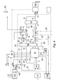
- Fig. 4 is a detailed diagrammatic view of the combustion apparatus in an oxyfuel firing mode and at full load.
- the combustion apparatus is started and shutdown in a conventional manner using air firing with transfer over to the oxyfuel mode of operation occurring at the appropriate minimum stable load combustion conditions.
- the forced draught fan air intake D1 is gradually closed whilst the stack damper D2 is throttled to enable the flue gases to be recycled to the boiler plant 10.
- substantially pure oxygen is supplied from an air separation unit/oxygen plant 150 and introduced into both the primary flue gas recirculation stream via damper D5 and the secondary flue gas recirculation stream via damper D6.
- flue gas is admitted to the carbon dioxide purification and compression plant 84 by flow balance control between the flue gas recycle damper D3 and damper D4.
- Flue gas monitoring equipment is used to provide an indication to the boiler operator of when the flue gas carbon dioxide quality meets the requirements for safe supply of this oxyfuel flue gas to the carbon dioxide purification and compression plant 84.
- a conventional coal handling system supplies raw coal along Stream 1 from the coal bunkers to milling equipment 44.
- the coal is pulverised and transported with oxyfuel flue gas along Stream 2 (primary fuel input conduit) to the combustion chamber of the boiler 10.
- Air is separated prior to the boiler's combustion system using commercially available air separation units 150 which separate the oxygen from the ambient air feed. Therefore, nitrogen is not used during oxyfuel combustion. No combustion air is supplied to the boiler system, although a degree of air ingress (Stream 29) may occur due to the balanced draught boiler plant design. Appropriate mechanical design can minimise this air ingress.
- the oxygen from the air separation unit 150 is preheated through a heat exchanger 154, using appropriate available sources of heat.
- the preheated oxygen in Stream 27 and the primary flue gas recycle in Stream 21 are mixed at a mixer 170 before entering the milling plant via Stream 22.
- the oxygen concentration in the resulting mixed Stream 22 is limited to the equivalent of air.
- the primary flue gas recycle stream (Stream 21) is delivered de-ashed, cleaned, dried and preheated with the volumetric flow rate set to meet the requirements of the milling plant and product temperature.
- the secondary flue gas recycle stream (Stream 24) is mixed at a mixer 172 with preheated oxygen in Stream 28 and fed to the boiler's combustion system via Stream 25 (secondary input conduit 50).
- the carbon dioxide in Stream 25 replaces the part of the ballasting inert bulk gas formerly provided by atmospheric nitrogen.
- the secondary flue gas recycle stream is de-ashed, cleaned and preheated.
- the secondary flue gas is supplied to attain combustion equipment performance through the delivery of stable and efficient coal combustion.
- the secondary flue gas also controls furnace combustion temperatures comparable to power generation air-fired plant and achieves rated boiler thermal performance.
- the flue gas is recirculated and split to provide primary flue gas recirculation and secondary flue gas recirculation.
- Oxygen injection is downstream of the gas-gas heaters 62 and flue gas fans due to the risk of particulate impingement on fan blades.
- the oxygen injection system is designed to promote efficient mixing of oxygen and flue gas.
- Primary oxygen mixing is upstream of the milling equipment 44.
- the oxygen concentration in the primary flue gas recirculation stream upstream of the milling plant is arranged to be approximately equivalent to the oxygen concentration in air.
- the balanced draught boiler design is capable of firing the design specified coal range throughout the entire boiler load range without operational constraints on oxyfuel firing.
- the furnace is designed with an appropriate combustion system which incorporates low NOx axial swirl pulverised fuel burners, suitable for both air and oxyfuel firing and any proportion in between, and multi-stage combustion system (overfire combustion ports) in the furnace walls for in-furnace primary NOx reduction and combustion efficiency specifications as appropriate.
- the boiler plant is designed with full control range suitable for full load operation on air or oxyfuel mode of operation and any proportion in between. The boiler plant retains full air-firing capability with appropriate emissions control plant.
- the products of combustion leave the radiant furnace and are cooled by the boiler's heating surfaces downstream.
- the oxyfuel flue gas leaving the furnace enters the boiler's convective pass where supercritical steam generated in the furnace walls is further superheated and reheated for power generation.
- An economiser is situated in the convective gas pass.
- the DeNOx unit 120 is adapted such that it can be bypassed during oxyfuel operation.
- Oxyfuel flue gas in Stream 3 is further cooled in the gas-gas heater 62 (Streams 4 and 5) which is used to preheat the incoming oxyfuel recycle flue gas in Streams 20 and 23.
- the flue gas in Stream 5 leaving the gas-gas heater 62 is de-dusted through particulate removal plant 122 before being cooled in a downstream heat recovery unit 156.
- the de-dusted and cooled flue gas in Stream 7 is fed to the induction draught fan 66 downstream.
- the flue gas Downstream of the induction draught fan 66 (Stream 8), the flue gas enters the DeSOx plant 68.
- the DeSOx plant 68 is employed to treat all of the flue gas and provide clean oxyfuel flue gas recycle so as to limit the corrosive gaseous components in the oxyfuel flue gas recycle stream to the milling equipment 44 and boiler plant 10 to concentrations no worse than those experienced during air firing.
- the cold oxyfuel flue gas Downstream of the DeSOx plant 68, the cold oxyfuel flue gas is split into two streams.
- One stream (Stream 10) provides the net oxyfuel flue gas feed stream to the carbon dioxide purification and compression plant 84.
- the remaining clean flue gas stream (Stream 11) is recycled back to the boiler system via a forced draught fan 80 and Stream 16.
- flue gas in Stream 11 is reheated, as required, through a gas-gas heater within the DeSOx plant 68.
- the flue gas in Stream 12 then passes on through the downstream fan and flue gas recirculation ductwork.
- Flue gas in Stream 11 is split to provide a primary flue gas recycle stream (Stream 17) and a secondary flue gas recycle stream (Stream 23).
- the cold oxyfuel flue gas in Stream 20 is also used to provide the tempering gas stream (Stream 26) for mill outlet temperature control and mill sealing.
- the moisture content of the oxyfuel flue gas will be at a higher level than with conventional air-firing derived flue gas due to the effect of flue gas recycle.
- the use of a wet scrubber DeSOx system if appropriate, will increase the flue gas moisture content, and the recycle flue gas will be saturated at the final temperature at which the flue gas is cooled.
- a moisture removal plant can be located either in the full flue gas stream (Stream 9) or in the primary flue gas recycle stream (Stream 20) to the gas-gas heater 62.
- the dried oxyfuel flue gas stream (Stream 20) is preheated in the gas-gas heater 62 and tempered as required (Stream 26), providing the primary flue gas recycle stream (Stream 21).
- the oxyfuel secondary flue gas recycle stream is delivered preheated (Stream 24) to the boiler's combustion system from the gas-gas heater 62. Both the primary and the secondary flue gas recycle streams are preheated with heat recovered from the hot oxyfuel flue gas exiting the boiler system along Stream 4.
- a conventional ash handling system 160 serves the ASC boiler coarse ash via Stream 30, fly ash via Stream 31 and ESP fly ash via Stream 32.
- Overall oxyfuel plant performance is optimised through process integration including recovery of low grade from the oxyfuel boiler island (Stream 35).
- Dual air/oxyfuel burners are designed to operate up to their full thermal rating for 100% air-firing or 100% oxyfuel firing or any proportion in between.
- the burners are designed to be as robust and mechanically simple as possible, offering long life and long periods of continuous operation and dramatically simplifying commissioning and operating procedures.
- Each burner includes a primary combustion stream either as primary air or oxygen enriched primary flue gas recycle provided by the primary air fans which is combined with the pulverized fuel at the mills 44. The resulting mixture is fed to the burner and delivered into the combustion chamber.
- a primary combustion stream either as primary air or oxygen enriched primary flue gas recycle provided by the primary air fans which is combined with the pulverized fuel at the mills 44. The resulting mixture is fed to the burner and delivered into the combustion chamber.
- Each burner incorporates combustion stream-proportioning dampers that enable the flow to individual burners to be balanced within the windbox, and to adjust the distribution to the combustion streams within the burner. Adjustment rods connected to the combustion stream proportioning dampers pass through the burner front plate allowing the position of the damper to be adjusted external to the burner.
- the streams pass through concentric tubes in the burner, admitting the combustion streams to the furnace at different stages of the combustion process, thereby controlling the local stoichiometry and temperatures and the formation of NOx, particularly when firing with air.
- One or more dampers on the burner proportion the quantity of the streams within each burner.
- Adjustment rods connected to the barrel damper(s) pass through the burner front plate allowing the position of the barrel damper to be adjusted during operation of the burner.
- the necessary swirl is imparted to each stream by separate swirl generators.
- Adjustment for NOx control is achieved by varying the burner stoichiometry by adjusting the proportion of combustion air or oxygen enriched flue gas recycle between the burner and over-fire combustion windboxes.
- the burner also has a core air tube through which the light-up equipment is inserted.
- Each burner is fitted, inside the core air tube, with a light fuel burner for lighting up, low load coal firing stabilization, and (optionally) partial boiler load carrying.
- a small flow of air is required down this tube to provide combustion oxygen.
- Air or oxygen enriched flue gas recycle is used to keep the core air tube free from ash build-up during service.
- the start-up burners are ignited directly by appropriate spark igniters.
- the multi-stage combustion system over-fire air/combustion ports comprise a number of separate combustion streams, such as an inner stream which is unswirled and which delivers the combustion stream to the centre of the combustion chamber, and one or more outer streams which are swirled and encourage mixing with the rising flue gases closer to the furnace walls.
- the degree of swirl and the split between the streams is controlled by simple adjustment rods and set after commissioning.
- condition of the flame from each burner may be continuously monitored by flame monitoring equipment, providing a remote indication of burner flame conditions to a main control room.
- the combustion apparatus of the invention provides full air firing capability with appropriate emission control plant.
- the balanced draught boiler island design includes full control range suitable for operation using air, oxyfuel or proportions of both.
- the low NOx pulverised fuel burners are suitable for air or oxyfuel firing or a proportion of both, and also allow multi-stage combustion.
- the gas-gas heaters 62 are also suitable for use for air and oxyfuel operation.
- the combustion apparatus of the invention covers the same range of fuels as is covered by conventional air-fired technology, particularly with respect to the sulphur and chlorine content of the coal.
- the oxyfuel flue gas is cleaned before being recycled to the milling plant 44 and boiler 10.
- DeSOx Plant 68 provides clean oxyfuel flue gas recycle, which ensures that corrosive gaseous components result in concentrations in the boiler 10 which are no worse than that experienced with air-firing.
- the total flue gas recycle stream is split into primary and secondary streams.
- the primary stream quantity is set according to the requirements of the milling plant 44.
- the secondary stream quantity is set to provide an optimum balance between the combustion equipment and furnace/boiler requirements.
- the combustion apparatus of the invention is suitable as a retrofit to existing coal-fired boiler plant or for new coal-fired boiler plant designs, whether subcritical or supercritical.
- the apparatus allows the use of conventional coal and ash handling and milling (direct or indirect) equipment.
- the apparatus can selectively and switchably be fired using air or an oxygen enriched gas.
- the gas-gas heaters are suitable for use for both 100% air operation and 100% oxyfuel operation and any proportion in between.
- the balance of oxygen required is supplied to the radiant furnace via the secondary stream and other multi-stage combustion system gas streams.
- the apparatus includes the capability to allow separate tuning of the oxygen concentrations in each stream as appropriate.
- Oxygen is supplied directly to the boiler's combustion equipment, as appropriate, other than that provided to the primary and secondary oxyfuel flue gas streams.
- Oxygen mixed with recycled flue gas is also supplied to the burners (via the secondary input conduit) and so the burners may utilise staged combustion to minimise the oxidation of nitrogen present in the coal.
- the combustion characteristics of the mixture of oxygen and flue gas are similar in some respects to that of air. It is therefore possible to switch between air firing and firing using this mixture without significantly altering the thermal characteristics from the overall combustion apparatus.
- the apparatus of the invention can vary the oxygen content during combustion which allows optimum performance regardless of the fuel used (such as low or high volatile coal).
Landscapes
- Engineering & Computer Science (AREA)
- Chemical & Material Sciences (AREA)
- Combustion & Propulsion (AREA)
- Mechanical Engineering (AREA)
- General Engineering & Computer Science (AREA)
Abstract
Description
- The present invention relates to combustion apparatus. In particular, but not exclusively, the invention relates to combustion apparatus capable of air and oxyfuel firing and utilising flue gas recirculation.
- There is a widespread desire to reduce the causes of global warming, and an increased carbon dioxide level in the atmosphere is considered to be the most dominant factor. One source of the emission of carbon dioxide to the atmosphere is the combustion of fossil fuels in power plants. One response to this is to seek to capture and store the carbon dioxide emitted during combustion.
- Carbon dioxide capture techniques are often categorised into the three groups of pre-combustion capture, post-combustion capture, and oxyfuel combustion capture. In the latter approach, near pure or pure oxygen is supplied to the boiler's combustion system (oxyfuel combustion), and also at least a portion of the carbon dioxide rich flue gas is recycled back to the boiler (flue gas recirculation). Oxyfuel combustion produces a flue gas which primarily consists of carbon dioxide and water vapour. The flue gas is not diluted with nitrogen (as occurs using air combustion) and so the carbon dioxide can be readily captured. The reduced levels of nitrogen can also reduce the formation of NOx (a term used to cover nitric oxide, nitrogen dioxide and nitrous oxide). Flue gas recirculation itself is also known to reduce the formation of NOx.
- It is desirable that this approach can be used for retrofitting existing boilers as well as for new plant designs. Also, for an existing or new boiler, it is often desirable that the boiler can selectively and switchably be fired using air or using oxygen and recycled flue gas. For instance, during start up or shut down of the boiler, air firing achieves a stable low load operation. After start up, there can be a switch to oxygen and flue gas recirculation to achieve carbon dioxide capture. It is also desirable that the boiler can operate across the full load range in both the air firing and oxyfuel mode.
- However, the combustion of a fossil fuel, such as pulverised coal, in an oxygen rich gas results in a high flame temperature, which can cause ash melting and may actually increase the formation of NOx. Conventionally, in prior art apparatus, air is still supplied to the fuel input (primary stream) of the boiler. If high levels of oxygen are supplied directly to the fuel input, there can also be premature combustion as the fuel catches fire, which is wasteful and hazardous. However, the conventional use of air again increases the levels of nitrogen present, leading to the formation of NOx. It is desirable to be able to control flame temperature while optimising, or at least maintaining, the efficiency of the boiler. It is desirable to eliminate this source of nitrogen.
- On the other hand, there are a number of disadvantages associated with supplying oxygen directly to the burner section of the boiler (the secondary stream). For instance, modern low NOx burners typically utilise staged combustion to minimise the oxidation of nitrogen present in the fuel, and a higher oxygen supply to the burners may be counter-productive in this respect. Also, the supply of oxygen directly to the burner section results in particular thermal characteristics from the overall system. It is then more difficult, or less efficient, to switch between air firing and firing using an oxygen enriched gas. It is desirable to be able to limit the oxygen content supplied to the burners. It is desirable to be able to vary the oxygen content supplied to the burners for a number of reasons, such as to optimize performance or to allow switching between air firing and firing using an oxygen enriched gas.
- Furthermore, the fuel used can significantly affect the performance of the boiler. For instance, when using very low volatile coal, it is desirable to optimise the oxygen content to assist ignition of the volatile matter. It is therefore desirable to vary the oxygen content of the fuel stream.
- According to a first aspect of the present invention, there is provided a combustion apparatus comprising:
- a combustion chamber;
- a primary fuel input conduit for supplying fuel to the combustion chamber;
- a secondary input conduit for supplying combustion gas to the combustion chamber; and
- combustion gas supply means,
- wherein the combustion gas supply means is adapted to switchably supply either air or an oxygen rich gas to at least the secondary input conduit.
- The term "oxygen rich gas" is intended to cover a quantity of gas having a proportion of oxygen which is greater than 21 % by volume and including pure oxygen.
- Preferably the combustion gas supply means is adapted to supply substantially pure oxygen.
- Preferably the combustion gas supply means is adapted to selectively supply a mixture of the oxygen rich gas and a second gas to the secondary input conduit. Preferably the second gas does not include air. Preferably the second gas does not include nitrogen. The mixture flowing within the secondary input conduit may have any proportion of oxygen and may be less than 21 % by volume.
- Preferably the combustion gas supply means is adapted to switchably supply either air or the oxygen rich gas to both of the primary fuel input conduit and the secondary input conduit.
- Preferably the combustion gas supply means includes varying means for varying the proportion of air or oxygen rich gas supplied to one or both of the primary fuel input conduit and the secondary input conduit.
- Preferably the combustion apparatus comprises a boiler for generating steam.
- Preferably the fuel used is coal, most preferably pulverised coal. Preferably the combustion gas supply means is adapted to supply either air or the oxygen rich gas to the primary fuel input conduit such that the air or oxygen rich gas at least assists in transporting the fuel to the combustion chamber. Preferably the combustion gas supply means includes one or more fan units.
- Preferably the secondary input conduit supplies air or oxygen rich gas to one or more burners provided at the combustion chamber.
- The combustion apparatus may include one or more tertiary input conduits fluidly connected to the combustion gas supply means for supplying air or the oxygen rich gas directly to the combustion apparatus and for example directly to the combustion chamber or to another component of the combustion apparatus. For example one or more tertiary input conduits supply air or oxygen rich gas to one or more burners provided at the combustion chamber.
- Preferably the combustion apparatus includes a flue gas recirculation conduit. Preferably the flue gas recirculation conduit is fluidly connected to at least one of the primary fuel input conduit and the secondary input conduit such that a mixture of air or the oxygen rich gas and flue gas is supplied to the combustion chamber. Preferably the flue gas recirculation conduit is fluidly connected to both of the primary fuel input conduit and the secondary input conduit.
- An embodiment of the present invention will now be described, by way of example only, with reference to the accompanying drawings, in which:
-
Fig. 1 is a simplified diagrammatic view of a combustion apparatus according to the invention; -
Fig. 2 is a sectional side view of a burner of the combustion apparatus ofFig. 1 ; -
Fig. 3 is a more detailed diagrammatic view of a combustion apparatus according to the invention in an air fired mode; and -
Fig. 4 is a diagrammatic view of the combustion apparatus ofFig. 3 in an oxyfuel fired mode. -
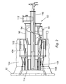
Fig. 1 shows a combustion apparatus including an air and oxyfuel firedboiler 10 for generating steam which is used to operateturbines 20 for producing electric power from generatingapparatus 30. - The
boiler 10 defines acombustion chamber 15. The boiler has a primaryfuel input conduit 40 for supplying coal from afuel store 42 via a pulverisingmill 44 to theboiler 10. Theboiler 10 also has asecondary input conduit 50 for supplying a combustion gas to a number ofburners 52 fitted to theboiler 10. - The combustion apparatus includes combustion gas supply means which includes an
oxygen supply 70 and anair supply 71. The combustion gas supply means is controllable to switch between supplying either air or an oxygen rich gas in the form of pure oxygen.Conduits oxygen supply 70 of the combustion gas supply means to both of the primaryfuel input conduit 40 and thesecondary input conduit 50. Although these conduits are fluidly connected, they may not be directly or physically connected. For instance, in the example ofFig. 1 ,conduit 74 is directly connected to a conduit leading to themill 44, which in turn is connected to the primaryfuel input conduit 40. - The combustion gas supply means also includes a
valve 73 which is controllable to vary the proportion of oxygen which is supplied to the primaryfuel input conduit 40 and thesecondary input conduit 50. For instance, 70% of the available combustion gas may be supplied to the primaryfuel input conduit secondary input conduit fuel input conduit secondary input conduit 50. - The combustion apparatus also includes a flue
gas recirculation system 60. Flue gas is drawn through aheater 62 and electrostatic precipitator (ESP) 64 using afan 66. The flue gas is de-ashed by theESP 64. The clean flue gas then passes to a flue gas desulphurisation (FGD)unit 68 and then to a carbon dioxide purification andcompression unit 84. - A large proportion of the flue gas is recycled back through the
heater 62, drawn by anotherfan 80, while the remainder bypasses theheater 62 to provide a tempering stream. A proportion of the flue gas then flows to thesecondary input conduit 50, while the remainder is passed to the primaryfuel input conduit 40 via themill 44. In the air firing mode or a transition mode (but not the oxyfuel mode), a proportion of the flue gas up to 100% is not recycled but is emitted to atmosphere via astack 82. The proportion of flue gas which is recycled through theheater 62 then passes to thesecondary input conduit 50. - The flue
gas recirculation system 60 is therefore fluidly connected to thesecondary input conduit 50 such that flue gas is supplied to theboiler 10. Thesystem 60 is also fluidly connected to the primaryfuel input conduit 40. - When the combustion gas supply means is switched to supplying oxygen, the oxygen is supplied to the primary
fuel input conduit 40 which is fluidly connected to a conduit of the fluegas recirculation system 60 such that a mixture of flue gas and oxygen are supplied to themill 44 using afan 76. This mixture transports the pulverised coal to theboiler 10. The combustion gas supply means also supplies oxygen to thesecondary input conduit 50 such that a mixture of oxygen and flue gas is supplied to theboiler 10. The supply of oxygen to both the primaryfuel input conduit 40 and thesecondary input conduit 50 occurs downstream of theheater 62. - A
suitable burner 52 fitted to aboiler wall 12 is shown inFig. 2 . Full burner thermal rating is achievable with pulverised fuel air firing and with pulverised fuel oxyfuel firing. Eachburner 52 has five co-axially arranged tubular partitions defining annular passages for one, or a mixture, of fuel, oxygen, flue gas, and air. - Each
burner 52 has aprimary tube 90 which is fluidly connected to the primaryfuel input conduit 40. A mixture of fuel, recycled flue gas and oxygen is supplied to ascroll plate 94 of theprimary tube 90 via a tangential connection 92 (or air is supplied during air firing). - Each
burner 52 also has asecondary tube 100 which is fluidly connected to thesecondary input conduit 50. A mixture of recycled flue gas and oxygen is supplied toapertures 102 provided in thesecondary tube 100 from awind box 104 surrounding the burner 52 (or air is supplied during air firing). - Each
burner 52 includes twotertiary tubes core tube 110 is provided, which includes aradial connection 112. These tubes may be fluidly connected to one or both of the combustion gas supply means and the fluegas recirculation system 60. - In operation, fuel within the
primary tube 90 is given an axial and a circumferential momentum by thescroll plate 94. The flow is discharged past alip 114 as a vigorously eddying flow which ignites at thelip 114 defining an initial combustion region. Reducing conditions prevail within this region such that there is minimal oxidation of the nitrogen in the fuel. The amount of oxygen in thecore tube 110 is also limited to maintain these conditions. - Flow from the secondary 100 and tertiary 106, 108 tubes forms an envelope around the initial combustion region so that combustion of the fuel is completed downstream under oxidising conditions.
-
Fig. 3 is a more detailed diagrammatic view of a combustion apparatus according to the invention which is in an air firing mode and at full load. - A conventional
coal handling system 42 supplies raw coal along Stream 1 from the coal bunkers to millingequipment 44 where coal is pulverised and transported with air alongStream 2, which is the primary fuel input conduit, to the combustion chamber of theboiler 10. - The combustion air and flue gas streams are designed for balanced draught operation. The combustion air system includes forced
draught fans 80,primary air fans 132 and gas-gas heaters 62 for heating the combustion air. From downstream of the gas-gas heaters 62, heated air is split into primary air and secondary air. In this mode, the heater is a gas-air heater. - Primary air is transported along
Stream 22 to themilling equipment 44 for coal drying and pulverised fuel transportation along Stream 2 (the primary fuel input conduit). Cold primary air (Stream 26) is used to provide the tempering air stream for mill outlet temperature control. - The secondary air travelling along Stream 25 (the secondary input conduit) is supplied to the combustion chamber of the
boiler 10. The secondary air splits into windbox air and overfire air (a multi-stage combustion system incorporating overfire air ports). The windbox air is supplied directly to the burners (not shown inFig 3 ). - As the boiler plant design is based on a balanced draught boiler design, it is capable of firing the design specified coal range throughout the entire boiler load range without operational constraints on air firing. The balanced draught furnace is designed with an appropriate combustion system to meet in-furnace primary NOx limits and combustion efficiency specifications as appropriate. To reduce pollutant constituents of the flue gas to below allowable emission limits, the boiler island plant employs appropriate emissions control plant located in the flue gas downstream. This plant comprises
deNOx plant 120, particulate andmercury removal 122 anddeSOx plant 68. - The products of combustion leave the furnace and are cooled by the boiler's heating surfaces downstream. The flue gas leaving the furnace enters the boiler's convective pass where steam generated in the furnace walls is further superheated and reheated for power generation. The boiler unit comprises a radiant furnace and radiant and convective heating surfaces. The furnace/boiler walls comprise gas-tight membrane surfaces to minimise air ingress. Heating surface arrangements are provided which avoid inadmissible slagging or fouling and inadmissible steam flow and temperature. Appropriate flow velocities are selected to ensure both adequate cooling of the water/steam side and no significant erosion potential on the flue gas side.
- Downstream of the boiler convective pass, incorporating
DeNOx plant 120, the flue gas flowing alongStream 4 is cooled in a gas-gas heater 62, as used to preheat the incoming cold combustion air inStream 16. The gas-gas heater 62, such as a 3-stream/tri-sector design, is suitable for use during both air and oxyfuel operation, and any proportion in between. The flue gas leaving the gas-gas heater 62 atStream 5 is de-dusted throughparticulate removal plant 122 where the de-dusted gas (Stream 7) is fed to the downstreaminduction draught fan 66 andDeSOx plant 68. The outlet from the DeSOx plant 68 (Stream 12) then exhausts to the flue stack viaStream 13,or alternatively may be exhausted directly to a cooling tower without the need for reheat. -
Fig. 4 is a detailed diagrammatic view of the combustion apparatus in an oxyfuel firing mode and at full load. - The combustion apparatus is started and shutdown in a conventional manner using air firing with transfer over to the oxyfuel mode of operation occurring at the appropriate minimum stable load combustion conditions. At this load condition, the forced draught fan air intake D1 is gradually closed whilst the stack damper D2 is throttled to enable the flue gases to be recycled to the
boiler plant 10. Simultaneously, substantially pure oxygen is supplied from an air separation unit/oxygen plant 150 and introduced into both the primary flue gas recirculation stream via damper D5 and the secondary flue gas recirculation stream via damper D6. - When appropriate carbon dioxide levels in the flue gas have been reached, flue gas is admitted to the carbon dioxide purification and
compression plant 84 by flow balance control between the flue gas recycle damper D3 and damper D4. Flue gas monitoring equipment is used to provide an indication to the boiler operator of when the flue gas carbon dioxide quality meets the requirements for safe supply of this oxyfuel flue gas to the carbon dioxide purification andcompression plant 84. - As before, a conventional coal handling system supplies raw coal along Stream 1 from the coal bunkers to milling
equipment 44. The coal is pulverised and transported with oxyfuel flue gas along Stream 2 (primary fuel input conduit) to the combustion chamber of theboiler 10. - Air is separated prior to the boiler's combustion system using commercially available
air separation units 150 which separate the oxygen from the ambient air feed. Therefore, nitrogen is not used during oxyfuel combustion. No combustion air is supplied to the boiler system, although a degree of air ingress (Stream 29) may occur due to the balanced draught boiler plant design. Appropriate mechanical design can minimise this air ingress. - The oxygen from the
air separation unit 150 is preheated through aheat exchanger 154, using appropriate available sources of heat. The preheated oxygen inStream 27 and the primary flue gas recycle inStream 21 are mixed at amixer 170 before entering the milling plant viaStream 22. The oxygen concentration in the resultingmixed Stream 22 is limited to the equivalent of air. The primary flue gas recycle stream (Stream 21) is delivered de-ashed, cleaned, dried and preheated with the volumetric flow rate set to meet the requirements of the milling plant and product temperature. - The secondary flue gas recycle stream (Stream 24) is mixed at a
mixer 172 with preheated oxygen inStream 28 and fed to the boiler's combustion system via Stream 25 (secondary input conduit 50). The carbon dioxide inStream 25 replaces the part of the ballasting inert bulk gas formerly provided by atmospheric nitrogen. The secondary flue gas recycle stream is de-ashed, cleaned and preheated. The secondary flue gas is supplied to attain combustion equipment performance through the delivery of stable and efficient coal combustion. The secondary flue gas also controls furnace combustion temperatures comparable to power generation air-fired plant and achieves rated boiler thermal performance. The flue gas is recirculated and split to provide primary flue gas recirculation and secondary flue gas recirculation. Oxygen injection is downstream of the gas-gas heaters 62 and flue gas fans due to the risk of particulate impingement on fan blades. The oxygen injection system is designed to promote efficient mixing of oxygen and flue gas. Primary oxygen mixing is upstream of themilling equipment 44. The oxygen concentration in the primary flue gas recirculation stream upstream of the milling plant is arranged to be approximately equivalent to the oxygen concentration in air. - The balanced draught boiler design is capable of firing the design specified coal range throughout the entire boiler load range without operational constraints on oxyfuel firing. The furnace is designed with an appropriate combustion system which incorporates low NOx axial swirl pulverised fuel burners, suitable for both air and oxyfuel firing and any proportion in between, and multi-stage combustion system (overfire combustion ports) in the furnace walls for in-furnace primary NOx reduction and combustion efficiency specifications as appropriate. The boiler plant is designed with full control range suitable for full load operation on air or oxyfuel mode of operation and any proportion in between. The boiler plant retains full air-firing capability with appropriate emissions control plant.
- The products of combustion leave the radiant furnace and are cooled by the boiler's heating surfaces downstream. The oxyfuel flue gas leaving the furnace enters the boiler's convective pass where supercritical steam generated in the furnace walls is further superheated and reheated for power generation. An economiser is situated in the convective gas pass. The
DeNOx unit 120 is adapted such that it can be bypassed during oxyfuel operation. Oxyfuel flue gas in Stream 3 is further cooled in the gas-gas heater 62 (Streams 4 and 5) which is used to preheat the incoming oxyfuel recycle flue gas inStreams Stream 5 leaving the gas-gas heater 62 is de-dusted throughparticulate removal plant 122 before being cooled in a downstreamheat recovery unit 156. The de-dusted and cooled flue gas in Stream 7 is fed to theinduction draught fan 66 downstream. - Downstream of the induction draught fan 66 (Stream 8), the flue gas enters the
DeSOx plant 68. TheDeSOx plant 68 is employed to treat all of the flue gas and provide clean oxyfuel flue gas recycle so as to limit the corrosive gaseous components in the oxyfuel flue gas recycle stream to themilling equipment 44 andboiler plant 10 to concentrations no worse than those experienced during air firing. - Downstream of the
DeSOx plant 68, the cold oxyfuel flue gas is split into two streams. One stream (Stream 10) provides the net oxyfuel flue gas feed stream to the carbon dioxide purification andcompression plant 84. The remaining clean flue gas stream (Stream 11) is recycled back to the boiler system via a forceddraught fan 80 andStream 16. After this splitting, flue gas inStream 11 is reheated, as required, through a gas-gas heater within theDeSOx plant 68. The flue gas inStream 12 then passes on through the downstream fan and flue gas recirculation ductwork. - Flue gas in
Stream 11 is split to provide a primary flue gas recycle stream (Stream 17) and a secondary flue gas recycle stream (Stream 23). The cold oxyfuel flue gas inStream 20 is also used to provide the tempering gas stream (Stream 26) for mill outlet temperature control and mill sealing. The moisture content of the oxyfuel flue gas will be at a higher level than with conventional air-firing derived flue gas due to the effect of flue gas recycle. In addition, the use of a wet scrubber DeSOx system, if appropriate, will increase the flue gas moisture content, and the recycle flue gas will be saturated at the final temperature at which the flue gas is cooled. As appropriate, a moisture removal plant can be located either in the full flue gas stream (Stream 9) or in the primary flue gas recycle stream (Stream 20) to the gas-gas heater 62. The dried oxyfuel flue gas stream (Stream 20) is preheated in the gas-gas heater 62 and tempered as required (Stream 26), providing the primary flue gas recycle stream (Stream 21). - The oxyfuel secondary flue gas recycle stream is delivered preheated (Stream 24) to the boiler's combustion system from the gas-
gas heater 62. Both the primary and the secondary flue gas recycle streams are preheated with heat recovered from the hot oxyfuel flue gas exiting the boiler system alongStream 4. - A conventional
ash handling system 160 serves the ASC boiler coarse ash viaStream 30, fly ash viaStream 31 and ESP fly ash viaStream 32. Overall oxyfuel plant performance is optimised through process integration including recovery of low grade from the oxyfuel boiler island (Stream 35). - Dual air/oxyfuel burners are designed to operate up to their full thermal rating for 100% air-firing or 100% oxyfuel firing or any proportion in between. The burners are designed to be as robust and mechanically simple as possible, offering long life and long periods of continuous operation and dramatically simplifying commissioning and operating procedures.
- Each burner includes a primary combustion stream either as primary air or oxygen enriched primary flue gas recycle provided by the primary air fans which is combined with the pulverized fuel at the
mills 44. The resulting mixture is fed to the burner and delivered into the combustion chamber. - Additional oxygen for completion of combustion is supplied either as windbox air or oxygen enriched flue gas recycle via one or more streams. Each burner incorporates combustion stream-proportioning dampers that enable the flow to individual burners to be balanced within the windbox, and to adjust the distribution to the combustion streams within the burner. Adjustment rods connected to the combustion stream proportioning dampers pass through the burner front plate allowing the position of the damper to be adjusted external to the burner.
- The streams pass through concentric tubes in the burner, admitting the combustion streams to the furnace at different stages of the combustion process, thereby controlling the local stoichiometry and temperatures and the formation of NOx, particularly when firing with air. One or more dampers on the burner proportion the quantity of the streams within each burner. Adjustment rods connected to the barrel damper(s) pass through the burner front plate allowing the position of the barrel damper to be adjusted during operation of the burner. The necessary swirl is imparted to each stream by separate swirl generators. Adjustment for NOx control is achieved by varying the burner stoichiometry by adjusting the proportion of combustion air or oxygen enriched flue gas recycle between the burner and over-fire combustion windboxes.
- The burner also has a core air tube through which the light-up equipment is inserted. Each burner is fitted, inside the core air tube, with a light fuel burner for lighting up, low load coal firing stabilization, and (optionally) partial boiler load carrying. During light-up, a small flow of air is required down this tube to provide combustion oxygen. Air or oxygen enriched flue gas recycle, is used to keep the core air tube free from ash build-up during service. The start-up burners are ignited directly by appropriate spark igniters.
- The multi-stage combustion system over-fire air/combustion ports comprise a number of separate combustion streams, such as an inner stream which is unswirled and which delivers the combustion stream to the centre of the combustion chamber, and one or more outer streams which are swirled and encourage mixing with the rising flue gases closer to the furnace walls. The degree of swirl and the split between the streams is controlled by simple adjustment rods and set after commissioning.
- During boiler operation, the condition of the flame from each burner may be continuously monitored by flame monitoring equipment, providing a remote indication of burner flame conditions to a main control room.
- The combustion apparatus of the invention provides full air firing capability with appropriate emission control plant. The balanced draught boiler island design includes full control range suitable for operation using air, oxyfuel or proportions of both. The low NOx pulverised fuel burners are suitable for air or oxyfuel firing or a proportion of both, and also allow multi-stage combustion. The gas-
gas heaters 62 are also suitable for use for air and oxyfuel operation. - The combustion apparatus of the invention covers the same range of fuels as is covered by conventional air-fired technology, particularly with respect to the sulphur and chlorine content of the coal. In order to ensure that the oxyfuel boiler plant is no more susceptible to high temperature corrosion due to increased concentrations of SO2 (and SO3) and HCI, the oxyfuel flue gas is cleaned before being recycled to the
milling plant 44 andboiler 10.DeSOx Plant 68 provides clean oxyfuel flue gas recycle, which ensures that corrosive gaseous components result in concentrations in theboiler 10 which are no worse than that experienced with air-firing. - The total flue gas recycle stream is split into primary and secondary streams. The primary stream quantity is set according to the requirements of the
milling plant 44. The secondary stream quantity is set to provide an optimum balance between the combustion equipment and furnace/boiler requirements. - The combustion apparatus of the invention is suitable as a retrofit to existing coal-fired boiler plant or for new coal-fired boiler plant designs, whether subcritical or supercritical. The apparatus allows the use of conventional coal and ash handling and milling (direct or indirect) equipment. The apparatus can selectively and switchably be fired using air or an oxygen enriched gas.
- The gas-gas heaters are suitable for use for both 100% air operation and 100% oxyfuel operation and any proportion in between.
- In addition to the primary flue gas recycle, the balance of oxygen required is supplied to the radiant furnace via the secondary stream and other multi-stage combustion system gas streams. The apparatus includes the capability to allow separate tuning of the oxygen concentrations in each stream as appropriate. Oxygen is supplied directly to the boiler's combustion equipment, as appropriate, other than that provided to the primary and secondary oxyfuel flue gas streams. Oxygen mixed with recycled flue gas is also supplied to the burners (via the secondary input conduit) and so the burners may utilise staged combustion to minimise the oxidation of nitrogen present in the coal.
- Since the coal is supplied to the
boiler 10 using a mixture of oxygen and flue gas, ash melting and the formation of NOx and carbon monoxide are substantially reduced. The reduction of premature combustion of the coal increases the efficiency of the combustion apparatus. - The combustion characteristics of the mixture of oxygen and flue gas are similar in some respects to that of air. It is therefore possible to switch between air firing and firing using this mixture without significantly altering the thermal characteristics from the overall combustion apparatus.
- The apparatus of the invention can vary the oxygen content during combustion which allows optimum performance regardless of the fuel used (such as low or high volatile coal).
- Various modifications and improvements can be made without departing from the scope of the present invention.
Claims (16)
- A combustion apparatus comprising:a combustion chamber (15);a primary fuel input conduit (40) for supplying a fuel to the combustion chamber;a secondary input conduit (50) for supplying a combustion gas to the combustion chamber; andcombustion gas supply means (70, 71, 72, 73, 74, 76),characterised in that the combustion gas supply means is adapted to switchably supply one of air and an oxygen rich gas to at least the secondary input conduit.
- A combustion apparatus as claimed in Claim 1, wherein the combustion gas supply means is adapted to supply substantially pure oxygen.
- A combustion apparatus as claimed in Claim 1, wherein the combustion gas supply means is adapted to selectively supply a mixture of the oxygen rich gas and a second gas to the secondary input conduit.
- A combustion apparatus as claimed in Claim 3, wherein the second gas does not include air.
- A combustion apparatus as claimed in Claim 3 or 4, wherein the second gas does not include nitrogen.
- A combustion apparatus as claimed in one of Claims 3 to 5, wherein the second gas is recirculated flue gas.
- A combustion apparatus as claimed in any preceding claim, wherein the combustion gas supply means is adapted to switchably supply one of air and the oxygen rich gas to both of the primary fuel input conduit and the secondary input conduit.
- A combustion apparatus as claimed in any preceding claim, wherein the combustion gas supply means includes varying means (73) for varying a proportion of one of air and oxygen rich gas supplied to at least one of the primary fuel input conduit (40) and the secondary input conduit (50).
- A combustion apparatus as claimed in Claim 8, wherein the varying means comprises a valve (73).
- A combustion apparatus as claimed in any preceding claim, wherein the combustion apparatus comprises a boiler (10) for generating steam.
- A combustion apparatus as claimed in any preceding claim, wherein the fuel used is pulverised coal.
- A combustion apparatus as claimed in any preceding claim, wherein the combustion gas supply means is adapted to supply one of air and the oxygen rich gas to the primary fuel input conduit (40) such that one of air and the oxygen rich gas at least assists in transporting the fuel to the combustion chamber (15).
- A combustion apparatus as claimed in any preceding claim, wherein the secondary input conduit (50) supplies one of air and oxygen rich gas to at least one burner (52) provided at the combustion chamber.
- A combustion apparatus as claimed in any preceding claim, including at least one tertiary input conduit fluidly connected to the combustion gas supply means for supplying one of air and the oxygen rich gas directly to at least one of the combustion apparatus and another component of the combustion apparatus.
- A combustion apparatus as claimed in any preceding claim, including a flue gas recirculation conduit (60) fluidly connected to at least one of the primary fuel input conduit and the secondary input conduit such that a mixture of flue gas and one of air and the oxygen rich gas and is supplied to the combustion chamber.
- A combustion apparatus as claimed in Claim 15, wherein the flue gas recirculation conduit is fluidly connected to both of the primary fuel input conduit and the secondary input conduit.
Priority Applications (1)
| Application Number | Priority Date | Filing Date | Title |
|---|---|---|---|
| PL08156300T PL1992876T3 (en) | 2007-05-15 | 2008-05-15 | Combustion Apparatus |
Applications Claiming Priority (1)
| Application Number | Priority Date | Filing Date | Title |
|---|---|---|---|
| US11/803,697 US9651253B2 (en) | 2007-05-15 | 2007-05-15 | Combustion apparatus |
Publications (3)
| Publication Number | Publication Date |
|---|---|
| EP1992876A2 true EP1992876A2 (en) | 2008-11-19 |
| EP1992876A3 EP1992876A3 (en) | 2011-09-14 |
| EP1992876B1 EP1992876B1 (en) | 2015-09-23 |
Family
ID=39642870
Family Applications (1)
| Application Number | Title | Priority Date | Filing Date |
|---|---|---|---|
| EP08156300.9A Revoked EP1992876B1 (en) | 2007-05-15 | 2008-05-15 | Combustion Apparatus |
Country Status (5)
| Country | Link |
|---|---|
| US (1) | US9651253B2 (en) |
| EP (1) | EP1992876B1 (en) |
| DK (1) | DK1992876T3 (en) |
| ES (1) | ES2555521T3 (en) |
| PL (1) | PL1992876T3 (en) |
Cited By (7)
| Publication number | Priority date | Publication date | Assignee | Title |
|---|---|---|---|---|
| EP2116765A2 (en) * | 2008-05-07 | 2009-11-11 | Hitachi, Ltd. | Oxyfuel boiler system and method of retrofit of air fired boiler to oxyfuel boiler |
| WO2011010161A1 (en) * | 2009-07-23 | 2011-01-27 | Doosan Power Systems Limited | Combustion apparatus |
| WO2011148298A3 (en) * | 2010-05-28 | 2013-05-16 | Foster Wheeler North America Corp. | Method of controlling a boiler plant during switchover from air-combustion to oxygen-combustion |
| EP2706298A1 (en) | 2012-09-05 | 2014-03-12 | L'air Liquide, Societe Anonyme Pour L'etude Et L'exploitation Des Procedes Georges Claude | Process and apparatus for providing an oxygen rich gas to at least two oxygen rich gas consuming units |
| EP2314920A3 (en) * | 2009-10-22 | 2014-11-26 | Mitsubishi Hitachi Power Systems, Ltd. | Retrofit method for pulverized coal boiler |
| EP2309181B1 (en) | 2009-09-30 | 2015-08-12 | Mitsubishi Hitachi Power Systems, Ltd. | Oxyfuel combustion boiler plant and operation method of oxyfuel combustion boiler plant |
| CN108019928A (en) * | 2017-11-29 | 2018-05-11 | 北京科技大学 | A kind of oxygen-enriched combusting dual chamber steam generator system |
Families Citing this family (23)
| Publication number | Priority date | Publication date | Assignee | Title |
|---|---|---|---|---|
| US8230796B2 (en) * | 2008-02-27 | 2012-07-31 | Andrus Jr Herbert E | Air-fired CO2 capture ready circulating fluidized bed steam generators |
| EP2251596B1 (en) * | 2008-03-06 | 2016-08-03 | IHI Corporation | Method and facility for feeding carbon dioxide to oxyfuel combustion boiler |
| CN102016419B (en) * | 2008-03-06 | 2013-02-06 | 株式会社Ihi | Method of controlling exhaust gas in oxygen combustion boiler and apparatus therefor |
| AU2008352212C1 (en) * | 2008-03-06 | 2012-11-29 | Electric Power Development Co., Ltd. | Method and apparatus of controlling oxygen supply in oxyfuel combustion boiler |
| US8453585B2 (en) * | 2008-04-14 | 2013-06-04 | Babcock & Wilcox Power Generation Group, Inc. | Oxy-combustion coal fired boiler and method of transitioning between air and oxygen firing |
| US20090297993A1 (en) * | 2008-05-30 | 2009-12-03 | Foster Wheeler Energia Oy | Method of and System For Generating Power By Oxyfuel Combustion |
| US20090293782A1 (en) * | 2008-05-30 | 2009-12-03 | Foster Wheeler Energia Oy | Method of and system for generating power by oxyfuel combustion |
| JP5174618B2 (en) * | 2008-10-31 | 2013-04-03 | 株式会社日立製作所 | Oxyfuel combustion boiler system and control method for oxygen combustion boiler system |
| JP4920051B2 (en) * | 2009-02-25 | 2012-04-18 | 株式会社日立製作所 | Oxyfuel combustion boiler plant and operation method of oxygen combustion boiler plant |
| JP5417068B2 (en) * | 2009-07-14 | 2014-02-12 | 株式会社日立製作所 | Oxyfuel boiler and control method for oxygen fired boiler |
| JP4896194B2 (en) * | 2009-09-30 | 2012-03-14 | 株式会社日立製作所 | Oxyfuel boiler plant |
| JP2012088016A (en) * | 2010-10-22 | 2012-05-10 | Babcock Hitachi Kk | Oxygen combustion type boiler and method of operating the same |
| JP2012093002A (en) * | 2010-10-25 | 2012-05-17 | Babcock Hitachi Kk | Boiler system and operation method therefor |
| JP2014500471A (en) * | 2010-11-16 | 2014-01-09 | アルストム テクノロジー リミテッド | Apparatus and method for controlling thermal performance of an oxyfuel boiler |
| US20120208138A1 (en) * | 2011-02-16 | 2012-08-16 | Detroit Radiant Products Company | Radiant heating assembly and method of operating the radiant heating assembly |
| US8707877B2 (en) * | 2011-06-05 | 2014-04-29 | L'air Liquide, Societe Anonyme Pour L'etude Et L'exploitation Des Procedes Georges Claude | Solid fuel and oxygen combustion with low NOx and efficient burnout |
| JP5724695B2 (en) * | 2011-07-07 | 2015-05-27 | 株式会社Ihi | Hot air fired boiler system |
| US20140041394A1 (en) * | 2012-03-01 | 2014-02-13 | Stevan Jovanovic | Integration of power generation and post combustion capture plants |
| WO2014058381A1 (en) * | 2012-10-11 | 2014-04-17 | Ecomb Ab (Publ) | Supply device for a combustion chamber |
| JP6471485B2 (en) | 2014-12-16 | 2019-02-20 | 株式会社Ihi | Dedusting device inlet temperature control method and apparatus for oxyfuel boiler equipment |
| EP3415587B1 (en) * | 2017-06-16 | 2020-07-29 | Technip France | Cracking furnace system and method for cracking hydrocarbon feedstock therein |
| WO2023237496A1 (en) * | 2022-06-09 | 2023-12-14 | Carbodown | Combustion system able to operate with recycling of the combustion gas |
| FR3136518A1 (en) * | 2022-06-09 | 2023-12-15 | Starklab | COMBUSTION SYSTEM CAPABLE OF OPERATING IN OXYCOMBUSTION WITH RECYCLING OF COMBUSTION GAS AND IN CONVENTIONAL COMBUSTION WITH AIR AS AN OXIDIZER |
Citations (4)
| Publication number | Priority date | Publication date | Assignee | Title |
|---|---|---|---|---|
| WO2000012767A1 (en) * | 1998-08-28 | 2000-03-09 | Voest-Alpine Industrieanlagenbau Gmbh | Method for producing a metal melt and corresponding multfunction lance |
| EP1327823A2 (en) * | 2002-01-08 | 2003-07-16 | The Boc Group, Inc. | Oxy-fuel combustion process |
| GB2427261A (en) * | 2005-06-17 | 2006-12-20 | Laidlaw Drew Ltd | Fuel Injector for a Glass Melting Furnace |
| WO2007126980A2 (en) * | 2006-04-03 | 2007-11-08 | Praxair Technology, Inc. | Integration of oxy-fuel and air-fuel combustion |
Family Cites Families (46)
| Publication number | Priority date | Publication date | Assignee | Title |
|---|---|---|---|---|
| US2074504A (en) * | 1933-06-12 | 1937-03-23 | William H Fitch | Powdered coal furnace |
| US2072845A (en) * | 1933-11-18 | 1937-03-09 | Benolt Francois Philip Charles | Apparatus for spraying pulverized materials |
| US3356075A (en) * | 1965-10-12 | 1967-12-05 | Combustion Eng | Method of pulverized coal firing a steam generator and controlling steam temperature |
| US3731495A (en) * | 1970-12-28 | 1973-05-08 | Union Carbide Corp | Process of and apparatus for air separation with nitrogen quenched power turbine |
| US3727562A (en) * | 1971-12-13 | 1973-04-17 | Lummus Co | Three-stage combustion |
| US3894834A (en) * | 1973-10-17 | 1975-07-15 | Airco Inc | Ignition and flame stabilization system for coal-air furnace |
| US4052138A (en) * | 1976-03-08 | 1977-10-04 | Gieck Joseph F | Method of firing coal boiler to produce secondary fuel gas |
| US4206712A (en) * | 1978-06-29 | 1980-06-10 | Foster Wheeler Energy Corporation | Fuel-staging coal burner |
| DE3331989A1 (en) * | 1983-09-05 | 1985-04-04 | L. & C. Steinmüller GmbH, 5270 Gummersbach | METHOD FOR REDUCING NO (DOWN ARROW) X (DOWN ARROW) EMISSIONS FROM THE COMBUSTION OF NITROGENOUS FUELS |
| US4909727A (en) * | 1987-03-04 | 1990-03-20 | Combustion Tec, Inc. | Oxygen enriched continuous combustion in a regenerative furance |
| US4863371A (en) * | 1988-06-03 | 1989-09-05 | Union Carbide Corporation | Low NOx high efficiency combustion process |
| US5545031A (en) * | 1994-12-30 | 1996-08-13 | Combustion Tec, Inc. | Method and apparatus for injecting fuel and oxidant into a combustion burner |
| US5567141A (en) * | 1994-12-30 | 1996-10-22 | Combustion Tec, Inc. | Oxy-liquid fuel combustion process and apparatus |
| US5743723A (en) * | 1995-09-15 | 1998-04-28 | American Air Liquide, Inc. | Oxy-fuel burner having coaxial fuel and oxidant outlets |
| US5724901A (en) * | 1995-11-02 | 1998-03-10 | Gaz Metropolitan And Company Limited | Oxygen-enriched gas burner for incinerating waste materials |
| US6071116A (en) * | 1997-04-15 | 2000-06-06 | American Air Liquide, Inc. | Heat recovery apparatus and methods of use |
| US5888272A (en) * | 1997-06-05 | 1999-03-30 | Praxair Technology, Inc. | Process for enriched combustion using solid electrolyte ionic conductor systems |
| US6149714A (en) * | 1997-06-05 | 2000-11-21 | Praxair Technology, Inc. | Process for enriched combustion using solid electrolyte ionic conductor systems |
| US5855648A (en) * | 1997-06-05 | 1999-01-05 | Praxair Technology, Inc. | Solid electrolyte system for use with furnaces |
| US5803725A (en) * | 1997-06-13 | 1998-09-08 | Horn; Wallace E. | Triple-mix surface-mix burner |
| US5921771A (en) * | 1998-01-06 | 1999-07-13 | Praxair Technology, Inc. | Regenerative oxygen preheat process for oxy-fuel fired furnaces |
| FR2781039B1 (en) * | 1998-07-08 | 2000-09-22 | Air Liquide | PROCESS FOR COMBUSTING FUEL WITH OXYGEN-RICH FUEL |
| US6113389A (en) * | 1999-06-01 | 2000-09-05 | American Air Liquide, Inc. | Method and system for increasing the efficiency and productivity of a high temperature furnace |
| AU737544B2 (en) * | 1999-10-18 | 2001-08-23 | Air Products And Chemicals Inc. | Method and apparatus for backing-up oxy fuel combustion with air-fuel combustion |
| US6519973B1 (en) * | 2000-03-23 | 2003-02-18 | Air Products And Chemicals, Inc. | Glass melting process and furnace therefor with oxy-fuel combustion over melting zone and air-fuel combustion over fining zone |
| US6382958B1 (en) * | 2000-07-12 | 2002-05-07 | Praxair Technology, Inc. | Air separation method and system for producing oxygen to support combustion in a heat consuming device |
| US6394043B1 (en) * | 2000-12-19 | 2002-05-28 | Praxair Technology, Inc. | Oxygen separation and combustion apparatus and method |
| US6699029B2 (en) * | 2001-01-11 | 2004-03-02 | Praxair Technology, Inc. | Oxygen enhanced switching to combustion of lower rank fuels |
| US6699031B2 (en) * | 2001-01-11 | 2004-03-02 | Praxair Technology, Inc. | NOx reduction in combustion with concentrated coal streams and oxygen injection |
| US20020127505A1 (en) * | 2001-01-11 | 2002-09-12 | Hisashi Kobayashi | Oxygen enhanced low nox combustion |
| US6699030B2 (en) * | 2001-01-11 | 2004-03-02 | Praxair Technology, Inc. | Combustion in a multiburner furnace with selective flow of oxygen |
| US6702569B2 (en) * | 2001-01-11 | 2004-03-09 | Praxair Technology, Inc. | Enhancing SNCR-aided combustion with oxygen addition |
| US6436337B1 (en) * | 2001-04-27 | 2002-08-20 | Jupiter Oxygen Corporation | Oxy-fuel combustion system and uses therefor |
| US6659762B2 (en) * | 2001-09-17 | 2003-12-09 | L'air Liquide - Societe Anonyme A' Directoire Et Conseil De Surveillance Pour L'etude Et L'exploitation Des Procedes Georges Claude | Oxygen-fuel burner with adjustable flame characteristics |
| US6935251B2 (en) * | 2002-02-15 | 2005-08-30 | American Air Liquide, Inc. | Steam-generating combustion system and method for emission control using oxygen enhancement |
| US6978726B2 (en) * | 2002-05-15 | 2005-12-27 | Praxair Technology, Inc. | Combustion with reduced carbon in the ash |
| CA2485934C (en) * | 2002-05-15 | 2009-12-15 | Praxair Technology, Inc. | Low nox combustion |
| US6702570B2 (en) * | 2002-06-28 | 2004-03-09 | Praxair Technology Inc. | Firing method for a heat consuming device utilizing oxy-fuel combustion |
| JP4416661B2 (en) * | 2002-10-30 | 2010-02-17 | クレブス アンド シスラー エルピー | Boiler improvements with oxygen-enriched combustion for increased efficiency and reduced emissions |
| US8246343B2 (en) * | 2003-01-21 | 2012-08-21 | L'air Liquide Societe Anonyme Pour L'etude Et L'exploitation Des Procedes Georges Claude | Device and method for efficient mixing of two streams |
| US7484956B2 (en) * | 2003-09-16 | 2009-02-03 | Praxair Technology, Inc. | Low NOx combustion using cogenerated oxygen and nitrogen streams |
| US7833009B2 (en) * | 2004-09-10 | 2010-11-16 | Air Products And Chemicals, Inc. | Oxidant injection method |
| US7350471B2 (en) * | 2005-03-01 | 2008-04-01 | Kalex Llc | Combustion system with recirculation of flue gas |
| US8087926B2 (en) * | 2005-12-28 | 2012-01-03 | Jupiter Oxygen Corporation | Oxy-fuel combustion with integrated pollution control |
| US7549858B2 (en) * | 2006-12-04 | 2009-06-23 | Praxair Technology, Inc. | Combustion with variable oxidant low NOx burner |
| US8636500B2 (en) * | 2008-09-26 | 2014-01-28 | Air Products And Chemicals, Inc. | Transient operation of oxy/fuel combustion system |
-
2007
- 2007-05-15 US US11/803,697 patent/US9651253B2/en not_active Expired - Fee Related
-
2008
- 2008-05-15 EP EP08156300.9A patent/EP1992876B1/en not_active Revoked
- 2008-05-15 PL PL08156300T patent/PL1992876T3/en unknown
- 2008-05-15 DK DK08156300.9T patent/DK1992876T3/en active
- 2008-05-15 ES ES08156300.9T patent/ES2555521T3/en active Active
Patent Citations (4)
| Publication number | Priority date | Publication date | Assignee | Title |
|---|---|---|---|---|
| WO2000012767A1 (en) * | 1998-08-28 | 2000-03-09 | Voest-Alpine Industrieanlagenbau Gmbh | Method for producing a metal melt and corresponding multfunction lance |
| EP1327823A2 (en) * | 2002-01-08 | 2003-07-16 | The Boc Group, Inc. | Oxy-fuel combustion process |
| GB2427261A (en) * | 2005-06-17 | 2006-12-20 | Laidlaw Drew Ltd | Fuel Injector for a Glass Melting Furnace |
| WO2007126980A2 (en) * | 2006-04-03 | 2007-11-08 | Praxair Technology, Inc. | Integration of oxy-fuel and air-fuel combustion |
Cited By (13)
| Publication number | Priority date | Publication date | Assignee | Title |
|---|---|---|---|---|
| EP2116765A3 (en) * | 2008-05-07 | 2011-02-16 | Hitachi, Ltd. | Oxyfuel boiler system and method of retrofit of air fired boiler to oxyfuel boiler |
| EP2116765A2 (en) * | 2008-05-07 | 2009-11-11 | Hitachi, Ltd. | Oxyfuel boiler system and method of retrofit of air fired boiler to oxyfuel boiler |
| WO2011010161A1 (en) * | 2009-07-23 | 2011-01-27 | Doosan Power Systems Limited | Combustion apparatus |
| EP2309181B1 (en) | 2009-09-30 | 2015-08-12 | Mitsubishi Hitachi Power Systems, Ltd. | Oxyfuel combustion boiler plant and operation method of oxyfuel combustion boiler plant |
| EP2314920A3 (en) * | 2009-10-22 | 2014-11-26 | Mitsubishi Hitachi Power Systems, Ltd. | Retrofit method for pulverized coal boiler |
| WO2011148298A3 (en) * | 2010-05-28 | 2013-05-16 | Foster Wheeler North America Corp. | Method of controlling a boiler plant during switchover from air-combustion to oxygen-combustion |
| WO2014037250A1 (en) | 2012-09-05 | 2014-03-13 | Babcock And Wilcox Power Generation Group, Inc. | Process for providing an oxygen rich gas and fuel to at least two oxygen rich gas consuming units |
| CN104736934A (en) * | 2012-09-05 | 2015-06-24 | 巴布科克和威尔考克斯发电集团公司 | Process for providing an oxygen rich gas and fuel to at least two oxygen rich gas consuming units |
| EP2706298A1 (en) | 2012-09-05 | 2014-03-12 | L'air Liquide, Societe Anonyme Pour L'etude Et L'exploitation Des Procedes Georges Claude | Process and apparatus for providing an oxygen rich gas to at least two oxygen rich gas consuming units |
| US9453645B2 (en) | 2012-09-05 | 2016-09-27 | L'Air Liquide Société Anonyme Pour L'Étude Et L'Exploitation Des Procedes Georges Claude | Process for providing an oxygen rich gas and fuel to at least two oxygen rich gas consuming units |
| CN108019928A (en) * | 2017-11-29 | 2018-05-11 | 北京科技大学 | A kind of oxygen-enriched combusting dual chamber steam generator system |
| WO2019104651A1 (en) * | 2017-11-29 | 2019-06-06 | 北京科技大学 | Oxygen-enriched combustion dual-chamber boiler system |
| CN108019928B (en) * | 2017-11-29 | 2019-10-11 | 北京科技大学 | A kind of oxygen-enriched combusting dual chamber boiler system |
Also Published As
| Publication number | Publication date |
|---|---|
| US20080286707A1 (en) | 2008-11-20 |
| PL1992876T3 (en) | 2016-04-29 |
| ES2555521T3 (en) | 2016-01-04 |
| US9651253B2 (en) | 2017-05-16 |
| EP1992876B1 (en) | 2015-09-23 |
| DK1992876T3 (en) | 2016-01-04 |
| EP1992876A3 (en) | 2011-09-14 |
Similar Documents
| Publication | Publication Date | Title |
|---|---|---|
| EP1992876B1 (en) | Combustion Apparatus | |
| JP5138028B2 (en) | Oxygen supply control method and apparatus for oxyfuel boiler | |
| US8505496B2 (en) | Method for burning coal using oxygen in a recycled flue gas stream for carbon dioxide capture | |
| US6200128B1 (en) | Method and apparatus for recovering sensible heat from a hot exhaust gas | |
| AU2011310173B2 (en) | Combustion system and method for operating same | |
| WO2009110033A1 (en) | Method of controlling exhaust gas in oxygen combustion boiler and apparatus therefor | |
| TW200523509A (en) | Low NOx combustion using cogenerated oxygen and nitrogen streams | |
| JP5107418B2 (en) | Primary recirculation exhaust gas flow controller for oxyfuel boiler | |
| JP2009257751A (en) | Oxygen combustion coal fired boiler and method of transition between air and oxygen combustion | |
| KR20100110826A (en) | Method of controlling a process of generating power by oxyfuel combustion | |
| WO2009110035A1 (en) | Method of controlling combustion in oxygen combustion boiler and apparatus therefor | |
| CN105605560B (en) | Micro- discharge pulverized coal combustion system | |
| WO2013008893A1 (en) | Method for operating pulverized coal-fired boiler facility | |
| JP4282069B2 (en) | Biomass fuel combustion apparatus and method | |
| WO2012049842A1 (en) | Boiler combustion system and operation method therefor | |
| CN101566352B (en) | Oxy-combustion coal fired boiler and method of transitioning between air and oxygen firing | |
| KR20170004374A (en) | Oxygen enrichment combustion apparatus, thermal power system with the same and control method thereof | |
| KR101814687B1 (en) | Combustion apparatus | |
| JPS60149808A (en) | Controlling method of low-nox combustion |
Legal Events
| Date | Code | Title | Description |
|---|---|---|---|
| PUAI | Public reference made under article 153(3) epc to a published international application that has entered the european phase |
Free format text: ORIGINAL CODE: 0009012 |
|
| AK | Designated contracting states |
Kind code of ref document: A2 Designated state(s): AT BE BG CH CY CZ DE DK EE ES FI FR GB GR HR HU IE IS IT LI LT LU LV MC MT NL NO PL PT RO SE SI SK TR |
|
| AX | Request for extension of the european patent |
Extension state: AL BA MK RS |
|
| PUAL | Search report despatched |
Free format text: ORIGINAL CODE: 0009013 |
|
| AK | Designated contracting states |
Kind code of ref document: A3 Designated state(s): AT BE BG CH CY CZ DE DK EE ES FI FR GB GR HR HU IE IS IT LI LT LU LV MC MT NL NO PL PT RO SE SI SK TR |
|
| AX | Request for extension of the european patent |
Extension state: AL BA MK RS |
|
| RIC1 | Information provided on ipc code assigned before grant |
Ipc: F23C 9/00 20060101ALI20110805BHEP Ipc: F23L 7/00 20060101AFI20110805BHEP Ipc: F23N 3/00 20060101ALI20110805BHEP |
|
| 17P | Request for examination filed |
Effective date: 20120227 |
|
| AKX | Designation fees paid |
Designated state(s): AT BE BG CH CY CZ DE DK EE ES FI FR GB GR HR HU IE IS IT LI LT LU LV MC MT NL NO PL PT RO SE SI SK TR |
|
| 17Q | First examination report despatched |
Effective date: 20120625 |
|
| GRAP | Despatch of communication of intention to grant a patent |
Free format text: ORIGINAL CODE: EPIDOSNIGR1 |
|
| INTG | Intention to grant announced |
Effective date: 20150512 |
|
| RAP1 | Party data changed (applicant data changed or rights of an application transferred) |
Owner name: DOOSAN BABCOCK LIMITED |
|
| GRAS | Grant fee paid |
Free format text: ORIGINAL CODE: EPIDOSNIGR3 |
|
| GRAA | (expected) grant |
Free format text: ORIGINAL CODE: 0009210 |
|
| AK | Designated contracting states |
Kind code of ref document: B1 Designated state(s): AT BE BG CH CY CZ DE DK EE ES FI FR GB GR HR HU IE IS IT LI LT LU LV MC MT NL NO PL PT RO SE SI SK TR |
|
| REG | Reference to a national code |
Ref country code: GB Ref legal event code: FG4D |
|
| REG | Reference to a national code |
Ref country code: CH Ref legal event code: EP |
|
| REG | Reference to a national code |
Ref country code: AT Ref legal event code: REF Ref document number: 751456 Country of ref document: AT Kind code of ref document: T Effective date: 20151015 |
|
| REG | Reference to a national code |
Ref country code: IE Ref legal event code: FG4D |
|
| REG | Reference to a national code |
Ref country code: DE Ref legal event code: R096 Ref document number: 602008040281 Country of ref document: DE |
|
| REG | Reference to a national code |
Ref country code: RO Ref legal event code: EPE |
|
| REG | Reference to a national code |
Ref country code: ES Ref legal event code: FG2A Ref document number: 2555521 Country of ref document: ES Kind code of ref document: T3 Effective date: 20160104 Ref country code: DK Ref legal event code: T3 Effective date: 20160103 |
|
| PG25 | Lapsed in a contracting state [announced via postgrant information from national office to epo] |
Ref country code: FI Free format text: LAPSE BECAUSE OF FAILURE TO SUBMIT A TRANSLATION OF THE DESCRIPTION OR TO PAY THE FEE WITHIN THE PRESCRIBED TIME-LIMIT Effective date: 20150923 Ref country code: NO Free format text: LAPSE BECAUSE OF FAILURE TO SUBMIT A TRANSLATION OF THE DESCRIPTION OR TO PAY THE FEE WITHIN THE PRESCRIBED TIME-LIMIT Effective date: 20151223 Ref country code: LV Free format text: LAPSE BECAUSE OF FAILURE TO SUBMIT A TRANSLATION OF THE DESCRIPTION OR TO PAY THE FEE WITHIN THE PRESCRIBED TIME-LIMIT Effective date: 20150923 Ref country code: GR Free format text: LAPSE BECAUSE OF FAILURE TO SUBMIT A TRANSLATION OF THE DESCRIPTION OR TO PAY THE FEE WITHIN THE PRESCRIBED TIME-LIMIT Effective date: 20151224 Ref country code: LT Free format text: LAPSE BECAUSE OF FAILURE TO SUBMIT A TRANSLATION OF THE DESCRIPTION OR TO PAY THE FEE WITHIN THE PRESCRIBED TIME-LIMIT Effective date: 20150923 |
|
| REG | Reference to a national code |
Ref country code: LT Ref legal event code: MG4D |
|
| REG | Reference to a national code |
Ref country code: AT Ref legal event code: MK05 Ref document number: 751456 Country of ref document: AT Kind code of ref document: T Effective date: 20150923 |
|
| REG | Reference to a national code |
Ref country code: NL Ref legal event code: FP |
|
| PG25 | Lapsed in a contracting state [announced via postgrant information from national office to epo] |
Ref country code: SE Free format text: LAPSE BECAUSE OF FAILURE TO SUBMIT A TRANSLATION OF THE DESCRIPTION OR TO PAY THE FEE WITHIN THE PRESCRIBED TIME-LIMIT Effective date: 20150923 Ref country code: HR Free format text: LAPSE BECAUSE OF FAILURE TO SUBMIT A TRANSLATION OF THE DESCRIPTION OR TO PAY THE FEE WITHIN THE PRESCRIBED TIME-LIMIT Effective date: 20150923 |
|
| PG25 | Lapsed in a contracting state [announced via postgrant information from national office to epo] |
Ref country code: EE Free format text: LAPSE BECAUSE OF FAILURE TO SUBMIT A TRANSLATION OF THE DESCRIPTION OR TO PAY THE FEE WITHIN THE PRESCRIBED TIME-LIMIT Effective date: 20150923 Ref country code: SK Free format text: LAPSE BECAUSE OF FAILURE TO SUBMIT A TRANSLATION OF THE DESCRIPTION OR TO PAY THE FEE WITHIN THE PRESCRIBED TIME-LIMIT Effective date: 20150923 Ref country code: IT Free format text: LAPSE BECAUSE OF FAILURE TO SUBMIT A TRANSLATION OF THE DESCRIPTION OR TO PAY THE FEE WITHIN THE PRESCRIBED TIME-LIMIT Effective date: 20150923 Ref country code: IS Free format text: LAPSE BECAUSE OF FAILURE TO SUBMIT A TRANSLATION OF THE DESCRIPTION OR TO PAY THE FEE WITHIN THE PRESCRIBED TIME-LIMIT Effective date: 20160123 |
|
| REG | Reference to a national code |
Ref country code: FR Ref legal event code: PLFP Year of fee payment: 9 |
|
| PG25 | Lapsed in a contracting state [announced via postgrant information from national office to epo] |
Ref country code: PT Free format text: LAPSE BECAUSE OF FAILURE TO SUBMIT A TRANSLATION OF THE DESCRIPTION OR TO PAY THE FEE WITHIN THE PRESCRIBED TIME-LIMIT Effective date: 20160125 Ref country code: AT Free format text: LAPSE BECAUSE OF FAILURE TO SUBMIT A TRANSLATION OF THE DESCRIPTION OR TO PAY THE FEE WITHIN THE PRESCRIBED TIME-LIMIT Effective date: 20150923 |
|
| REG | Reference to a national code |
Ref country code: DE Ref legal event code: R026 Ref document number: 602008040281 Country of ref document: DE |
|
| PLBI | Opposition filed |
Free format text: ORIGINAL CODE: 0009260 |
|
| 26 | Opposition filed |
Opponent name: L'AIR LIQUIDE, SOCIETE ANONYME POUR L'ETUDE ET L'E Effective date: 20160622 |
|
| PLAX | Notice of opposition and request to file observation + time limit sent |
Free format text: ORIGINAL CODE: EPIDOSNOBS2 |
|
| PG25 | Lapsed in a contracting state [announced via postgrant information from national office to epo] |
Ref country code: BE Free format text: LAPSE BECAUSE OF NON-PAYMENT OF DUE FEES Effective date: 20160531 |
|
| PG25 | Lapsed in a contracting state [announced via postgrant information from national office to epo] |
Ref country code: SI Free format text: LAPSE BECAUSE OF FAILURE TO SUBMIT A TRANSLATION OF THE DESCRIPTION OR TO PAY THE FEE WITHIN THE PRESCRIBED TIME-LIMIT Effective date: 20150923 |
|
| PLBB | Reply of patent proprietor to notice(s) of opposition received |
Free format text: ORIGINAL CODE: EPIDOSNOBS3 |
|
| PG25 | Lapsed in a contracting state [announced via postgrant information from national office to epo] |
Ref country code: LU Free format text: LAPSE BECAUSE OF FAILURE TO SUBMIT A TRANSLATION OF THE DESCRIPTION OR TO PAY THE FEE WITHIN THE PRESCRIBED TIME-LIMIT Effective date: 20160515 Ref country code: BE Free format text: LAPSE BECAUSE OF FAILURE TO SUBMIT A TRANSLATION OF THE DESCRIPTION OR TO PAY THE FEE WITHIN THE PRESCRIBED TIME-LIMIT Effective date: 20150923 |
|
| REG | Reference to a national code |
Ref country code: CH Ref legal event code: PL |
|
| PG25 | Lapsed in a contracting state [announced via postgrant information from national office to epo] |
Ref country code: CH Free format text: LAPSE BECAUSE OF NON-PAYMENT OF DUE FEES Effective date: 20160531 Ref country code: LI Free format text: LAPSE BECAUSE OF NON-PAYMENT OF DUE FEES Effective date: 20160531 |
|
| REG | Reference to a national code |
Ref country code: FR Ref legal event code: PLFP Year of fee payment: 10 |
|
| REG | Reference to a national code |
Ref country code: FR Ref legal event code: PLFP Year of fee payment: 11 |
|
| PG25 | Lapsed in a contracting state [announced via postgrant information from national office to epo] |
Ref country code: CY Free format text: LAPSE BECAUSE OF FAILURE TO SUBMIT A TRANSLATION OF THE DESCRIPTION OR TO PAY THE FEE WITHIN THE PRESCRIBED TIME-LIMIT Effective date: 20150923 Ref country code: HU Free format text: LAPSE BECAUSE OF FAILURE TO SUBMIT A TRANSLATION OF THE DESCRIPTION OR TO PAY THE FEE WITHIN THE PRESCRIBED TIME-LIMIT; INVALID AB INITIO Effective date: 20080515 |
|
| PG25 | Lapsed in a contracting state [announced via postgrant information from national office to epo] |
Ref country code: MT Free format text: LAPSE BECAUSE OF NON-PAYMENT OF DUE FEES Effective date: 20160531 Ref country code: MC Free format text: LAPSE BECAUSE OF FAILURE TO SUBMIT A TRANSLATION OF THE DESCRIPTION OR TO PAY THE FEE WITHIN THE PRESCRIBED TIME-LIMIT Effective date: 20150923 |
|
| PG25 | Lapsed in a contracting state [announced via postgrant information from national office to epo] |
Ref country code: BG Free format text: LAPSE BECAUSE OF FAILURE TO SUBMIT A TRANSLATION OF THE DESCRIPTION OR TO PAY THE FEE WITHIN THE PRESCRIBED TIME-LIMIT Effective date: 20150923 |
|
| PGFP | Annual fee paid to national office [announced via postgrant information from national office to epo] |
Ref country code: CZ Payment date: 20180511 Year of fee payment: 11 Ref country code: DE Payment date: 20180524 Year of fee payment: 11 Ref country code: ES Payment date: 20180601 Year of fee payment: 11 Ref country code: IE Payment date: 20180524 Year of fee payment: 11 Ref country code: DK Payment date: 20180525 Year of fee payment: 11 |
|
| PGFP | Annual fee paid to national office [announced via postgrant information from national office to epo] |
Ref country code: NL Payment date: 20180524 Year of fee payment: 11 Ref country code: RO Payment date: 20180502 Year of fee payment: 11 Ref country code: PL Payment date: 20180427 Year of fee payment: 11 Ref country code: FR Payment date: 20180528 Year of fee payment: 11 Ref country code: TR Payment date: 20180512 Year of fee payment: 11 |
|
| PGFP | Annual fee paid to national office [announced via postgrant information from national office to epo] |
Ref country code: GB Payment date: 20180522 Year of fee payment: 11 |
|
| RDAF | Communication despatched that patent is revoked |
Free format text: ORIGINAL CODE: EPIDOSNREV1 |
|
| STAA | Information on the status of an ep patent application or granted ep patent |
Free format text: STATUS: THE PATENT HAS BEEN GRANTED |
|
| REG | Reference to a national code |
Ref country code: DE Ref legal event code: R064 Ref document number: 602008040281 Country of ref document: DE Ref country code: DE Ref legal event code: R103 Ref document number: 602008040281 Country of ref document: DE |
|
| RDAG | Patent revoked |
Free format text: ORIGINAL CODE: 0009271 |
|
| STAA | Information on the status of an ep patent application or granted ep patent |
Free format text: STATUS: PATENT REVOKED |
|
| 27W | Patent revoked |
Effective date: 20190318 |
|
| GBPR | Gb: patent revoked under art. 102 of the ep convention designating the uk as contracting state |
Effective date: 20190318 |