EP1992532A2 - Cylinder in pretensioner for seat belt retractor and pretensioner for seat belt retractor employing the same - Google Patents
Cylinder in pretensioner for seat belt retractor and pretensioner for seat belt retractor employing the same Download PDFInfo
- Publication number
- EP1992532A2 EP1992532A2 EP08154549A EP08154549A EP1992532A2 EP 1992532 A2 EP1992532 A2 EP 1992532A2 EP 08154549 A EP08154549 A EP 08154549A EP 08154549 A EP08154549 A EP 08154549A EP 1992532 A2 EP1992532 A2 EP 1992532A2
- Authority
- EP
- European Patent Office
- Prior art keywords
- pretensioner
- cylinder
- seat belt
- piston
- belt retractor
- Prior art date
- Legal status (The legal status is an assumption and is not a legal conclusion. Google has not performed a legal analysis and makes no representation as to the accuracy of the status listed.)
- Granted
Links
Images


Classifications
-
- B—PERFORMING OPERATIONS; TRANSPORTING
- B60—VEHICLES IN GENERAL
- B60R—VEHICLES, VEHICLE FITTINGS, OR VEHICLE PARTS, NOT OTHERWISE PROVIDED FOR
- B60R22/00—Safety belts or body harnesses in vehicles
- B60R22/34—Belt retractors, e.g. reels
- B60R22/46—Reels with means to tension the belt in an emergency by forced winding up
- B60R22/4628—Reels with means to tension the belt in an emergency by forced winding up characterised by fluid actuators, e.g. pyrotechnic gas generators
- B60R22/4633—Linear actuators, e.g. comprising a piston moving along reel axis and rotating along its own axis
-
- B—PERFORMING OPERATIONS; TRANSPORTING
- B60—VEHICLES IN GENERAL
- B60R—VEHICLES, VEHICLE FITTINGS, OR VEHICLE PARTS, NOT OTHERWISE PROVIDED FOR
- B60R22/00—Safety belts or body harnesses in vehicles
- B60R22/18—Anchoring devices
-
- B—PERFORMING OPERATIONS; TRANSPORTING
- B60—VEHICLES IN GENERAL
- B60R—VEHICLES, VEHICLE FITTINGS, OR VEHICLE PARTS, NOT OTHERWISE PROVIDED FOR
- B60R22/00—Safety belts or body harnesses in vehicles
- B60R22/34—Belt retractors, e.g. reels
- B60R22/36—Belt retractors, e.g. reels self-locking in an emergency
-
- B—PERFORMING OPERATIONS; TRANSPORTING
- B60—VEHICLES IN GENERAL
- B60R—VEHICLES, VEHICLE FITTINGS, OR VEHICLE PARTS, NOT OTHERWISE PROVIDED FOR
- B60R22/00—Safety belts or body harnesses in vehicles
- B60R22/34—Belt retractors, e.g. reels
- B60R2022/3402—Retractor casings; Mounting thereof
-
- B—PERFORMING OPERATIONS; TRANSPORTING
- B60—VEHICLES IN GENERAL
- B60R—VEHICLES, VEHICLE FITTINGS, OR VEHICLE PARTS, NOT OTHERWISE PROVIDED FOR
- B60R22/00—Safety belts or body harnesses in vehicles
- B60R22/34—Belt retractors, e.g. reels
- B60R22/46—Reels with means to tension the belt in an emergency by forced winding up
- B60R22/4628—Reels with means to tension the belt in an emergency by forced winding up characterised by fluid actuators, e.g. pyrotechnic gas generators
- B60R22/4633—Linear actuators, e.g. comprising a piston moving along reel axis and rotating along its own axis
- B60R2022/4638—Linear actuators, e.g. comprising a piston moving along reel axis and rotating along its own axis comprising a piston moving along or in parallel to the reel axis
Definitions
- the present invention relates to a cylinder in a pretensioner for a seat belt retractor and a pretensioner for a seat belt retractor employing the same, and more particularly, to a cylinder in a pretensioner for a seat belt retractor and a pretensioner for a seat belt retractor employing the same capable of forcedly winding a webbing on a torsion bar upon abrupt deceleration of a vehicle due to collision, and so on, to prevent the webbing from being loosened.
- a conventional seat belt retractor employs a pretensioner for forcedly winding a webbing on a torsion bar upon abrupt deceleration of a vehicle due to collision, and so on, to prevent the webbing from being loosened.
- Japanese Patent Registration No. 3519302 discloses a typical pretensioner structure, which will be described below in brief with reference to FIGS. 1A to 1C .
- a retractor 138 of Conventional Art 1 includes a housing 112 fixed to a vehicle, and a torsion bar 114 rotatably installed at the housing 112. A webbing 116 is wound on the torsion bar 114.
- the retractor 138 includes a piston-gear type pretensioner 110 for a seat belt retractor.
- a gear member 118 is connected to one end of the torsion bar 114. Therefore, rotation of the gear member 118 causes rotation of the torsion bar 114 to wind the webbing 116.
- a cylinder 120 is fixed to the housing 112.
- the cylinder 120 has a hollow cylindrical shape, a tip 122 of which is opened adjacent to the gear member 118.
- a cylindrical recess 126 is formed at a bottom surface 124 of the cylinder 120.
- the recess 126 has a diameter smaller than an inner diameter of the cylinder 120 such that a position of an O-ring 134 is determined depending on constitution of the bottom surface 124 and the recess 126 of the cylinder 120.
- a gas supply port (not shown) is formed at the recess 126 to allow supply of a gas into the cylinder 120 when the vehicle is abruptly decelerated.
- a substantially circular pressure receiving plate 128 is installed in the cylinder 120 to move in the cylinder 120. As a result, when a gas is supplied into the cylinder 120, the pressure receiving plate 128 moves along an arrow (direction C) of FIG. 1C .
- a piston 130 is integrally formed with a surface of the pressure receiving plate 128 facing the gear member 118.
- a rack formed at one side of the piston 130 corresponds to the gear member 118.
- a cylindrical seal holding part 132 is integrally formed with the pressure receiving plate 128 facing the bottom surface 124 of the cylinder 120, and the O-ring 134 is disposed on an outer periphery of the seal holding part 132.
- the O-ring 134 has an elasticity to seal between the pressure receiving plate 128 and an inner wall 136 of the cylinder 120.
- the O-ring interposed between the pressure receiving plate 128 and the bottom surface 124 of the cylinder 120 prevents the pressure receiving plate 128 from being in direct contact with the bottom surface 124 of the cylinder 120.
- the position of the pressure receiving plate 128 is an initial position (an initial assembly position) of the pressure receiving plate 128.
- the seal holding part 132 is disposed in the recess 126 of the bottom surface 124 of the cylinder 120, with the O-ring 134 being in contact with the bottom surface 124 of the cylinder 120.
- the recess 126 has a depth such that the seal holding part 132 is not in contact with a bottom surface 127 of the recess 126 even when the O-ring is elastically deformed.
- the piston-gear type pretensioner for a seat belt retractor of Conventional Art 1 includes a force limiter (not shown), when the force limiter is operated, the gear member 118 is rotated in a counter-winding direction of the webbing 116 to release the webbing 116, thereby preventing a passenger from receiving a load more than a predetermined amount.
- the recess 126 having a diameter smaller than an inner diameter of the cylinder 120 is formed at the bottom surface 124 of the cylinder 120, and a step is formed between the inner wall 136 of the cylinder 120 and an inner wall of the recess 126.
- the O-ring 134 is disposed on the step.
- a gas pressure provided through the gas supply port may be insufficiently transmitted to the pressure receiving plate.
- a portion of the cylinder adjacent to the gas support port may be weak to be readily broken on gas discharge.
- Japanese Patent Registration No. 3819189 discloses a constitution of a pretensioner, which will be described with reference to FIG. 2 .
- the cylinder since the cylinder has a small thickness at its corners in which a gas pressure is largely applied and abruptly changes its direction, the corners of the cylinders may be damaged on gas discharge.
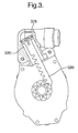
- Japanese Patent Registration No. 3218987 discloses a constitution of a pretensioner for a seat belt retractor, which will be described with reference to FIG. 3 .
- the cylinder since the cylinder has a small thickness at its corners in which a gas pressure is largely applied and abruptly changes its direction, the corners of the cylinders may be damaged on gas discharge.
- Japanese Patent Laid-open Publication No. 1995-251710 discloses a constitution of a pretensioner for a seat belt, which will be described with reference to FIG. 4 .
- the pretensioner for a seat belt of Conventional Art 4 includes an ignition propulsion wadding material operated by a fuse 450 and adapted to a drive device for the seat belt pretensioner, and the drive device includes a piston 430 for performing translation movement of a piston-cylinder unit.
- Great Britain Patent GB1162323 discloses a constitution of a pretensioner for a seat belt, which will be described with reference to FIG. 5 .
- a piston head 528 of a piston 530 of Conventional Art 5 also maintains a state extended from an initial assembly position to a substantially bottom position of the piston accommodating part of the cylinder 520, there is an insufficient space to be pressed by the discharged gas.
- the piston head of the piston is disposed at a lower end of a straight movable guide of the cylinder on initial assembly to form an insufficient space under the piston head, or a step formed at a lower end of the cylinder also narrows the space, it is difficult to sufficiently apply a predetermined gas pressure to a pressure receiving plate.
- An aspect of the present invention is to provide a cylinder in a pretensioner for a seat belt retractor and a pretensioner for a seat belt retractor employing the same capable of applying a sufficient pressure to a pressure receiving plate to increase an upward force and increasing a strength of the cylinder against a high pressure injection gas.
- An embodiment of the invention provides a cylinder in a pretensioner for a seat belt retractor for rewinding a webbing when a vehicle is abruptly decelerated, and when seen from a side view, having an L-shaped hollow part, one part of which forms a gas supply port, and the other part of which forms a straight moving guide hole along which a piston reciprocates, characterized in that the moving guide hole along which the piston reciprocates extends downward beyond a sealing part in an initial assembly state.
- the straight moving guide hole may partially cross the gas supply port.
- a first thick part may be formed inside the L-shaped hollow part to form the straight moving guide hole, and an intermediate passage may be formed between the first thick part and the gas supply part.
- a spherical rotation space may be connected between a lower end of the moving guide hole and the intermediate passage.
- a second thick part may be formed around the spherical rotation space.
- the second thick part may have a thickness gradually thinned from around the spherical rotation space to both sides thereof
- a pretensioner for a seat belt retractor of a vehicle including: a torsion bar on which a webbing is wound; a gear member connected to the torsion bar; a cylinder recited in any one of Claims 1 to 6 and into which a gas is supplied when the vehicle is abruptly decelerated; a piston moved along the moving guide hole formed at a portion of the cylinder, and having a rack formed at a side surface thereof in a longitudinal direction; a cylindrical sealing operation part integrally formed with a bottom of the piston and projecting therefrom; a sealing part coupled to an outer periphery of the sealing operation part to seal between the piston and an inner wall of the cylinder; and a hooking means for hooking the piston at an initial hooking position.
- the sealing part may be an O-ring.
- the sealing part may be a plastic coating part.
- the hooking means may be a position fixing piece connected to the gear member, formed at a base member through which the torsion bar passes, and having a shape meshed with the rack of the piston.
- the base member may have a guide piece disposed at a position opposite to the position fixing piece with the piston interposed therebetween, and having a surface parallel to the piston.
- the cylinder may have a guide cover fixed thereto to guide the piston.
- a cylinder 620 in a pretensioner for a seat belt retractor has an L-shaped hollow shape when seen from a side view. That is, a substantially L-shaped pipe is provided.
- the L-shaped cylinder 620 has one hole acting as a gas supply port 621 connected to an inflator 660, and the other hole acting as a straight moving guide hole 622 through which a piston 630 reciprocates.
- the straight moving guide hole 622 vertically extends downward beyond a position of a sealing part 640 in an initial assembly state.
- the initial assembly state means a state in which the piston 630 is raised by a gas pressure to be appropriately meshed with a gear member 618.
- a rack 633 of the piston 630 is hooked by a hooking means 670 formed at the sealing operation member 680. Therefore, a gap (or a marginal space) is formed between the sealing part 634 and a lower end of the straight moving guide hole 622.
- the sealing part 634 may be formed of an O-ring or a plastic coating part.
- the piston 630 has a length of no more than 6-8cm, in order to extend the straight moving guide hole 622 more than the conventional art, a specific constitution is required in the hollow part.
- the straight moving guide hole 622 is formed to partially and vertically cross the gas supply port 621.
- the L-shaped cylinder 620 has a first thick part 623 disposed at an inner corner to form the straight moving guide hole 622, and an intermediate passage 624 formed between the first thick part 623 and the gas supply port 621.
- a gas passes through the intermediate passage 624 to press a lower end of the piston head 628 formed at a lower end ofthe piston 630.
- a partially spherical rotation space 625 is connected between a lower end of the straight moving guide hole 622 and the gas supply port 621. Therefore, the gas passed through the gas supply port 621 and the intermediate passage 624 can be smoothly introduced into the moving guide hole 622.
- a second thick part 626 may be formed around the partially spherical rotation space 625. Therefore, it is possible to prevent the outer corner part of the cylinder 620 from being broken by a high pressure gas.
- the second thick part 626 may have a thickness gradually thinned from around the spherical rotation space 625 to both sides of the cylinder 620. Therefore, it is possible to reduce a volume of the cylinder 620 while maintaining its strength.
- the pretensioner 610 in accordance with an exemplary embodiment of the present invention includes a torsion bar 614 on which a webbing is wound, a gear member 618 connected to the torsion bar 614, a cylinder 620, a piston 630 moved along the moving guide hole 622 formed at a portion of the cylinder 620, and having a rack 633 formed at a side surface thereof in a longitudinal direction, a cylindrical sealing operation part 632 integrally formed with a bottom of the piston 630 and projecting therefrom; a sealing part 634 coupled to an outer periphery of the sealing operation part 632 to seal between the piston 630 and an inner wall of the cylinder 620; and a hooking means 670 for hooking the piston 630 at an initial hooking position.
- reference numeral 660 designates an inflator 660 installed at a gas supply port 621 of the cylinder 620.
- sealing part 634 is an O-ring, but the sealing part 634 may be a plastic coating part.
- the hooking means 670 is a position fixing piece 672 connected to the gear member 618, formed at a base member 680 through which the torsion bar 614 passes, and having a shape meshed with the rack 633 of the piston 630. That is, the position fixing piece 672 is formed of a plate that is shaped to form the rack 633. Reinforcement plates vertically extend upward and downward from upper and lower ends of the shaped plate.
- the base member 680 has a guide piece 674 opposite to the position fixing piece 672 with the piston 630 interposed therebetween. As shown, a surface of the guide piece 674 opposite to the piston 630 is parallel to the piston 630.
- a guide cover 690 is fixedly installed at the cylinder 610 to guide the piston 630.
- a guide surface parallel to the piston 630 is formed inside the guide cover 690.
- the O-ring 634 seals between the piston 630 and the inner wall of the cylinder 620 to improve sealing performance between the piston 630 and the cylinder 620.
- an insert groove (not shown) may be installed around the sealing operation part 632 to securely install the O-ring 634 therein.
- the straight moving guide hole 622 extends downward beyond the O-ring in an initial assembly state, a space for temporarily storing a gas introduced into the moving guide hole of the piston is expanded to provide marginal time to sufficiently apply an upward force. Therefore, the gas discharged from the gas supply port 621 causes an increase in the upward force by the gas pressure applied to the piston head 628.
- the conventional step in the moving guide hole can be removed to increase a pressure receiving area, thereby maintaining the sufficient upward force against the piston.
- a thick part is formed at an outer corner of a cylinder to maintain durability when a high pressure gas is injected.
Abstract
Description
- The present invention relates to a cylinder in a pretensioner for a seat belt retractor and a pretensioner for a seat belt retractor employing the same, and more particularly, to a cylinder in a pretensioner for a seat belt retractor and a pretensioner for a seat belt retractor employing the same capable of forcedly winding a webbing on a torsion bar upon abrupt deceleration of a vehicle due to collision, and so on, to prevent the webbing from being loosened.
- A conventional seat belt retractor employs a pretensioner for forcedly winding a webbing on a torsion bar upon abrupt deceleration of a vehicle due to collision, and so on, to prevent the webbing from being loosened.
- Several examples of the conventional seat belt retractor will be described below.
- First, Japanese Patent Registration No.
3519302 FIGS. 1A to 1C . - As shown, a
retractor 138 ofConventional Art 1 includes ahousing 112 fixed to a vehicle, and atorsion bar 114 rotatably installed at thehousing 112. Awebbing 116 is wound on thetorsion bar 114. - In addition, the
retractor 138 includes a piston-gear type pretensioner 110 for a seat belt retractor. Agear member 118 is connected to one end of thetorsion bar 114. Therefore, rotation of thegear member 118 causes rotation of thetorsion bar 114 to wind thewebbing 116. - Further, a
cylinder 120 is fixed to thehousing 112. Thecylinder 120 has a hollow cylindrical shape, atip 122 of which is opened adjacent to thegear member 118. - Meanwhile, a
cylindrical recess 126 is formed at abottom surface 124 of thecylinder 120. Therecess 126 has a diameter smaller than an inner diameter of thecylinder 120 such that a position of an O-ring 134 is determined depending on constitution of thebottom surface 124 and therecess 126 of thecylinder 120. In addition, a gas supply port (not shown) is formed at therecess 126 to allow supply of a gas into thecylinder 120 when the vehicle is abruptly decelerated. - Further, a substantially circular
pressure receiving plate 128 is installed in thecylinder 120 to move in thecylinder 120. As a result, when a gas is supplied into thecylinder 120, thepressure receiving plate 128 moves along an arrow (direction C) ofFIG. 1C . - In addition, a
piston 130 is integrally formed with a surface of thepressure receiving plate 128 facing thegear member 118. A rack formed at one side of thepiston 130 corresponds to thegear member 118. When thepiston 130 moves with thepressure receiving plate 128 in the arrow direction C ofFIG. 1C , the rack of thepiston 130 is meshed with thegear member 118 to rotate thegear member 118 in a direction that thewebbing 116 is wound (an arrow A ofFIG. 1C ). - Meanwhile, a cylindrical
seal holding part 132 is integrally formed with thepressure receiving plate 128 facing thebottom surface 124 of thecylinder 120, and the O-ring 134 is disposed on an outer periphery of theseal holding part 132. The O-ring 134 has an elasticity to seal between thepressure receiving plate 128 and aninner wall 136 of thecylinder 120. - In addition, the O-ring interposed between the
pressure receiving plate 128 and thebottom surface 124 of thecylinder 120 prevents thepressure receiving plate 128 from being in direct contact with thebottom surface 124 of thecylinder 120. In this state, the position of thepressure receiving plate 128 is an initial position (an initial assembly position) of thepressure receiving plate 128. Here, theseal holding part 132 is disposed in therecess 126 of thebottom surface 124 of thecylinder 120, with the O-ring 134 being in contact with thebottom surface 124 of thecylinder 120. Further, therecess 126 has a depth such that theseal holding part 132 is not in contact with abottom surface 127 of therecess 126 even when the O-ring is elastically deformed. - Meanwhile, since the piston-gear type pretensioner for a seat belt retractor of
Conventional Art 1 includes a force limiter (not shown), when the force limiter is operated, thegear member 118 is rotated in a counter-winding direction of thewebbing 116 to release thewebbing 116, thereby preventing a passenger from receiving a load more than a predetermined amount. - Eventually, in the case of the pretensioner of
Conventional Art 1, therecess 126 having a diameter smaller than an inner diameter of thecylinder 120 is formed at thebottom surface 124 of thecylinder 120, and a step is formed between theinner wall 136 of thecylinder 120 and an inner wall of therecess 126. In addition, the O-ring 134 is disposed on the step. - Since the step narrows a space between the bottom surface of the
recess 126 and a lower end of theseal holding part 132, a gas pressure provided through the gas supply port may be insufficiently transmitted to the pressure receiving plate. - In addition, according to
Conventional Art 1, a portion of the cylinder adjacent to the gas support port may be weak to be readily broken on gas discharge. - Japanese Patent Registration No.
3819189 FIG. 2 . - As shown, since a
piston head 228 of apiston 230 of Conventional Art 2 maintains a state extended in an initial assembly position to a bottom position in which a straight section of thepiston accommodating part 236 of thecylinder 220 is terminated, there is an insufficient space to be pressed by the discharged gas. - In addition, since the cylinder has a small thickness at its corners in which a gas pressure is largely applied and abruptly changes its direction, the corners of the cylinders may be damaged on gas discharge.
- Japanese Patent Registration No.
3218987 FIG. 3 . - As shown, since a
piston head 328 of apiston 330 of Conventional Art 3 also maintains a state extended from an initial assembly position to a bottom position in which a straight section of the piston accommodating part of thecylinder 320 is terminated, there is an insufficient space to be pressed by the discharged gas. - In addition, since the cylinder has a small thickness at its corners in which a gas pressure is largely applied and abruptly changes its direction, the corners of the cylinders may be damaged on gas discharge.
- Japanese Patent Laid-open Publication No.
1995-251710 FIG. 4 . - As shown, the pretensioner for a seat belt of Conventional Art 4 includes an ignition propulsion wadding material operated by a
fuse 450 and adapted to a drive device for the seat belt pretensioner, and the drive device includes apiston 430 for performing translation movement of a piston-cylinder unit. - However, in the seat belt pretensioner of Conventional Art 4, since an end of the
piston 430 is disposed on a step of an inner wall of acylinder 420 to maintain an initial assembly state, an area on which a gas pressure is applied is reduced to decrease operation efficiency of the gas pressure against a lower end of thepiston 430. - Great Britain Patent
GB1162323 FIG. 5 . - As shown, since a
piston head 528 of apiston 530 of Conventional Art 5 also maintains a state extended from an initial assembly position to a substantially bottom position of the piston accommodating part of thecylinder 520, there is an insufficient space to be pressed by the discharged gas. - As described above, since the piston head of the piston is disposed at a lower end of a straight movable guide of the cylinder on initial assembly to form an insufficient space under the piston head, or a step formed at a lower end of the cylinder also narrows the space, it is difficult to sufficiently apply a predetermined gas pressure to a pressure receiving plate.
- An aspect of the present invention is to provide a cylinder in a pretensioner for a seat belt retractor and a pretensioner for a seat belt retractor employing the same capable of applying a sufficient pressure to a pressure receiving plate to increase an upward force and increasing a strength of the cylinder against a high pressure injection gas.
- An embodiment of the invention provides a cylinder in a pretensioner for a seat belt retractor for rewinding a webbing when a vehicle is abruptly decelerated, and when seen from a side view, having an L-shaped hollow part, one part of which forms a gas supply port, and the other part of which forms a straight moving guide hole along which a piston reciprocates, characterized in that the moving guide hole along which the piston reciprocates extends downward beyond a sealing part in an initial assembly state.
- At this time, the straight moving guide hole may partially cross the gas supply port.
- For this purpose, a first thick part may be formed inside the L-shaped hollow part to form the straight moving guide hole, and an intermediate passage may be formed between the first thick part and the gas supply part.
- In addition, a spherical rotation space may be connected between a lower end of the moving guide hole and the intermediate passage.
- Further, a second thick part may be formed around the spherical rotation space.
- Furthermore, the second thick part may have a thickness gradually thinned from around the spherical rotation space to both sides thereof
- Another embodiment of the invention provides a pretensioner for a seat belt retractor of a vehicle including: a torsion bar on which a webbing is wound; a gear member connected to the torsion bar; a cylinder recited in any one of
Claims 1 to 6 and into which a gas is supplied when the vehicle is abruptly decelerated; a piston moved along the moving guide hole formed at a portion of the cylinder, and having a rack formed at a side surface thereof in a longitudinal direction; a cylindrical sealing operation part integrally formed with a bottom of the piston and projecting therefrom; a sealing part coupled to an outer periphery of the sealing operation part to seal between the piston and an inner wall of the cylinder; and a hooking means for hooking the piston at an initial hooking position. - In this embodiment, the sealing part may be an O-ring.
- In addition, the sealing part may be a plastic coating part.
- Further, the hooking means may be a position fixing piece connected to the gear member, formed at a base member through which the torsion bar passes, and having a shape meshed with the rack of the piston.
- Furthermore, the base member may have a guide piece disposed at a position opposite to the position fixing piece with the piston interposed therebetween, and having a surface parallel to the piston.
- In addition, the cylinder may have a guide cover fixed thereto to guide the piston.
- The above and other objects, features and advantages of the present invention will be more apparent from the following detailed description taken in conjunction with the accompanying drawings, in which:
-
FIGS. 1A to 1C are views showing a constitution of a pretensioner for a seat belt retractor ofConventional Art 1; -
FIG. 2 is a cross-sectional view showing a constitution of a pretensioner for a seat belt retractor of Conventional Art 2; -
FIG. 3 is a cross-sectional view showing a constitution of a pretensioner for a seat belt retractor of Conventional Art 3; -
FIG. 4 is a cross-sectional view showing a constitution of a pretensioner for a seat belt retractor of Conventional Art 4; -
FIG. 5 is a cross-sectional view showing a constitution of a pretensioner for a seat belt retractor of Conventional Art 5; -
FIG. 6A is a partially cut perspective view of a cylinder in a pretensioner for a seat belt retractor in accordance with an exemplary embodiment of the present invention; -
FIG. 6B is a longitudinal cross-sectioned view ofthe cylinder in a pretensioner for a seat belt retractor in accordance with an exemplary embodiment of the present invention; -
FIG. 6C is a perspective view of a pretensioner for a seat belt retractor, in which a cylinder in accordance with an exemplary embodiment of the present invention is installed; -
FIG. 6D is a side view of the pretensioner for a seat belt retractor, from which the cylinder ofFIG. 6C is removed; -
FIG. 6E is an exploded perspective view ofthe pretensioner ofFIG. 6C ; and -
FIG. 6F is a cross-ssectioned view showing the cylinder and the piston in accordance with an exemplary embodiment of the present invention, which are assembled to each other. - Hereinafter, exemplary embodiments of the present invention will be described with reference to the accompanying drawings.
- As shown, a
cylinder 620 in a pretensioner for a seat belt retractor has an L-shaped hollow shape when seen from a side view. That is, a substantially L-shaped pipe is provided. - The L-shaped
cylinder 620 has one hole acting as agas supply port 621 connected to aninflator 660, and the other hole acting as a straight movingguide hole 622 through which apiston 630 reciprocates. - In accordance with the present invention, the straight moving
guide hole 622 vertically extends downward beyond a position of a sealing part 640 in an initial assembly state. The initial assembly state means a state in which thepiston 630 is raised by a gas pressure to be appropriately meshed with agear member 618. In the initial assembly state, arack 633 of thepiston 630 is hooked by a hooking means 670 formed at the sealingoperation member 680. Therefore, a gap (or a marginal space) is formed between the sealingpart 634 and a lower end of the straight movingguide hole 622. - The sealing
part 634 may be formed of an O-ring or a plastic coating part. In addition, since thepiston 630 has a length of no more than 6-8cm, in order to extend the straight movingguide hole 622 more than the conventional art, a specific constitution is required in the hollow part. For example, as shown, the straight movingguide hole 622 is formed to partially and vertically cross thegas supply port 621. - Further, the L-shaped
cylinder 620 has a firstthick part 623 disposed at an inner corner to form the straight movingguide hole 622, and anintermediate passage 624 formed between the firstthick part 623 and thegas supply port 621. A gas passes through theintermediate passage 624 to press a lower end of thepiston head 628 formed at a lower end ofthepiston 630. - Eventually, since the first
thick part 623 causes the straight movingguide hole 622 to be deeper, a space between the lower end of thepiston head 628 and an intermediate inner wall of thecylinder 620 becomes wider. - Moreover, a partially
spherical rotation space 625 is connected between a lower end of the straight movingguide hole 622 and thegas supply port 621. Therefore, the gas passed through thegas supply port 621 and theintermediate passage 624 can be smoothly introduced into the movingguide hole 622. - A second
thick part 626 may be formed around the partiallyspherical rotation space 625. Therefore, it is possible to prevent the outer corner part of thecylinder 620 from being broken by a high pressure gas. - The second
thick part 626 may have a thickness gradually thinned from around thespherical rotation space 625 to both sides of thecylinder 620. Therefore, it is possible to reduce a volume of thecylinder 620 while maintaining its strength. - In the drawings, a structure of a
pretensioner 610 including acylinder 620 in accordance with an exemplary embodiment of the present invention is partially illustrated. - As shown, the
pretensioner 610 in accordance with an exemplary embodiment of the present invention includes atorsion bar 614 on which a webbing is wound, agear member 618 connected to thetorsion bar 614, acylinder 620, apiston 630 moved along the movingguide hole 622 formed at a portion of thecylinder 620, and having arack 633 formed at a side surface thereof in a longitudinal direction, a cylindricalsealing operation part 632 integrally formed with a bottom of thepiston 630 and projecting therefrom; a sealingpart 634 coupled to an outer periphery of the sealingoperation part 632 to seal between thepiston 630 and an inner wall of thecylinder 620; and a hooking means 670 for hooking thepiston 630 at an initial hooking position. In the drawings,reference numeral 660 designates an inflator 660 installed at agas supply port 621 of thecylinder 620. - In the drawings, the sealing
part 634 is an O-ring, but the sealingpart 634 may be a plastic coating part. - The hooking means 670 is a
position fixing piece 672 connected to thegear member 618, formed at abase member 680 through which thetorsion bar 614 passes, and having a shape meshed with therack 633 of thepiston 630.
That is, theposition fixing piece 672 is formed of a plate that is shaped to form therack 633. Reinforcement plates vertically extend upward and downward from upper and lower ends of the shaped plate. - Meanwhile, the
base member 680 has aguide piece 674 opposite to theposition fixing piece 672 with thepiston 630 interposed therebetween. As shown, a surface of theguide piece 674 opposite to thepiston 630 is parallel to thepiston 630. - Moreover, a
guide cover 690 is fixedly installed at thecylinder 610 to guide thepiston 630. A guide surface parallel to thepiston 630 is formed inside theguide cover 690. - As a result, when the vehicle is abruptly decelerated, e.g. due to collision, a gas is supplied into the
cylinder 620 to move thepiston 630 upward. Therefore, movement of therack 633 formed at one side of thepiston 630 causes rotation of thegear member 618 meshed with therack 633 in a winding direction of the webbing. - When the
gear member 618 is rotated in the winding direction of the webbing, the webbing is rewound on thetorsion bar 614 to closely adhere a passenger to a seat. - Here, since a gas pressure is applied to an O-
ring 634 when thepiston 630 is moved by the gas pressure, the O-ring 634 is pushed by thepiston 630 to be held at the sealingoperation part 632. Therefore, the O-ring 634 seals between thepiston 630 and the inner wall of thecylinder 620 to improve sealing performance between thepiston 630 and thecylinder 620. - In addition, an insert groove (not shown) may be installed around the sealing
operation part 632 to securely install the O-ring 634 therein. - Further, since the straight moving
guide hole 622 extends downward beyond the O-ring in an initial assembly state, a space for temporarily storing a gas introduced into the moving guide hole of the piston is expanded to provide marginal time to sufficiently apply an upward force. Therefore, the gas discharged from thegas supply port 621 causes an increase in the upward force by the gas pressure applied to thepiston head 628. - As can be seen from the foregoing, since a straight moving guide hole in a cylinder, through which a piston reciprocates, extends downward beyond an O-ring in an initial assembly state, it is possible to maintain a wide space in the moving guide hole under a piston head.
- Therefore, it is possible to secure marginal time for providing a sufficient upward force due to a temporary storage space for a gas introduced into the moving guide hole of the piston.
- In addition, the conventional step in the moving guide hole can be removed to increase a pressure receiving area, thereby maintaining the sufficient upward force against the piston.
- Further, a thick part is formed at an outer corner of a cylinder to maintain durability when a high pressure gas is injected.
- While this invention has been described with reference to exemplary embodiments thereof, it will be clear to those of ordinary skill in the art to which the invention pertains that various modifications may be made to the described embodiments without departing from the spirit and scope of the invention as defined in the appended claims and their equivalents.
Claims (12)
- A cylinder in a pretensioner for a seat belt retractor, when seen from a side view, having an L-shaped hollow part, one part of which forms a gas supply port and the other part of which forms a straight moving guide hole along which a piston reciprocates,
characterized in that the moving guide hole along which the piston reciprocates extends downward beyond a sealing part in an initial assembly state. - The cylinder in a pretensioner for a seat belt retractor according to Claim 1, wherein the straight moving guide hole partially crosses the gas supply port.
- The cylinder in a pretensioner for a seat belt retractor according to Claim 2, wherein a first thick part is formed inside the L-shaped hollow part to form the straight moving guide hole, and an intermediate passage is formed between the first thick part and the gas supply part.
- The cylinder in a pretensioner for a seat belt retractor according to Claim 3, wherein a spherical rotation space is connected between a lower end of the moving guide hole and the intermediate passage.
- The cylinder in a pretensioner for a seat belt retractor according to Claim 4, wherein a second thick part is formed around the spherical rotation space.
- The cylinder in a pretensioner for a seat belt retractor according to Claim 5, wherein the second thick part has a thickness gradually thinned from around the spherical rotation space to both sides thereof
- A pretensioner for a seat belt retractor of a vehicle, comprising;
a torsion bar on which a webbing is wound;
a gear member connected to the torsion bar;
a cylinder recited in any one of Claims 1 to 6 and into which a gas is supplied when the vehicle is abruptly decelerated;
a piston moved along the moving guide hole formed at a portion of the cylinder, and having a rack formed at a side surface thereof in a longitudinal direction;
a cylindrical sealing operation part integrally formed with a bottom of the piston and projecting therefrom;
a sealing part coupled to an outer periphery of the sealing operation part to seal between the piston and an inner wall of the cylinder; and
a hooking means for hooking the piston at an initial hooking position. - The pretensioner for a seat belt retractor of a vehicle according to Claim 7, wherein the sealing part is an O-ring.
- The pretensioner for a seat belt retractor of a vehicle according to Claim 7, wherein the sealing part is a plastic coating part.
- The pretensioner for a seat belt retractor of a vehicle according to Claim 7, wherein the hooking means is a position fixing piece connected to the gear member, formed at a base member through which the torsion bar passes, and having a shape meshed with the rack of the piston.
- The pretensioner for a seat belt retractor of a vehicle according to Claim 10, wherein the base member has a guide piece disposed at a position opposite to the position fixing piece with the piston interposed therebetween, and has a surface parallel to the piston.
- The pretensioner for a seat belt retractor of a vehicle according to Claim 11, wherein the cylinder has a guide cover fixed thereto to guide the piston.
Applications Claiming Priority (1)
| Application Number | Priority Date | Filing Date | Title |
|---|---|---|---|
| KR1020070047791A KR100835932B1 (en) | 2007-05-16 | 2007-05-16 | Pre-tensioner for vehicle retractor |
Publications (3)
| Publication Number | Publication Date |
|---|---|
| EP1992532A2 true EP1992532A2 (en) | 2008-11-19 |
| EP1992532A3 EP1992532A3 (en) | 2011-10-19 |
| EP1992532B1 EP1992532B1 (en) | 2014-01-08 |
Family
ID=39535317
Family Applications (2)
| Application Number | Title | Priority Date | Filing Date |
|---|---|---|---|
| EP08154549.3A Expired - Fee Related EP1992532B1 (en) | 2007-05-16 | 2008-04-15 | Cylinder in pretensioner for seat belt retractor and pretensioner for seat belt retractor employing the same |
| EP08156314.0A Expired - Fee Related EP1992533B1 (en) | 2007-05-16 | 2008-05-15 | Cylinder in a pretensioner for seat belt retractor and pretensioner for seat belt retractor employing the same |
Family Applications After (1)
| Application Number | Title | Priority Date | Filing Date |
|---|---|---|---|
| EP08156314.0A Expired - Fee Related EP1992533B1 (en) | 2007-05-16 | 2008-05-15 | Cylinder in a pretensioner for seat belt retractor and pretensioner for seat belt retractor employing the same |
Country Status (6)
| Country | Link |
|---|---|
| US (1) | US8042758B2 (en) |
| EP (2) | EP1992532B1 (en) |
| JP (1) | JP4189016B2 (en) |
| KR (1) | KR100835932B1 (en) |
| CN (1) | CN101306675B (en) |
| BR (1) | BRPI0703051A2 (en) |
Cited By (1)
| Publication number | Priority date | Publication date | Assignee | Title |
|---|---|---|---|---|
| EP2716506A1 (en) * | 2011-05-31 | 2014-04-09 | Ashimori Industry Co., Ltd. | Seatbelt retractor |
Families Citing this family (14)
| Publication number | Priority date | Publication date | Assignee | Title |
|---|---|---|---|---|
| DE102004032063B4 (en) * | 2004-07-01 | 2006-10-12 | Autoliv Development Ab | Seat belt tensioning device with bent tube |
| KR100902243B1 (en) | 2007-12-18 | 2009-06-11 | 델파이코리아 주식회사 | Pre-tension of retractor |
| JP5314531B2 (en) * | 2008-09-04 | 2013-10-16 | 株式会社東海理化電機製作所 | Pretensioner |
| JP5198983B2 (en) * | 2008-09-04 | 2013-05-15 | 株式会社東海理化電機製作所 | Pretensioner and pretensioner manufacturing method |
| JP5433255B2 (en) * | 2009-03-04 | 2014-03-05 | 芦森工業株式会社 | Seat belt retractor |
| JP5518654B2 (en) | 2010-09-17 | 2014-06-11 | 株式会社東海理化電機製作所 | Webbing take-up device |
| CN102060217B (en) * | 2010-10-29 | 2014-06-18 | 宁波大叶园林工业有限公司 | Ball-containing position lock and pipe coiling device with multiple damping mechanisms |
| US9248803B2 (en) * | 2010-12-02 | 2016-02-02 | Autoliv Development Ab | Belt retractor with a switchable force-limiting device for a seatbelt of a motor vehicle |
| DE102011014127A1 (en) * | 2011-03-15 | 2012-09-20 | Trw Automotive Gmbh | linear actuator |
| JP5734889B2 (en) | 2012-02-10 | 2015-06-17 | 株式会社東海理化電機製作所 | Pretensioner mechanism |
| JP2014108764A (en) * | 2012-12-04 | 2014-06-12 | Ashimori Ind Co Ltd | Retractor for seat belt |
| US8960724B2 (en) | 2013-03-15 | 2015-02-24 | Autoliv Asp, Inc. | Controlled pressure release for seatbelt pretensioning devices |
| US9821758B2 (en) * | 2016-02-05 | 2017-11-21 | Ford Global Technologies, Llc | Pretensioning, force-limiting seat belt assembly |
| CN112092768A (en) * | 2020-09-10 | 2020-12-18 | 西安宝鑫自动化设备有限公司 | Novel hydraulic control safety belt structure |
Citations (5)
| Publication number | Priority date | Publication date | Assignee | Title |
|---|---|---|---|---|
| GB1162323A (en) | 1967-04-26 | 1969-08-27 | James Martin | Improvements in or relating to Inertia Reel Devices for Safety Harnesses |
| JPH07251710A (en) | 1994-02-11 | 1995-10-03 | Trw Repa Gmbh | Pre-tensioner of belt for safety belt |
| JP3218987B2 (en) | 1996-08-29 | 2001-10-15 | 日本精工株式会社 | Pretensioner for seat belt retractor |
| JP3519302B2 (en) | 1999-02-09 | 2004-04-12 | 株式会社東海理化電機製作所 | Pretensioner for webbing take-up device |
| JP3819189B2 (en) | 1999-10-06 | 2006-09-06 | 株式会社東海理化電機製作所 | Pretensioner |
Family Cites Families (36)
| Publication number | Priority date | Publication date | Assignee | Title |
|---|---|---|---|---|
| JPS54138232A (en) * | 1978-04-18 | 1979-10-26 | Takada Kogyo Kk | Emergency lock system belt takinggup motion |
| US4278216A (en) * | 1979-04-19 | 1981-07-14 | Juichiro Takada | Double-safety emergency locking belt retractor |
| SE449722B (en) * | 1980-06-02 | 1987-05-18 | Takata Kojyo Co | EMERGENCY WELDING ROLLER FOR VEHICLE SEAT BELTS |
| JPS5740456U (en) * | 1980-08-19 | 1982-03-04 | ||
| US4726540A (en) * | 1986-11-17 | 1988-02-23 | General Motors Corporation | Variable sensitivity seat belt retractor |
| JP3093852B2 (en) * | 1992-01-30 | 2000-10-03 | タカタ株式会社 | Seat belt retractor |
| GB9215855D0 (en) * | 1992-07-25 | 1992-09-09 | Bsrd Ltd | Improvements to emergency locking passenger safety belt mechanisms |
| JP3322773B2 (en) * | 1994-07-06 | 2002-09-09 | エヌエスケー・オートリブ株式会社 | Seat belt retractor with pretensioner |
| WO1996003295A1 (en) * | 1994-07-21 | 1996-02-08 | Alliedsignal Inc. | Seat belt retractor and improved sensing mechanism |
| US5495994A (en) * | 1994-09-07 | 1996-03-05 | Trw Vehicle Safety Systems Inc. | Inertia sensitive seat belt retractor |
| JP3787001B2 (en) * | 1996-05-24 | 2006-06-21 | エヌエスケー・オートリブ株式会社 | Seat belt retractor |
| US5906327A (en) * | 1998-02-17 | 1999-05-25 | Breed Automotive Technology, Inc. | Pretensioner or belt tightener |
| EP0940603B1 (en) * | 1998-03-04 | 2004-06-09 | Kabushiki Kaisha Tokai-Rika-Denki-Seisakusho | Webbing retractor |
| JP4109780B2 (en) * | 1998-03-06 | 2008-07-02 | 株式会社東海理化電機製作所 | Gear mechanism and webbing take-up device |
| US5984223A (en) * | 1998-06-05 | 1999-11-16 | Takata Corporation | Seat belt retractor and its spool |
| DE19837927C2 (en) * | 1998-08-20 | 2001-07-12 | Breed Automotive Tech | Device for tightening a motor vehicle seat belt |
| US6275807B1 (en) * | 1998-08-26 | 2001-08-14 | Metropolitan Life Insurance Company | Computer system and methods for management, and control of annuities and distribution of annuity payments |
| US7376608B1 (en) * | 1998-09-25 | 2008-05-20 | Lincoln National Life Insurance Company | Method and system for providing retirement income benefits |
| JP2000108847A (en) | 1998-10-05 | 2000-04-18 | Tokai Rika Co Ltd | Webbing winder |
| JP3980777B2 (en) * | 1998-11-02 | 2007-09-26 | 株式会社東海理化電機製作所 | Webbing take-up device |
| AU754709B2 (en) * | 1999-02-16 | 2002-11-21 | Kabushiki Kaisha Tokai-Rika-Denki-Seisakusho | Webbing take-up device |
| JP3437488B2 (en) | 1999-02-16 | 2003-08-18 | 株式会社東海理化電機製作所 | Webbing take-up device |
| JP3490630B2 (en) | 1999-04-16 | 2004-01-26 | 株式会社東海理化電機製作所 | Pretensioner |
| GB2349119B (en) * | 1999-04-21 | 2001-05-30 | Breed Automotive Tech | A sensor for a seat belt retractor |
| KR100435373B1 (en) * | 2001-08-28 | 2004-06-10 | 현대자동차주식회사 | Structure of pretensioner for automobile |
| JP3984061B2 (en) | 2002-01-25 | 2007-09-26 | 芦森工業株式会社 | Seat belt retractor |
| JP3934483B2 (en) * | 2002-05-21 | 2007-06-20 | 芦森工業株式会社 | Seat belt retractor |
| US6698677B1 (en) * | 2002-11-12 | 2004-03-02 | H. Koch & Sons Co., Inc. | Restraint pretensioner |
| JP4295552B2 (en) * | 2003-05-16 | 2009-07-15 | 株式会社東海理化電機製作所 | Webbing take-up device |
| JP3798394B2 (en) | 2003-09-18 | 2006-07-19 | 株式会社東海理化電機製作所 | Pretensioner |
| JP2005271623A (en) * | 2004-03-23 | 2005-10-06 | Tokai Rika Co Ltd | Webbing winding device |
| ZA200502648B (en) * | 2004-04-01 | 2005-12-28 | Discovery Life Ltd | A method of managing a life insurance policy and system therefor |
| WO2006044953A1 (en) * | 2004-10-19 | 2006-04-27 | Autoliv Asp, Inc. | Adaptive restraint system with retractor having pretensioner |
| JP4476126B2 (en) | 2005-01-06 | 2010-06-09 | 株式会社東海理化電機製作所 | Webbing take-up device |
| US7401815B2 (en) * | 2005-03-17 | 2008-07-22 | Antoliv Asp, Inc. | Dual spool retractor seat belt system |
| US7631830B2 (en) * | 2006-04-17 | 2009-12-15 | Key Safety Systems, Inc. | Retractor with rotary rack pretensioner |
-
2007
- 2007-05-16 KR KR1020070047791A patent/KR100835932B1/en active IP Right Grant
- 2007-07-20 BR BRPI0703051-7A patent/BRPI0703051A2/en not_active IP Right Cessation
- 2007-07-20 JP JP2007189135A patent/JP4189016B2/en not_active Expired - Fee Related
- 2007-07-20 CN CN2007101361914A patent/CN101306675B/en not_active Expired - Fee Related
-
2008
- 2008-04-15 EP EP08154549.3A patent/EP1992532B1/en not_active Expired - Fee Related
- 2008-05-14 US US12/152,630 patent/US8042758B2/en not_active Expired - Fee Related
- 2008-05-15 EP EP08156314.0A patent/EP1992533B1/en not_active Expired - Fee Related
Patent Citations (5)
| Publication number | Priority date | Publication date | Assignee | Title |
|---|---|---|---|---|
| GB1162323A (en) | 1967-04-26 | 1969-08-27 | James Martin | Improvements in or relating to Inertia Reel Devices for Safety Harnesses |
| JPH07251710A (en) | 1994-02-11 | 1995-10-03 | Trw Repa Gmbh | Pre-tensioner of belt for safety belt |
| JP3218987B2 (en) | 1996-08-29 | 2001-10-15 | 日本精工株式会社 | Pretensioner for seat belt retractor |
| JP3519302B2 (en) | 1999-02-09 | 2004-04-12 | 株式会社東海理化電機製作所 | Pretensioner for webbing take-up device |
| JP3819189B2 (en) | 1999-10-06 | 2006-09-06 | 株式会社東海理化電機製作所 | Pretensioner |
Cited By (2)
| Publication number | Priority date | Publication date | Assignee | Title |
|---|---|---|---|---|
| EP2716506A1 (en) * | 2011-05-31 | 2014-04-09 | Ashimori Industry Co., Ltd. | Seatbelt retractor |
| EP2716506A4 (en) * | 2011-05-31 | 2014-11-12 | Ashimori Ind Co Ltd | Seatbelt retractor |
Also Published As
| Publication number | Publication date |
|---|---|
| CN101306675A (en) | 2008-11-19 |
| EP1992532A3 (en) | 2011-10-19 |
| EP1992533A3 (en) | 2011-01-26 |
| KR100835932B1 (en) | 2008-06-09 |
| JP4189016B2 (en) | 2008-12-03 |
| BRPI0703051A2 (en) | 2009-01-06 |
| US20090134691A1 (en) | 2009-05-28 |
| JP2008285136A (en) | 2008-11-27 |
| CN101306675B (en) | 2013-01-02 |
| US8042758B2 (en) | 2011-10-25 |
| EP1992533A2 (en) | 2008-11-19 |
| EP1992532B1 (en) | 2014-01-08 |
| EP1992533B1 (en) | 2014-06-04 |
Similar Documents
| Publication | Publication Date | Title |
|---|---|---|
| EP1992532A2 (en) | Cylinder in pretensioner for seat belt retractor and pretensioner for seat belt retractor employing the same | |
| US5924722A (en) | Air bag apparatus | |
| EP1992528A2 (en) | Seat belt retractor | |
| US6575498B2 (en) | Webbing retractor | |
| US20060144983A1 (en) | Webbing retractor | |
| KR20000057103A (en) | Webbing retractor | |
| EP1028040B1 (en) | Pretensioner for webbing retractor | |
| JP2007045180A (en) | Pretensioner and seat belt device | |
| WO2012165410A1 (en) | Seatbelt retractor | |
| US8573526B2 (en) | Webbing take-up device | |
| US6626388B2 (en) | Webbing retractor | |
| US8376406B2 (en) | Pretensioner mechanism | |
| CN114364580A (en) | Webbing retractor | |
| US9310005B2 (en) | Clamping device, in particular for hoses | |
| US20120001009A1 (en) | Safey belt device | |
| US20210129790A1 (en) | Seat belt retractor | |
| KR100902243B1 (en) | Pre-tension of retractor | |
| US11904798B2 (en) | Webbing take-up device | |
| EP3098118B1 (en) | Webbing take-up device | |
| JP2014151730A (en) | Webbing winder | |
| JP5032394B2 (en) | Webbing take-up device | |
| JP2000198413A (en) | Seat belt device | |
| CN220430087U (en) | Airbag mounting assembly for vehicle, vehicle seat and vehicle | |
| JP2009269463A (en) | Webbing winding device |
Legal Events
| Date | Code | Title | Description |
|---|---|---|---|
| PUAI | Public reference made under article 153(3) epc to a published international application that has entered the european phase |
Free format text: ORIGINAL CODE: 0009012 |
|
| AK | Designated contracting states |
Kind code of ref document: A2 Designated state(s): AT BE BG CH CY CZ DE DK EE ES FI FR GB GR HR HU IE IS IT LI LT LU LV MC MT NL NO PL PT RO SE SI SK TR |
|
| AX | Request for extension of the european patent |
Extension state: AL BA MK RS |
|
| RAP1 | Party data changed (applicant data changed or rights of an application transferred) |
Owner name: AUTOLIV DEVELOPMENT AB |
|
| PUAL | Search report despatched |
Free format text: ORIGINAL CODE: 0009013 |
|
| AK | Designated contracting states |
Kind code of ref document: A3 Designated state(s): AT BE BG CH CY CZ DE DK EE ES FI FR GB GR HR HU IE IS IT LI LT LU LV MC MT NL NO PL PT RO SE SI SK TR |
|
| AX | Request for extension of the european patent |
Extension state: AL BA MK RS |
|
| RIC1 | Information provided on ipc code assigned before grant |
Ipc: B60R 22/46 20060101AFI20110913BHEP |
|
| 17P | Request for examination filed |
Effective date: 20120417 |
|
| AKX | Designation fees paid |
Designated state(s): DE FR IT |
|
| GRAP | Despatch of communication of intention to grant a patent |
Free format text: ORIGINAL CODE: EPIDOSNIGR1 |
|
| GRAS | Grant fee paid |
Free format text: ORIGINAL CODE: EPIDOSNIGR3 |
|
| GRAA | (expected) grant |
Free format text: ORIGINAL CODE: 0009210 |
|
| AK | Designated contracting states |
Kind code of ref document: B1 Designated state(s): DE FR IT |
|
| REG | Reference to a national code |
Ref country code: DE Ref legal event code: R096 Ref document number: 602008029718 Country of ref document: DE Effective date: 20140220 |
|
| REG | Reference to a national code |
Ref country code: DE Ref legal event code: R097 Ref document number: 602008029718 Country of ref document: DE |
|
| PLBE | No opposition filed within time limit |
Free format text: ORIGINAL CODE: 0009261 |
|
| STAA | Information on the status of an ep patent application or granted ep patent |
Free format text: STATUS: NO OPPOSITION FILED WITHIN TIME LIMIT |
|
| 26N | No opposition filed |
Effective date: 20141009 |
|
| REG | Reference to a national code |
Ref country code: DE Ref legal event code: R097 Ref document number: 602008029718 Country of ref document: DE Effective date: 20141009 |
|
| REG | Reference to a national code |
Ref country code: FR Ref legal event code: PLFP Year of fee payment: 9 |
|
| REG | Reference to a national code |
Ref country code: FR Ref legal event code: PLFP Year of fee payment: 10 |
|
| REG | Reference to a national code |
Ref country code: FR Ref legal event code: PLFP Year of fee payment: 11 |
|
| PGFP | Annual fee paid to national office [announced via postgrant information from national office to epo] |
Ref country code: IT Payment date: 20190426 Year of fee payment: 12 Ref country code: DE Payment date: 20190503 Year of fee payment: 12 |
|
| PGFP | Annual fee paid to national office [announced via postgrant information from national office to epo] |
Ref country code: FR Payment date: 20190430 Year of fee payment: 12 |
|
| REG | Reference to a national code |
Ref country code: DE Ref legal event code: R119 Ref document number: 602008029718 Country of ref document: DE |
|
| PG25 | Lapsed in a contracting state [announced via postgrant information from national office to epo] |
Ref country code: FR Free format text: LAPSE BECAUSE OF NON-PAYMENT OF DUE FEES Effective date: 20200430 Ref country code: DE Free format text: LAPSE BECAUSE OF NON-PAYMENT OF DUE FEES Effective date: 20201103 |
|
| PG25 | Lapsed in a contracting state [announced via postgrant information from national office to epo] |
Ref country code: IT Free format text: LAPSE BECAUSE OF NON-PAYMENT OF DUE FEES Effective date: 20200415 |