EP1992504A1 - Motorcycle tire for off-road traveling - Google Patents
Motorcycle tire for off-road traveling Download PDFInfo
- Publication number
- EP1992504A1 EP1992504A1 EP08008456A EP08008456A EP1992504A1 EP 1992504 A1 EP1992504 A1 EP 1992504A1 EP 08008456 A EP08008456 A EP 08008456A EP 08008456 A EP08008456 A EP 08008456A EP 1992504 A1 EP1992504 A1 EP 1992504A1
- Authority
- EP
- European Patent Office
- Prior art keywords
- blocks
- top surface
- block
- tire
- profile
- Prior art date
- Legal status (The legal status is an assumption and is not a legal conclusion. Google has not performed a legal analysis and makes no representation as to the accuracy of the status listed.)
- Granted
Links
Images


Classifications
-
- B—PERFORMING OPERATIONS; TRANSPORTING
- B60—VEHICLES IN GENERAL
- B60C—VEHICLE TYRES; TYRE INFLATION; TYRE CHANGING; CONNECTING VALVES TO INFLATABLE ELASTIC BODIES IN GENERAL; DEVICES OR ARRANGEMENTS RELATED TO TYRES
- B60C11/00—Tyre tread bands; Tread patterns; Anti-skid inserts
- B60C11/03—Tread patterns
- B60C11/11—Tread patterns in which the raised area of the pattern consists only of isolated elements, e.g. blocks
-
- B—PERFORMING OPERATIONS; TRANSPORTING
- B60—VEHICLES IN GENERAL
- B60C—VEHICLE TYRES; TYRE INFLATION; TYRE CHANGING; CONNECTING VALVES TO INFLATABLE ELASTIC BODIES IN GENERAL; DEVICES OR ARRANGEMENTS RELATED TO TYRES
- B60C11/00—Tyre tread bands; Tread patterns; Anti-skid inserts
- B60C11/0083—Tyre tread bands; Tread patterns; Anti-skid inserts characterised by the curvature of the tyre tread
-
- B—PERFORMING OPERATIONS; TRANSPORTING
- B60—VEHICLES IN GENERAL
- B60C—VEHICLE TYRES; TYRE INFLATION; TYRE CHANGING; CONNECTING VALVES TO INFLATABLE ELASTIC BODIES IN GENERAL; DEVICES OR ARRANGEMENTS RELATED TO TYRES
- B60C11/00—Tyre tread bands; Tread patterns; Anti-skid inserts
- B60C11/03—Tread patterns
- B60C11/13—Tread patterns characterised by the groove cross-section, e.g. for buttressing or preventing stone-trapping
- B60C11/1376—Three dimensional block surfaces departing from the enveloping tread contour
-
- B—PERFORMING OPERATIONS; TRANSPORTING
- B60—VEHICLES IN GENERAL
- B60C—VEHICLE TYRES; TYRE INFLATION; TYRE CHANGING; CONNECTING VALVES TO INFLATABLE ELASTIC BODIES IN GENERAL; DEVICES OR ARRANGEMENTS RELATED TO TYRES
- B60C2200/00—Tyres specially adapted for particular applications
- B60C2200/10—Tyres specially adapted for particular applications for motorcycles, scooters or the like
-
- B—PERFORMING OPERATIONS; TRANSPORTING
- B60—VEHICLES IN GENERAL
- B60C—VEHICLE TYRES; TYRE INFLATION; TYRE CHANGING; CONNECTING VALVES TO INFLATABLE ELASTIC BODIES IN GENERAL; DEVICES OR ARRANGEMENTS RELATED TO TYRES
- B60C2200/00—Tyres specially adapted for particular applications
- B60C2200/14—Tyres specially adapted for particular applications for off-road use
-
- Y—GENERAL TAGGING OF NEW TECHNOLOGICAL DEVELOPMENTS; GENERAL TAGGING OF CROSS-SECTIONAL TECHNOLOGIES SPANNING OVER SEVERAL SECTIONS OF THE IPC; TECHNICAL SUBJECTS COVERED BY FORMER USPC CROSS-REFERENCE ART COLLECTIONS [XRACs] AND DIGESTS
- Y10—TECHNICAL SUBJECTS COVERED BY FORMER USPC
- Y10S—TECHNICAL SUBJECTS COVERED BY FORMER USPC CROSS-REFERENCE ART COLLECTIONS [XRACs] AND DIGESTS
- Y10S152/00—Resilient tires and wheels
- Y10S152/902—Non-directional tread pattern having no circumferential rib and having blocks defined by circumferential grooves and transverse grooves
Definitions
- the present invention relates to a motorcycle tire suitable for off-road traveling, and more particularly to an off-road motorcycle tire having a steering stability improved by devising the circumferential profile shape of the surface of blocks provided in the tread surface.
- Tires for traveling on unpaved roads or rough terrain are provided with a block type tread pattern in which a plurality of blocks defined by tread grooves are formed in a tread portion, in order to secure a good traction performance on rough terrain, as disclosed for example in JP-A-11-078427 .
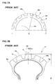
- a tread portion "a" of these tires has a single circular arc tread profile Pa having a tire shaft center “i” as the center of arc in a circumferential section parallel to the tire equatorial plane Cc.
- Ground-contacting top surface “bs” of each of blocks “b” which constitute a block pattern is formed into a convex arc profile shape along the tread profile Pa in the circumferential section.
- the tread portion "a” In the meridional cross section perpendicular to the tire equatorial plane Cc, the tread portion "a” has a smooth convex arc profile Pb connecting both tread edges Te, Te.
- the top surface “bs” of each of the blocks “b” is formed into a convex arc profile shape along the tread profile Pb in the meridional cross section.
- the blocks "b” having a top surface “bs” of such a profile shape have a problem that the ground contact pressure at the periphery of the block top surface "bs” becomes low as compared with a central portion of the block top surface "bs", so the edge effect brought by block edges is not effectively exhibited and no satisfactory traction performance is obtained.
- an off-road motorcycle tire having a block pattern comprising a plurality of blocks defined by tread grooves in a tread portion, wherein:
- the blocks include center blocks disposed on the tire equator and outer blocks disposed along both tread edges, wherein:
- wall surfaces facing in the circumferential direction of tire comprise an upper wall portion located on the block top surface side, and a lower wall portion located on the groove bottom side, and the inclination angle ⁇ 1 of the upper wall portion with respect to a normal line to the block top surface is smaller than the inclination angle ⁇ 2 of the lower wall portion with respect to the normal line to the block top surface.
- wall surfaces facing in the axial direction of tire comprise an upper wall portion located on the block top surface side, and a lower wall portion located on the groove bottom side, and the inclination angle ⁇ 1 of the upper wall portion with respect to a normal line to the block top surface is smaller than the inclination angle ⁇ 2 of the lower wall portion with respect to the normal line to the block top surface.
- the blocks include center blocks disposed on the tire equator and outer blocks disposed along both tread edges, and the inclination angle ⁇ 1 of an axially orienting block wall for the outer blocks is smaller than the inclination angle ⁇ 1 for the center blocks. It is further preferable that the inclination angle ⁇ 2 of an axially orienting block wall for the outer blocks is larger than the inclination angle ⁇ 2 for the center blocks.
- a part or all of the blocks may have a recess portion in a center portion of the top surface of each block.
- top surface denotes a profile of the top surface of each block in the circumferential section which passes through the centroid of the block top surface and is parallel to the tire equatorial plane.
- meridional profile denotes a profile of the top surface of each block in the meridional section which passes through the centroid of the block top surface and is perpendicular to the tire equatorial plane.
- the "dimensions" and so on of respective parts or portions of a tire denotes values measured under a normal inner pressure condition, namely those measured with respect to the tire mounted on a normal rim and inflated to a normal inner pressure under no loading, unless otherwise noted.
- the term "normal rim” denotes a rim defined for every tire in a standardizing system on which the tire is based and is, for example, the “standard rim” in JATMA, the “Design Rim” in TRA and the “Measuring Rim” in ETRTO.
- normal inner pressure denotes an air pressure defined for every tire in the standardizing system and is, for example, the “maximum air pressure” in JATMA, the maximum value recited in the table of "Tire Load Limits at Various Cold Inflation Pressures” in TRA, and the “Inflation Pressure” in ETRTO.
- the blocks are formed to have a block surface such that the circumferential profile of the top surface of each block is rectilinear or in the form of a circular arc having a radius of curvature larger than half of the outer diameter of a tire, e.g., a radius of curvature of 500 mm or more, decrease in ground contact pressure at the periphery of the top surface of each block can be suppressed to enhance the edge effect and accordingly the traction performance can be enhanced.
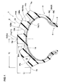
- Fig. 1 is a meridional section view of an off-road motorcycle tire under the normal inner pressure condition according to an embodiment of the present invention
- Fig. 2 is a development showing a tread pattern of the tire shown in Fig. 1.
- Fig. 1 corresponds to a sectional view taken on line A-A in Fig. 2 .
- off-road motorcycle tire 1 in this embodiment includes a tread portion 2, a pair of sidewall portions 3,3 extending radially inwardly from the both edges of the tread portion 2, and a pair of bead portions 4,4 which are located at radially inner edges of the sidewall portions 4,4 and to which a rim (not shown) is attached.
- the tire 1 shown in this embodiment is a motorcycle tire suitable for motocross racing.
- tread portion 2 is formed a tread pattern (shown in Fig. 2 ) comprising a large number of blocks 11 defined by tread grooves 10.
- Each of the blocks 11 has a top surface 12 which comes into contact with a road, and wall surfaces 15 extending from the peripheral edges 13 of the top surface 12 to the bottoms 14 of the tread grooves 10. From the viewpoints of driving performance and braking performance, an approximately quadrangular shape is preferred for the top surface 12.
- the tread portion 2 In a meridional section perpendicular to the tire equatorial plane Cc and including a tire rotation shaft, the tread portion 2 has a smooth curved tread profile Pb extending in a convex circular arc shape from the tire equator C toward both tread edges Te.
- This tread profile Pb in the meridional direction i.e., axial direction of tire
- the tread profile Pb has a circular arc shape such that radial distance Lr from an equatorial point Cp (a point of the arc on the tire equator C) to the tread edge Te is from 30 to 40 mm, and the camber which is defined by Lr/Lj ratio is from 0.35 to 0.75 in which Lj is an axial distance from the equatorial point Cp (tire equator C) to the tread edge Te. Since the tire 1 has such a tread profile, banking at a large angle is possible at the time of cornering.
- the tread edges Te are located axially outward of the sidewalls 3 to hang over them.
- the tire 1 is reinforced by a toroidal carcass 6 and a tread-reinforcing layer 7 which is disposed radially outward of the carcass 6 and radially inward of the tread portion 2.
- the carcass 6 comprises at least one carcass ply 6A which comprises a main portion 6a toroidally extending between a pair of bead cores 5,5 disposed in opposing bead portions 4,4, and turnup portions 6b that extend from the both ends of the main body portion 6a and are turned up around the bead cores 5 from the axially inside to the axially outside of the tire to thereby anchor the carcass ply.
- a carcass 6 is preferred, from the viewpoint of tire lateral rigidity, one having a bias structure comprising at least two carcass plies of organic fiber cords which are arranged at an angle of, for example, 15 to 45° with respect to the circumferential direction of tire.
- a carcass having a radial structure comprising at least one carcass ply of the carcass cords which are arranged at an angle of, for example, 75 to 90° with respect to the circumferential direction of tire.
- the tread-reinforcing layer 7 comprises at least one reinforcement ply 7A (in this embodiment, two plies 7A) of organic fiber cords arranged at an angle of, for example, 15 to 45° with respect to the circumferential direction of tire.
- the tread-reinforcing layer 7 is disposed to reinforce the tread portion 2 over an approximately overall width of the tread portion 2, thereby securing a required tread rigidity.
- the blocks 11 are relatively sparsely provided, whereby the blocks deeply dig into a soft terrain such as mud to exhibit a high driving force.
- a sparsely distributed block disposition is also useful for preventing clogging of grooves with mud, since tread grooves 10 between the blocks 11 become wide.
- the sparsely distributed disposition of blocks 11 can be quantitatively defined by a land ratio Sb/S of the total surface area Sb of top surfaces 12 of all blocks 11 to the whole surface area S of the outer surface of the tread portion 2 (i.e., surface area of an imaginary tread in which all tread grooves 10 are filled up).
- the land ratio Sb/S is preferably from 10 to 30 %.
- the height BH of the blocks 11 is from 7 to 19 mm.
- the block height BH is defined as a height of tread groove 10 from the groove bottom 14 at the axial edge 12Be of the block top surface 12, or as a height of tread groove 10 from the groove bottom 14 at the tread profile Pb in the meridional direction.
- the blocks 11 include, at least, center blocks 11c disposed on the tire equator C and outer blocks 11e disposed along both tread edges Te.
- the center blocks 11c have centroids G of their top surfaces 12 on the tire equator C.
- the term "center block” 11c encompasses all blocks having a top surface 12 at least a part of which is located on the tire equator C.
- the outer blocks 11e are blocks disposed along the tread edges Te, and denote blocks that an axially outer edge 13b of peripheral edges 13 of the block top surface 12 constitutes the tread edge 11e.
- Middle blocks 11m may be further disposed between the center blocks 11c and the outer blocks 11e, in other words, between the tire equator C and each tread edge Te.
- middle blocks 11m blocks having a centroid G of their top surface 12 in shoulder regions YS,YS having a width of 12.5 % of a tread-developed width TW from the tread edge Te are defined as middle outer blocks 11mo, and blocks having a centroid G of their top surface 12 in a crown region YC located between the shoulder regions YS,YS are defined as middle inner blocks 11mi.
- the circumferential profile 16 of the top surface 12 of each of the blocks 11c, 11m and 11e in the circumferential section Ka which passes through the centroid G of the top surface 12 and is parallel to the tire equatorial plane Cc is rectilinear or in the form of a circular arc having a radius Ra of curvature of at least 500 mm.
- the mark "Pa” denotes a tread profile in the form of a single arc which has a tire shaft center as the center of curvature in the circumferential section Ka of each block and which passes through circumferentially outer edges 12Ae of the top surface 12.
- tread profile PaO on the tire equatorial plane Cc has a radius "ra" of curvature identical to halt of the tire diameter D (D/2).
- the blocks 11c, 11m and 11e are formed to have the top surface 12 with a circumferential profile 16 in the form of a straight line or a circular arc having a larger radius of curvature than the radius "ra" of curvature of the tread profile PaO, e.g., a radius of curvature of at least 500 mm, in each circumferential section Ka.
- the blocks have such a circumferential section profile, a center portion of the top surface 12 of each block dents radially inwardly from the tread profile Pa, so the ground contact pressure at the circumferentially outer edge points 12Ae of the top surface 12 can be enhanced relatively. Therefore, the edge effect at the circumferentially outer edge points 12Ae, namely the edge effect of circumferential edges 13a of the top surface 12, can be enhanced to improve the traction performance.
- the circumferential profile 16 may be in the form of any of a convex circular arc having a curvature center inside the tire, a concave circular arc having a curvature center outside the tire and a straight line.
- the shape of the circumferential profile 16 (convex circular arc profile, concave circular arc profile and rectilinear profile) and the radius Ra of curvature can be set for each of blocks 11c, 11 m and 11e. However, from the viewpoints of steering stability and uneven wear, it is preferable to form the circumferential profile of all blocks 11c, 11m and 11e to have the same shape and the same radius of curvature.
- the meridional profile 17 of the top surface 12 of each of the blocks 11c, 11m and 11e in the meridian section Kb which passes through the centroid G of the top surface 12 and is perpendicular to the tire equatorial plane Cc is rectilinear or in the form of a circular arc having a radius Rb of curvature.
- the center blocks 11c are formed to have a meridional section profile 17c in the form of a straight line or a circular arc having a radius Rbc of curvature of at least 500 mm.
- the outer blocks 11e are formed to have a meridional section profile 17e in the form of a circular arc having a radius Rbe of curvature smaller than the radius Rbc of curvature of the meridional profile 17c of the center blocks 11c.
- the middle outer blocks 11mo are formed to have a meridional section profile 17mo in the form of a circular arc having a radius Rbmo of curvature smaller than the radius Rbc of curvature of the meridional profile 17c of the center blocks 11c.
- the middle inner blocks 11 mi are formed to have a meridional section profile 17mi in the form of a straight line or a circular arc having a radius Rbmi of curvature of at least 500 mm. At least radii Rbc and Rbmi are larger than the radius "rb" of curvature of the meridional section tread profile Pb.
- the edge effect at the axial edges 13b of the top surface 12 can be enhanced by forming the meridian cross section profile of the blocks in such a manner, so the side slip is suppressed to improve the cornering performance.
- the radius Rbe of curvature of the outer blocks 11e and the radius Rbmo of curvature of the middle outer blocks 11mo are from 30 to 100 mm, respectively. If these radii of curvature are less than 30 mm, a ground-contacting feel tends to be impaired, and if they are more than 100 mm, smoothness in banking of motorcycle during cornering is impaired and the cornering performance tends to be deteriorated.
- the radii Rbe and Rbmo of curvature are more preferably from 30 to 70 mm for tires having a width of less than 110 mm, and from 50 to 100 mm for tires having a width of 110 mm or more.
- the meridional cross section profile 17 In case of forming the meridional cross section profile 17 into a circular arc shape, it is formed into a convex circular arc having a curvature center inside the tire, from the viewpoint of cornering performance.
- each of wall surfaces 15a facing in the circumferential direction of tire is composed of an upper wall portion 20 located on the block top surface 12 side, and a lower wall portion 21 located on the groove bottom 14 side.
- the inclination angle ⁇ 1 of the upper wall portion 20 with respect to a normal line to the block top surface 12 is made smaller than the inclination angle ⁇ 2 of the lower wall portion 21 with respect to the normal line to the block top surface 12.
- the reason is that the circumferentially outer edges 13a are sharpened by forming the upper wall portion 20 at a steep angle, whereby the edge effect can be further enhanced.
- the upper wall portion 20 is steep, the blocks 11 can deeply dig into mud or the like.
- the grip performance can be further enhanced on both a hard terrain and a soft terrain such as mud or sand.
- the inclination angle ⁇ 2 of the lower wall portion 21 is made larger than the inclination angle ⁇ 1 of the upper wall portion 20, a root portion of block 11 is reinforced and accordingly the block rigidity can be maintained.
- the inclination angle ⁇ 1 of the upper wall portion 20 is from 0 to 10°, and the inclination angle ⁇ 2 of the lower wall portion 21 is from 7 to 25°. Further, it is preferable that the difference ⁇ 2 - ⁇ 1 between the inclination angles ⁇ 1 and ⁇ 2 is 5° or more. If the inclination angle ⁇ 1 is more than 10°, further improvement in edge effect brought by steep wall is not obtained, and if the inclination angle ⁇ 1 is less than 0°, the edges 13a become too sharp, so chipping of edges is easy to occur. Also, if the inclination angle ⁇ 2 is less than 7°, reinforcement of blocks is not sufficient, and if the inclination angle ⁇ 2 is more than 25°, the digging property of the blocks into mud is impaired.
- the height "ha” of the upper wall portion 20 is preferably from 0.05 to 0.5 times the block height BH. If the height "ha" is less than 0.05 times, the effect of improving the grip performance based on the upper wall portion 20 is not exhibited, and if the height "ha" is more than 0.5 times, the reinforcement effect based on the lower wall portion 21 is not exhibited.
- each of wall surfaces 15b facing in the axial direction of tire is composed of an upper wall portion 22 located on the block top surface 12 side, and a lower wall portion 23 located on the groove bottom 14 side, in the same manner as the block walls 15a circumferentially opposing each other.
- the inclination angle ⁇ 1 of the upper wall portion 22 with respect to the normal line to the block top surface 12 is smaller than the inclination angle ⁇ 2 of the lower wall portion 23 with respect to the normal line to the block top surface 12. Further, it is preferable that the difference ⁇ 2 - ⁇ 1 is 5° or more.
- the height "hb" of the upper wall portion 22 is preferably from 0.05 to 0.5 times the block height BH.
- the inclination angle ⁇ 1 ( ⁇ 1e) of the axially orienting block wall 15b for the outer blocks 11e is smaller than the inclination angle ⁇ 1 ( ⁇ 1c) for the center blocks 11c, whereby the lateral grip performance can be more effectively improved.
- the outer blocks 11e tend to lack the lateral rigidity. Therefore, for the purpose of maintaining the lateral rigidity of the outer blocks 11e, preferably the inclination angle ⁇ 2 ( ⁇ 2e) for the outer blocks 11e is made larger than the inclination angle ⁇ 2 ( ⁇ 2c) for the center blocks 11c.
- the inclination angle ⁇ 1c is from 0 to 10°, and the inclination angle ⁇ 2c is from 7 to 25°.
- the inclination angle ⁇ 1e of the upper wall portion 22 is from -5 to -3°, and the inclination angle ⁇ 2e of the lower wall portion 23 is from 15 to 25°.
- the mark "-" as used herein for the inclination angle ⁇ denotes that the block wall 15 is inclined in a direction that the block width increases toward the block top surface 12.
- the middle blocks 11m it is preferable that the inclination angle ⁇ 1m is identical to or less than the inclination angle ⁇ 1c, and the inclination angle ⁇ 2m is identical to or more than the inclination angle ⁇ 2e and is identical to or less than the inclination angle ⁇ 2c.
- the middle inner blocks 11 mi have an inclination angle ⁇ 1mi of -3 to 0° and an inclination angle ⁇ 2mi of 7 to 15°.
- the middle outer blocks 11mo have an inclination angle ⁇ 1mo of -5 to -3°, and the inclination angle ⁇ 2c is from 7 to 25°. is from 0 to 10° and an inclination angle ⁇ 2mo of 15 to 25°.
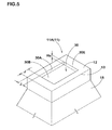
- the blocks 11 may include recessed blocks 11A as shown in Fig. 5 , wherein a recess portion 30 is formed in a center portion of the top surface 12 of each block.
- all blocks 11 formed in the tread portion are the recessed blocks 11A, but of course a part of the blocks 11 may be the recessed blocks 11A.
- only the center blocks 11c, or only the middle blocks 11m, or only the outer blocks 11e, are replaced with the recessed blocks 11A.
- Combination of non-recessed blocks 11 and recessed blocks 11A can be suitably set.
- the recess portion 30 is a recess surrounded by edge lines 30E parallel to the peripheral edges 13 of the block top surface 12.
- the recess portion 30 is effective for improving the grip performance, since mud or the like gets into the recess.
- the space J between a ridge line 30E and a peripheral edge 13 is from 3 to 10 mm, preferably 5 to 7 mm. If the space J is less than 3 mm, the rigidity at the peripheral edges 13 is impaired to lower the edge effect. If the space J is more than 10 mm, the recess portion 30 becomes small and the effect to be brought by formation of the recess portion can not be expected.
- step faces 30A extend from the ridge lines 30E to bottom 30B.
- the height Ha of the step faces 30A is from 1 to 3 mm, preferably 1.5 to 2.0 mm. If the height Ha is less than 1 mm, mud does not sufficiently get into the recess, and if it is more than 3 mm, the block rigidity is lowered and the edge effect tends to lower.
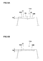
- the cross section profile of the bottom 30B of the recess portion 30 may be, besides flat surface, convex circular arc surface ( Fig. 6B ) and concave circular arc surface ( Fig. 6A ).
- a convex circular arc bottom it is required that a peak portion thereof does not protrude radially outward of the block top surface 12.
- a concave circular arc bottom it is preferable from the viewpoint of maintaining the block rigidity that the depth Hb from the top surface 12 of a deepest portion of the recess is at most 5 mm.
- the blocks 11 according to this embodiment have a tendency that the block edges tend to be easily worn away since the edge effect is enhanced. Therefore, it is preferable to use, as a rubber for constituting the blocks 11, a rubber harder than conventionally used rubbers, e.g., a rubber having a Durometer Type A hardness of 75 to 80. Conventionally used rubbers usually have a Durometer Type A hardness of 70 to 74.
- Off-road tires for motorcycle having a tire structure shown in Fig. 1 and having a tread patter shown in Fig. 2 as a basic patter were manufactured based on the specifications shown in Table 1. Other specifications of the tires are substantially common to all tires. The performances of the tires such as traction performance, grip performance and ground-contacting feel were evaluated by an actual running test.
- a test tire was attached to the rear wheel of a 450 cc motocross motorcycle under the conditions of rim 19x2.15 and internal pressure 80 kPa, and was run on a motocross test course by a professional test driver.
- the traction performance, grip performance and ground-contacting feeling were evaluated by driver's feeling.
- the results are shown by an index to the result of Comparative Example 1 regarded as 100. The larger the value, the better the performances.
- same tire size 90/100-21 57M, rim 21 ⁇ 1.60, internal pressure 80 kPa was used as a front wheel tire.
Abstract
Description
- The present invention relates to a motorcycle tire suitable for off-road traveling, and more particularly to an off-road motorcycle tire having a steering stability improved by devising the circumferential profile shape of the surface of blocks provided in the tread surface.
- Tires for traveling on unpaved roads or rough terrain, e.g., off-road racing motorcycle tires, are provided with a block type tread pattern in which a plurality of blocks defined by tread grooves are formed in a tread portion, in order to secure a good traction performance on rough terrain, as disclosed for example in
JP-A-11-078427 - In general, as shown in
Figs. 7A and 7B , a tread portion "a" of these tires has a single circular arc tread profile Pa having a tire shaft center "i" as the center of arc in a circumferential section parallel to the tire equatorial plane Cc. Ground-contacting top surface "bs" of each of blocks "b" which constitute a block pattern is formed into a convex arc profile shape along the tread profile Pa in the circumferential section. The radius "ra" of curvature of the tread profile Pa in the circumferential section at the equatorial plane Cc is identical with half of the outer diameter D of the tire (ra = D/2). In the meridional cross section perpendicular to the tire equatorial plane Cc, the tread portion "a" has a smooth convex arc profile Pb connecting both tread edges Te, Te. The top surface "bs" of each of the blocks "b" is formed into a convex arc profile shape along the tread profile Pb in the meridional cross section. - However, the blocks "b" having a top surface "bs" of such a profile shape have a problem that the ground contact pressure at the periphery of the block top surface "bs" becomes low as compared with a central portion of the block top surface "bs", so the edge effect brought by block edges is not effectively exhibited and no satisfactory traction performance is obtained.
- Accordingly, it is an object of the present invention to provide an off-road motorcycle tire having an improved traction performance.
- This and other objects of the present invention will become apparent from the description hereinafter.
- It has been found that when the blocks are formed so that the profile of the top surface of each block in the circumferential section is in the form of a straight line or a circular arc having a radius of curvature larger than half of the outer diameter of a tire, e.g., a radius Ra of curvature of at least 500 mm, decrease in ground contact pressure at the periphery of the top surface of each block can be suppressed to enhance the edge effect and accordingly the traction performance can be enhanced.
- In accordance with the present invention, there is provided an off-road motorcycle tire having a block pattern comprising a plurality of blocks defined by tread grooves in a tread portion, wherein:
- each of the blocks includes a top surface which comes into contact with a road, and wall surfaces extending from the periphery of the top surface to the bottoms of the tread grooves, and
- each block has a circumferential profile of the top surface in the form of a straight line or a circular arc having a radius Ra of curvature of at least 500 mm, in which the circumferential profile denotes a profile in the circumferential section which passes through the centroid of the top surface and is parallel to the tire equatorial plane.
- In an embodiment of the present invention, the blocks include center blocks disposed on the tire equator and outer blocks disposed along both tread edges, wherein:
- the center blocks have a meridional profile of the top surface in the form of a straight line or a circular arc having a radius Rbc of curvature of at least 500 mm, in which the meridional profile denotes a profile in the meridional section which passes through the centroid of the top surface and is perpendicular to the tire equatorial plane, and
- the outer blocks have a meridional profile of the top surface in the form of a circular arc having a radius Rbe of curvature smaller than the radius Rbc of curvature of the meridional profile of the center blocks.
- It is preferable that among the block wall surfaces mentioned above, wall surfaces facing in the circumferential direction of tire comprise an upper wall portion located on the block top surface side, and a lower wall portion located on the groove bottom side, and the inclination angle θ1 of the upper wall portion with respect to a normal line to the block top surface is smaller than the inclination angle θ2 of the lower wall portion with respect to the normal line to the block top surface.
- It is also preferable that among the block wall surfaces mentioned above, wall surfaces facing in the axial direction of tire comprise an upper wall portion located on the block top surface side, and a lower wall portion located on the groove bottom side, and the inclination angle α1 of the upper wall portion with respect to a normal line to the block top surface is smaller than the inclination angle α2 of the lower wall portion with respect to the normal line to the block top surface.
- It is preferable that the blocks include center blocks disposed on the tire equator and outer blocks disposed along both tread edges, and the inclination angle α1 of an axially orienting block wall for the outer blocks is smaller than the inclination angle α1 for the center blocks. It is further preferable that the inclination angle α2 of an axially orienting block wall for the outer blocks is larger than the inclination angle α2 for the center blocks.
- A part or all of the blocks may have a recess portion in a center portion of the top surface of each block.
- The term "circumferential profile" of top surface as used herein denotes a profile of the top surface of each block in the circumferential section which passes through the centroid of the block top surface and is parallel to the tire equatorial plane. Also, the term "meridional profile" of top surface as used herein denotes a profile of the top surface of each block in the meridional section which passes through the centroid of the block top surface and is perpendicular to the tire equatorial plane.
- In the specification, the "dimensions" and so on of respective parts or portions of a tire denotes values measured under a normal inner pressure condition, namely those measured with respect to the tire mounted on a normal rim and inflated to a normal inner pressure under no loading, unless otherwise noted. The term "normal rim" denotes a rim defined for every tire in a standardizing system on which the tire is based and is, for example, the "standard rim" in JATMA, the "Design Rim" in TRA and the "Measuring Rim" in ETRTO. The term "normal inner pressure" denotes an air pressure defined for every tire in the standardizing system and is, for example, the "maximum air pressure" in JATMA, the maximum value recited in the table of "Tire Load Limits at Various Cold Inflation Pressures" in TRA, and the "Inflation Pressure" in ETRTO.
- Since in the present invention the blocks are formed to have a block surface such that the circumferential profile of the top surface of each block is rectilinear or in the form of a circular arc having a radius of curvature larger than half of the outer diameter of a tire, e.g., a radius of curvature of 500 mm or more, decrease in ground contact pressure at the periphery of the top surface of each block can be suppressed to enhance the edge effect and accordingly the traction performance can be enhanced.
-
-
Fig. 1 is a cross sectional view of an off-road motorcycle tire illustrating an embodiment of the present invention; -
Fig. 2 is a development showing a tread pattern of the motorcycle tire ofFig. 1 ; -
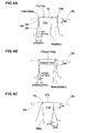
Figs. 3A, 3B and 3C are a circumferential cross section view of a block for showing a profile shape of the top surface of the block in the circumferential direction; -
Figs. 4A, 4B and 4C are a meridional cross section view of a block for showing a profile shape of the top surface of the block in the meridional direction; -
Fig. 5 is a perspective view illustrating a recessed block; -
Figs. 6A and 6B are a cross sectional view of a recessed block for illustrating the bottom of a recess portion; and -
Figs. 7A and 7B are circumferential and meridional section views for showing the profile shape of the top surface of each block of a conventional tire. - An embodiment of the present invention will now be explained with reference to the accompanying drawings.
Fig. 1 is a meridional section view of an off-road motorcycle tire under the normal inner pressure condition according to an embodiment of the present invention, andFig. 2 is a development showing a tread pattern of the tire shown inFig. 1. Fig. 1 corresponds to a sectional view taken on line A-A inFig. 2 . - As shown in
Fig. 1 , off-road motorcycle tire 1 in this embodiment includes atread portion 2, a pair ofsidewall portions tread portion 2, and a pair of bead portions 4,4 which are located at radially inner edges of the sidewall portions 4,4 and to which a rim (not shown) is attached. The tire 1 shown in this embodiment is a motorcycle tire suitable for motocross racing. - In
tread portion 2 is formed a tread pattern (shown inFig. 2 ) comprising a large number ofblocks 11 defined bytread grooves 10. Each of theblocks 11 has atop surface 12 which comes into contact with a road, andwall surfaces 15 extending from theperipheral edges 13 of thetop surface 12 to thebottoms 14 of thetread grooves 10. From the viewpoints of driving performance and braking performance, an approximately quadrangular shape is preferred for thetop surface 12. - In a meridional section perpendicular to the tire equatorial plane Cc and including a tire rotation shaft, the
tread portion 2 has a smooth curved tread profile Pb extending in a convex circular arc shape from the tire equator C toward both tread edges Te. This tread profile Pb in the meridional direction (i.e., axial direction of tire) is defined as a profile line smoothly connecting axial edges 12Be oftop surfaces 12 of respective blocks in the meridional section. In this embodiment shown in the drawings, the tread profile Pb has a circular arc shape such that radial distance Lr from an equatorial point Cp (a point of the arc on the tire equator C) to the tread edge Te is from 30 to 40 mm, and the camber which is defined by Lr/Lj ratio is from 0.35 to 0.75 in which Lj is an axial distance from the equatorial point Cp (tire equator C) to the tread edge Te. Since the tire 1 has such a tread profile, banking at a large angle is possible at the time of cornering. The tread edges Te are located axially outward of thesidewalls 3 to hang over them. - The tire 1 is reinforced by a
toroidal carcass 6 and a tread-reinforcinglayer 7 which is disposed radially outward of thecarcass 6 and radially inward of thetread portion 2. - The
carcass 6 comprises at least onecarcass ply 6A which comprises amain portion 6a toroidally extending between a pair ofbead cores portions 6b that extend from the both ends of themain body portion 6a and are turned up around thebead cores 5 from the axially inside to the axially outside of the tire to thereby anchor the carcass ply. As acarcass 6 is preferred, from the viewpoint of tire lateral rigidity, one having a bias structure comprising at least two carcass plies of organic fiber cords which are arranged at an angle of, for example, 15 to 45° with respect to the circumferential direction of tire. Of course, however, there can be used, as occasion demands, a carcass having a radial structure comprising at least one carcass ply of the carcass cords which are arranged at an angle of, for example, 75 to 90° with respect to the circumferential direction of tire. - The tread-reinforcing
layer 7 comprises at least onereinforcement ply 7A (in this embodiment, twoplies 7A) of organic fiber cords arranged at an angle of, for example, 15 to 45° with respect to the circumferential direction of tire. The tread-reinforcinglayer 7 is disposed to reinforce thetread portion 2 over an approximately overall width of thetread portion 2, thereby securing a required tread rigidity. - As to a block pattern provided in the
tread portion 2, theblocks 11 are relatively sparsely provided, whereby the blocks deeply dig into a soft terrain such as mud to exhibit a high driving force. A sparsely distributed block disposition is also useful for preventing clogging of grooves with mud, sincetread grooves 10 between theblocks 11 become wide. The sparsely distributed disposition ofblocks 11 can be quantitatively defined by a land ratio Sb/S of the total surface area Sb oftop surfaces 12 of allblocks 11 to the whole surface area S of the outer surface of the tread portion 2 (i.e., surface area of an imaginary tread in which alltread grooves 10 are filled up). If the land ratio is too small, the driving force on a hard road or a medium road is decreased, and if the land ratio is too large, the driving force on a soft road such as mud is decreased. From such points of view, the land ratio Sb/S is preferably from 10 to 30 %. - If the height BH (shown in
Fig. 1 ) ofblock 11 is too small, there is a tendency that sufficient driving or braking force is not obtained on unpaved road or rough terrain, and if the height BH is too large, a large bending moment acts on the root of theblock 11 at the time of driving or braking, so the durability of theblock 11 tends to deteriorate. From such points of view, it is preferable that the height BH of theblocks 11 is from 7 to 19 mm. Herein, the block height BH is defined as a height oftread groove 10 from the groove bottom 14 at the axial edge 12Be of the blocktop surface 12, or as a height oftread groove 10 from the groove bottom 14 at the tread profile Pb in the meridional direction. - As shown in
Fig. 2 , theblocks 11 include, at least, center blocks 11c disposed on the tire equator C andouter blocks 11e disposed along both tread edges Te. In this embodiment, the center blocks 11c have centroids G of theirtop surfaces 12 on the tire equator C. However, the term "center block" 11c encompasses all blocks having atop surface 12 at least a part of which is located on the tire equator C. Theouter blocks 11e are blocks disposed along the tread edges Te, and denote blocks that an axiallyouter edge 13b ofperipheral edges 13 of the blocktop surface 12 constitutes thetread edge 11e.Middle blocks 11m may be further disposed between the center blocks 11c and theouter blocks 11e, in other words, between the tire equator C and each tread edge Te. Ofmiddle blocks 11m, blocks having a centroid G of theirtop surface 12 in shoulder regions YS,YS having a width of 12.5 % of a tread-developed width TW from the tread edge Te are defined as middle outer blocks 11mo, and blocks having a centroid G of theirtop surface 12 in a crown region YC located between the shoulder regions YS,YS are defined as middle inner blocks 11mi. - In the tire 1 according to this embodiment, as shown in
Figs. 3A to 3C in an enlarged manner, thecircumferential profile 16 of thetop surface 12 of each of theblocks top surface 12 and is parallel to the tire equatorial plane Cc is rectilinear or in the form of a circular arc having a radius Ra of curvature of at least 500 mm. In the drawings, the mark "Pa" denotes a tread profile in the form of a single arc which has a tire shaft center as the center of curvature in the circumferential section Ka of each block and which passes through circumferentially outer edges 12Ae of thetop surface 12. In particular, tread profile PaO on the tire equatorial plane Cc has a radius "ra" of curvature identical to halt of the tire diameter D (D/2). - In the present invention, the
blocks top surface 12 with acircumferential profile 16 in the form of a straight line or a circular arc having a larger radius of curvature than the radius "ra" of curvature of the tread profile PaO, e.g., a radius of curvature of at least 500 mm, in each circumferential section Ka. - Since the blocks have such a circumferential section profile, a center portion of the
top surface 12 of each block dents radially inwardly from the tread profile Pa, so the ground contact pressure at the circumferentially outer edge points 12Ae of thetop surface 12 can be enhanced relatively. Therefore, the edge effect at the circumferentially outer edge points 12Ae, namely the edge effect ofcircumferential edges 13a of thetop surface 12, can be enhanced to improve the traction performance. - The
circumferential profile 16 may be in the form of any of a convex circular arc having a curvature center inside the tire, a concave circular arc having a curvature center outside the tire and a straight line. The shape of the circumferential profile 16 (convex circular arc profile, concave circular arc profile and rectilinear profile) and the radius Ra of curvature can be set for each ofblocks blocks - As shown in
Figs. 4A, 4B and 4C in an enlarged manner, themeridional profile 17 of thetop surface 12 of each of theblocks top surface 12 and is perpendicular to the tire equatorial plane Cc is rectilinear or in the form of a circular arc having a radius Rb of curvature. - Of these, the center blocks 11c are formed to have a
meridional section profile 17c in the form of a straight line or a circular arc having a radius Rbc of curvature of at least 500 mm. On the other hand, theouter blocks 11e are formed to have ameridional section profile 17e in the form of a circular arc having a radius Rbe of curvature smaller than the radius Rbc of curvature of themeridional profile 17c of the center blocks 11c. As to themiddle blocks 11m, the middle outer blocks 11mo are formed to have a meridional section profile 17mo in the form of a circular arc having a radius Rbmo of curvature smaller than the radius Rbc of curvature of themeridional profile 17c of the center blocks 11c. The middleinner blocks 11 mi are formed to have a meridional section profile 17mi in the form of a straight line or a circular arc having a radius Rbmi of curvature of at least 500 mm. At least radii Rbc and Rbmi are larger than the radius "rb" of curvature of the meridional section tread profile Pb. - The edge effect at the
axial edges 13b of thetop surface 12 can be enhanced by forming the meridian cross section profile of the blocks in such a manner, so the side slip is suppressed to improve the cornering performance. It is preferable that the radius Rbe of curvature of theouter blocks 11e and the radius Rbmo of curvature of the middle outer blocks 11mo are from 30 to 100 mm, respectively. If these radii of curvature are less than 30 mm, a ground-contacting feel tends to be impaired, and if they are more than 100 mm, smoothness in banking of motorcycle during cornering is impaired and the cornering performance tends to be deteriorated. The radii Rbe and Rbmo of curvature are more preferably from 30 to 70 mm for tires having a width of less than 110 mm, and from 50 to 100 mm for tires having a width of 110 mm or more. - In case of forming the meridional
cross section profile 17 into a circular arc shape, it is formed into a convex circular arc having a curvature center inside the tire, from the viewpoint of cornering performance. - As shown in
Figs. 3A to 3C , among the wall surfaces 15 ofblocks wall surfaces 15a facing in the circumferential direction of tire is composed of anupper wall portion 20 located on the blocktop surface 12 side, and alower wall portion 21 located on the groove bottom 14 side. - The inclination angle θ1 of the
upper wall portion 20 with respect to a normal line to the blocktop surface 12 is made smaller than the inclination angle θ2 of thelower wall portion 21 with respect to the normal line to the blocktop surface 12. The reason is that the circumferentiallyouter edges 13a are sharpened by forming theupper wall portion 20 at a steep angle, whereby the edge effect can be further enhanced. Further, since theupper wall portion 20 is steep, theblocks 11 can deeply dig into mud or the like. Thus, the grip performance can be further enhanced on both a hard terrain and a soft terrain such as mud or sand. Also, since the inclination angle θ2 of thelower wall portion 21 is made larger than the inclination angle θ1 of theupper wall portion 20, a root portion ofblock 11 is reinforced and accordingly the block rigidity can be maintained. - Specifically, as to the
blocks upper wall portion 20 is from 0 to 10°, and the inclination angle θ2 of thelower wall portion 21 is from 7 to 25°. Further, it is preferable that the difference θ2 - θ1 between the inclination angles θ1 and θ2 is 5° or more. If the inclination angle θ1 is more than 10°, further improvement in edge effect brought by steep wall is not obtained, and if the inclination angle θ1 is less than 0°, theedges 13a become too sharp, so chipping of edges is easy to occur. Also, if the inclination angle θ2 is less than 7°, reinforcement of blocks is not sufficient, and if the inclination angle θ2 is more than 25°, the digging property of the blocks into mud is impaired. - The height "ha" of the
upper wall portion 20 is preferably from 0.05 to 0.5 times the block height BH. If the height "ha" is less than 0.05 times, the effect of improving the grip performance based on theupper wall portion 20 is not exhibited, and if the height "ha" is more than 0.5 times, the reinforcement effect based on thelower wall portion 21 is not exhibited. - As shown in
Figs. 4A to 4C , among the wall surfaces 15 ofblocks upper wall portion 22 located on the blocktop surface 12 side, and alower wall portion 23 located on the groove bottom 14 side, in the same manner as theblock walls 15a circumferentially opposing each other. The inclination angle α1 of theupper wall portion 22 with respect to the normal line to the blocktop surface 12 is smaller than the inclination angle α2 of thelower wall portion 23 with respect to the normal line to the blocktop surface 12. Further, it is preferable that the difference α2 - α1 is 5° or more. The height "hb" of theupper wall portion 22 is preferably from 0.05 to 0.5 times the block height BH. Such axially orientingblock walls 15b are effective for enhancing the lateral grip performance to thereby further improve the cornering performance. - It is preferable that the inclination angle α1 (α1e) of the axially orienting
block wall 15b for theouter blocks 11e is smaller than the inclination angle α1 (α1c) for the center blocks 11c, whereby the lateral grip performance can be more effectively improved. In that case, however, theouter blocks 11e tend to lack the lateral rigidity. Therefore, for the purpose of maintaining the lateral rigidity of theouter blocks 11e, preferably the inclination angle α2 (α2e) for theouter blocks 11e is made larger than the inclination angle α2 (α2c) for the center blocks 11c. - Specifically, as to the center blocks 11c, it is preferable that the inclination angle α1c is from 0 to 10°, and the inclination angle α2c is from 7 to 25°. Further, as to the
outer blocks 11e, it is preferable that the inclination angle α1e of theupper wall portion 22 is from -5 to -3°, and the inclination angle α2e of thelower wall portion 23 is from 15 to 25°. The mark "-" as used herein for the inclination angle α denotes that theblock wall 15 is inclined in a direction that the block width increases toward the blocktop surface 12. - As to the
middle blocks 11m, it is preferable that the inclination angle α1m is identical to or less than the inclination angle α1c, and the inclination angle α2m is identical to or more than the inclination angle α2e and is identical to or less than the inclination angle α2c. In particular, it is preferable that the middleinner blocks 11 mi have an inclination angle α1mi of -3 to 0° and an inclination angle α2mi of 7 to 15°. Further, it is preferable that the middle outer blocks 11mo have an inclination angle α1mo of -5 to -3°, and the inclination angle α2c is from 7 to 25°. is from 0 to 10° and an inclination angle α2mo of 15 to 25°. - The
blocks 11 may include recessedblocks 11A as shown inFig. 5 , wherein arecess portion 30 is formed in a center portion of thetop surface 12 of each block. In the present embodiment, all blocks 11 formed in the tread portion are the recessedblocks 11A, but of course a part of theblocks 11 may be the recessedblocks 11A. For example, only the center blocks 11c, or only themiddle blocks 11m, or only theouter blocks 11e, are replaced with the recessedblocks 11A. Combination ofnon-recessed blocks 11 and recessedblocks 11A can be suitably set. - The
recess portion 30 is a recess surrounded byedge lines 30E parallel to theperipheral edges 13 of the blocktop surface 12. Therecess portion 30 is effective for improving the grip performance, since mud or the like gets into the recess. The space J between aridge line 30E and aperipheral edge 13 is from 3 to 10 mm, preferably 5 to 7 mm. If the space J is less than 3 mm, the rigidity at theperipheral edges 13 is impaired to lower the edge effect. If the space J is more than 10 mm, therecess portion 30 becomes small and the effect to be brought by formation of the recess portion can not be expected. - In the
recess portion 30 shown in this embodiment, step faces 30A (walls of recess portion 30) extend from theridge lines 30E tobottom 30B. The height Ha of the step faces 30A is from 1 to 3 mm, preferably 1.5 to 2.0 mm. If the height Ha is less than 1 mm, mud does not sufficiently get into the recess, and if it is more than 3 mm, the block rigidity is lowered and the edge effect tends to lower. - As shown in
Figs. 6A and 6B , the cross section profile of the bottom 30B of therecess portion 30 may be, besides flat surface, convex circular arc surface (Fig. 6B ) and concave circular arc surface (Fig. 6A ). In case of a convex circular arc bottom, it is required that a peak portion thereof does not protrude radially outward of the blocktop surface 12. In case of a concave circular arc bottom, it is preferable from the viewpoint of maintaining the block rigidity that the depth Hb from thetop surface 12 of a deepest portion of the recess is at most 5 mm. - The
blocks 11 according to this embodiment have a tendency that the block edges tend to be easily worn away since the edge effect is enhanced. Therefore, it is preferable to use, as a rubber for constituting theblocks 11, a rubber harder than conventionally used rubbers, e.g., a rubber having a Durometer Type A hardness of 75 to 80. Conventionally used rubbers usually have a Durometer Type A hardness of 70 to 74. - While a preferable embodiment of the present invention has been described with reference to the drawings, it goes without saying that the present invention is not limited to only such an embodiment and various changes and modifications may be made.
- The present invention is more specifically described and explained by means of the following examples. It is to be understood that the present invention is not limited to these examples.
- Off-road tires for motorcycle (size: 120/80-19 63M) having a tire structure shown in
Fig. 1 and having a tread patter shown inFig. 2 as a basic patter were manufactured based on the specifications shown in Table 1. Other specifications of the tires are substantially common to all tires. The performances of the tires such as traction performance, grip performance and ground-contacting feel were evaluated by an actual running test. - A test tire was attached to the rear wheel of a 450 cc motocross motorcycle under the conditions of rim 19x2.15 and internal pressure 80 kPa, and was run on a motocross test course by a professional test driver. The traction performance, grip performance and ground-contacting feeling were evaluated by driver's feeling. The results are shown by an index to the result of Comparative Example 1 regarded as 100. The larger the value, the better the performances. In all tests, same tire (size 90/100-21 57M, rim 21×1.60, internal pressure 80 kPa) was used as a front wheel tire.
- The results are shown in Table 1.
Table 1 Com. Ex. 1 Com. Ex.2 Com. Ex.3 Ex. 1 Ex. 2 Ex. 3 Ex. 4 Ex. 5 Ex. 6 Ex. 7 Circumferential section profile arc arc arc arc arc flat flat flat flat flat Radius of curvature Ra (mm) 340 340 340 500 500 ∞ ∞ ∞ ∞ ∞ Meridional section profile arc arc arc arc arc flat flat flat flat flat Radius of curvature Rbc (mm) 70 80 340 300 500 ∞ ∞ ∞ ∞ ∞ Radius of curvature Rbmi (mm) 70 80 340 300 500 ∞ ∞ ∞ ∞ ∞ Radius of curvature Rbmo (mm) 70 80 340 300 500 ∞ ∞ ∞ ∞ ∞ Radius of curvature Rbe (mm) 70 80 340 300 500 ∞ ∞ ∞ ∞ ∞ Circumferentially facing block walls Angle θ1 of upper wall portion 5° 5° 5° 5° 5° 5° 5° 5° 10° 5° Angle θ2 of lower wall portion 15° 15° 15° 15° 15° 15° 15° 15° 20° 15° Axially facing block walls Angle of upper wall portion α1c 10° 10° 10° 10° 10° 10° 10° 5° 5° 10° α1mo -3° -3° -3° -3° -3° -3° -3° -3° -3° -3° α1mi 0° 0° 0° 0° 0° 0° 0° 0° 0° 0° α1e -3° -3° -3° -3° -3° -3° -3° -3° -3° -5° Angle of lower wall portion α2c 15° 15° 15° 15° 15° 15° 15° 10° 10° 15° α2mo 20° 20° 20° 20° 20° 20° 20° 20° 20° 20° α2mi 15° 15° 15° 15° 15° 15° 15° 15° 15° 15° α2e 15° 15° 15° 15° 15° 15° 15° 15° 15° 5° Presence of recess portion yes yes yes yes yes yes yes yes yes yes Space J (mm) 6 6 6 6 6 6 10 6 6 6 Height Ha (mm) 2 2 2 2 2 2 2 2 2 2 Traction performance 100 105 105 120 130 140 140 130 150 140 Grip performance 100 105 110 110 130 140 120 140 130 110 Ground-contacting feel 100 105 110 110 120 125 120 120 120 110
Claims (7)
- An off-road motorcycle tire having a block pattern comprising a plurality of blocks defined by tread grooves in a tread portion, wherein:each of the blocks includes a top surface which comes into contact with a road, and wall surfaces extending from the periphery of the top surface to the bottoms of the tread grooves, andeach block has a circumferential profile of the top surface in the form of a straight line or a circular arc having a radius Ra of curvature of at least 500 mm, in which the circumferential profile denotes a profile in the circumferential section which passes through the centroid of the top surface and is parallel to the tire equatorial plane.
- The off-road motorcycle tire of claim 1, wherein the blocks include center blocks disposed on the tire equator and outer blocks disposed along both tread edges, wherein:the center blocks have a meridional profile of the top surface in the form of a straight line or a circular arc having a radius Rbc of curvature of at least 500 mm, in which the meridional profile denotes a profile in the meridional section which passes through the centroid of the top surface and is perpendicular to the tire equatorial plane, andthe outer blocks have a meridional profile of the top surface in the form of a circular arc having a radius Rbe of curvature smaller than the radius Rbc of curvature of the meridional profile of the center blocks.
- The off-road motorcycle tire of claim 1 or 2, wherein among said wall surfaces, wall surfaces facing in the circumferential direction of tire comprise an upper wall portion located on the block top surface side and a lower wall portion located on the groove bottom side, and the inclination angle θ1 of the upper wall portion with respect to a normal line to the block top surface is smaller than the inclination angle θ2 of the lower wall portion with respect to the normal line to the block top surface.
- The off-road motorcycle tire of any one of claims 1 to 3, wherein among said wall surfaces, wall surfaces facing in the axial direction of tire comprise an upper wall portion located on the block top surface side and a lower wall portion located on the groove bottom side, and the inclination angle αl of the upper wall portion with respect to a normal line to the block top surface is smaller than the inclination angle α2 of the lower wall portion with respect to the normal line to the block top surface.
- The off-road motorcycle tire of claim 4, wherein the blocks include center blocks disposed on the tire equator and outer blocks disposed along both tread edges, and the inclination angle α1 of an axially orienting block wall for the outer blocks is smaller than the inclination angle α1 for the center blocks.
- The off-road motorcycle tire of claim 5, wherein the inclination angle α2 of an axially orienting block wall for the outer blocks is larger than the inclination angle α2 for the center blocks.
- The off-road motorcycle tire of any one of claims 1 to 6, wherein said blocks include at least one recessed block having a recess portion in a center portion of the top surface.
Applications Claiming Priority (1)
| Application Number | Priority Date | Filing Date | Title |
|---|---|---|---|
| JP2007128166A JP4344392B2 (en) | 2007-05-14 | 2007-05-14 | Motorcycle tires for running on rough terrain |
Publications (2)
| Publication Number | Publication Date |
|---|---|
| EP1992504A1 true EP1992504A1 (en) | 2008-11-19 |
| EP1992504B1 EP1992504B1 (en) | 2011-07-27 |
Family
ID=39671380
Family Applications (1)
| Application Number | Title | Priority Date | Filing Date |
|---|---|---|---|
| EP08008456A Expired - Fee Related EP1992504B1 (en) | 2007-05-14 | 2008-05-05 | Motorcycle tire for off-road traveling |
Country Status (4)
| Country | Link |
|---|---|
| US (1) | US7874330B2 (en) |
| EP (1) | EP1992504B1 (en) |
| JP (1) | JP4344392B2 (en) |
| CN (1) | CN101306633B (en) |
Cited By (5)
| Publication number | Priority date | Publication date | Assignee | Title |
|---|---|---|---|---|
| EP2251213A1 (en) * | 2008-02-19 | 2010-11-17 | Bridgestone Corporation | Pneumatic tire for motorcycle |
| EP2390114A1 (en) * | 2010-05-28 | 2011-11-30 | Sumitomo Rubber Industries, Ltd. | Motorcycle tire for running on rough terrain |
| CN102686414A (en) * | 2009-12-30 | 2012-09-19 | 米其林企业总公司 | Tire tread for a two-wheel vehicle |
| EP2650145A1 (en) * | 2012-04-09 | 2013-10-16 | Sumitomo Rubber Industries, Ltd. | Pneumatic tire for running on rough terrain |
| WO2014207126A1 (en) * | 2013-06-28 | 2014-12-31 | Compagnie Generale Des Etablissements Michelin | Tyre tread surface for a two-wheeled vehicle |
Families Citing this family (19)
| Publication number | Priority date | Publication date | Assignee | Title |
|---|---|---|---|---|
| USD608724S1 (en) | 2009-03-16 | 2010-01-26 | Trek Bicycle Corporation | Bicycle tire tread |
| JP4951043B2 (en) * | 2009-08-25 | 2012-06-13 | 住友ゴム工業株式会社 | Pneumatic tire |
| FR2954221B1 (en) * | 2009-12-17 | 2012-03-16 | Michelin Soc Tech | TIRE WITH IMPROVED RUNNING PERFORMANCE |
| JP5161933B2 (en) | 2010-07-28 | 2013-03-13 | 住友ゴム工業株式会社 | Motorcycle tires for running on rough terrain |
| WO2012087272A1 (en) * | 2010-12-20 | 2012-06-28 | Michelin Recherche Et Technique, S.A. | Tread block with features for improved thermal wear |
| JP5480922B2 (en) * | 2012-01-26 | 2014-04-23 | 住友ゴム工業株式会社 | Pneumatic tire and manufacturing method thereof |
| US8905097B2 (en) | 2012-02-01 | 2014-12-09 | Bridgestone Americas Tire Operations, Llc | Agricultural tire tread |
| JP5564071B2 (en) | 2012-05-18 | 2014-07-30 | 住友ゴム工業株式会社 | Motorcycle tires for running on rough terrain |
| JP6093637B2 (en) * | 2013-04-24 | 2017-03-08 | 株式会社ブリヂストン | tire |
| US10850567B2 (en) | 2013-04-24 | 2020-12-01 | Bridgestone Corporation | Tire |
| JP5981949B2 (en) | 2014-02-18 | 2016-08-31 | 住友ゴム工業株式会社 | Pneumatic tire |
| JP6241936B2 (en) * | 2014-02-24 | 2017-12-06 | 住友ゴム工業株式会社 | Motorcycle tire for rough terrain |
| JP7007925B2 (en) * | 2018-01-22 | 2022-01-25 | Toyo Tire株式会社 | Pneumatic tires |
| JP7087427B2 (en) * | 2018-02-08 | 2022-06-21 | 住友ゴム工業株式会社 | Motorcycle tires |
| FR3088246B3 (en) * | 2018-11-14 | 2020-10-30 | Michelin & Cie | AGRICULTURAL VEHICLE TREAD |
| JP7290056B2 (en) * | 2019-04-10 | 2023-06-13 | 住友ゴム工業株式会社 | tire |
| JP2021151824A (en) * | 2020-03-24 | 2021-09-30 | 住友ゴム工業株式会社 | Motorcycle tire for irregular ground running |
| JP2022178198A (en) * | 2021-05-19 | 2022-12-02 | 住友ゴム工業株式会社 | Off-road traveling tire |
| JP2023148526A (en) * | 2022-03-30 | 2023-10-13 | 住友ゴム工業株式会社 | Tire pair for motorcycle |
Citations (7)
| Publication number | Priority date | Publication date | Assignee | Title |
|---|---|---|---|---|
| GB2005200A (en) * | 1977-09-11 | 1979-04-19 | Sumitomo Rubber Ind | Wheel tire tread |
| JPH02136306A (en) * | 1988-11-17 | 1990-05-24 | Sumitomo Rubber Ind Ltd | Tire for motor-cycle |
| JPH03204305A (en) | 1990-01-05 | 1991-09-05 | Sumitomo Rubber Ind Ltd | Tire for motorcycle |
| JPH1178427A (en) | 1997-09-02 | 1999-03-23 | Sumitomo Rubber Ind Ltd | Pneumatic tire |
| JP2004351956A (en) * | 2003-05-27 | 2004-12-16 | Bridgestone Corp | Pneumatic tire and mounting method of pneumatic tire |
| JP2005199927A (en) | 2004-01-16 | 2005-07-28 | Marui:Kk | Bicycle tire |
| EP1923236A1 (en) * | 2006-11-15 | 2008-05-21 | Sumitomo Rubber Industries, Ltd. | Pneumatic tire for off-road travelling |
Family Cites Families (9)
| Publication number | Priority date | Publication date | Assignee | Title |
|---|---|---|---|---|
| JPS6112411A (en) | 1984-06-27 | 1986-01-20 | Yokohama Rubber Co Ltd:The | Tire for motorcycle |
| JPS6192903A (en) | 1984-10-13 | 1986-05-10 | Sumitomo Rubber Ind Ltd | Tyre pattern of on-and-off running motorcycle |
| US5377734A (en) * | 1991-12-13 | 1995-01-03 | Klein Bicycle Corporation | High efficiency all terrain bicycle or motorcycle tire |
| JPH07215016A (en) * | 1994-02-01 | 1995-08-15 | Toyo Tire & Rubber Co Ltd | Low noise pneumatic radial tire |
| JPH0891024A (en) | 1994-09-22 | 1996-04-09 | Bridgestone Corp | Pneumatic tire for bicycle |
| JP2002046424A (en) | 2000-08-02 | 2002-02-12 | Bridgestone Corp | Pneumatic tire |
| JP4820483B2 (en) | 2000-11-17 | 2011-11-24 | 東洋ゴム工業株式会社 | Pneumatic radial tire |
| JP4034550B2 (en) * | 2001-11-13 | 2008-01-16 | 住友ゴム工業株式会社 | Pneumatic tire |
| KR100604077B1 (en) * | 2003-11-06 | 2006-07-25 | 한국타이어 주식회사 | Tread pattern structure for off road tire |
-
2007
- 2007-05-14 JP JP2007128166A patent/JP4344392B2/en not_active Expired - Fee Related
-
2008
- 2008-05-05 EP EP08008456A patent/EP1992504B1/en not_active Expired - Fee Related
- 2008-05-13 US US12/153,070 patent/US7874330B2/en not_active Expired - Fee Related
- 2008-05-14 CN CN2008100947345A patent/CN101306633B/en not_active Expired - Fee Related
Patent Citations (7)
| Publication number | Priority date | Publication date | Assignee | Title |
|---|---|---|---|---|
| GB2005200A (en) * | 1977-09-11 | 1979-04-19 | Sumitomo Rubber Ind | Wheel tire tread |
| JPH02136306A (en) * | 1988-11-17 | 1990-05-24 | Sumitomo Rubber Ind Ltd | Tire for motor-cycle |
| JPH03204305A (en) | 1990-01-05 | 1991-09-05 | Sumitomo Rubber Ind Ltd | Tire for motorcycle |
| JPH1178427A (en) | 1997-09-02 | 1999-03-23 | Sumitomo Rubber Ind Ltd | Pneumatic tire |
| JP2004351956A (en) * | 2003-05-27 | 2004-12-16 | Bridgestone Corp | Pneumatic tire and mounting method of pneumatic tire |
| JP2005199927A (en) | 2004-01-16 | 2005-07-28 | Marui:Kk | Bicycle tire |
| EP1923236A1 (en) * | 2006-11-15 | 2008-05-21 | Sumitomo Rubber Industries, Ltd. | Pneumatic tire for off-road travelling |
Cited By (10)
| Publication number | Priority date | Publication date | Assignee | Title |
|---|---|---|---|---|
| EP2251213A1 (en) * | 2008-02-19 | 2010-11-17 | Bridgestone Corporation | Pneumatic tire for motorcycle |
| EP2251213A4 (en) * | 2008-02-19 | 2012-04-04 | Bridgestone Corp | Pneumatic tire for motorcycle |
| US8875755B2 (en) | 2008-02-19 | 2014-11-04 | Bridgestone Corporation | Pneumatic tire for motorcycle |
| CN102686414A (en) * | 2009-12-30 | 2012-09-19 | 米其林企业总公司 | Tire tread for a two-wheel vehicle |
| CN102686414B (en) * | 2009-12-30 | 2015-02-11 | 米其林企业总公司 | Tire tread for a two-wheel vehicle |
| EP2390114A1 (en) * | 2010-05-28 | 2011-11-30 | Sumitomo Rubber Industries, Ltd. | Motorcycle tire for running on rough terrain |
| US8869848B2 (en) | 2010-05-28 | 2014-10-28 | Sumitomo Rubber Industries, Ltd. | Motorcycle tire for running on rough terrain |
| EP2650145A1 (en) * | 2012-04-09 | 2013-10-16 | Sumitomo Rubber Industries, Ltd. | Pneumatic tire for running on rough terrain |
| WO2014207126A1 (en) * | 2013-06-28 | 2014-12-31 | Compagnie Generale Des Etablissements Michelin | Tyre tread surface for a two-wheeled vehicle |
| FR3007692A1 (en) * | 2013-06-28 | 2015-01-02 | Michelin & Cie | TIRE TREAD FOR A TWO-WHEELED VEHICLE |
Also Published As
| Publication number | Publication date |
|---|---|
| US20080283167A1 (en) | 2008-11-20 |
| EP1992504B1 (en) | 2011-07-27 |
| CN101306633B (en) | 2012-01-25 |
| US7874330B2 (en) | 2011-01-25 |
| JP2008279996A (en) | 2008-11-20 |
| CN101306633A (en) | 2008-11-19 |
| JP4344392B2 (en) | 2009-10-14 |
Similar Documents
| Publication | Publication Date | Title |
|---|---|---|
| EP1992504B1 (en) | Motorcycle tire for off-road traveling | |
| US8887778B2 (en) | Motorcycle tire for off-road traveling | |
| US11046118B2 (en) | Tire for two-wheel vehicle | |
| JP4272244B2 (en) | Pneumatic tire for running on rough terrain | |
| EP1923236B1 (en) | Pneumatic tire for off-road travelling | |
| EP2412547B1 (en) | Motorcycle tire for running on rough terrrain | |
| EP2423006B1 (en) | Motorcycle tire for running on rough terrain | |
| JP4733502B2 (en) | Pneumatic tire for running on rough terrain | |
| US8156976B2 (en) | Off-road tire for motorcycle | |
| JP4814980B2 (en) | Pneumatic tire for running on rough terrain | |
| JP4287877B2 (en) | Pneumatic tire for running on rough terrain | |
| US11541692B2 (en) | Tyre | |
| JP2020117020A (en) | tire | |
| CN115366581A (en) | Tire for running on rough terrain | |
| US11420478B2 (en) | Tyre | |
| EP3611037A1 (en) | Tyre for running on rough terrain | |
| JP4435917B2 (en) | Motorcycle tires | |
| EP3616945B1 (en) | Motorcycle tyre for off-road | |
| JP2966752B2 (en) | Pneumatic tire | |
| CN112566793A (en) | Tire for motorcycle | |
| JP2020189555A (en) | Motorcycle tire for travelling off road | |
| JP6631730B1 (en) | Pneumatic tire | |
| WO2020054767A1 (en) | Pneumatic tire | |
| JP2002019419A (en) | Pneumatic tire |
Legal Events
| Date | Code | Title | Description |
|---|---|---|---|
| PUAI | Public reference made under article 153(3) epc to a published international application that has entered the european phase |
Free format text: ORIGINAL CODE: 0009012 |
|
| AK | Designated contracting states |
Kind code of ref document: A1 Designated state(s): AT BE BG CH CY CZ DE DK EE ES FI FR GB GR HR HU IE IS IT LI LT LU LV MC MT NL NO PL PT RO SE SI SK TR |
|
| AX | Request for extension of the european patent |
Extension state: AL BA MK RS |
|
| 17P | Request for examination filed |
Effective date: 20090331 |
|
| 17Q | First examination report despatched |
Effective date: 20090430 |
|
| AKX | Designation fees paid |
Designated state(s): DE FR GB |
|
| GRAP | Despatch of communication of intention to grant a patent |
Free format text: ORIGINAL CODE: EPIDOSNIGR1 |
|
| GRAS | Grant fee paid |
Free format text: ORIGINAL CODE: EPIDOSNIGR3 |
|
| GRAA | (expected) grant |
Free format text: ORIGINAL CODE: 0009210 |
|
| AK | Designated contracting states |
Kind code of ref document: B1 Designated state(s): DE FR GB |
|
| REG | Reference to a national code |
Ref country code: GB Ref legal event code: FG4D |
|
| REG | Reference to a national code |
Ref country code: DE Ref legal event code: R096 Ref document number: 602008008463 Country of ref document: DE Effective date: 20110922 |
|
| PLBE | No opposition filed within time limit |
Free format text: ORIGINAL CODE: 0009261 |
|
| STAA | Information on the status of an ep patent application or granted ep patent |
Free format text: STATUS: NO OPPOSITION FILED WITHIN TIME LIMIT |
|
| 26N | No opposition filed |
Effective date: 20120502 |
|
| REG | Reference to a national code |
Ref country code: DE Ref legal event code: R097 Ref document number: 602008008463 Country of ref document: DE Effective date: 20120502 |
|
| PGFP | Annual fee paid to national office [announced via postgrant information from national office to epo] |
Ref country code: GB Payment date: 20150429 Year of fee payment: 8 |
|
| REG | Reference to a national code |
Ref country code: FR Ref legal event code: PLFP Year of fee payment: 9 |
|
| PGFP | Annual fee paid to national office [announced via postgrant information from national office to epo] |
Ref country code: FR Payment date: 20160412 Year of fee payment: 9 |
|
| GBPC | Gb: european patent ceased through non-payment of renewal fee |
Effective date: 20160505 |
|
| PG25 | Lapsed in a contracting state [announced via postgrant information from national office to epo] |
Ref country code: GB Free format text: LAPSE BECAUSE OF NON-PAYMENT OF DUE FEES Effective date: 20160505 |
|
| REG | Reference to a national code |
Ref country code: FR Ref legal event code: ST Effective date: 20180131 |
|
| PG25 | Lapsed in a contracting state [announced via postgrant information from national office to epo] |
Ref country code: FR Free format text: LAPSE BECAUSE OF NON-PAYMENT OF DUE FEES Effective date: 20170531 |
|
| PGFP | Annual fee paid to national office [announced via postgrant information from national office to epo] |
Ref country code: DE Payment date: 20190423 Year of fee payment: 12 |
|
| REG | Reference to a national code |
Ref country code: DE Ref legal event code: R119 Ref document number: 602008008463 Country of ref document: DE |
|
| PG25 | Lapsed in a contracting state [announced via postgrant information from national office to epo] |
Ref country code: DE Free format text: LAPSE BECAUSE OF NON-PAYMENT OF DUE FEES Effective date: 20201201 |