EP1990923B1 - Receiving device - Google Patents
Receiving device Download PDFInfo
- Publication number
- EP1990923B1 EP1990923B1 EP20080102914 EP08102914A EP1990923B1 EP 1990923 B1 EP1990923 B1 EP 1990923B1 EP 20080102914 EP20080102914 EP 20080102914 EP 08102914 A EP08102914 A EP 08102914A EP 1990923 B1 EP1990923 B1 EP 1990923B1
- Authority
- EP
- European Patent Office
- Prior art keywords
- subapparatus
- signal
- frequency
- reception apparatus
- antenna
- Prior art date
- Legal status (The legal status is an assumption and is not a legal conclusion. Google has not performed a legal analysis and makes no representation as to the accuracy of the status listed.)
- Not-in-force
Links
- 238000006243 chemical reaction Methods 0.000 claims description 9
- 230000005540 biological transmission Effects 0.000 claims description 2
- 230000001105 regulatory effect Effects 0.000 claims 1
- 238000010586 diagram Methods 0.000 description 2
- 238000011161 development Methods 0.000 description 1
- 230000018109 developmental process Effects 0.000 description 1
- 238000000034 method Methods 0.000 description 1
- 239000000203 mixture Substances 0.000 description 1
- 238000001228 spectrum Methods 0.000 description 1
- 239000013585 weight reducing agent Substances 0.000 description 1
Images
Classifications
-
- H—ELECTRICITY
- H04—ELECTRIC COMMUNICATION TECHNIQUE
- H04B—TRANSMISSION
- H04B1/00—Details of transmission systems, not covered by a single one of groups H04B3/00 - H04B13/00; Details of transmission systems not characterised by the medium used for transmission
- H04B1/06—Receivers
- H04B1/16—Circuits
- H04B1/18—Input circuits, e.g. for coupling to an antenna or a transmission line
-
- H—ELECTRICITY
- H04—ELECTRIC COMMUNICATION TECHNIQUE
- H04B—TRANSMISSION
- H04B1/00—Details of transmission systems, not covered by a single one of groups H04B3/00 - H04B13/00; Details of transmission systems not characterised by the medium used for transmission
- H04B1/06—Receivers
- H04B1/16—Circuits
- H04B1/26—Circuits for superheterodyne receivers
Definitions
- the invention relates to a receiving device, in particular a receiving device having at least two antennas for receiving signals via in each case one of the at least two antennas or for simultaneous reception of signals via at least two antennas, wherein the received signals are in the same frequency band or even on the same frequency.
- Receiving devices which have an antenna and receive and process signals via the antenna. Such receiving devices are, for example, radio receivers. Receiving devices are also known which have two antennas and can receive signals via both antennas. So is by the DE 101 15 053 A1 a radio receiver has become known, which has two antennas and in which the signals of the two antennas are switched to a respective receiver.
- US 5,784,418 A is a receiving circuit with two antennas known.
- the first antenna is connected to a first sub-device, wherein a second antenna is connected to a second sub-device.
- This receiver is intended for different frequency bands.
- the document DE 32 26 980 A1 describes a circuit for the reception of different frequency bands, namely VHF / UHF television bands with terrestrial antenna and the SHF range with satellite antenna. Between two circuit parts a single coaxial cable is available.
- the WO 03/103161 A2 discloses an arrangement with multiple antennas connected by bus interfaces to a bus.
- the receiving device is designed such that it is provided for receiving and evaluating signals with at least two antennas, wherein the receiving device comprises two sub-devices which are interconnected by means of electrical connection, wherein a signal of the first antenna without frequency conversion from the first sub-device is transmitted to the second sub-device and a signal of the second antenna is transmitted after a frequency conversion by a frequency mixer from the first sub-device to the second sub-device. It is particularly advantageous that the frequency conversion of the second signal is performed by a first frequency mixer having a first intermediate frequency ,
- the electrical connection for transmitting signals from the first sub-device to the second sub-device by a single cable which is designed as a two-pole cable and particularly advantageously as a coaxial cable.
- a frequency conversion of the first signal in the second sub-device takes place, wherein the frequency conversion is performed by a second frequency mixer whose second intermediate frequency is advantageously at least comparable or equal to the first intermediate frequency of the first frequency mixer.
- Comparable here means that an intermediate frequency does not differ by more than ten times the filter bandwidth from the other intermediate frequency.
- first and / or the second signal in the first sub-device is filtered by means of a filter before transmission to the second sub-device and / or amplified by means of an amplifier.
- a DC voltage is used for the electrical power supply of at least one of the sub-devices, wherein the DC voltage is preferably feasible via the electrical connection between the two sub-devices.
- control signals can be conducted via the electrical connection between the two sub-devices.
- An antenna structure is an assembly of at least two antennas.
- the signal of the first antenna and the signal of the second antenna of the antenna structure are removed. It may be advantageous if a signal path of the first and / or the second signal is designed with a selective impedance matching, wherein the selective impedance matching of a signal path is preferably carried out such that it does not extract energy from the other signal path in wide areas of the receiving band. This always improves the receiving power of the receiving system when the two receiving frequencies are sufficiently far from each other.
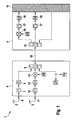
- FIG. 1 shows a block diagram of a receiving device 1 according to the invention with a first antenna 2 and a second antenna 3.
- the receiving device according to the invention according to FIG. 1 as a double receiving device, wherein also over two more outgoing number of antennas may be provided.
- the invention thus does not relate solely to a receiving device with two antennas.
- the embodiment is thus not limiting to the scope of protection. Instead of the two antennas, three, four or more antennas may be provided.
- the receiving device essentially consists of two sub-devices 4, 5, the sub-device 4 serving to condition the antenna signals, and the sub-system 5 serving as a receiving part of the device to which the antenna signals are supplied.
- the signal 6 received by the antenna 2 and to be forwarded is passed from the first sub-device 4 to the second sub-device 5 without frequency conversion.
- the signal 6 in the first sub-device can be filtered and / or amplified by means of a filter 7 and / or an amplifier 8.
- the thus possibly filtered and / or amplified signal 6 is fed via a frequency-selective in this example combiner 9 in the connection 10 between the first sub-device and the second sub-connection.
- the second antenna signal 11 of the second antenna 3 can be filtered and amplified by means of a filter 12 and / or amplifier 13 before it is mixed by means of a mixer 14 to an intermediate frequency.
- the mixed intermediate frequency signal (IF signal) is input to the connection 10 in addition to the non-mixed signal of the first antenna.
- the connection 10 may preferably be a cable or other electrical connection.
- the mixture to the intermediate frequency of the second signal 11 of the second antenna 3 is preferably carried out at the base of the second antenna or in the vicinity of one of the receiving antennas 2, 3 in the first sub-device 4.
- the signal is mixed to an intermediate frequency which is not in the received spectrum ,
- the two signals can be directed to the connection between the first sub-device and the second sub-device.
- the signal of the first antenna After passing through the frequency-selective splitter 15 in this example, the signal of the first antenna, which has not yet been mixed, is mixed in the mixer 16. Subsequently, the signals are further processed by means of the processing stages IF filter 17, amplifier / demodulator 18 and / or other subsequent stages 19.
- the device described above has between the two sub-devices 4,5 as subunits only an electrical connection 10, such as a cable o. on, by means of which both antenna signals are transmitted.
- an electrical connection 10 such as a cable o. on
- the variety of parts can be reduced and at the same time the susceptibility to interference can be reduced required interfaces and reduced by reducing the number of parts used. Also, this provides a weight reduction, which is particularly advantageous in the vehicle sector.
- the two mixers 14, 16 can be designed such that they have different intermediate frequencies or also have the same intermediate frequencies.
- both intermediate frequencies can be 10.7 MHz. In this case, there would be a cost advantage, since in this frequency range many standard components are offered, which could be used.
- Both antenna units can also receive the same frequencies, and yet two uncorrelated signals are available to the further signal processing, which signals are conducted via only one antenna line 10.
Landscapes
- Engineering & Computer Science (AREA)
- Computer Networks & Wireless Communication (AREA)
- Signal Processing (AREA)
- Input Circuits Of Receivers And Coupling Of Receivers And Audio Equipment (AREA)
- Radio Transmission System (AREA)
Description
Die Erfindung betrifft eine Empfangsvorrichtung, insbesondere eine Empfangsvorrichtung mit zumindest zwei Antennen zum Empfang von Signalen über jeweils eine der zumindest beiden Antennen oder zum gleichzeitigen Empfang von Signalen über zumindest zwei Antennen, wobei die empfangenen Signale im gleichen Frequenzband oder sogar auf der gleichen Frequenz liegen.The invention relates to a receiving device, in particular a receiving device having at least two antennas for receiving signals via in each case one of the at least two antennas or for simultaneous reception of signals via at least two antennas, wherein the received signals are in the same frequency band or even on the same frequency.
Es sind Empfangsvorrichtungen bekannt, die eine Antenne aufweisen und Signale über die Antenne empfangen und weiterverarbeiten. Solche Empfangsvorrichtungen sind beispielsweise Rundfunkempfänger. Auch sind Empfangsvorrichtungen bekannt, die zwei Antennen aufweisen und über beide Antennen Signale empfangen können. So ist durch die
Bei den Empfangsvorrichtungen nach dem Stand der Technik sind zwischen der Antenne und dem Empfänger jeweils pro Antenne eine elektrische Kabelverbindung notwendig, so dass dies eine Fehlerquelle birgt und Kosten verursacht. Weiterhin wird dadurch das Gewicht der Vorrichtung erhöht. Bei einer Anwendung im Fahrzeugbereich bedeutet somit die Verwendung von einem Kabel pro Antenne eine aufwändige Verkabelung, die auch Bauraum beansprucht, der in einem Fahrzeug stets knapp ist. Darüber hinaus bedeutet die Verwendung von einem Kabel pro Antenne eine grundsätzliche Fehlerquelle, da die Kabel typischer Weise mittels Steckverbindungen an den Schnittstellen verbunden werden müssen und solche Steckverbindungen eine generelle Fehlerquelle darstellen.In the prior art receiving devices, an electrical cable connection is required between the antenna and the receiver for each antenna, so that this involves a source of error and costs. Furthermore, this increases the weight of the device. In an application in the vehicle sector thus means the use from one cable per antenna, a complex wiring, which also takes up space, which is always scarce in a vehicle. In addition, the use of one cable per antenna means a fundamental source of error, since the cables typically have to be connected to the interfaces by means of plug connections and such connections represent a general source of error.
Aus der Druckschrift
Das Dokument
Die
Es ist die Aufgabe der vorliegenden Erfindung, eine Empfangsvorrichtung zu schaffen, welche ein geringeres Potenzial für Fehler darstellt und geringere Kosten verursacht und gleichzeitig ein geringeres Gewicht aufweist.It is the object of the present invention to provide a receiving device which presents a lower potential for errors and causes lower costs and at the same time has a lower weight.
Erfindungsgemäß wird die Aufgabe bezüglich der Vorrichtung gelöst mit den Merkmalen von Anspruch 1.According to the invention the object is achieved with respect to the device with the features of claim 1.
Die erfindungsgemäße Empfangsvorrichtung ist dabei derart ausgebildet, dass sie zum Empfangen und Auswerten von Signalen mit zumindest zwei Antennen versehen ist, wobei die Empfangsvorrichtung zwei Untervorrichtungen aufweist, die mittels elektrischer Verbindung miteinander verbunden sind, wobei ein Signal der ersten Antenne ohne Frequenzumsetzung von der ersten Untervorrichtung zu der zweiten Untervorrichtung übertragen wird und ein Signal der zweiten Antenne nach einer Frequenzumsetzung durch einen Frequenzmischer von der ersten Untervorrichtung zu der zweiten Untervorrichtung übertragen wird.Dabei ist es besonders vorteilhaft, dass die Frequenzumsetzung des zweiten Signals durch einen ersten Frequenzmischer mit einer ersten Zwischenfrequenz erfolgt.The receiving device according to the invention is designed such that it is provided for receiving and evaluating signals with at least two antennas, wherein the receiving device comprises two sub-devices which are interconnected by means of electrical connection, wherein a signal of the first antenna without frequency conversion from the first sub-device is transmitted to the second sub-device and a signal of the second antenna is transmitted after a frequency conversion by a frequency mixer from the first sub-device to the second sub-device. It is particularly advantageous that the frequency conversion of the second signal is performed by a first frequency mixer having a first intermediate frequency ,
Erfindungsgemäß erfolgt die elektrische Verbindung zur Übertragung von Signalen von der ersten Untervorrichtung zur zweiten Untervorrichtung durch ein einziges Kabel, das als zweipoliges Kabel und besonders vorteilhaft als Koaxialkabel ausgeführt ist.According to the invention, the electrical connection for transmitting signals from the first sub-device to the second sub-device by a single cable, which is designed as a two-pole cable and particularly advantageously as a coaxial cable.
Dabei ist es besonders zweckmäßig, wenn eine Frequenzumsetzung des ersten Signals in der zweiten Untervorrichtung erfolgt, wobei die Frequenzumsetzung durch einen zweiten Frequenzmischer erfolgt, dessen zweite Zwischenfrequenz vorteilhaft mit der ersten Zwischenfrequenz des ersten Frequenzmischers zumindest vergleichbar ist oder gleich ist. Vergleichbar bedeutet dabei, dass die eine Zwischenfrequenz nicht um mehr als zehnfache Filterbandbreite von der anderen Zwischenfrequenz abweicht.It is particularly expedient if a frequency conversion of the first signal in the second sub-device takes place, wherein the frequency conversion is performed by a second frequency mixer whose second intermediate frequency is advantageously at least comparable or equal to the first intermediate frequency of the first frequency mixer. Comparable here means that an intermediate frequency does not differ by more than ten times the filter bandwidth from the other intermediate frequency.
Besonders zweckmäßig, ist es, wenn das erste und/oder das zweite Signal in der ersten Untervorrichtung vor der Übertragung zur zweiten Untervorrichtung mittels eines Filters gefiltert und/oder mittels eines Verstärkers verstärkt wird.It is particularly expedient if the first and / or the second signal in the first sub-device is filtered by means of a filter before transmission to the second sub-device and / or amplified by means of an amplifier.
Auch ist es bei einem weiteren Ausführungsbeispiel zweckmäßig, wenn zur elektrischen Spannungsversorgung zumindest einer der Untervorrichtungen eine Gleichspannung verwendet wird, wobei die Gleichspannung vorzugsweise über die elektrische Verbindung zwischen den beiden Untervorrichtungen führbar ist. Weiterhin ist es zweckmäßig, wenn Steuersignale über die elektrische Verbindung zwischen den beiden Untervorrichtungen führbar sind.It is also expedient in another embodiment if a DC voltage is used for the electrical power supply of at least one of the sub-devices, wherein the DC voltage is preferably feasible via the electrical connection between the two sub-devices. Furthermore, it is expedient if control signals can be conducted via the electrical connection between the two sub-devices.
Auch ist es zweckmäßig, wenn die zumindest zwei Antennen eine gemeinsame Antennenstruktur bilden. Dabei ist eine Antennenstruktur eine Baueinheit von zumindest zwei Antennen.It is also expedient if the at least two antennas form a common antenna structure. An antenna structure is an assembly of at least two antennas.
Dabei ist es vorteilhaft, wenn das Signal der ersten Antenne und das Signal der zweiten Antenne der Antennenstruktur entnommen werden. Dabei kann es vorteilhaft sein, wenn ein Signalpfad des ersten und/oder des zweiten Signals mit einer selektiven Impedanzanpassung ausgeführt ist, wobei die selektive Impedanzanpassung eines Signalpfads vorzugsweise derart ausgeführt ist, dass er dem anderen Signalpfad in weiten Bereichen des Empfangsbandes keine Energie entzieht. Dies verbessert die Empfangsleistung des Empfangssystems immer dann, wenn die zwei Empfangsfrequenzen hinreichend weit voneinander entfernt sind.It is advantageous if the signal of the first antenna and the signal of the second antenna of the antenna structure are removed. It may be advantageous if a signal path of the first and / or the second signal is designed with a selective impedance matching, wherein the selective impedance matching of a signal path is preferably carried out such that it does not extract energy from the other signal path in wide areas of the receiving band. This always improves the receiving power of the receiving system when the two receiving frequencies are sufficiently far from each other.
Vorteilhafte Weiterbildungen sind in den Unteransprüchen beschrieben.Advantageous developments are described in the subclaims.
Nachstehend wird die Erfindung auf der Grundlage eines Ausführungsbeispiels anhand der Zeichnungen näher erläutert. Es zeigt:
- Fig. 1
- ein Bockschaltbild zur Erläuterung der erfindungsgemäßen Vorrichtung
- Fig. 1
- a block diagram for explaining the device according to the invention
Die
Die erfindungsgemäße Empfangsvorrichtung besteht im Wesentlichen aus zwei Untervorrichtungen 4,5, wobei die Untervorrichtung 4 dazu dient, die Antennensignale zu konditionieren und das Untersystem 5 dient als Empfangsteil der Vorrichtung, dem die Antennensignale zugeführt werden.The receiving device according to the invention essentially consists of two
Das von der Antenne 2 empfangene und weiterzuleitende Signal 6 wird ohne Frequenzumsetzung von der ersten Untervorrichtung 4 zur zweiten Untervorrichtung 5 geleitet. Allerdings kann das Signal 6 in der ersten Untervorrichtung mittels eines Filters 7 und/oder eines Verstärkers 8 gefiltert und/oder verstärkt werden. Das so gegebenenfalls gefilterte und/oder verstärkte Signal 6 wird über einen in diesem Beispiel frequenzselektiven Combiner 9 in die Verbindung 10 zwischen der ersten Untervorrichtung und der zweiten Unterverbindung eingespeist. Das zweite Antennensignal 11 der zweiten Antenne 3 kann mittels eines Filters 12 und/oder Verstärkers 13 gefiltert und verstärkt werden, bevor es mittels eines Mischers 14 auf eine Zwischenfrequenz gemischt wird. Das so gemischte Zwischenfrequenz-Signal (ZF-Signal) wird neben dem nicht gemischten Signal der ersten Antenne in die Verbindung 10 eingespeist. Die Verbindung 10 kann vorzugsweise ein Kabel oder eine anderweitige elektrische Verbindung sein.The signal 6 received by the
Die Mischung auf die Zwischenfrequenz des zweiten Signals 11 der zweiten Antenne 3 erfolgt vorzugsweise am Fußpunkt der zweiten Antenne oder in der Nähe einer der Empfangsantennen 2,3 in der ersten Untervorrichtung 4. Dabei wird das Signal auf eine Zwischenfrequenz gemischt, die nicht im Empfangsspektrum liegt.The mixture to the intermediate frequency of the
Dadurch können die beiden Signale auf die Verbindung zwischen der ersten Untervorrichtung und der zweiten Untervorrichtung geleitet werden.Thereby, the two signals can be directed to the connection between the first sub-device and the second sub-device.
Nach Durchlaufen des in diesem Beispiel frequenzselektiven Splitters 15 wird das bisher noch nicht gemischte Signal der ersten Antenne im Mischer 16 gemischt. Anschließend werden die Signale mittels der Verarbeitungsstufen ZF-Filter 17, Verstärker/Demodulator 18 und/oder anderen nachfolgenden Stufen 19 weiter verarbeitet.After passing through the frequency-
Alternativ kann zu dem oben beschriebenen auch eine Weiterleitung des Antennensignals der ersten Antenne zum Fußpunkt der zweiten Antenne oder eine Weiterleitung des Antennensignals der zweiten Antenne zum Fußpunkt der ersten Antenne und in beiden Fällen dann die entsprechende oben beschriebene Weiterverarbeitung erfolgen.Alternatively, to the above-described also a forwarding of the antenna signal of the first antenna to the base of the second antenna or a forwarding of the antenna signal of the second antenna to the base of the first antenna and in both cases then the corresponding further processing described above.
Die oben beschriebene Vorrichtung weist zwischen den beiden Untervorrichtungen 4,5 als Untereinheiten lediglich eine elektrische Verbindung 10, wie ein Kabel o.ä. auf, mittels welchem beide Antennensignale übertragen werden. Durch die Verwendung nur eines Kabels kann die Teilevielfalt reduziert werden und gleichzeitig kann die Störanfälligkeit durch die Reduzierung benötigter Schnittstellen und durch die Reduzierung der Anzahl verwendeter Teile vermindert werden. Auch erbringt dies eine Gewichtsminderung, die insbesondere im Fahrzeugbereich vorteilhaft ist.The device described above has between the two
Die beiden Mischer 14,16 können so ausgestaltet sein, dass sie unterschiedliche Zwischenfrequenzen aufweisen oder auch gleiche Zwischenfrequenzen aufweisen. So können beide Zwischenfrequenzen beispielsweise 10,7 MHz sein. In diesem Falle würde sich ein Kostenvorteil ergeben, da in diesem Frequenzbereich viele Standardbauteile angeboten werden, die verwendet werden könnten.The two
Auch können beide Antenneneinheiten die gleichen Frequenzen empfangen und dennoch stehen der weiteren Signalverarbeitung zwei unkorrelierte Signale zur Verfügung, die über nur eine Antennenleitung 10 geführt werden.Both antenna units can also receive the same frequencies, and yet two uncorrelated signals are available to the further signal processing, which signals are conducted via only one
Claims (13)
- Reception apparatus (1) for receiving and evaluating signals having at least two antennas (2, 3), wherein the apparatus (1) has two subapparatuses (4, 5) which are connected to one another by means of electrical connection (10), characterized in that both antennas (2, 3) are electrically connected only to the first subapparatus (4), in that a signal (6) from the first antenna (2) is transmitted without frequency conversion from the first subapparatus (4) to the second subapparatus (5) by the electrical connection (10) and a signal (11) from the second antenna (3) is transmitted with a frequency conversion by a frequency mixer (14) from the first subapparatus (4) to the second subapparatus (5) likewise by the electrical connection (10), in that a second frequency mixer (16) in the second subapparatus (5) performs frequency conversion only on the first signal (6), in that the electrical connection (10) for transmitting signals from the first subapparatus (4) to the second subapparatus (5) is made by a single cable, specifically by a two-pole cable or coaxial cable, and in that the received signals (6, 11) are in the same broadcast radio frequency band or even on the same frequency.
- Reception apparatus according to Claim 1, characterized in that the received signals are combined to form one signal after the processing in the second subapparatus (5).
- Reception apparatus according to one of the preceding claims, characterized in that a second intermediate frequency of the second frequency mixer (16) is at least comparable with or the same as a first intermediate frequency of the first frequency mixer (14).
- Reception apparatus according to one of Claims 1 and 2, characterized in that a second intermediate frequency of the second frequency mixer (16) and a first intermediate frequency of the first frequency mixer (14) are available, wherein one of the chosen intermediate frequencies is the baseband.
- Reception apparatus according to one of the preceding claims, characterized in that the first and/or the second signal (6, 11) is filtered and/or amplified in the first subapparatus (4) prior to transmission to the second subapparatus (5).
- Reception apparatus according to one of the preceding claims, characterized in that a filter means (7, 12) at the input of the first subapparatus (4) is designed as a bandpass filter and/or a mixing stage of the first frequency mixer (14) is in the form of a stage which mixes a fixed frequency and which converts all or some of the band to another frequency.
- Reception apparatus according to one of the preceding claims, characterized in that the gain implemented in the first subapparatus can be regulated on the basis of the received signal level.
- Reception apparatus according to one of the preceding claims, characterized in that a DC voltage is used for supplying electrical power to at least one of the subapparatuses (4, 5), wherein the DC voltage can preferably be routed via the electrical connection (10) between the two subapparatuses.
- Reception apparatus according to one of the preceding claims, characterized in that control signals can be routed via the electrical connection (10) between the two subapparatuses (4, 5).
- Reception apparatus according to one of the preceding claims, characterized in that the at least two antennas (2, 3) form a joint antenna structure.
- Reception apparatus according to Claim 10, characterized in that the signal from the first antenna (6) and the signal from the second antenna (11) are taken from the antenna structure.
- Reception apparatus according to Claim 11, characterized in that a signal path for the first or the second signal (6, 11) is designed to have selective impedance matching.
- Reception apparatus according to Claim 12, characterized in that the selective impedance matching of a signal path is designed such that it draws no power from the other signal path.
Applications Claiming Priority (1)
| Application Number | Priority Date | Filing Date | Title |
|---|---|---|---|
| DE200710022227 DE102007022227A1 (en) | 2007-05-11 | 2007-05-11 | receiving device |
Publications (3)
| Publication Number | Publication Date |
|---|---|
| EP1990923A2 EP1990923A2 (en) | 2008-11-12 |
| EP1990923A3 EP1990923A3 (en) | 2011-05-11 |
| EP1990923B1 true EP1990923B1 (en) | 2012-05-23 |
Family
ID=39674466
Family Applications (1)
| Application Number | Title | Priority Date | Filing Date |
|---|---|---|---|
| EP20080102914 Not-in-force EP1990923B1 (en) | 2007-05-11 | 2008-03-26 | Receiving device |
Country Status (2)
| Country | Link |
|---|---|
| EP (1) | EP1990923B1 (en) |
| DE (1) | DE102007022227A1 (en) |
Family Cites Families (6)
| Publication number | Priority date | Publication date | Assignee | Title |
|---|---|---|---|---|
| DE3226980A1 (en) * | 1982-07-19 | 1984-01-19 | Siemens AG, 1000 Berlin und 8000 München | Receiving arrangement for terrestrial television and satellite television and/or broadcasting |
| NL8901460A (en) * | 1989-06-08 | 1991-01-02 | Philips Nv | RECEIVER FOR TERRESTRIAL AM AND SATELLITE FM TV BROADCASTS. |
| GB9219486D0 (en) * | 1992-09-15 | 1992-10-28 | British Broadcasting Corp | Digital audio broadcasts |
| DE10115053A1 (en) | 2001-03-27 | 2002-10-24 | Bosch Gmbh Robert | Method and device for suppressing multipath interference in a receiver for electromagnetic waves |
| AU2003241092A1 (en) * | 2002-05-30 | 2003-12-19 | Koninklijke Philips Electronics N.V. | Radio frequency receiving and processing system |
| US7650173B2 (en) * | 2005-10-06 | 2010-01-19 | Flextronics Ap, Llc | Combined antenna module with single output |
-
2007
- 2007-05-11 DE DE200710022227 patent/DE102007022227A1/en not_active Withdrawn
-
2008
- 2008-03-26 EP EP20080102914 patent/EP1990923B1/en not_active Not-in-force
Also Published As
| Publication number | Publication date |
|---|---|
| EP1990923A2 (en) | 2008-11-12 |
| DE102007022227A1 (en) | 2008-11-13 |
| EP1990923A3 (en) | 2011-05-11 |
Similar Documents
| Publication | Publication Date | Title |
|---|---|---|
| DE60315917T2 (en) | Antenna with image rejection | |
| EP1701407A1 (en) | Multi-antenna receiving system in vehicles | |
| WO2018149459A1 (en) | Compensator, electronic circuit assembly for operating an antenna, and antenna device | |
| DE102010041612B4 (en) | Receiving arrangement of a motor vehicle | |
| EP1405370B1 (en) | Antenna connector arrangement, antenna signal splitter and method for receiver frequency control | |
| EP1832012B1 (en) | Antenna diversity device | |
| EP0128970A1 (en) | Four-port network for a monopulse-tracking microwave antenna | |
| EP1990923B1 (en) | Receiving device | |
| EP0740434B1 (en) | System for distributing satellite television signals in a community antenna system | |
| DE3543229C1 (en) | Distribution network for individual and community antenna systems | |
| DE4301648C1 (en) | Antenna plug socket for satellite and ground transmitter signals | |
| DE102014223883B4 (en) | Multi-channel wireless microphone system | |
| EP1076457B1 (en) | Satellite reception equipment with switchbox | |
| EP3738214A1 (en) | Systems for transporting externally received signals within a motor vehicle | |
| DE60115572T2 (en) | Method and circuit of a multiband receiver in a mobile telephone | |
| EP2634936B1 (en) | Feed system, in particular for receiving television or radio programming transmitted by satellite | |
| DE10236479B4 (en) | Mobile phone with power control | |
| EP2573989B1 (en) | Device for suppressing unwanted high frequency signals | |
| DE10219847A1 (en) | Method and device for generating at least one transponder in the satellite intermediate frequency level | |
| EP0985269B1 (en) | Highly decoupled high-frequency distribution network | |
| DE10326751B3 (en) | Receiving radio signals involves receiving signals in remote unit of receiving station via air interface, converting to intermediate frequency synchronized by reference signal from local unit | |
| EP1881703A1 (en) | Socket for telecommunication networks | |
| DE19528370C1 (en) | Aerial socket for cable television system | |
| DE202009018162U1 (en) | Multiswitch for satellite IF distribution | |
| DE202013006660U1 (en) | Feeding system, in particular for the reception of television and / or radio programs broadcast via satellite |
Legal Events
| Date | Code | Title | Description |
|---|---|---|---|
| PUAI | Public reference made under article 153(3) epc to a published international application that has entered the european phase |
Free format text: ORIGINAL CODE: 0009012 |
|
| AK | Designated contracting states |
Kind code of ref document: A2 Designated state(s): AT BE BG CH CY CZ DE DK EE ES FI FR GB GR HR HU IE IS IT LI LT LU LV MC MT NL NO PL PT RO SE SI SK TR |
|
| AX | Request for extension of the european patent |
Extension state: AL BA MK RS |
|
| PUAL | Search report despatched |
Free format text: ORIGINAL CODE: 0009013 |
|
| AK | Designated contracting states |
Kind code of ref document: A3 Designated state(s): AT BE BG CH CY CZ DE DK EE ES FI FR GB GR HR HU IE IS IT LI LT LU LV MC MT NL NO PL PT RO SE SI SK TR |
|
| AX | Request for extension of the european patent |
Extension state: AL BA MK RS |
|
| 17P | Request for examination filed |
Effective date: 20111111 |
|
| AKX | Designation fees paid |
Designated state(s): DE FR GB IT |
|
| GRAP | Despatch of communication of intention to grant a patent |
Free format text: ORIGINAL CODE: EPIDOSNIGR1 |
|
| GRAS | Grant fee paid |
Free format text: ORIGINAL CODE: EPIDOSNIGR3 |
|
| GRAA | (expected) grant |
Free format text: ORIGINAL CODE: 0009210 |
|
| AK | Designated contracting states |
Kind code of ref document: B1 Designated state(s): DE FR GB IT |
|
| REG | Reference to a national code |
Ref country code: GB Ref legal event code: FG4D Free format text: NOT ENGLISH |
|
| REG | Reference to a national code |
Ref country code: DE Ref legal event code: R096 Ref document number: 502008007252 Country of ref document: DE Effective date: 20120726 |
|
| PLBE | No opposition filed within time limit |
Free format text: ORIGINAL CODE: 0009261 |
|
| STAA | Information on the status of an ep patent application or granted ep patent |
Free format text: STATUS: NO OPPOSITION FILED WITHIN TIME LIMIT |
|
| 26N | No opposition filed |
Effective date: 20130226 |
|
| REG | Reference to a national code |
Ref country code: DE Ref legal event code: R097 Ref document number: 502008007252 Country of ref document: DE Effective date: 20130226 |
|
| PGFP | Annual fee paid to national office [announced via postgrant information from national office to epo] |
Ref country code: GB Payment date: 20150324 Year of fee payment: 8 |
|
| REG | Reference to a national code |
Ref country code: FR Ref legal event code: PLFP Year of fee payment: 9 |
|
| GBPC | Gb: european patent ceased through non-payment of renewal fee |
Effective date: 20160326 |
|
| PG25 | Lapsed in a contracting state [announced via postgrant information from national office to epo] |
Ref country code: GB Free format text: LAPSE BECAUSE OF NON-PAYMENT OF DUE FEES Effective date: 20160326 |
|
| REG | Reference to a national code |
Ref country code: FR Ref legal event code: PLFP Year of fee payment: 10 |
|
| REG | Reference to a national code |
Ref country code: FR Ref legal event code: PLFP Year of fee payment: 11 |
|
| PGFP | Annual fee paid to national office [announced via postgrant information from national office to epo] |
Ref country code: FR Payment date: 20190326 Year of fee payment: 12 Ref country code: IT Payment date: 20190321 Year of fee payment: 12 |
|
| PGFP | Annual fee paid to national office [announced via postgrant information from national office to epo] |
Ref country code: DE Payment date: 20190520 Year of fee payment: 12 |
|
| REG | Reference to a national code |
Ref country code: DE Ref legal event code: R119 Ref document number: 502008007252 Country of ref document: DE |
|
| PG25 | Lapsed in a contracting state [announced via postgrant information from national office to epo] |
Ref country code: DE Free format text: LAPSE BECAUSE OF NON-PAYMENT OF DUE FEES Effective date: 20201001 Ref country code: FR Free format text: LAPSE BECAUSE OF NON-PAYMENT OF DUE FEES Effective date: 20200331 |
|
| PG25 | Lapsed in a contracting state [announced via postgrant information from national office to epo] |
Ref country code: IT Free format text: LAPSE BECAUSE OF NON-PAYMENT OF DUE FEES Effective date: 20200326 |