EP1990716A1 - System and method for device skinning - Google Patents
System and method for device skinning Download PDFInfo
- Publication number
- EP1990716A1 EP1990716A1 EP08155835A EP08155835A EP1990716A1 EP 1990716 A1 EP1990716 A1 EP 1990716A1 EP 08155835 A EP08155835 A EP 08155835A EP 08155835 A EP08155835 A EP 08155835A EP 1990716 A1 EP1990716 A1 EP 1990716A1
- Authority
- EP
- European Patent Office
- Prior art keywords
- portable electronic
- commands
- electronic device
- definition file
- ide
- Prior art date
- Legal status (The legal status is an assumption and is not a legal conclusion. Google has not performed a legal analysis and makes no representation as to the accuracy of the status listed.)
- Ceased
Links
Images


Classifications
-
- G—PHYSICS
- G06—COMPUTING; CALCULATING OR COUNTING
- G06F—ELECTRIC DIGITAL DATA PROCESSING
- G06F9/00—Arrangements for program control, e.g. control units
- G06F9/06—Arrangements for program control, e.g. control units using stored programs, i.e. using an internal store of processing equipment to receive or retain programs
- G06F9/44—Arrangements for executing specific programs
- G06F9/451—Execution arrangements for user interfaces
Definitions
- the present disclosure relates to apparatuses and methods for programming a computing device.
- IDE integrated development environment
- JSEclipse from Adobe Systems Romania, formerly known as InterAKT Bdul.án Milea, nr 2H, et 1, ZIP 061344, Bucharest, Romania, based on Eclipse from the Eclipse Foundation, Inc. 102 Centrepointe Drive, Ottawa, Ontario, Canada, K2G 6B1.
- Another example is Microsoft Visual Studio from Microsoft Corporation of 205 108th Ave. NE, Suite 400, Bellevue, WA 98004.
- Screen size and shape varies significantly between portable electronic devices.
- devices often use particular user interface themes that impact the appearance of software applications.
- Screen controls such as buttons and dropdown lists, for example, are painted in a different manner depending on the device.
- software application designers perform multiple design iterations before the software application appears as intended on a targeted device. It is therefore desirable to improve the design process for portable electronic device software applications.
- a plugin for a Rapid Application Development Tool including: a set of commands for defining an appearance of a UI design window in the Rapid Application Development Tool, the appearance of the application design window simulating a display screen of a portable electronic device and the set of commands being related to one type of portable electronic device.
- a method for building an application in a Rapid Application Development tool including: selecting a skin corresponding to a portable electronic device type; launching a UI design window in the Rapid Application Development Tool, an appearance of the application design window simulating a portable electronic device having the portable electronic device type; and building the application in the Rapid Application Development Tool.
- Figure 1 shows a system for programming a computing device.
- Figure 2 is a graphic representation of the IDE from Figure 1 .
- Figure 3 is a flowchart depicting a method for programming a computing device, according to an example embodiment.
- Figure 4 is a consolidation of Figures 1 and 2 .
- Figure 5 is a flowchart depicting a method of updating an IDE, according to an example embodiment.
- Figure 6 shows a modification of the system of Figure 4 , modified using the method in Figure 5 .
- Figure 7 shows a system for programming a computing device in accordance with another example embodiment.
- Figure 8 shows an example performance of the system of Figure 7 .
- Figure 9 is a schematic view of an IDE including a plugin according to an example embodiment
- Figures 10 to 12 are screen shots of portions of a IDE environment.
- Figure 13 is a flowchart depicting a method for building an application using the plugin of Figure 9 , according to an example embodiment.
- System 50 includes a tower 54 coupled to a display 58, a keyboard 62 and a computing device 66.
- An IDE 70 executes on tower 54.
- a developer D using display 58 and keyboard 62 can interact with an IDE executing tower 54 in order to develop software 74 for execution on device 66, particularly for use when device 66 is disconnected from tower 54.
- the term "develop” is used in a non-limiting sense, to refer to any exercise related to the creation and/or modification and/or the like of software 74.
- Tower 54 houses at least one central processing unit, random access memory (or other volatile storage), read only memory and hard disc storage (or other non-volatile storage) all of which are interconnected by a bus.
- the computing environment of tower 54 renders tower 54 operable to execute IDE 70.
- IDE 70 executes on the central processing unit of tower 54, making appropriate and/or necessary use of other components within tower 54, and receiving instructions from developer D via keyboard 62 and generating responses for developer D on display 58.
- keyboard 62 Other types of input peripherals, in addition to or in lieu of keyboard 62 are contemplated.
- output peripherals in addition to or in lieu of display 58 are contemplated.
- Computing device 66 is a portable wireless email telephony device, but it should be understood that in other example embodiments computing device 66 can be any type of computing environment for which developer D may be called upon to develop software 74 using IDE 70.
- Software 74 can be any software object or software application or the like that executes on the computing environment device 66.
- IDE 70 includes a programming language 80 within which source code 84 can be developed.
- Programming language 80 can be based on any known or future-contemplated programming language, including, by way of non-limiting example, C++, Java, BASIC. Of note, however, is that programming language 80 is based on a programming language associated with device 66. Accordingly, programming language 80 is chosen to conform to the computing environment of device 66.
- Source code 84 when based on a compiled language (e.g. C++), can be compiled to become software 74 for computing device 66.
- Source code 84 when based on an interpreted language (e.g. Java, JavaScript, VBScript) can be installed as software 74 on computing device 66, and then during run-time on device 66, software 74 will be interpreted according to a language interpreter on computing device 66. This step of compilation and/or installation is represented by the arrow indicated at 78 in Figure 2 .
- IDE 70 also includes a development assistant engine 88, which is configured to operate in conjunction with an editor 92, in order to develop source code 84.
- Developer D can utilize keyboard 62 and display 58 in order to manipulate editor 92 to develop source code 84.
- Development assistant engine 88 is configured to provide a number of development assistant tools to developer D as developer D uses editor 92.
- Example tools include, but are not limited to code completion, automatic code correction, and context-sensitive help.
- Engine 88 itself includes an engine definition file 96 which defines the tools that are implemented by engine 88.
- Engine definition file 96 corresponds with the syntax and programming rules associated with language 80, while the remainder of engine 88 is not tied in any manner to language 80.
- Engine definition file 96 is fully editable, and, in a present example embodiment, engine definition file 96 is based on the eXtended Markup Language ("XML"), but engine definition file 96 can also be simply a plain text file or based on any other type of markup language or the like.
- Engine definition file 96 can be a database file with entries that can be manipulated. In the present example embodiment, file 96 is an XML file used for ease of readability and manipulation. Engine definition file 96 can be implemented as a plurality of discrete sub-files rather than a single file.
- An example engine definition file 96 is provided in Table I.
- Engine definition file 96 working in conjunction with engine 88 implements the various development assistant tools.
- Table I includes an example of at least a portion of an engine definition file 96 that includes content for a context-sensitive help tool wherein a text-bubble is provided adjacent to the text being entered by developer D.
- engine 88 and definition file 96 can cooperate so that if the cursor in editor 92 is focused on the command "While”, then engine 88 would display in editor 92 a text-bubble that displays the comment "Utilized for Do-While loop structure. Syntax is 'While (Condition)'.
- the code completion tool could include predictive text capabilities.
- language 80 includes the command "While”.
- engine 88 working in conjunction with definition file 96 could predict that developer D was entering the command "While” and complete typing the remainder of the command so that developer D need not type the remaining letters of "ile” via keyboard 62.
- Engine 88 can examine file 96 and determine the presence of the "While” command and define a relationship that associates "Wh” with "While", -- thus the logic to complete "Wh” into “While” would be embedded within engine 88.
- Engine 88 is configured to read file 96 to obtain the keyword “While” and implement logic within engine 88 to actually perform code completion within editor 92.
- the command "While" which is specific to language 80 is maintained within a separately editable engine definition file 96, without impacting the tool functionality in engine 88.
- an automatic code correction tool could include similar functionality to automatic spelling correction found in word processors.
- language 80 includes the command "When”
- engine 88 would assume that developer D intended to enter the command "While” and would automatically change "Whlie” into “While”.
- the definition of language 80 can thus be maintained in file 96, without impacting engine 88.
- All of the tools can also work in conjunction with each other.
- Another example tool is a method and tips tool that provides information about a current method that is being worked on. Further tools that can be included within engine 88 will now occur to those skilled in the art.
- Method 300 can be used in conjunction with system 50, however, it should be understood that method 300 can be used with other systems, other than system 50, and that both method 300 and system 50 can be varied in accordance with the teachings herein.
- the sequence of steps of method 300 can be changed, and/or certain steps may be performed substantially in parallel.
- the particular manner in which any given step is implemented is not particularly limited.
- step 305 input is received at an editor.
- the input at step 305 is typically programming instructions that are received by editor 92, as those instructions are entered via keyboard 62, and simultaneously displayed on display 58 in accordance with the functionality of editor 92.
- step 310 the development assistant engine accesses the input received at step 305.
- the input that was received by editor 92 is now accessed by development assistant engine 88.
- the development engine accesses the engine definition file.
- development assistant engine 88 will read the contents of engine definition file 96.
- development assistant engine 88 can load definition file 96 into random access memory for speed of execution and traversal of file 96.
- Step 320 a determination is made as to whether any input received at step 305 matches any of the conditions of the engine definition file.
- Step 320 in a present example embodiment is performed by development assistant engine 88, which makes a comparison between any conditions that have been defined in engine definition file 96 with the input that was accessed by development assistant engine 88 at step 310. If a match is not found, then method 300 returns from step 320 back to step 305. However, if a match is found, then method 300 advances from step 320 to step 325, at which point a development assistant tool corresponding to the condition matched at step 320 is provided via editor 92 on display 58 to developer D.
- step 325 can correspond with the above-described examples given in relation to the example engine definition file 96 Table I. For example, assuming that the input received at step 305 was "Wh", then the code completion tool can be provided at step 325 to automatically type the complete command "While” within editor 92 and thereby obviate the need for developer D to finish typing the "ile".
- method 300 can cycle back from step 325 to step 305, and now detect the input "While” at step 305, such that during this cycle through method 300, at step 325 the context sensitive help tool can be provided at step 325 and thereby provide a text-bubble which displays the comment "Utilized for Do-While loop structure.
- Syntax is "While (Condition)”. Correct syntax requires providing Condition which when true will cause looping, and when false will cause looping to cease.”
- Figure 4 combines Figures 1 and 2 to show system 50 all within a single Figure.
- language 80 corresponds to a computer programming language native to computing device 66
- engine definition file 96 corresponds to language 80.
- Figure 5
- Figure 5 shows a flowchart depicting a method for modifying an IDE to correspond with a different or new computing device that has a new language associated therewith.
- Figure 6 shows system 50a, which is substantially the same as system 50 and identical elements have identical references, except followed by a suffix a. However, elements in system 50a that are modified from their corresponding elements in system 50 also include the suffix M. Thus, in Figure 6 , device 66aM is a different device than device 66. Likewise, language 80aM corresponds to device 66aM, and is also different from language 80a. Likewise, language definition file 96aM corresponds with language 80aM, and is different than definition file 96.
- Figure 5 shows a method whereby language definition file 96 can be modified so that IDE 70 can be used to develop software for a modified computing device 66aM instead of the original computing device 66.
- an existing engine definition file is received.
- language definition file 96 is loaded into an editor.
- Editor 92 can be used to edit file 96 (though relying solely on the editing features of editor 92 and without reliance on the features of engine 88), however this is a non-limiting example and any editor can also be used due to the structure of file 96.
- language definition file 96 is edited. File 96 is edited to conform to language 80aM in order to create language definition file 96aM.
- language definition file 96aM is saved within engine 88a, as depicted in Figure 6 .
- Table II is substantially the same as Table I, except that new text identifying a new keyword has been added, namely, the keyword "until”. Additional context sensitive help has been added, namely, that if the text "Until" is detected then the following comment will be displayed: "Utilized for Do-Until loop structure. Syntax is "'Until (Condition)"'. Correct syntax requires providing Condition which when true will cause looping, and when false will cause looping to cease.
- developer D can immediately begin developing software for device 66aM, based on developer D's existing understanding of device 66, and without having to take any particular steps to learn about the functionality of device 66aM.
- method 500 can be modified to simply create a new definition file for any new programming languages that may be developed.
- teachings herein can also be incorporated with one or more of the teachings of WO-2004-59938 , WO-2004-59957 , WO-2004-59939 , and U.S. Application Serial No. 11/078,331 , the contents of each of which are incorporated herein by reference.
- Figure 7 shows system 50b, which is substantially the same as system 50 and identical elements have identical references, except followed by a suffix b.
- certain new elements appear in system 50b and those elements reflect aspects of how system 50 can be modified to operate with the teachings of WO-2004-59938 , WO-2004-59957 , WO-2004-59939 and U.S. Application Serial No. 11/078,331 .
- system 50b also includes a data repository 100b onto which software 74b can be stored for eventual execution on device 66b using a runtime environment 104b on device 66b.
- system 50b is configured for software 74b where software 74b is based on an interpreted language 80b, such as JavaScript or the like.
- runtime environment 104b is an application on device 66b that corresponds to language 80b -- which is of course the same language 80b that is used by IDE 70b used to create software 74b.
- Runtime environment 104b also, of course, corresponds to programming language 80b.
- System 50b thus also includes an application gateway 108b that is connected to repository 100b.
- application gateway 108b is connected to a wireless base station 104b, which permits device 66b to communicate with application gateway 108b via wireless link 112b.
- Application gateway 108b is also connected to a wide area network, which in the present example embodiment is the Internet 116b.
- Internet 116b is connected to an application server 120b.
- Application server 120b can host any type of service 124b, such as a webpage, am application, or any other type of service that a user of device 66b may wish to access using software 74b via Internet 116b.
- Example operation of system 50b is shown in Figure 8 , wherein a request from device 66 to application server 120b is represented as a dotted line which is indicated at reference 128b.
- Request 128b includes a request for service 124b.
- Application server 120b is configured to correlate information about device 66b, including the fact that language 80b is specific to device 66b, and to provide a response to request 128b by providing software 74b to runtime environment 104b within device 66, such response being represented as a dotted line which is indicated at reference 132b. While response 132b can result in the entirety of software 74b being "downloaded" to device 66b, it should be understood that it is contemplated that scripts (i.e.
- response 132b can in fact represent a plurality of responses.
- application gateway 108b also provides a second response by providing service 124b to software 74b as software 74b is executing within device 66b and calling upon service 124b.
- the second response (which in fact may be a plurality of responses) is represented as a dotted line which is indicated at reference 136b.
- Service 124b can include mapping information, while software 74b can be mapping software.
- mapping software 74b needed to view the maps can be executed in runtime environment 104b and then service 124b can be accessed.
- One advantage of this example embodiment is that developer D can create different mapping software respective to different devices, and yet each of those devices can access the same service 124b, without modifying service 124b and/or having to cause 124b to be specifically tailored to each device that accesses it. Thus, as new devices are deployed, developer D can simply make software to those devices available in repository 100b, and no modifications to service 124b are required.
- IDE 70c an IDE in accordance with another example embodiment is indicated generally at 70c.
- IDE 70c can be incorporated into the same basic framework of system 50 as described above, but subject to the modifications discussed below.
- Like components in the following description bear like-references to substantially corresponding in relation to system 50 and system 50a as described above. However, certain modifications are effected to IDE 70c.
- engine definition file 96 is not included in IDE 70c, and instead a plugin program 96c is used with IDE 70c.
- the relationship between a plugin program 96c according to another example embodiment and a IDE 70c is generally shown in Figure 9 .
- plugin program 96c is, in a present example embodiment, an XML (Extensible MarkUp Language) file that is used in conjunction with the IDE 70c to allow for the selection of portable electronic device-specific skins in the IDE 70c.
- the application design window of IDE 70c which in the present example embodiment, is used for user interface (UI) design, is rendered based on the XML file.
- plugin program 96c is analogous to engine definition file 96, and that plugin program 96c can be based on other editable file structures, other than XML, in the same manner that engine definition file 96 can also be based on other editable file structures.
- plugin program 96c provides device-specific skins within the IDE 70c.
- An example of an XML file suitable for plugin 96c is provided in Appendix III.
- the XML file is configurable to include skins for any number of portable electronic devices.
- the XML file defines screen size, default colors, button styles and other device-specific attributes.
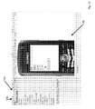
- a drop down list 116c in IDE 70c includes multiple different portable electronic device types.
- the content of the list is determined by the plugin, which provides rendering instructions to IDE 70c to allow a user-interface design window 118c to simulate the portable electronic device 120c that is selected from the list 116c.
- the selected portable electronic device is a Blackberry 8100 TM . As shown, a skin resembling this device appears in the design window 118c.
- buttons having thumbnail images of the different devices may alternatively be provided.
- Plugin 96c includes multiple sets of commands that control the appearance of the design window 118c for multiple portable electronic device types. Each set of commands controls appearance attributes for a particular device type.
- Device type attributes can include, but are not limited to: screen size, button location, button appearance, menu location, menu appearance, borders and background images, for example.
- a different portable electronic device is simulated in the application design window 118c of IDE 70c.
- the skin simulates a Pocket PC device.
- any number of different types of portable electronic devices may be included in the plugin program. Some examples include: Blackberry TM devices, PocketPC TM devices, Palm TM devices and Nokia TM devices.
- Figure 12 shows an application design window 118c as it would appear without a portable electronic device skin selected. As shown, the screen layout is quite different than the layout shown in Figures 10 and 11 . Without the device-specific simulated environment, the developer of the application cannot see how the application will appear on the portable electronic device until the application is actually downloaded to the device.
- the developer can make the appropriate adjustments to the developed user interface to best take advantage of the targeted platform's user-interface attributes. In addition, this can reduce the likelihood of re-design being required following device-specific testing.
- a method for building an application in an IDE is represented in the form of a flow-chart indicated generally at 1100.
- the user selects a portable electronic device type from a list of supported portable electronic devices.
- a user-interface design window 118b is launched in the IDE 70c.
- the design window 118c includes a skin of the selected device so that the appearance of the application design window 118c corresponds to the selected device type.
- the user builds an application in the design window 118c. Techniques for building applications are well known in the art and therefore will not be described further here.
- the user downloads the completed application onto the portable electronic device. Once downloaded, the user is able to view the application on the portable electronic device.
- the appearance of the application on the portable electronic device is generally identical to the appearance of the application on the simulated portable electronic device in the design window 118c of IDE 70c.
- the XML file includes a main attribute at the top called “fledgeLocation". This is the location of the default simulator that is launched for all of the skins provided in the XML file when the developed application is debugged in the IDE. "isRelativePath" in the XML file specifies if the path to the default simulator is relative to the IDE running directory. Alternatively, rather than having a single default simulator for all skins in the XML file, each skin may be provided with its own default simulator. In addition, command line parameters on each skin element may be specified for the simulator to be launched. These parameters are specific to the simulator being launched.
- the plugin program is replaced by code that is integrated into the IDE.
- Device-specific application design windows are therefore provided in the main IDE and no plugin is required.
- the XML file is replaced with a comma delimited file, an ini (initialization) file, a database file or windows registry.
Abstract
Description
- This patent application claims the benefit of
U.S. Provisional Application No. 60/916,404, filed May 7, 2007 - A portion of the disclosure of this patent document contains material which is subject to copyright protection. The copyright owner has no objection to the facsimile reproduction by any one of the patent document or patent disclosure, as it appears in the Patent and Trademark Office patent file or records, but otherwise reserves all copyright rights whatsoever.
- The present disclosure relates to apparatuses and methods for programming a computing device.
- Programming languages are increasing in complexity and functionality. The broad range of available computing devices, including desktop computers, laptop computers, personal digital assistants, cellular telephones, wireless email paging devices continuously spurs the need for even more sophisticated programming languages in order to utilize the functionality of those computing environments.
- An integrated development environment (IDE), also known as an integrated design environment and an integrated debugging environment, can be helpful for computer programmers who are developing software for different computing devices. IDEs can simplify the task of programmers so that they need not understand all of the peculiar details of every computing device for which they are tasked with programming. An example of a known IDE is JSEclipse from Adobe Systems Romania, formerly known as InterAKT Bdul. Vasile Milea, nr 2H, et 1, ZIP 061344, Bucharest, Romania, based on Eclipse from the Eclipse Foundation, Inc. 102 Centrepointe Drive, Ottawa, Ontario, Canada, K2G 6B1. Another example is Microsoft Visual Studio from Microsoft Corporation of 205 108th Ave. NE, Suite 400, Bellevue, WA 98004. There are challenges associated with these IDEs. Indeed, user interfaces allow users to interact with software applications. Different user interfaces display the same application differently based on the screen size and other attributes of the user interface. This presents a challenge when designing software applications, particularly for portable electronic devices.
- Screen size and shape varies significantly between portable electronic devices. In addition, devices often use particular user interface themes that impact the appearance of software applications. Screen controls such as buttons and dropdown lists, for example, are painted in a different manner depending on the device. As a result, there are challenges in designing a software application using a single screen layout. In some cases, software application designers perform multiple design iterations before the software application appears as intended on a targeted device. It is therefore desirable to improve the design process for portable electronic device software applications.
- In one aspect there is provided a plugin for a Rapid Application Development Tool including: a set of commands for defining an appearance of a UI design window in the Rapid Application Development Tool, the appearance of the application design window simulating a display screen of a portable electronic device and the set of commands being related to one type of portable electronic device.
- In another aspect there is provided a method for building an application in a Rapid Application Development tool, the method including: selecting a skin corresponding to a portable electronic device type; launching a UI design window in the Rapid Application Development Tool, an appearance of the application design window simulating a portable electronic device having the portable electronic device type; and building the application in the Rapid Application Development Tool.
-
Figure 1 shows a system for programming a computing device. -
Figure 2 is a graphic representation of the IDE fromFigure 1 . -
Figure 3 is a flowchart depicting a method for programming a computing device, according to an example embodiment. -
Figure 4 is a consolidation ofFigures 1 and2 . -
Figure 5 is a flowchart depicting a method of updating an IDE, according to an example embodiment. -
Figure 6 shows a modification of the system ofFigure 4 , modified using the method inFigure 5 . -
Figure 7 shows a system for programming a computing device in accordance with another example embodiment. -
Figure 8 shows an example performance of the system ofFigure 7 . -
Figure 9 is a schematic view of an IDE including a plugin according to an example embodiment; -
Figures 10 to 12 are screen shots of portions of a IDE environment; and -
Figure 13 is a flowchart depicting a method for building an application using the plugin ofFigure 9 , according to an example embodiment. - Referring now to
Figure 1 , a system for programming a computing device is indicated generally at 50.System 50 includes atower 54 coupled to adisplay 58, akeyboard 62 and acomputing device 66. An IDE 70 executes ontower 54. A developerD using display 58 andkeyboard 62 can interact with anIDE executing tower 54 in order to developsoftware 74 for execution ondevice 66, particularly for use whendevice 66 is disconnected fromtower 54. As will become more apparent from the discussion further below, the term "develop" is used in a non-limiting sense, to refer to any exercise related to the creation and/or modification and/or the like ofsoftware 74. -
Tower 54 houses at least one central processing unit, random access memory (or other volatile storage), read only memory and hard disc storage (or other non-volatile storage) all of which are interconnected by a bus. The computing environment oftower 54renders tower 54 operable to execute IDE 70. IDE 70 executes on the central processing unit oftower 54, making appropriate and/or necessary use of other components withintower 54, and receiving instructions from developer D viakeyboard 62 and generating responses for developer D ondisplay 58. - Other types of input peripherals, in addition to or in lieu of
keyboard 62 are contemplated. Likewise, other types of output peripherals, in addition to or in lieu ofdisplay 58 are contemplated. -
Computing device 66 is a portable wireless email telephony device, but it should be understood that in other exampleembodiments computing device 66 can be any type of computing environment for which developer D may be called upon to developsoftware 74 using IDE 70.Software 74 can be any software object or software application or the like that executes on thecomputing environment device 66. - It should be understood that, overall, the environment of
system 50, and the components therein, are examples and that other configurations are contemplated. - Referring now to
Figure 2 , IDE 70 is shown in greater detail. IDE 70 includes aprogramming language 80 within whichsource code 84 can be developed.Programming language 80 can be based on any known or future-contemplated programming language, including, by way of non-limiting example, C++, Java, BASIC. Of note, however, is thatprogramming language 80 is based on a programming language associated withdevice 66. Accordingly,programming language 80 is chosen to conform to the computing environment ofdevice 66. -
Source code 84, when based on a compiled language (e.g. C++), can be compiled to becomesoftware 74 forcomputing device 66.Source code 84, when based on an interpreted language (e.g. Java, JavaScript, VBScript) can be installed assoftware 74 oncomputing device 66, and then during run-time ondevice 66,software 74 will be interpreted according to a language interpreter oncomputing device 66. This step of compilation and/or installation is represented by the arrow indicated at 78 inFigure 2 . - IDE 70 also includes a
development assistant engine 88, which is configured to operate in conjunction with aneditor 92, in order to developsource code 84. Developer D can utilizekeyboard 62 and display 58 in order to manipulateeditor 92 to developsource code 84.Development assistant engine 88 is configured to provide a number of development assistant tools to developer D as developer D useseditor 92. Example tools include, but are not limited to code completion, automatic code correction, and context-sensitive help. -
Engine 88 itself includes anengine definition file 96 which defines the tools that are implemented byengine 88.Engine definition file 96 corresponds with the syntax and programming rules associated withlanguage 80, while the remainder ofengine 88 is not tied in any manner tolanguage 80. -
Engine definition file 96 is fully editable, and, in a present example embodiment,engine definition file 96 is based on the eXtended Markup Language ("XML"), butengine definition file 96 can also be simply a plain text file or based on any other type of markup language or the like.Engine definition file 96 can be a database file with entries that can be manipulated. In the present example embodiment, file 96 is an XML file used for ease of readability and manipulation.Engine definition file 96 can be implemented as a plurality of discrete sub-files rather than a single file. - An example
engine definition file 96 is provided in Table I.Table I Example Engine Definition File 96* Example Command* <Keyword>while</Keyword> * Example Context Sensitive Help * <CursorFocus="While" Comment= "Utilized for Do-While loop structure. Syntax is "While (Condition)". Correct syntax requires providing Condition which when true will cause looping, and when false will cause looping to cease." /> -
Engine definition file 96 working in conjunction withengine 88 implements the various development assistant tools. Those skilled in the art will recognize that Table I includes an example of at least a portion of anengine definition file 96 that includes content for a context-sensitive help tool wherein a text-bubble is provided adjacent to the text being entered by developer D. As per the example in Table I, assume thatlanguage 80 includes the command "While", thenengine 88 anddefinition file 96 can cooperate so that if the cursor ineditor 92 is focused on the command "While", thenengine 88 would display ineditor 92 a text-bubble that displays the comment "Utilized for Do-While loop structure. Syntax is 'While (Condition)'. Correct syntax requires providing Condition which when true will cause looping, and when false will cause looping to cease". The raw-data relationship that associates "While" with the previously-described example comment is maintained withindefinition file 96, while the logic to present this comment as a text bubble in association with "While" is embedded withinengine 88.Engine 88 is configured to readfile 96 to obtain the comment and its associated command, "While", and implement logic withinengine 88 to present the comment in association with the term "While" withineditor 92. Thus, the aspects of the contents of comment that are specific to commands withlanguage 80 are maintained within a separately editableengine definition file 96, without impactingengine 88. - Those skilled in the art will recognize that the code completion tool could include predictive text capabilities. For example, using the example
engine definition file 96 in Table I, it is assumed thatlanguage 80 includes the command "While". Thus, if developer D enters the text "Wh" intoeditor 92, thenengine 88, working in conjunction withdefinition file 96 could predict that developer D was entering the command "While" and complete typing the remainder of the command so that developer D need not type the remaining letters of "ile" viakeyboard 62.Engine 88 can examine file 96 and determine the presence of the "While" command and define a relationship that associates "Wh" with "While", -- thus the logic to complete "Wh" into "While" would be embedded withinengine 88.Engine 88 is configured to readfile 96 to obtain the keyword "While" and implement logic withinengine 88 to actually perform code completion withineditor 92. Thus, the command "While", which is specific tolanguage 80 is maintained within a separately editableengine definition file 96, without impacting the tool functionality inengine 88. - Those skilled in the art will recognize that an automatic code correction tool could include similar functionality to automatic spelling correction found in word processors. For example, again using the example
engine definition file 96 in Table I, it is assumed thatlanguage 80 includes the command "While", then if developer D enters the text "Whlie" intoeditor 92, thenengine 88 would assume that developer D intended to enter the command "While" and would automatically change "Whlie" into "While". Again, the definition oflanguage 80 can thus be maintained infile 96, without impactingengine 88. - All of the tools can also work in conjunction with each other. Another example tool is a method and tips tool that provides information about a current method that is being worked on. Further tools that can be included within
engine 88 will now occur to those skilled in the art. - Referring now to
Figure 3 , a method of programming a computing device is depicted in the form of a flowchart and indicated generally at 300.Method 300 can be used in conjunction withsystem 50, however, it should be understood thatmethod 300 can be used with other systems, other thansystem 50, and that bothmethod 300 andsystem 50 can be varied in accordance with the teachings herein. For example, the sequence of steps ofmethod 300 can be changed, and/or certain steps may be performed substantially in parallel. Also, the particular manner in which any given step is implemented is not particularly limited. - To assist in
further understanding system 50 and the understanding ofmethod 300,method 300 will be explained in relation to its performance onsystem 50. Beginning atstep 305, input is received at an editor. The input atstep 305 is typically programming instructions that are received byeditor 92, as those instructions are entered viakeyboard 62, and simultaneously displayed ondisplay 58 in accordance with the functionality ofeditor 92. - Next, at
step 310, the development assistant engine accesses the input received atstep 305. Insystem 50, the input that was received byeditor 92 is now accessed bydevelopment assistant engine 88. - At
step 315, the development engine accesses the engine definition file. Insystem 50,development assistant engine 88 will read the contents ofengine definition file 96. In a present example embodiment,development assistant engine 88 can loaddefinition file 96 into random access memory for speed of execution and traversal offile 96. - At
step 320, a determination is made as to whether any input received atstep 305 matches any of the conditions of the engine definition file. Step 320 in a present example embodiment is performed bydevelopment assistant engine 88, which makes a comparison between any conditions that have been defined inengine definition file 96 with the input that was accessed bydevelopment assistant engine 88 atstep 310. If a match is not found, thenmethod 300 returns fromstep 320 back to step 305. However, if a match is found, thenmethod 300 advances fromstep 320 to step 325, at which point a development assistant tool corresponding to the condition matched atstep 320 is provided viaeditor 92 ondisplay 58 to developer D. - Those skilled in the art will now recognize that the performance of
step 325 can correspond with the above-described examples given in relation to the exampleengine definition file 96 Table I. For example, assuming that the input received atstep 305 was "Wh", then the code completion tool can be provided atstep 325 to automatically type the complete command "While" withineditor 92 and thereby obviate the need for developer D to finish typing the "ile". - Note that, at this point,
method 300 can cycle back fromstep 325 to step 305, and now detect the input "While" atstep 305, such that during this cycle throughmethod 300, atstep 325 the context sensitive help tool can be provided atstep 325 and thereby provide a text-bubble which displays the comment "Utilized for Do-While loop structure. Syntax is "While (Condition)". Correct syntax requires providing Condition which when true will cause looping, and when false will cause looping to cease." - Another example embodiment represents a method for modifying an IDE to correspond with a different or new computing device. This example embodiment will now be explained with reference to
Figures 4-6 .Figure 4 combinesFigures 1 and2 to showsystem 50 all within a single Figure. Of note inFigure 4 ,language 80 corresponds to a computer programming language native tocomputing device 66, and likewiseengine definition file 96 corresponds tolanguage 80. However,editor 92,engine 88 independent fromlanguage 80 and/ordevice 66.Figure 5 -
Figure 5 shows a flowchart depicting a method for modifying an IDE to correspond with a different or new computing device that has a new language associated therewith. -
Figure 6 showssystem 50a, which is substantially the same assystem 50 and identical elements have identical references, except followed by a suffix a. However, elements insystem 50a that are modified from their corresponding elements insystem 50 also include the suffix M. Thus, inFigure 6 , device 66aM is a different device thandevice 66. Likewise, language 80aM corresponds to device 66aM, and is also different from language 80a. Likewise, language definition file 96aM corresponds with language 80aM, and is different thandefinition file 96. - Referring again to
Figure 5, Figure 5 shows a method wherebylanguage definition file 96 can be modified so thatIDE 70 can be used to develop software for a modified computing device 66aM instead of theoriginal computing device 66. Atstep 505, an existing engine definition file is received. Thus, in the example shown inFigure 4 ,language definition file 96 is loaded into an editor.Editor 92 can be used to edit file 96 (though relying solely on the editing features ofeditor 92 and without reliance on the features of engine 88), however this is a non-limiting example and any editor can also be used due to the structure offile 96. Atstep 510,language definition file 96 is edited.File 96 is edited to conform to language 80aM in order to create language definition file 96aM. Atstep 515, language definition file 96aM is saved withinengine 88a, as depicted inFigure 6 . - An example engine definition file 96aM is provided in Table II
Table II Example modified Engine Definition File 96aM *Example Command* <Keyword>while</Keyword> <Keyword>until</Keyword> * Example Context Sensitive Help * <CursorFocus="While" Comment= "Utilized for Do-While loop structure. Syntax is "While (Condition)". Correct syntax requires providing Condition which when true will cause looping, and when false will cause looping to cease." /> <CursorFocus="Until" Comment= "Utilized for Do-Until loop structure. Syntax is 'Until (Condition)'. Correct syntax requires providing Condition which when true will cause looping, and when false will cause looping to cease." /> - A comparison of Table II and Table I shows that Table II is substantially the same as Table I, except that new text identifying a new keyword has been added, namely, the keyword "until". Additional context sensitive help has been added, namely, that if the text "Until" is detected then the following comment will be displayed: "Utilized for Do-Until loop structure. Syntax is "'Until (Condition)"'. Correct syntax requires providing Condition which when true will cause looping, and when false will cause looping to cease.
- Thus, once
method 500 has been performed, developer D can immediately begin developing software for device 66aM, based on developer D's existing understanding ofdevice 66, and without having to take any particular steps to learn about the functionality of device 66aM. - Thus, as manufacturers of devices such as 66 enhance, change or create new devices, those same manufacturers can simply provide a copy of
language 80 that corresponds to the device, and likewise provide a copy ofengine definition file 96 in text format, without having to provide a completely new IDE as well.Language 80 andengine definition file 96 are modular, and can be changed, without disrupting or requiring changes to, or recompilation of the IDE itself, or any of the other components therein. The foregoing can be useful whendevice 66 already relies on the essential substance of a well-known programming language that is already known to developer D, but includes various extensions to that programming language that are unique to the functionality ofdevice 66 and yet which are unknown to developer D. Likewise, developer D can continue to use the same IDE environment with which the developer D is already familiar for anynew devices 66 with which that developer D is not already familiar. - It should also be understood that
method 500 can be modified to simply create a new definition file for any new programming languages that may be developed. - The foregoing provides certain example embodiments, but it should be understood that variations, subsets, and combinations of those example embodiments are contemplated. For example, it should be understood that the Engine Definition Files in Table I and Table II are greatly simplified in order to assist in explaining the teachings herein. Appendix I attached hereto shows a more detailed, yet still example,
engine definition file 96 in the form of two files, MDScript.xml and Library.xml, which collectively can includeengine definition file 96. Appendix II, attached hereto, shows a detailed example of text that can be added toengine definition file 96, such that collectively Appendix I and Appendix II can represent engine definition file 96aM. - The teachings herein can also be incorporated with one or more of the teachings of
WO-2004-59938 WO-2004-59957 WO-2004-59939 U.S. Application Serial No. 11/078,331 , the contents of each of which are incorporated herein by reference. Indeed,Figure 7 showssystem 50b, which is substantially the same assystem 50 and identical elements have identical references, except followed by a suffix b. However, certain new elements appear insystem 50b and those elements reflect aspects of howsystem 50 can be modified to operate with the teachings ofWO-2004-59938 WO-2004-59957 WO-2004-59939 U.S. Application Serial No. 11/078,331 . - More specifically,
system 50b also includes adata repository 100b onto whichsoftware 74b can be stored for eventual execution ondevice 66b using aruntime environment 104b ondevice 66b. Indeed,system 50b is configured forsoftware 74b wheresoftware 74b is based on an interpretedlanguage 80b, such as JavaScript or the like. Thus,runtime environment 104b is an application ondevice 66b that corresponds tolanguage 80b -- which is of course thesame language 80b that is used byIDE 70b used to createsoftware 74b.Runtime environment 104b also, of course, corresponds toprogramming language 80b. -
System 50b thus also includes anapplication gateway 108b that is connected torepository 100b. In turn,application gateway 108b is connected to awireless base station 104b, which permitsdevice 66b to communicate withapplication gateway 108b viawireless link 112b. (Other infrastructures, however, thatpermit device 66b to communicate withapplication gateway 108b are contemplated).Application gateway 108b is also connected to a wide area network, which in the present example embodiment is theInternet 116b.Internet 116b, in turn, is connected to anapplication server 120b.Application server 120b can host any type ofservice 124b, such as a webpage, am application, or any other type of service that a user ofdevice 66b may wish to access usingsoftware 74b viaInternet 116b. - Example operation of
system 50b is shown inFigure 8 , wherein a request fromdevice 66 toapplication server 120b is represented as a dotted line which is indicated atreference 128b.Request 128b includes a request forservice 124b.Application server 120b is configured to correlate information aboutdevice 66b, including the fact thatlanguage 80b is specific todevice 66b, and to provide a response to request 128b by providingsoftware 74b toruntime environment 104b withindevice 66, such response being represented as a dotted line which is indicated atreference 132b. Whileresponse 132b can result in the entirety ofsoftware 74b being "downloaded" todevice 66b, it should be understood that it is contemplated that scripts (i.e. portions) ofsoftware 74b are provided todevice 66b as needed and thatruntime environment 104b executes those scripts, and thusresponse 132b can in fact represent a plurality of responses. Once relevant scripts ofsoftware 74b are executing indevice 66b, thenapplication gateway 108b also provides a second response by providingservice 124b tosoftware 74b assoftware 74b is executing withindevice 66b and calling uponservice 124b. The second response (which in fact may be a plurality of responses) is represented as a dotted line which is indicated atreference 136b. - It is to be reiterated that
software 74b andservice 124b can be virtually unlimited in scope and thus thatsystem 50b represents a generic architecture. A specific example can assist, however, in understanding the full potential scope ofsystem 50b.Service 124b can include mapping information, whilesoftware 74b can be mapping software. Thus, should a user ofdevice 66b wish to view the mapping information associated withservice 124b, then themapping software 74b needed to view the maps can be executed inruntime environment 104b and thenservice 124b can be accessed. One advantage of this example embodiment is that developer D can create different mapping software respective to different devices, and yet each of those devices can access thesame service 124b, without modifyingservice 124b and/or having to cause 124b to be specifically tailored to each device that accesses it. Thus, as new devices are deployed, developer D can simply make software to those devices available inrepository 100b, and no modifications toservice 124b are required. - Referring now to
Figure 9 , an IDE in accordance with another example embodiment is indicated generally at 70c.IDE 70c can be incorporated into the same basic framework ofsystem 50 as described above, but subject to the modifications discussed below. Like components in the following description bear like-references to substantially corresponding in relation tosystem 50 andsystem 50a as described above. However, certain modifications are effected toIDE 70c. Of note is thatengine definition file 96 is not included inIDE 70c, and instead aplugin program 96c is used withIDE 70c. The relationship between aplugin program 96c according to another example embodiment and aIDE 70c is generally shown inFigure 9 . Likeengine definition file 96,plugin program 96c is, in a present example embodiment, an XML (Extensible MarkUp Language) file that is used in conjunction with theIDE 70c to allow for the selection of portable electronic device-specific skins in theIDE 70c. The application design window ofIDE 70c, which in the present example embodiment, is used for user interface (UI) design, is rendered based on the XML file. It should now be understood thatplugin program 96c is analogous toengine definition file 96, and thatplugin program 96c can be based on other editable file structures, other than XML, in the same manner thatengine definition file 96 can also be based on other editable file structures. - Of note, while
engine definition file 96 is operated in conjunction withengine 88 to provide code development tools,plugin program 96c provides device-specific skins within theIDE 70c. - An example of an XML file suitable for
plugin 96c is provided in Appendix III. The XML file is configurable to include skins for any number of portable electronic devices. The XML file defines screen size, default colors, button styles and other device-specific attributes. - Referring to
Figure 10 , a drop downlist 116c inIDE 70c includes multiple different portable electronic device types. The content of the list is determined by the plugin, which provides rendering instructions toIDE 70c to allow a user-interface design window 118c to simulate the portableelectronic device 120c that is selected from thelist 116c. In the example ofFigure 10 , the selected portable electronic device is a Blackberry 8100™. As shown, a skin resembling this device appears in thedesign window 118c. - It will be appreciated by a person skilled in the art that selection of the portable electronic device type is not limited to the drop down list. For example, buttons having thumbnail images of the different devices may alternatively be provided.
-
Plugin 96c includes multiple sets of commands that control the appearance of thedesign window 118c for multiple portable electronic device types. Each set of commands controls appearance attributes for a particular device type. Device type attributes can include, but are not limited to: screen size, button location, button appearance, menu location, menu appearance, borders and background images, for example. By providing a simulation of a portable electronic device type in thedesign window 118c, a developer can design an application while taking into account the appearance attributes of a specific type of portable electronic device. Therefore, when the application has been completed, the appearance of the application in the IDE will match the appearance of the application when viewed on the actual device. - Referring to
Figure 11 , a different portable electronic device is simulated in theapplication design window 118c ofIDE 70c. In this example, the skin simulates a Pocket PC device. It will be appreciated that any number of different types of portable electronic devices may be included in the plugin program. Some examples include: Blackberry™ devices, PocketPC™ devices, Palm™ devices and Nokia™ devices. -
Figure 12 shows anapplication design window 118c as it would appear without a portable electronic device skin selected. As shown, the screen layout is quite different than the layout shown inFigures 10 and11 . Without the device-specific simulated environment, the developer of the application cannot see how the application will appear on the portable electronic device until the application is actually downloaded to the device. - By showing the developer how their developed application will look on a targeted portable electronic device, the developer can make the appropriate adjustments to the developed user interface to best take advantage of the targeted platform's user-interface attributes. In addition, this can reduce the likelihood of re-design being required following device-specific testing.
- Referring to
Figure 13 , a method for building an application in an IDE is represented in the form of a flow-chart indicated generally at 1100. At step 1122, the user selects a portable electronic device type from a list of supported portable electronic devices. At step 1124, a user-interface design window 118b is launched in theIDE 70c. Thedesign window 118c includes a skin of the selected device so that the appearance of theapplication design window 118c corresponds to the selected device type. At step 1126, the user builds an application in thedesign window 118c. Techniques for building applications are well known in the art and therefore will not be described further here. At step 1128, the user downloads the completed application onto the portable electronic device. Once downloaded, the user is able to view the application on the portable electronic device. The appearance of the application on the portable electronic device is generally identical to the appearance of the application on the simulated portable electronic device in thedesign window 118c ofIDE 70c. - In another example embodiment, the XML file includes a main attribute at the top called "fledgeLocation". This is the location of the default simulator that is launched for all of the skins provided in the XML file when the developed application is debugged in the IDE. "isRelativePath" in the XML file specifies if the path to the default simulator is relative to the IDE running directory. Alternatively, rather than having a single default simulator for all skins in the XML file, each skin may be provided with its own default simulator. In addition, command line parameters on each skin element may be specified for the simulator to be launched. These parameters are specific to the simulator being launched.
- In another example embodiment, the plugin program is replaced by code that is integrated into the IDE. Device-specific application design windows are therefore provided in the main IDE and no plugin is required.
- In still another example embodiment, the XML file is replaced with a comma delimited file, an ini (initialization) file, a database file or windows registry.
- Various specific example embodiments have been shown and described herein. However, modifications and variations may occur to those skilled in the art. All such modifications and variations are believed to be within the sphere and scope of the present specification.
- It is to be understood that combinations, variations, and/or subsets of the various example embodiments described herein are contemplated.


Claims (21)
- An apparatus for programming a computing device comprising:at least one central processing unit, a volatile storage unit and non-volatile storage unit interconnected by a bus;an input peripheral for receiving input from a user and connected to the at least one central processing unit;an output peripheral for generating output for presentation to a user andconnected to the at least one central processing unit;the at least one processing unit configured to execute a plurality of programming instructions implementing an integrated design environment; the at least one processing unit further configured to execute a set of commands in conjunction with the integrated design environment "IDE" for defining an appearance of a user-interface design window on the output peripheral, the appearance of the application design window simulating a display screen of a portable electronic device and the set of commands being related to one type of portable electronic device.
- The apparatus of claim 1 wherein the set of commands includes multiple sets of commands, each of the sets of commands being related to a different type of portable electronic device.
- The apparatus of claim 1 or claim 2 wherein the set of commands controls parameters selected from the group consisting of: screen size, button location and button appearance.
- The apparatus of any one of claims 1-3 wherein the set of commands specifies a default simulator for a skin defined by the set of commands.
- The apparatus of any one of claims 1-4 wherein the set of commands is implemented as an editable file that is separate from the IDE.
- The apparatus of any one of claims 1-5 wherein the set of commands is based on the eXtended Markup Language. ("XML")
- A method of developing software for a computing device comprising:selecting a skin corresponding to a portable electronic device type;launching a user-interface design window in an Integrated DevelopmentEnvironment, an appearance of an application design window within the Integrated Development Environment simulating a portable electronic device having the portable electronic device type; andbuilding the application in the Integrated Development Environment.
- A method as claimed in claim 7, wherein the skin is selectable from a list, the list including multiple portable electronic device types.
- A method as claimed in claim 7 or claim 8, wherein the skin is provided by a plugin that interacts with the Integrated Development Environment tool.
- A method as claimed in claim 9, wherein the plugin is an XML (Extensible MarkUp Language) file.
- A method as claimed in claim 9, wherein the plugin specifies a default simulator for the skin.
- A method as claimed any one of claims 7-11, wherein a set of commands in the Integrated Development Environment are executable in conjunction with the definition file as part of the building.
- A method as claimed in claim 12 wherein the commands control parameters selected from the group consisting of: screen size, button location and button appearance
- A method of modifying an integrated development engine (IDE) for programming a computing device comprising:receiving a definition file corresponding to a first skin associated with a first portable electronic device type;editing the definition file so that the definition file corresponds to a second skin associated with a second portable electronic device type;saving the edited definition file for subsequent use by the IDE.
- A method as claimed in claim 14, wherein the first skin and the second skin are selectable from a list, the list including the first portable electronic device type and the second portable electronic device type.
- A method as claimed in claim 14 or claim 15, wherein the definition file is provided by a plugin that interacts with the Integrated Development Environment tool.
- A method as claimed in claim 16, wherein the plugin is an XML (Extensible MarkUp Language) file.
- A method as claimed in claim 16, wherein the plugin specifies a default simulator corresponding to a type of portable electronic device.
- A method as claimed in any one of claims 14-18, wherein a set of commands in the IDE are executable in conjunction with the definition file.
- A method as claimed in claim 19 wherein the commands control parameters selected from the group consisting of: screen size, button location and button appearance.
- Computer readable media comprising instructions that, when executed by a processor of a computing system adapt the system to perform all of the steps of any of claims 7 to 20.
Applications Claiming Priority (1)
| Application Number | Priority Date | Filing Date | Title |
|---|---|---|---|
| US91640407P | 2007-05-07 | 2007-05-07 |
Publications (1)
| Publication Number | Publication Date |
|---|---|
| EP1990716A1 true EP1990716A1 (en) | 2008-11-12 |
Family
ID=39673454
Family Applications (1)
| Application Number | Title | Priority Date | Filing Date |
|---|---|---|---|
| EP08155835A Ceased EP1990716A1 (en) | 2007-05-07 | 2008-05-07 | System and method for device skinning |
Country Status (3)
| Country | Link |
|---|---|
| US (1) | US8887075B2 (en) |
| EP (1) | EP1990716A1 (en) |
| CA (1) | CA2630868A1 (en) |
Families Citing this family (1)
| Publication number | Priority date | Publication date | Assignee | Title |
|---|---|---|---|---|
| EP2270658A1 (en) * | 2009-06-22 | 2011-01-05 | Clayster Asia Ltd. | Method and computer system for introducing client devices into a client-server network |
Family Cites Families (7)
| Publication number | Priority date | Publication date | Assignee | Title |
|---|---|---|---|---|
| US6314559B1 (en) * | 1997-10-02 | 2001-11-06 | Barland Software Corporation | Development system with methods for assisting a user with inputting source code |
| US6305008B1 (en) | 1998-11-13 | 2001-10-16 | Microsoft Corporation | Automatic statement completion |
| US7174534B2 (en) * | 2001-01-22 | 2007-02-06 | Symbol Technologies, Inc. | Efficient system and method for running and analyzing multi-channel, multi-modal applications |
| US20060090154A1 (en) | 2004-10-07 | 2006-04-27 | International Business Machines Corp. | System and method for contributing remote object content to an integrated development environment type-ahead |
| US7478367B2 (en) * | 2005-01-11 | 2009-01-13 | International Business Machines Corporation | Dynamic source code analyzer |
| EP2126713A2 (en) * | 2007-02-19 | 2009-12-02 | Ondeego, Inc. | Methods and system to create applications and distribute applications to a remote device |
| WO2008106643A2 (en) | 2007-03-01 | 2008-09-04 | Formotus, Inc. | Forms conversion and deployment system for mobile devices |
-
2008
- 2008-05-07 EP EP08155835A patent/EP1990716A1/en not_active Ceased
- 2008-05-07 CA CA002630868A patent/CA2630868A1/en not_active Abandoned
- 2008-05-07 US US12/116,419 patent/US8887075B2/en not_active Expired - Fee Related
Non-Patent Citations (4)
| Title |
|---|
| LANDERS ET AL: "Technical Working Paper 2002, Ericsson Education (From e-Learning to m-Learning)", 2002, pages 1 - 33, XP002492048, Retrieved from the Internet <URL:http://learning.ericsson.net/mlearning2/project_one/technical_working_paper_ericsson.pdf> [retrieved on 20080812] * |
| QUSAY H MAHMOUD: "WAP for Java developers", JAVAWORLD, 2 June 2000 (2000-06-02), pages 1 - 7, XP002492046 |
| QUSAY H MAHMOUD: "WAP for Java developers", JAVAWORLD, 2 June 2000 (2000-06-02), pages 1 - 7, XP002492046, Retrieved from the Internet <URL:http://www.javaworld.com/javaworld/jw-06-2000/jw-0602-wap.html> [retrieved on 20060812] * |
| W3C: "Content Selection for Device Independence (DISelect) 1.0 - W3C Working Draft 10 October 2006", 10 October 2006 (2006-10-10), pages 1 - 16, XP002492047, Retrieved from the Internet <URL:http://www.w3.org/TR/2006/WD-cselection-20061010/> [retrieved on 20080812] * |
Also Published As
| Publication number | Publication date |
|---|---|
| US8887075B2 (en) | 2014-11-11 |
| CA2630868A1 (en) | 2008-11-07 |
| US20080282227A1 (en) | 2008-11-13 |
Similar Documents
| Publication | Publication Date | Title |
|---|---|---|
| US10656920B2 (en) | Dynamically adaptable tool for graphical development of user interfaces | |
| US8201143B2 (en) | Dynamic mating of a modified user interface with pre-modified user interface code library | |
| US7886284B2 (en) | Using a backend simulator to test and develop xforms templates before linking the xforms templates to backend data processing systems | |
| US7757207B2 (en) | Form skin and design time WYSIWYG for .net compact framework | |
| JP5021211B2 (en) | Method and system for digital device menu editor | |
| US6282699B1 (en) | Code node for a graphical programming system which invokes execution of textual code | |
| JP2795244B2 (en) | Program debugging system | |
| US7761859B2 (en) | Application development environment with features for aiding a user in writing function calls | |
| US7689979B1 (en) | Methods and apparatus to improve application launch time | |
| KR20010006997A (en) | System and method for improving the manageability and usability of a java environment | |
| CN102667730A (en) | Design time debugging | |
| US8930879B2 (en) | Application building | |
| KR20070053106A (en) | Pseudo translation within integrated development environment | |
| US8745602B2 (en) | Automatic configuration of project system from project capabilities | |
| EP1990715A1 (en) | System, apparatus and method for programming a computing device | |
| JP2008276690A (en) | Development system, server for development system, and development method | |
| US20060036997A1 (en) | Application development environment with features for increasing the ease and efficiency of viewing function help text | |
| US20080127061A1 (en) | Method and system for editing code | |
| US8887075B2 (en) | System and method for device skinning | |
| Cornez | Android Programming Concepts | |
| WO2004088508A2 (en) | A method of creating software that is portable across different operating systems | |
| CN115113850A (en) | Cross-platform application construction and operation method, server, terminal and system | |
| Feng et al. | Action-driven automation test framework for graphical user interface (GUI) software testing | |
| Guo et al. | Research on Key Techniques for Enginery Teaching Platform Based on Computer Dynamic Simulation Technique. | |
| Kostaras et al. | What Is Apache NetBeans |
Legal Events
| Date | Code | Title | Description |
|---|---|---|---|
| PUAI | Public reference made under article 153(3) epc to a published international application that has entered the european phase |
Free format text: ORIGINAL CODE: 0009012 |
|
| 17P | Request for examination filed |
Effective date: 20080507 |
|
| AK | Designated contracting states |
Kind code of ref document: A1 Designated state(s): AT BE BG CH CY CZ DE DK EE ES FI FR GB GR HR HU IE IS IT LI LT LU LV MC MT NL NO PL PT RO SE SI SK TR |
|
| AX | Request for extension of the european patent |
Extension state: AL BA MK RS |
|
| AKX | Designation fees paid |
Designated state(s): AT BE BG CH CY CZ DE DK EE ES FI FR GB GR HR HU IE IS IT LI LT LU LV MC MT NL NO PL PT RO SE SI SK TR |
|
| AXX | Extension fees paid |
Extension state: RS Payment date: 20080507 Extension state: MK Payment date: 20080507 Extension state: BA Payment date: 20080507 Extension state: AL Payment date: 20080507 |
|
| 17Q | First examination report despatched |
Effective date: 20090709 |
|
| RAP1 | Party data changed (applicant data changed or rights of an application transferred) |
Owner name: RESEARCH IN MOTION LIMITED |
|
| STAA | Information on the status of an ep patent application or granted ep patent |
Free format text: STATUS: THE APPLICATION HAS BEEN REFUSED |
|
| 18R | Application refused |
Effective date: 20120321 |