EP1990304B1 - Bearing for a rope roll - Google Patents
Bearing for a rope roll Download PDFInfo
- Publication number
- EP1990304B1 EP1990304B1 EP08006950.3A EP08006950A EP1990304B1 EP 1990304 B1 EP1990304 B1 EP 1990304B1 EP 08006950 A EP08006950 A EP 08006950A EP 1990304 B1 EP1990304 B1 EP 1990304B1
- Authority
- EP
- European Patent Office
- Prior art keywords
- housing
- axis
- pulley
- bearing according
- rope roll
- Prior art date
- Legal status (The legal status is an assumption and is not a legal conclusion. Google has not performed a legal analysis and makes no representation as to the accuracy of the status listed.)
- Active
Links
Images
Classifications
-
- B—PERFORMING OPERATIONS; TRANSPORTING
- B65—CONVEYING; PACKING; STORING; HANDLING THIN OR FILAMENTARY MATERIAL
- B65H—HANDLING THIN OR FILAMENTARY MATERIAL, e.g. SHEETS, WEBS, CABLES
- B65H75/00—Storing webs, tapes, or filamentary material, e.g. on reels
- B65H75/02—Cores, formers, supports, or holders for coiled, wound, or folded material, e.g. reels, spindles, bobbins, cop tubes, cans, mandrels or chucks
- B65H75/34—Cores, formers, supports, or holders for coiled, wound, or folded material, e.g. reels, spindles, bobbins, cop tubes, cans, mandrels or chucks specially adapted or mounted for storing and repeatedly paying-out and re-storing lengths of material provided for particular purposes, e.g. anchored hoses, power cables
- B65H75/38—Cores, formers, supports, or holders for coiled, wound, or folded material, e.g. reels, spindles, bobbins, cop tubes, cans, mandrels or chucks specially adapted or mounted for storing and repeatedly paying-out and re-storing lengths of material provided for particular purposes, e.g. anchored hoses, power cables involving the use of a core or former internal to, and supporting, a stored package of material
- B65H75/40—Cores, formers, supports, or holders for coiled, wound, or folded material, e.g. reels, spindles, bobbins, cop tubes, cans, mandrels or chucks specially adapted or mounted for storing and repeatedly paying-out and re-storing lengths of material provided for particular purposes, e.g. anchored hoses, power cables involving the use of a core or former internal to, and supporting, a stored package of material mobile or transportable
- B65H75/406—Cores, formers, supports, or holders for coiled, wound, or folded material, e.g. reels, spindles, bobbins, cop tubes, cans, mandrels or chucks specially adapted or mounted for storing and repeatedly paying-out and re-storing lengths of material provided for particular purposes, e.g. anchored hoses, power cables involving the use of a core or former internal to, and supporting, a stored package of material mobile or transportable hand-held during use
-
- A—HUMAN NECESSITIES
- A01—AGRICULTURE; FORESTRY; ANIMAL HUSBANDRY; HUNTING; TRAPPING; FISHING
- A01K—ANIMAL HUSBANDRY; CARE OF BIRDS, FISHES, INSECTS; FISHING; REARING OR BREEDING ANIMALS, NOT OTHERWISE PROVIDED FOR; NEW BREEDS OF ANIMALS
- A01K27/00—Leads or collars, e.g. for dogs
- A01K27/003—Leads, leashes
- A01K27/004—Retractable leashes
-
- B—PERFORMING OPERATIONS; TRANSPORTING
- B65—CONVEYING; PACKING; STORING; HANDLING THIN OR FILAMENTARY MATERIAL
- B65H—HANDLING THIN OR FILAMENTARY MATERIAL, e.g. SHEETS, WEBS, CABLES
- B65H75/00—Storing webs, tapes, or filamentary material, e.g. on reels
- B65H75/02—Cores, formers, supports, or holders for coiled, wound, or folded material, e.g. reels, spindles, bobbins, cop tubes, cans, mandrels or chucks
- B65H75/34—Cores, formers, supports, or holders for coiled, wound, or folded material, e.g. reels, spindles, bobbins, cop tubes, cans, mandrels or chucks specially adapted or mounted for storing and repeatedly paying-out and re-storing lengths of material provided for particular purposes, e.g. anchored hoses, power cables
- B65H75/38—Cores, formers, supports, or holders for coiled, wound, or folded material, e.g. reels, spindles, bobbins, cop tubes, cans, mandrels or chucks specially adapted or mounted for storing and repeatedly paying-out and re-storing lengths of material provided for particular purposes, e.g. anchored hoses, power cables involving the use of a core or former internal to, and supporting, a stored package of material
- B65H75/44—Constructional details
-
- B—PERFORMING OPERATIONS; TRANSPORTING
- B65—CONVEYING; PACKING; STORING; HANDLING THIN OR FILAMENTARY MATERIAL
- B65H—HANDLING THIN OR FILAMENTARY MATERIAL, e.g. SHEETS, WEBS, CABLES
- B65H2701/00—Handled material; Storage means
- B65H2701/50—Storage means for webs, tapes, or filamentary material
- B65H2701/51—Cores or reels characterised by the material
- B65H2701/512—Cores or reels characterised by the material moulded
- B65H2701/5122—Plastics
Definitions
- the invention relates to a storage for a pulley which is rotatably mounted on an axle in a housing.
- the invention relates to a storage for a pulley a mechanically up and unwindable line for guiding animals.
- Such a leash is for example from the EP 0 941 657 B1 or from the US 4,390,142 known.
- the leash has a two-part housing in which a pulley is rotatably mounted on an axle.
- the line can be unwound against the force of a spring from the pulley and pulled out of the housing. Because of the tensioned spring, the leash automatically rewinds on the pulley.
- the leash may be designed as a cross-section approximately round rope or as a flat belt. It is in the following predominantly of a rope the speech, without this being a limitation connected.
- the arrangement is such that a housing part has the axis on which the pulley is rotatably arranged. After inserting the pulley on the axle, the other housing part is placed on the first housing part and connected thereto. It is formed a closed housing with an outlet for the leash. The pulley is guided axially between the two housing parts.
- the invention has for its object to form a storage of the type described so that a perfect run even when swollen by moisture pulley is possible.
- the object is achieved by a pulley according to claim 1.
- This ensures that, with the same coefficient of expansion of the pulley despite the expansion occurring in the axial direction, the absolute extent remains low. In fact, only the projection engaging the gap expands relative to the housing material. The absolute axial extent of expansion therefore remains low. As a result, the axial clearance during assembly with a dry pulley can be kept low, without the risk that when humid Pulley a clamping between the housing parts occurs.
- the projection may be formed as a single or a plurality of radially dipping noses in the gap.
- the projection is formed circumferentially.
- the projection may be formed as a radially inwardly facing extension of a lateral flange of the pulley. Such a projection can be easily produced during the production of the pulley.
- the gap is in the area of the axis. It can be provided that the circumferential gap is formed by an axial distance between a shoulder of the axle and a housing part. This facilitates the assembly of the line because the axis has no undercut through the gap. Rather, the gap between the shoulder of the axle and the attached housing part is formed.
- the housing has an upper housing part and a lower housing part, wherein the axis is connected to the one housing part and engages in the mounted position in the other housing part and has a shoulder, the radial end face of an axial distance to the other housing part to form having the circumferential gap.
- the pulley can be easily used because the inward projection rests on the shoulder and the thinner end of the axle passes through the remaining opening of the pulley to engage in the other housing part.
- the axial dimension of the axial distance between the shoulder and housing part is slightly larger than the axial width plus the axial extent of the projection of the pulley. Then a perfect running of the pulley is guaranteed even when wet.
- the maximum extent is material-dependent and can be determined.
- the pulley on the one hand and the housing on the other hand is basically arbitrary.
- the problem occurs in particular when the pulley and the housing parts have different coefficients of expansion.
- the pulley may be made of polyamide.
- the housing may be made of a different plastic.
- the axis is part of the lower housing part and dips with its free end into a receptacle of the housing upper part.
- the lower housing part can thus be produced by injection molding.
- the axle with a predetermined length dips into the receptacle and limits the axial distance.
- the length of the axis or the depth of the receptacle can be dimensioned such that the free end face of the axis abuts against the axial boundary of the receptacle in the axial direction.
- the gap is thus formed between the paragraph and this facing inner boundary of the housing part.
- the immersion depth of the axis in the receptacle is further limited, and it can be made a gap with a defined axial width in a simple and reproducible manner.
- the functional elements are included Made with the preparation, and rework is not required. The gap thus always has the desired axial dimension.
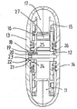
- FIGURE shows a cross section through a line casing with a pulley rotatably mounted therein.
- the leash shown in the drawing can be designed as an up and unwindable line for guiding animals.
- a pulley 11 which is rotatably mounted on an axle 12.
- the axis is part of a housing part 14, which with an opposite other housing part 13, a closed housing for the
- Pulley 11 forms.
- the axis may also be formed as a separate component and be connected, for example, with a housing part.
- the rope pulley has two spaced-apart side flanges 15, 16 which form between them a space 17 for the line to be wound up.
- the pulley 11 can be unrolled against the force of a spring not shown in detail 27 and rewound due to the spring force.
- the spring is usually designed as a spiral spring.
- the pulley 11 is usually made of polyamide, while the housing parts 13, 14 are made of a different plastic.
- the leash shown corresponds to a known leash for guiding animals and needs no further explanation.
- the pulley 11 is guided radially on the axis 12.
- the arrangement is such that the pulley engages the hub on the stationary axle 12 at at least two axially spaced locations 25, 26 supported.
- the pulley has a projection 18 pointing inwards on the axis, which runs in a circumferential gap 19.
- the arrangement is such that the gap between a shoulder 20 of the axle 12 and a housing part 13 is formed.
- the axis 12 extends into a concentric opening 22 of the housing part 13.
- the housing parts 13, 14 are axially connected to each other.
- the inner annular peripheral surface of the projection 18 is supported radially on the axis 12 and thus forms the one radial bearing 25 for the pulley 11.
- the opposite other radial bearing 26 is formed by the lateral flange 15, the inner annular surface is also supported on the axis 12.
- the immersion depth of the axis is limited by these projections, so that the gap receives a defined axial dimension. It can also be provided that the depth of the opening 22 and the length of the free end of the axle are chosen so that the end face of the axle abuts against the bottom of the opening. Even then, a defined axial dimension of the gap can be achieved.
- the pulley is supported in the radial direction on the thicker portion of the axle. In the axial direction, the pulley is supported in the assembled and shown in the drawing position with the projection 18 within the gap 19 from.
- the projection may be formed circumferentially and supported with its inner peripheral surface on the thinner portion of the axis. As a result, a radial bearing of the pulley is effected on the axis.
- the assembly of the line is done by the pulley 11 is first placed on the axis 12 of the housing base 14. Then the inner surface of the projection 18 rests on the shoulder 20 of the axle. Any existing spring mechanisms are then already mounted, and the rope is located on the pulley or is anchored there. Subsequently, the upper housing part 13 is placed. The leash is led out of an opening in the housing. The free end of the axle snaps into the opening 22 during assembly. There may be screws or other locking elements to securely connect the housing parts 13, 14.
- the gap between the shoulder 20 of the axle 12 and the housing part 13 is formed.
- the gap and the projection can be made very precisely by simple means, so that the projection in the gap can be kept with little play. A safe and quiet running of the pulley in the housing is achieved.
Description
Die Erfindung betrifft eine Lagerung für eine Seilrolle, die auf einer Achse in einem Gehäuse drehbar angeordnet ist. Insbesondere betrifft die Erfindung eine Lagerung für eine Seilrolle einer mechanisch auf- und abwickelbaren Leine zum Führen von Tieren.The invention relates to a storage for a pulley which is rotatably mounted on an axle in a housing. In particular, the invention relates to a storage for a pulley a mechanically up and unwindable line for guiding animals.
Eine solche Leine ist beispielsweise aus der
In der Regel ist die Anordnung so getroffen, dass ein Gehäuseteil die Achse aufweist, auf der die Seilrolle drehbar angeordnet ist. Nach dem Einlegen der Seilrolle auf die Achse wird das andere Gehäuseteil auf das erste Gehäuseteil aufgesetzt und mit diesem verbunden. Es wird ein geschlossenes Gehäuse mit einer Austrittsöffnung für die Leine gebildet. Die Seilrolle wird axial zwischen den beiden Gehäuseteilen geführt.In general, the arrangement is such that a housing part has the axis on which the pulley is rotatably arranged. After inserting the pulley on the axle, the other housing part is placed on the first housing part and connected thereto. It is formed a closed housing with an outlet for the leash. The pulley is guided axially between the two housing parts.
Für einen ruhigen Lauf ist es erforderlich, dass die Seilrolle mit relativ wenig Spiel zwischen den Gehäuseteilen gehalten ist. Die Seilrolle besteht häufig aus Polyamid, während das Gehäuse aus einem anderen Kunststoff besteht. Beim Gebrauch einer derartigen Leine ist es unvermeidbar, dass die Leine auch im nassen Zustand aufgewickelt wird. Dies führt zum Ausdehnen der Seilrolle, so dass sich die Seilrolle zwischen den Gehäuseteilen einklemmen kann. Die Federkraft reicht dann nicht immer aus, um die Leine einwandfrei und zügig aufzuwickeln. Es handelt sich hierbei in der Regel zwar nur um geringe Ausdehnungen, die jedoch aufgrund des geforderten geringen axialen Spiels der Seilrolle und deren axialen Breite ausreichen, den Lauf der Seilrolle zu behindern. Ein einwandfreier Lauf der Seilrolle insbesondere im nassen Zustand ist nicht mehr gewährleistet.For a smooth running, it is necessary that the pulley with relatively little play between the Housing parts is held. The pulley is often made of polyamide, while the housing is made of a different plastic. When using such a leash, it is inevitable that the leash is wound up even when wet. This leads to the expansion of the pulley, so that the pulley can pinch between the housing parts. The spring force is then not always sufficient to wind the line properly and quickly. Although this is usually only about small dimensions, but due to the required low axial clearance of the pulley and the axial width sufficient to hinder the running of the pulley. A perfect running of the pulley, especially in the wet state is no longer guaranteed.
Der Erfindung liegt die Aufgabe zugrunde, eine Lagerung der eingangs geschilderten Art so auszubilden, dass ein einwandfreier Lauf auch bei durch Feuchtigkeit aufgequollener Seilrolle möglich ist.The invention has for its object to form a storage of the type described so that a perfect run even when swollen by moisture pulley is possible.
Die Aufgabe wird durch eine Seilrolle gemäß dem Anspruch 1 gelöst. Hierdurch wird erreicht, dass bei gleichem Ausdehnungskoeffizienten der Seilrolle trotz der auftretenden Ausdehnung in axialer Richtung die absolute Ausdehnung gering bleibt. Tatsächlich dehnt sich nur der in den Spalt eingreifende Vorsprung relativ zum Gehäusematerial aus. Das absolute axiale Ausdehnungsmaß bleibt demnach gering. Hierdurch kann das axiale Spiel bei der Montage bei trockener Seilrolle gering gehalten werden, ohne dass die Gefahr besteht, dass bei feuchter Seilrolle eine Klemmung zwischen den Gehäuseteilen auftritt.The object is achieved by a pulley according to claim 1. This ensures that, with the same coefficient of expansion of the pulley despite the expansion occurring in the axial direction, the absolute extent remains low. In fact, only the projection engaging the gap expands relative to the housing material. The absolute axial extent of expansion therefore remains low. As a result, the axial clearance during assembly with a dry pulley can be kept low, without the risk that when humid Pulley a clamping between the housing parts occurs.
Der Vorsprung kann als einzelner oder mehrere radial in den Spalt eintauchende Nasen ausgebildet sein. Vorzugsweise ist der Vorsprung umlaufend ausgebildet ist. Insbesondere kann der Vorsprung als eine radial nach innen weisende Verlängerung eines seitlichen Flansches der Seilrolle ausgebildet sein. Ein solcher Vorsprung kann im Zuge der Herstellung der Seilrolle einfach hergestellt werden.The projection may be formed as a single or a plurality of radially dipping noses in the gap. Preferably, the projection is formed circumferentially. In particular, the projection may be formed as a radially inwardly facing extension of a lateral flange of the pulley. Such a projection can be easily produced during the production of the pulley.
Der Spalt befindet sich im Bereich der Achse. Es kann vorgesehen werden, dass der umlaufende Spalt durch einen axialen Abstand zwischen einem Absatz der Achse und einem Gehäuseteil gebildet ist. Dadurch wird das Zusammensetzen der Leine erleichtert, da die Achse keine Hinterschneidung durch den Spalt aufweist. Vielmehr wird der Spalt zwischen dem Absatz der Achse und dem aufgesetzten Gehäuseteil gebildet.The gap is in the area of the axis. It can be provided that the circumferential gap is formed by an axial distance between a shoulder of the axle and a housing part. This facilitates the assembly of the line because the axis has no undercut through the gap. Rather, the gap between the shoulder of the axle and the attached housing part is formed.
Es ist günstig, wenn das Gehäuse ein Gehäuseoberteil und ein Gehäuseunterteil aufweist, wobei die Achse mit dem einen Gehäuseteil verbunden ist und in der montierten Lage in das andere Gehäuseteil eingreift und einen Absatz aufweist, dessen radiale Stirnfläche einen axialen Abstand zu dem anderen Gehäuseteil unter Bildung des umlaufenden Spaltes aufweist. Dadurch bleibt die Leine leicht zu montieren. Auch kann die Seilrolle leicht eingesetzt werden, da der nach innen weisende Vorsprung auf dem Absatz aufliegt und das dünnere Ende der Achse durch die verbleibende Öffnung der Seilrolle verläuft, um in das andere Gehäuseteil einzugreifen.It is advantageous if the housing has an upper housing part and a lower housing part, wherein the axis is connected to the one housing part and engages in the mounted position in the other housing part and has a shoulder, the radial end face of an axial distance to the other housing part to form having the circumferential gap. This keeps the leash easy to assemble. Also, the pulley can be easily used because the inward projection rests on the shoulder and the thinner end of the axle passes through the remaining opening of the pulley to engage in the other housing part.
Weiterhin ist es zweckmäßig, wenn in der montierten Lage das axiale Maß des axialen Abstands zwischen Absatz und Gehäuseteil geringfügig größer ist als die axiale Breite zuzüglich der axialen Ausdehnung des Vorsprungs der Seilrolle. Dann wird ein einwandfreier Lauf der Seilrolle auch im nassen Zustand gewährleistet. Die maximale Ausdehnung ist materialabhängig und kann ermittelt werden.Furthermore, it is expedient if in the mounted position, the axial dimension of the axial distance between the shoulder and housing part is slightly larger than the axial width plus the axial extent of the projection of the pulley. Then a perfect running of the pulley is guaranteed even when wet. The maximum extent is material-dependent and can be determined.
Aus welchem Material die Seilrolle einerseits und das Gehäuse andererseits bestehen, ist grundsätzlich beliebig. Das Problem tritt insbesondere dann auf, wenn die Seilrolle und die Gehäuseteile unterschiedliche Ausdehnungskoeffizienten aufweisen. Die Seilrolle kann aus Polyamid bestehen. Das Gehäuse kann aus einem anderen Kunststoff hergestellt sein.From which material the pulley on the one hand and the housing on the other hand, is basically arbitrary. The problem occurs in particular when the pulley and the housing parts have different coefficients of expansion. The pulley may be made of polyamide. The housing may be made of a different plastic.
Es kann vorgesehen werden, dass die Achse Bestandteil des Gehäuseunterteils ist und mit ihrem freien Ende in eine Aufnahme des Gehäuseoberteils eintaucht. Das Gehäuseunterteil kann somit im Spritzgussverfahren hergestellt werden.It can be provided that the axis is part of the lower housing part and dips with its free end into a receptacle of the housing upper part. The lower housing part can thus be produced by injection molding.
Günstig ist es weiterhin, wenn die Achse mit einer vorbestimmten Länge in die Aufnahme eintaucht und den axialen Abstand begrenzt. Insbesondere können die Länge der Achse oder die Tiefe der Aufnahme so bemessen sein, dass die freie Stirnfläche der Achse an die axiale Begrenzung der Aufnahme in axialer Richtung anschlägt. Der Spalt wird somit zwischen dem Absatz und der diesem zugekehrten inneren Begrenzung des Gehäuseteils gebildet. Die Eintauchtiefe der Achse in die Aufnahme wird weiterhin begrenzt, und es kann ein Spalt mit definierter axialer Breite in einfacher und reproduzierbarer Weise hergestellt werden. Auch werden die Funktionselemente bei der Herstellung mit ausgebildet, und ein Nacharbeiten ist nicht erforderlich. Der Spalt weist somit stets das gewünschte axiale Maß auf.It is also favorable if the axle with a predetermined length dips into the receptacle and limits the axial distance. In particular, the length of the axis or the depth of the receptacle can be dimensioned such that the free end face of the axis abuts against the axial boundary of the receptacle in the axial direction. The gap is thus formed between the paragraph and this facing inner boundary of the housing part. The immersion depth of the axis in the receptacle is further limited, and it can be made a gap with a defined axial width in a simple and reproducible manner. Also, the functional elements are included Made with the preparation, and rework is not required. The gap thus always has the desired axial dimension.
Die Erfindung wird im Folgenden anhand der schematischen Zeichnung näher erläutert. Die einzige Figur zeigt einen Querschnitt durch ein Leinengehäuse mit einer darin drehbar gelagerten Seilrolle.The invention will be explained in more detail below with reference to the schematic drawing. The single FIGURE shows a cross section through a line casing with a pulley rotatably mounted therein.
Die in der Zeichnung gezeigt Leine kann als auf- und abwickelbare Leine zum Führen von Tieren ausgebildet sein. Es ist eine Seilrolle 11 vorhanden, die drehbar auf einer Achse 12 gelagert ist. Die Achse ist Bestandteil eines Gehäuseteils 14, das mit einem gegenüberliegenden anderen Gehäuseteil 13 ein geschlossenes Gehäuse für dieThe leash shown in the drawing can be designed as an up and unwindable line for guiding animals. There is a
Seilrolle 11 bildet. Die Achse kann aber auch als separates Bauteil ausgebildet sein und beispielsweise mit einem Gehäuseteil verbunden sein.Pulley 11 forms. The axis may also be formed as a separate component and be connected, for example, with a housing part.
Die Seilrolle weist zwei beabstandete seitliche Flansche 15, 16 auf, die zwischen sich einen Raum 17 für die aufzuwickelnde Leine bildet. Die Seilrolle 11 kann gegen die Kraft einer nicht näher gezeigten Feder 27 abrollbar und aufgrund der Federkraft wieder aufrollbar sein. Die Feder ist in der Regel als Spiralfeder ausgebildet. Die Seilrolle 11 besteht in der Regel aus Polyamid, während die Gehäuseteile 13, 14 aus einem anderen Kunststoff bestehen. Insoweit entspricht die gezeigte Leine einer bekannten Leine zum Führen von Tieren und bedarf keiner weiteren Erläuterung.The rope pulley has two spaced-
Die Seilrolle 11 wird radial auf der Achse 12 geführt. Im Einzelnen ist die Anordnung so getroffen, dass die Seilrolle sich mit der Nabe auf der feststehenden Achse 12 an wenigstens zwei axial beabstandeten Stellen 25, 26 abstützt. Durch diese radiale Lagerung der Seilrolle auf zwei axial beabstandeten Stellen der Achse 12 wird ein ruhiger Lauf der Seilrolle erreicht. Insbesondere wird ein Verkanten oder Schieflaufen der Seilrolle auf der Achse vermieden.The
Für die axiale Führung weist die Seilrolle einen nach innen auf die Achse weisenden Vorsprung 18 auf, der in einem umlaufenden Spalt 19 verläuft. Im Einzelnen ist die Anordnung so getroffen, dass der Spalt zwischen einem Absatz 20 der Achse 12 und einem Gehäuseteil 13 gebildet wird. Die Achse 12 erstreckt sich bis in eine konzentrische Öffnung 22 des Gehäuseteils 13. Es sind an dem freien Ende 23 der Achse radiale Vorsprünge 21 vorhanden, die in eine korrespondierende Nut 24 in der Öffnung in dem Gehäuseteil 13 eingreifen. Hierdurch werden die Gehäuseteile 13, 14 axial miteinander verbunden.For the axial guidance, the pulley has a
Bei dem in der Zeichnung dargestellten Ausführungsbeispiel stützt sich die innere ringförmige Umfangsfläche des Vorsprungs 18 radial auf der Achse 12 ab und bildet somit das eine radiale Lager 25 für die Seilrolle 11. Das gegenüberliegende andere radiale Lager 26 wird durch den seitlichen Flansch 15 gebildet, dessen innere ringförmige Fläche sich ebenfalls auf der Achse 12 abstützt. An der feststehenden Achse 12 ist zudem eine Befestigung für die Rückholfeder 27 der Seilrolle 11 vorhanden, um eine Abwickeln entgegen der Federkraft und ein Aufwickeln aufgrund der gespannten Feder zu ermöglichen.In the embodiment shown in the drawing, the inner annular peripheral surface of the
Weiterhin wird die Eintauchtiefe der Achse durch diese Vorsprünge begrenzt, so dass der Spalt ein definiertes axiales Maß erhält. Es kann auch vorgesehen werden, das die Tiefe der Öffnung 22 und die Länge des freien Endes der Achse so gewählt sind, dass die Stirnfläche der Achse an den Boden der Öffnung anschlägt. Auch dann kann ein definiertes axiales Maß des Spaltes erreicht werden.Furthermore, the immersion depth of the axis is limited by these projections, so that the gap receives a defined axial dimension. It can also be provided that the depth of the
Die Seilrolle stützt sich in radialer Richtung auf dem dickeren Abschnitt der Achse ab. In axialer Richtung stützt sich die Seilrolle in der montierten und in der Zeichnung gezeigten Lage mit dem Vorsprung 18 innerhalb des Spaltes 19 ab. Der Vorsprung kann umlaufend ausgebildet sein und sich mit seiner inneren Umfangsfläche auf dem dünneren Abschnitt der Achse abstützen. Hierdurch wird eine radiale Lagerung der Seilrolle auf der Achse bewirkt.The pulley is supported in the radial direction on the thicker portion of the axle. In the axial direction, the pulley is supported in the assembled and shown in the drawing position with the
Die Montage der Leine erfolgt, indem auf die Achse 12 des Gehäuseunterteils 14 zunächst die Seilrolle 11 aufgesetzt wird. Dann liegt die Innenfläche des Vorsprungs 18 auf dem Absatz 20 der Achse auf. Eventuell vorhandene Federmechanismen sind dann bereits montiert, und das Seil befindet sich auf der Seilrolle oder ist dort verankert. Anschließend wird das Gehäuseoberteil 13 aufgesetzt. Die Leine wird aus einer Öffnung des Gehäuses herausgeführt. Das freie Ende der Achse rastet beim Zusammenfügen in der Öffnung 22 ein. Es können Schrauben oder weitere Rastelemente vorhanden sein, um die Gehäuseteile 13, 14 sicher zu verbinden.The assembly of the line is done by the
In der so montierten Lage wird der Spalt zwischen dem Absatz 20 der Achse 12 und dem Gehäuseteil 13 gebildet. Der Spalt und der Vorsprung können mit einfachen Mitteln sehr genau gefertigt werden, so dass der Vorsprung in dem Spalt mit wenig Spiel gehalten werden kann. Ein sicherer und geräuscharmer Lauf der Seilrolle im Gehäuse wird erreicht.In the position thus mounted, the gap between the
Claims (10)
- Bearing for a rope roll which is arranged rotatably in a housing on an axis,
wherein
the rope roll (11) has a protrusion (18) pointing in the direction of the axis (12), said protrusion engaging with a circumferential gap (19) in order to guide the rope roll axially on the axis, characterised in that the gap (19) is formed by axial spacing between a recess (20) of the axis (12) and a housing part (13). - Bearing according to claim 1, characterised in that the protrusion (18) is formed to be circumferential.
- Bearing according to claim 1 or 2, characterised in that the protrusion (18) is formed as an extension of a lateral flange (16) of the rope roll, said extension pointing radially inwards.
- Bearing according to claim 1, characterised in that the housing has a housing upper part (13) and a housing lower part (14), the axis (12) is connected to the housing lower part (14) and, in the mounted position, engages with the housing upper part (13) and has a recess (20), the radial front surface of which has axial spacing with respect to the housing upper part (13) to form the circumferential gap (19).
- Bearing according to claim 1 or 4, characterised in that, in the mounted position, the axial dimension of the axial spacing between the recess (20) and the facing housing upper part (13) is slightly larger than the axial width plus the axial extension of the protrusion (18) of the rope roll.
- Bearing according to one of claims 1 to 5, characterised in that the rope roll (11) consists of polyamide.
- Bearing according to one of claims 1 to 6, characterised in that the housing (13, 14) consists of a plastic.
- Bearing according to one of claims 1 to 7, characterised in that the axis (12) is a component of the housing lower part (14) and dips into a receiver (22) of the housing upper part (13) with its free end (23).
- Bearing according to claim 8, characterised in that the axis (12) dips into the receiver (22) with a predetermined length and limits the axial dimension of the gap (19) formed.
- Bearing according to one of claims 1 to 9, characterised in that the housing and the rope roll are components of a mechanically rollable and unrollable leash for walking animals.
Applications Claiming Priority (1)
| Application Number | Priority Date | Filing Date | Title |
|---|---|---|---|
| DE202007006648U DE202007006648U1 (en) | 2007-05-10 | 2007-05-10 | Storage for a pulley |
Publications (3)
| Publication Number | Publication Date |
|---|---|
| EP1990304A2 EP1990304A2 (en) | 2008-11-12 |
| EP1990304A3 EP1990304A3 (en) | 2010-10-13 |
| EP1990304B1 true EP1990304B1 (en) | 2016-08-17 |
Family
ID=39689333
Family Applications (1)
| Application Number | Title | Priority Date | Filing Date |
|---|---|---|---|
| EP08006950.3A Active EP1990304B1 (en) | 2007-05-10 | 2008-04-08 | Bearing for a rope roll |
Country Status (7)
| Country | Link |
|---|---|
| US (1) | US8317120B2 (en) |
| EP (1) | EP1990304B1 (en) |
| JP (1) | JP5389371B2 (en) |
| DE (1) | DE202007006648U1 (en) |
| ES (1) | ES2602804T3 (en) |
| PL (1) | PL1990304T3 (en) |
| RU (1) | RU2417936C2 (en) |
Families Citing this family (6)
| Publication number | Priority date | Publication date | Assignee | Title |
|---|---|---|---|---|
| DE202009017125U1 (en) * | 2009-12-18 | 2010-04-15 | Flexi-Bogdahn Technik Gmbh & Co. Kg | Braking device for a pulley of a mechanically up and unrollable leash for guiding animals |
| DE202010004484U1 (en) | 2010-04-03 | 2011-08-26 | Flexi-Bogdahn Technik Gmbh & Co. Kg | Braking device for a pulley of a mechanically wound up and unwindable line for guiding animals |
| US8347824B2 (en) | 2010-06-24 | 2013-01-08 | David Christopher Marshall | Combination retractable leash assembly and wearable locket for companion pet |
| US9480241B2 (en) | 2011-07-05 | 2016-11-01 | Eric James Holmstrom | Retractable leash system |
| SI24376A (en) * | 2013-06-07 | 2014-12-31 | Lishinu D.O.O. | Mechanism of leashes for pets with an automatic stop expiry string |
| US10362767B2 (en) * | 2016-05-03 | 2019-07-30 | Ian Blaylock | Retractable safety leash |
Family Cites Families (40)
| Publication number | Priority date | Publication date | Assignee | Title |
|---|---|---|---|---|
| US2314504A (en) * | 1940-07-05 | 1943-03-23 | Leo B Lifchultz | Leash |
| US2919676A (en) * | 1958-01-16 | 1960-01-05 | Frank A Schneider | Leash retaining means |
| US3099250A (en) * | 1962-02-15 | 1963-07-30 | Jr Thomas Dosweli Soles | Animal leashes |
| GB994143A (en) * | 1963-05-13 | 1965-06-02 | Philips Electronic Associated | Device for varying the length of an electric cable, flex or the like |
| US3693596A (en) * | 1971-06-01 | 1972-09-26 | Joseph Croce | Dog leash retriever |
| US3794258A (en) * | 1972-07-25 | 1974-02-26 | P L Posso | Reel for use with flexible strips |
| US3853283A (en) * | 1973-06-04 | 1974-12-10 | J Croce | Retractable leash device |
| USD235026S (en) * | 1973-10-25 | 1975-04-29 | Retractable dog leash | |
| US3937418A (en) * | 1975-01-13 | 1976-02-10 | Lawrence Peska Associates, Inc. | Retractable dog leash |
| DE3067828D1 (en) * | 1979-07-06 | 1984-06-20 | Paul Burtscher | Device for winding up an elongated object |
| US4328766A (en) * | 1981-03-09 | 1982-05-11 | Deibert Daniel T | Retracting collar-mounted leash |
| US4390142A (en) * | 1981-08-10 | 1983-06-28 | Cheng Yue C | Cord reel assembly |
| JPS5978356U (en) * | 1982-11-18 | 1984-05-26 | 出嶋 啓一 | Mooring string storage device |
| US4501230A (en) * | 1983-01-10 | 1985-02-26 | Talo Arnold T | Retracting and locking animal leash |
| IT8321519V0 (en) * | 1983-04-13 | 1983-04-13 | Claber Spa | PORTABLE HOSE REEL FOR FLEXIBLE HOSE, ESPECIALLY FOR CARS, CARAVANS, COACHES, BOATS, TERRACES AND SMALL GARDENS. |
| US4562792A (en) * | 1983-12-07 | 1986-01-07 | Pak In B | Apparatus for controlling lead distance of a dog leash |
| JPH0556867U (en) * | 1992-01-10 | 1993-07-27 | 大同特殊鋼株式会社 | Winding device |
| US5251476A (en) * | 1992-06-26 | 1993-10-12 | Eastman Kodak Company | Method for determining a coefficient of moisture expansion of a workpiece |
| DE9304693U1 (en) * | 1993-03-24 | 1993-06-09 | Bogdahn Technik Gmbh, 2072 Bargteheide, De | |
| US5377626A (en) * | 1993-05-10 | 1995-01-03 | Kilsby; Celia | Lunge line controller |
| US5388877A (en) * | 1993-09-07 | 1995-02-14 | Wenk; Carl J. | Hunting bow retriever |
| USD392429S (en) * | 1995-01-31 | 1998-03-17 | Bogdahn-Technik Gmbh | Housing for a retractable animal leash |
| US5595143A (en) * | 1995-10-19 | 1997-01-21 | Alberti; Frank | Retractable leash apparatus providing for doubling the range and retraction speed of such apparatus without tension increase |
| US5683054A (en) * | 1996-08-16 | 1997-11-04 | Chen; Tsang-I | Wire winding wheel |
| DE19708654A1 (en) * | 1997-03-04 | 1998-09-10 | Brennenstuhl Kg Hugo | Portable hose or cable drum |
| DE29804615U1 (en) | 1998-03-09 | 1998-05-20 | Bogdahn Technik Gmbh | Leash device for a line that can be rolled up and unrolled for guiding animals |
| US5890456A (en) * | 1998-06-16 | 1999-04-06 | Tancrede; Bruce D. | Retractable animal leash device |
| GB9906235D0 (en) * | 1999-03-19 | 1999-05-12 | Cowin Stephen A | Cable reel |
| USD448892S1 (en) * | 1999-07-30 | 2001-10-02 | Tremego B.V. | Retractable leash |
| JP3870392B2 (en) * | 1999-08-18 | 2007-01-17 | フェルプラスト エス.ピー.エー. | Gear assembly and dog string take-up device provided with gear assembly |
| DE10035583A1 (en) * | 1999-08-18 | 2001-04-12 | Gerhard Arnold | Gear and dog roll leash with such a gear |
| USD439302S1 (en) * | 2000-04-13 | 2001-03-20 | Flexi-Bogdahn Technik Gmbh & Co. Kg | Housing for a retractable animal leash |
| DE20108777U1 (en) * | 2001-05-25 | 2001-08-23 | Flexi Bogdahn Technik Gmbh | Leash device for a line that can be rolled up and unrolled for guiding animals |
| DE20310137U1 (en) * | 2003-07-01 | 2004-11-11 | Flexi-Bogdahn Technik Gmbh & Co. Kg | Leash device for a rope that can be rolled up and unrolled to guide animals |
| DE10343112A1 (en) * | 2003-09-13 | 2005-04-07 | Ferplast S.P.A. | Dog leash |
| USD519246S1 (en) * | 2004-05-12 | 2006-04-18 | Flexi-Bogdahn Technik Gmbh & Co. Kg | Retractable animal leash |
| DE202005005752U1 (en) * | 2005-04-12 | 2006-01-19 | Easy Products, S.L., San Miguel de Abona | Cable winder for excess electrical lead between appliance and mains consists of reel formed from two semispherical parts which are axially interconnected so that their mouths lie opposite one another |
| DE102005031527A1 (en) * | 2005-06-30 | 2007-01-04 | Gardena Manufacturing Gmbh | Storage device for a garden hose has an outer geometry for detachedly holding in a ground shaft |
| DE202006010918U1 (en) * | 2006-07-14 | 2006-10-05 | Flexi-Bogdahn Technik Gmbh & Co. Kg | Dog lead is mounted on spring-loaded reel which cooperates with drive system to move control disk which frees lock and then moves it to lock reel when predetermined length of lead has unwound |
| DE112007002677A5 (en) * | 2006-09-01 | 2009-08-06 | Ferplast S.P.A. | Animal leash, especially dog leash |
-
2007
- 2007-05-10 DE DE202007006648U patent/DE202007006648U1/en not_active Expired - Lifetime
-
2008
- 2008-04-08 ES ES08006950.3T patent/ES2602804T3/en active Active
- 2008-04-08 EP EP08006950.3A patent/EP1990304B1/en active Active
- 2008-04-08 PL PL08006950T patent/PL1990304T3/en unknown
- 2008-04-08 JP JP2008100327A patent/JP5389371B2/en active Active
- 2008-04-25 US US12/109,513 patent/US8317120B2/en active Active
- 2008-05-07 RU RU2008118282/11A patent/RU2417936C2/en active
Also Published As
| Publication number | Publication date |
|---|---|
| PL1990304T3 (en) | 2017-01-31 |
| RU2008118282A (en) | 2009-11-20 |
| ES2602804T3 (en) | 2017-02-22 |
| RU2417936C2 (en) | 2011-05-10 |
| JP2008278883A (en) | 2008-11-20 |
| US20080276882A1 (en) | 2008-11-13 |
| EP1990304A3 (en) | 2010-10-13 |
| EP1990304A2 (en) | 2008-11-12 |
| DE202007006648U1 (en) | 2008-09-18 |
| JP5389371B2 (en) | 2014-01-15 |
| US8317120B2 (en) | 2012-11-27 |
Similar Documents
| Publication | Publication Date | Title |
|---|---|---|
| EP1990304B1 (en) | Bearing for a rope roll | |
| DE102006033852B4 (en) | Lubrication unit | |
| DE2932256A1 (en) | TAPE REEL FOR A VIDEO TAPE CASSETTE | |
| DE3043308A1 (en) | LENGTH MEASURING DEVICE | |
| EP2631414B1 (en) | Guide rail for vertical awning and vertical awning | |
| DE102013105498A1 (en) | Fixing device for fixing coils to an electric motor with such a coil fixing device | |
| DE202015101730U1 (en) | Clamping roller freewheel | |
| CH627310A5 (en) | ||
| DE202009017125U1 (en) | Braking device for a pulley of a mechanically up and unrollable leash for guiding animals | |
| EP2918768B1 (en) | Building opening shadowing device | |
| DE60209076T2 (en) | Friction clutch for energy transfer with limited torque between two rollers of a hanger | |
| DE102010018735A1 (en) | Sun protection device has coil housing which has two bearing seats and limits receiving space between bearing seats, where coil storage unit is arranged in receiving space and has two pins | |
| EP2918770B1 (en) | Building opening shading device and side bearing module for a winding shaft of the building opening shading device | |
| EP1839540A2 (en) | Transmission system to raise and lower a length of curtain | |
| DE3401026A1 (en) | PORTABLE CABLE DRUM | |
| DE19630744B4 (en) | Storage device for shutters | |
| EP2918769B1 (en) | Displaceable and lockable axis arrangement for the winding shaft of a shading device | |
| DE10312403B4 (en) | hinge | |
| EP0517083A1 (en) | Device for winding up thread-like materials | |
| EP3486421B1 (en) | Vertical awning | |
| EP4043661B1 (en) | Shading device with drainage channel | |
| DE20306119U1 (en) | Height safety device has cable return mechanism, in form of spiral spring, and/or cable roller blocking device installed in respective axial recess in cable roller | |
| DE10302554B4 (en) | A door stay | |
| DE3115981A1 (en) | DEVICE FOR REWINDING CABLES | |
| DE102007025259C5 (en) | Curtain assembly with variable axial length |
Legal Events
| Date | Code | Title | Description |
|---|---|---|---|
| PUAI | Public reference made under article 153(3) epc to a published international application that has entered the european phase |
Free format text: ORIGINAL CODE: 0009012 |
|
| AK | Designated contracting states |
Kind code of ref document: A2 Designated state(s): AT BE BG CH CY CZ DE DK EE ES FI FR GB GR HR HU IE IS IT LI LT LU LV MC MT NL NO PL PT RO SE SI SK TR |
|
| AX | Request for extension of the european patent |
Extension state: AL BA MK RS |
|
| PUAL | Search report despatched |
Free format text: ORIGINAL CODE: 0009013 |
|
| AK | Designated contracting states |
Kind code of ref document: A3 Designated state(s): AT BE BG CH CY CZ DE DK EE ES FI FR GB GR HR HU IE IS IT LI LT LU LV MC MT NL NO PL PT RO SE SI SK TR |
|
| AX | Request for extension of the european patent |
Extension state: AL BA MK RS |
|
| RIC1 | Information provided on ipc code assigned before grant |
Ipc: B65H 75/40 20060101AFI20080825BHEP Ipc: A01K 27/00 20060101ALI20100907BHEP Ipc: B65H 75/36 20060101ALI20100907BHEP Ipc: B65H 75/44 20060101ALI20100907BHEP |
|
| 17P | Request for examination filed |
Effective date: 20110408 |
|
| AKX | Designation fees paid |
Designated state(s): AT BE BG CH CY CZ DE DK EE ES FI FR GB GR HR HU IE IS IT LI LT LU LV MC MT NL NO PL PT RO SE SI SK TR |
|
| GRAP | Despatch of communication of intention to grant a patent |
Free format text: ORIGINAL CODE: EPIDOSNIGR1 |
|
| INTG | Intention to grant announced |
Effective date: 20160309 |
|
| GRAS | Grant fee paid |
Free format text: ORIGINAL CODE: EPIDOSNIGR3 |
|
| GRAA | (expected) grant |
Free format text: ORIGINAL CODE: 0009210 |
|
| AK | Designated contracting states |
Kind code of ref document: B1 Designated state(s): AT BE BG CH CY CZ DE DK EE ES FI FR GB GR HR HU IE IS IT LI LT LU LV MC MT NL NO PL PT RO SE SI SK TR |
|
| REG | Reference to a national code |
Ref country code: GB Ref legal event code: FG4D Free format text: NOT ENGLISH |
|
| REG | Reference to a national code |
Ref country code: CH Ref legal event code: EP |
|
| REG | Reference to a national code |
Ref country code: IE Ref legal event code: FG4D Free format text: LANGUAGE OF EP DOCUMENT: GERMAN |
|
| REG | Reference to a national code |
Ref country code: AT Ref legal event code: REF Ref document number: 820851 Country of ref document: AT Kind code of ref document: T Effective date: 20160915 |
|
| REG | Reference to a national code |
Ref country code: DE Ref legal event code: R096 Ref document number: 502008014508 Country of ref document: DE |
|
| REG | Reference to a national code |
Ref country code: CH Ref legal event code: NV Representative=s name: TROESCH SCHEIDEGGER WERNER AG, CH |
|
| REG | Reference to a national code |
Ref country code: NL Ref legal event code: FP |
|
| REG | Reference to a national code |
Ref country code: SE Ref legal event code: TRGR |
|
| REG | Reference to a national code |
Ref country code: LT Ref legal event code: MG4D |
|
| PG25 | Lapsed in a contracting state [announced via postgrant information from national office to epo] |
Ref country code: HR Free format text: LAPSE BECAUSE OF FAILURE TO SUBMIT A TRANSLATION OF THE DESCRIPTION OR TO PAY THE FEE WITHIN THE PRESCRIBED TIME-LIMIT Effective date: 20160817 Ref country code: NO Free format text: LAPSE BECAUSE OF FAILURE TO SUBMIT A TRANSLATION OF THE DESCRIPTION OR TO PAY THE FEE WITHIN THE PRESCRIBED TIME-LIMIT Effective date: 20161117 Ref country code: FI Free format text: LAPSE BECAUSE OF FAILURE TO SUBMIT A TRANSLATION OF THE DESCRIPTION OR TO PAY THE FEE WITHIN THE PRESCRIBED TIME-LIMIT Effective date: 20160817 Ref country code: LT Free format text: LAPSE BECAUSE OF FAILURE TO SUBMIT A TRANSLATION OF THE DESCRIPTION OR TO PAY THE FEE WITHIN THE PRESCRIBED TIME-LIMIT Effective date: 20160817 |
|
| REG | Reference to a national code |
Ref country code: ES Ref legal event code: FG2A Ref document number: 2602804 Country of ref document: ES Kind code of ref document: T3 Effective date: 20170222 |
|
| PG25 | Lapsed in a contracting state [announced via postgrant information from national office to epo] |
Ref country code: LV Free format text: LAPSE BECAUSE OF FAILURE TO SUBMIT A TRANSLATION OF THE DESCRIPTION OR TO PAY THE FEE WITHIN THE PRESCRIBED TIME-LIMIT Effective date: 20160817 Ref country code: PT Free format text: LAPSE BECAUSE OF FAILURE TO SUBMIT A TRANSLATION OF THE DESCRIPTION OR TO PAY THE FEE WITHIN THE PRESCRIBED TIME-LIMIT Effective date: 20161219 Ref country code: GR Free format text: LAPSE BECAUSE OF FAILURE TO SUBMIT A TRANSLATION OF THE DESCRIPTION OR TO PAY THE FEE WITHIN THE PRESCRIBED TIME-LIMIT Effective date: 20161118 |
|
| REG | Reference to a national code |
Ref country code: FR Ref legal event code: PLFP Year of fee payment: 10 |
|
| PG25 | Lapsed in a contracting state [announced via postgrant information from national office to epo] |
Ref country code: EE Free format text: LAPSE BECAUSE OF FAILURE TO SUBMIT A TRANSLATION OF THE DESCRIPTION OR TO PAY THE FEE WITHIN THE PRESCRIBED TIME-LIMIT Effective date: 20160817 Ref country code: RO Free format text: LAPSE BECAUSE OF FAILURE TO SUBMIT A TRANSLATION OF THE DESCRIPTION OR TO PAY THE FEE WITHIN THE PRESCRIBED TIME-LIMIT Effective date: 20160817 |
|
| REG | Reference to a national code |
Ref country code: DE Ref legal event code: R097 Ref document number: 502008014508 Country of ref document: DE |
|
| PG25 | Lapsed in a contracting state [announced via postgrant information from national office to epo] |
Ref country code: SK Free format text: LAPSE BECAUSE OF FAILURE TO SUBMIT A TRANSLATION OF THE DESCRIPTION OR TO PAY THE FEE WITHIN THE PRESCRIBED TIME-LIMIT Effective date: 20160817 Ref country code: BG Free format text: LAPSE BECAUSE OF FAILURE TO SUBMIT A TRANSLATION OF THE DESCRIPTION OR TO PAY THE FEE WITHIN THE PRESCRIBED TIME-LIMIT Effective date: 20161117 Ref country code: DK Free format text: LAPSE BECAUSE OF FAILURE TO SUBMIT A TRANSLATION OF THE DESCRIPTION OR TO PAY THE FEE WITHIN THE PRESCRIBED TIME-LIMIT Effective date: 20160817 |
|
| PLBE | No opposition filed within time limit |
Free format text: ORIGINAL CODE: 0009261 |
|
| STAA | Information on the status of an ep patent application or granted ep patent |
Free format text: STATUS: NO OPPOSITION FILED WITHIN TIME LIMIT |
|
| 26N | No opposition filed |
Effective date: 20170518 |
|
| PG25 | Lapsed in a contracting state [announced via postgrant information from national office to epo] |
Ref country code: SI Free format text: LAPSE BECAUSE OF FAILURE TO SUBMIT A TRANSLATION OF THE DESCRIPTION OR TO PAY THE FEE WITHIN THE PRESCRIBED TIME-LIMIT Effective date: 20160817 |
|
| REG | Reference to a national code |
Ref country code: CH Ref legal event code: PL |
|
| REG | Reference to a national code |
Ref country code: IE Ref legal event code: MM4A |
|
| PG25 | Lapsed in a contracting state [announced via postgrant information from national office to epo] |
Ref country code: MC Free format text: LAPSE BECAUSE OF FAILURE TO SUBMIT A TRANSLATION OF THE DESCRIPTION OR TO PAY THE FEE WITHIN THE PRESCRIBED TIME-LIMIT Effective date: 20160817 |
|
| PG25 | Lapsed in a contracting state [announced via postgrant information from national office to epo] |
Ref country code: LU Free format text: LAPSE BECAUSE OF NON-PAYMENT OF DUE FEES Effective date: 20170408 Ref country code: SE Free format text: LAPSE BECAUSE OF NON-PAYMENT OF DUE FEES Effective date: 20170409 Ref country code: LI Free format text: LAPSE BECAUSE OF NON-PAYMENT OF DUE FEES Effective date: 20170430 Ref country code: CH Free format text: LAPSE BECAUSE OF NON-PAYMENT OF DUE FEES Effective date: 20170430 |
|
| REG | Reference to a national code |
Ref country code: BE Ref legal event code: MM Effective date: 20170430 |
|
| REG | Reference to a national code |
Ref country code: FR Ref legal event code: PLFP Year of fee payment: 11 |
|
| PG25 | Lapsed in a contracting state [announced via postgrant information from national office to epo] |
Ref country code: IE Free format text: LAPSE BECAUSE OF NON-PAYMENT OF DUE FEES Effective date: 20170408 |
|
| PG25 | Lapsed in a contracting state [announced via postgrant information from national office to epo] |
Ref country code: BE Free format text: LAPSE BECAUSE OF NON-PAYMENT OF DUE FEES Effective date: 20170430 |
|
| REG | Reference to a national code |
Ref country code: AT Ref legal event code: MM01 Ref document number: 820851 Country of ref document: AT Kind code of ref document: T Effective date: 20170408 |
|
| PG25 | Lapsed in a contracting state [announced via postgrant information from national office to epo] |
Ref country code: AT Free format text: LAPSE BECAUSE OF NON-PAYMENT OF DUE FEES Effective date: 20170408 |
|
| PG25 | Lapsed in a contracting state [announced via postgrant information from national office to epo] |
Ref country code: MT Free format text: LAPSE BECAUSE OF FAILURE TO SUBMIT A TRANSLATION OF THE DESCRIPTION OR TO PAY THE FEE WITHIN THE PRESCRIBED TIME-LIMIT Effective date: 20160817 |
|
| PG25 | Lapsed in a contracting state [announced via postgrant information from national office to epo] |
Ref country code: HU Free format text: LAPSE BECAUSE OF FAILURE TO SUBMIT A TRANSLATION OF THE DESCRIPTION OR TO PAY THE FEE WITHIN THE PRESCRIBED TIME-LIMIT; INVALID AB INITIO Effective date: 20080408 |
|
| PG25 | Lapsed in a contracting state [announced via postgrant information from national office to epo] |
Ref country code: CY Free format text: LAPSE BECAUSE OF NON-PAYMENT OF DUE FEES Effective date: 20160817 |
|
| PG25 | Lapsed in a contracting state [announced via postgrant information from national office to epo] |
Ref country code: TR Free format text: LAPSE BECAUSE OF FAILURE TO SUBMIT A TRANSLATION OF THE DESCRIPTION OR TO PAY THE FEE WITHIN THE PRESCRIBED TIME-LIMIT Effective date: 20160817 |
|
| PG25 | Lapsed in a contracting state [announced via postgrant information from national office to epo] |
Ref country code: IS Free format text: LAPSE BECAUSE OF FAILURE TO SUBMIT A TRANSLATION OF THE DESCRIPTION OR TO PAY THE FEE WITHIN THE PRESCRIBED TIME-LIMIT Effective date: 20161217 |
|
| PGFP | Annual fee paid to national office [announced via postgrant information from national office to epo] |
Ref country code: CZ Payment date: 20210315 Year of fee payment: 14 |
|
| PG25 | Lapsed in a contracting state [announced via postgrant information from national office to epo] |
Ref country code: CZ Free format text: LAPSE BECAUSE OF NON-PAYMENT OF DUE FEES Effective date: 20220408 |
|
| PGFP | Annual fee paid to national office [announced via postgrant information from national office to epo] |
Ref country code: PL Payment date: 20230301 Year of fee payment: 16 |
|
| PGFP | Annual fee paid to national office [announced via postgrant information from national office to epo] |
Ref country code: NL Payment date: 20230417 Year of fee payment: 16 |
|
| PGFP | Annual fee paid to national office [announced via postgrant information from national office to epo] |
Ref country code: IT Payment date: 20230417 Year of fee payment: 16 Ref country code: FR Payment date: 20230417 Year of fee payment: 16 Ref country code: ES Payment date: 20230501 Year of fee payment: 16 Ref country code: DE Payment date: 20230417 Year of fee payment: 16 |
|
| PGFP | Annual fee paid to national office [announced via postgrant information from national office to epo] |
Ref country code: GB Payment date: 20230417 Year of fee payment: 16 |