EP1990291A1 - Closed tubular container including a compensation device for packaging tablets - Google Patents
Closed tubular container including a compensation device for packaging tablets Download PDFInfo
- Publication number
- EP1990291A1 EP1990291A1 EP08004317A EP08004317A EP1990291A1 EP 1990291 A1 EP1990291 A1 EP 1990291A1 EP 08004317 A EP08004317 A EP 08004317A EP 08004317 A EP08004317 A EP 08004317A EP 1990291 A1 EP1990291 A1 EP 1990291A1
- Authority
- EP
- European Patent Office
- Prior art keywords
- container
- compensation
- container according
- compensation device
- styrene
- Prior art date
- Legal status (The legal status is an assumption and is not a legal conclusion. Google has not performed a legal analysis and makes no representation as to the accuracy of the status listed.)
- Granted
Links
Images

Classifications
-
- B—PERFORMING OPERATIONS; TRANSPORTING
- B65—CONVEYING; PACKING; STORING; HANDLING THIN OR FILAMENTARY MATERIAL
- B65D—CONTAINERS FOR STORAGE OR TRANSPORT OF ARTICLES OR MATERIALS, e.g. BAGS, BARRELS, BOTTLES, BOXES, CANS, CARTONS, CRATES, DRUMS, JARS, TANKS, HOPPERS, FORWARDING CONTAINERS; ACCESSORIES, CLOSURES, OR FITTINGS THEREFOR; PACKAGING ELEMENTS; PACKAGES
- B65D81/00—Containers, packaging elements, or packages, for contents presenting particular transport or storage problems, or adapted to be used for non-packaging purposes after removal of contents
- B65D81/02—Containers, packaging elements, or packages, for contents presenting particular transport or storage problems, or adapted to be used for non-packaging purposes after removal of contents specially adapted to protect contents from mechanical damage
- B65D81/05—Containers, packaging elements, or packages, for contents presenting particular transport or storage problems, or adapted to be used for non-packaging purposes after removal of contents specially adapted to protect contents from mechanical damage maintaining contents at spaced relation from package walls, or from other contents
- B65D81/07—Containers, packaging elements, or packages, for contents presenting particular transport or storage problems, or adapted to be used for non-packaging purposes after removal of contents specially adapted to protect contents from mechanical damage maintaining contents at spaced relation from package walls, or from other contents using resilient suspension means
-
- B—PERFORMING OPERATIONS; TRANSPORTING
- B65—CONVEYING; PACKING; STORING; HANDLING THIN OR FILAMENTARY MATERIAL
- B65D—CONTAINERS FOR STORAGE OR TRANSPORT OF ARTICLES OR MATERIALS, e.g. BAGS, BARRELS, BOTTLES, BOXES, CANS, CARTONS, CRATES, DRUMS, JARS, TANKS, HOPPERS, FORWARDING CONTAINERS; ACCESSORIES, CLOSURES, OR FITTINGS THEREFOR; PACKAGING ELEMENTS; PACKAGES
- B65D81/00—Containers, packaging elements, or packages, for contents presenting particular transport or storage problems, or adapted to be used for non-packaging purposes after removal of contents
- B65D81/24—Adaptations for preventing deterioration or decay of contents; Applications to the container or packaging material of food preservatives, fungicides, pesticides or animal repellants
- B65D81/26—Adaptations for preventing deterioration or decay of contents; Applications to the container or packaging material of food preservatives, fungicides, pesticides or animal repellants with provision for draining away, or absorbing, or removing by ventilation, fluids, e.g. exuded by contents; Applications of corrosion inhibitors or desiccators
- B65D81/266—Adaptations for preventing deterioration or decay of contents; Applications to the container or packaging material of food preservatives, fungicides, pesticides or animal repellants with provision for draining away, or absorbing, or removing by ventilation, fluids, e.g. exuded by contents; Applications of corrosion inhibitors or desiccators for absorbing gases, e.g. oxygen absorbers or desiccants
- B65D81/268—Adaptations for preventing deterioration or decay of contents; Applications to the container or packaging material of food preservatives, fungicides, pesticides or animal repellants with provision for draining away, or absorbing, or removing by ventilation, fluids, e.g. exuded by contents; Applications of corrosion inhibitors or desiccators for absorbing gases, e.g. oxygen absorbers or desiccants the absorber being enclosed in a small pack, e.g. bag, included in the package
Definitions
- the present invention relates to a tubular container, closed at its upper part by closure means of the closable cap type including hinge, provided with a compensation device.
- the invention relates more particularly to a container of this type intended in particular to package products for pharmaceutical, cosmetic, food, veterinary, diagnostic or phytosanitary purposes, which may be in various forms such as, for example, pellets, tablets, tablets, tablets.
- packaged products can be stacked axially inside the tubular container, the internal dimensions of the latter corresponding substantially to the external dimensions of the packaged products or be loose within said container.
- the packaged products mentioned above often have a porous and friable structure, especially when it comes to effervescent tablets, which makes them particularly fragile to shocks and abrasion. This mechanical deterioration is often caused during the handling and transportation of these packaged products in tubes themselves stored in crates or boxes. cartons, during which shocks or shocks are inevitable.
- such compensation devices make it possible to compensate for differences in the thickness dimension of the packaged unit products, or to pack in one and the same container products of different thicknesses, at the origin of an unavoidable clearance existing between the bottom shutter means and the upper face of the stack of products packaged in the container. Any freedom of movement within such a space is a possible source of deterioration of said packaged products.
- a first document discloses various embodiments of a desiccant container for storing tablets, such as pharmaceutical type.
- This container comprises in its bottom and / or in its closure means, cap type connected to said container by a hinge, an elastic spring constituted by helical strands intercrossed or not, said spring being made of desiccant polymer material and on which support stacked packaged products.
- This first document has a resilient spring type compensation device, the latter being fixed either on the bottom of the container or on the inner surface of its overmolding closure means, which generates a certain cohesion between materials.
- a second document discloses a tablet dispensing container, whose body is closed at its lower end by an attached base on which is fixed a spring provided with a tray, the stack of stored tablets bearing on said tray.
- a retaining element at the upper end of the container allows a unit extraction of the tablet located on the top of the stack by a lateral opening arranged on the upper part of the container.
- This document thus proposes a compensation device in the form of a spring which also contributes to the extraction of the tablets, because of the expansion of said spring and which allows a lateral extraction of the tablet located on the top of the stack.
- This compensation device consists of two different parts, namely a spring and a plate.
- a third document the document EP 1 602 596 A2 , much like the document US 1,671,285 , also discloses a dispensing container for effervescent tablets which rest stacked axially on a perforated disc associated with a spring, the latter being affixed to the perforated upper face of a compartment arranged at the bottom of the container, and in which is inserted a desiccant.
- the container described in this document further comprises a screw cap provided with a seal ensuring an airtight seal.
- a storage compartment of a limited number of tablets also provided with a dehydrating means, and closed by a plug at one of its ends, can be screwed by its other end to the lower base of the container.
- This document presents the same compensation device as the document US 1,671,285 , that is to say a spring device, allowing the extraction of tablets, with further improvements such as the presence of a desiccant and an additional storage compartment.
- a fourth document the document FR 2,694,270 describes a packaging tube, in particular for pharmaceutical products such as tablets, closed by a stopper, this tube comprising a suspended basket for receiving said tablets, and thanks to which they are protected against shocks.
- Elastic means are provided so as to automatically compensate for the axial space existing between the upper face of the upper tablet and the inner face vis-à-vis the plug.
- These same elastic means can also be arranged symmetrically in the bottom of the suspended basket.
- a desiccant may further be inserted at the bottom of the tube.
- This document describes a packaging tube equipped with a compensation device whose design of the suspended basket seems complex from the point of view of molding.
- the compensation devices are often of complex design as to their shape.
- they are generally made to adapt in a very specific manner to the dimensions of a given container, or if necessary a given plug, in which they must be inserted.
- the production of a compensation device appears to depend on the characteristics, in particular on the dimensions, of the container or plug in which it is to be inserted, and generates high manufacturing costs because only one compensation device can be used for only one given container; these costs are added to those of the development of complex forms of the compensation device.
- the tubular container according to the invention is intended for the packaging of solid products, stored inside said container in the form of an axial stack or in bulk.
- the container according to the invention can be used for the packaging of products for use pharmaceutical, cosmetic, food, veterinary, diagnostic or phytosanitary.
- the internal dimensions of the tubular container substantially correspond to the external dimensions of said packaged products.
- Axial stacking of packaged products is preferred over bulk packing.
- the tubular container may be of polygonal, elliptical, circular section, and is preferably of circular section.
- Such packaged unit products such as tablets and tablets can be friable, so that their holding in position is essential in order to avoid any risk of deterioration by mechanical effect, in particular shock or abrasion.
- the tubular container is closed at its upper part by a closure means of closable cap type, including hinged, so that when said container is filled or almost filled, the compensation device which is provided with the container, exerts its compensation action on the packaged products and keeps them in position, thus avoiding any risk of deterioration.
- the compensation means and the fixing means are secured to one another.
- the fixing means is secured to the compensation means by gluing, welding, co-injection or injection leading to a one-piece assembly.
- the compensation means and the fixing means are coaxial.
- the compensation means The compensation means
- the compensation means of the compensation device is hollow and of apparent cylindrical, conical, frustoconical, polyhedral, truncated polyhedral form, composed of a large base and a small base parallel to the large base. Regardless, the small base or the large base is in contact with the packaged products, the large base or the small base then being in contact with the bottom of the container.
- the fastening means is always integral with the base in contact with the bottom of the container, whether the large base or the small base.
- These two bases are coaxial and are connected by at least one deformable connecting means under the effect of a mechanical pressure, and which has the ability to recover its initial shape when said pressure is removed.
- the large base and the small base of the compensation means may be of different shapes or not, but in all cases these different forms must be insertable into the tubular container and adapted to the section of said container.
- said container section is polygonal, elliptical or circular.
- the compensation means is of sufficient height so that its mechanical compensation action can actually be exercised.
- the compensation means exerts its compensation action on the packaged products, so that they are maintained in position inside said container.
- the apparent shape of the compensation means that is to say the imaginary volume in which said compensation means is contained, that is to say its steric hindrance, can be cylindrical, conical, frustoconical, polyhedral or truncated polyhedral .
- the compensating means when contained in a cylindrical, conical, frustoconical, polyhedral or truncated polyhedral fictitious volume may comprise a plurality of deformable connecting means of 2, 3, 4 or more and arranged around the axis of symmetry of the means of compensation.
- the fictitious volume is truncated polyhedral or polyhedral, one of the edges is constituted by the at least one real deformable connecting means, connecting the large base to the small base, the other edges being fictitious.
- the fictitious volume when it is truncated polyhedral or polyhedral, it comprises at least three lateral surfaces whose three real edges are constituted by three deformable connecting means. It is the same for 4 faces, 5 faces, 6 faces.
- the at least one deformable connecting means is formed by at least two propellers
- said propellers are in opposite or opposite directions and regularly distributed symmetrically with respect to the axis of symmetry of the compensation means.
- the compensation means comprises three helices
- these helices may be in the same direction, or two helices may be in the same direction and the third helix in the other direction.
- This at least one helix is connected, by its lower end, to one of the bases, which is positioned for example in the bottom of the container.
- This at least one helix is also connected, by its upper end, at the other base for example in physical contact with the packaged product.
- the section of this at least one helix may be circular or polygonal.
- helix may be considered, such as, for example, propellers against rotation direction or shape not strictly conical but slightly rhomboid.
- the at least one deformable connecting means is formed by at least two tabs
- said tabs are distributed symmetrically with respect to the axis of symmetry of the compensation means.
- This at least one tongue is connected, by its lower end to one of the bases, for example the large base, which is positioned for example at the bottom of the container, and by its upper end to the other base in physical contact with the conditioned product.
- Said compensation means thus ensures, by its ability to be compressed and by its spring effect, the holding in position of the packaged products.
- the section of the tongues is sufficiently thin, whether circular or polygonal, so that said tongues can deform in a reversible manner, under the effect of the pressure exerted on them during the closure of the filled container.
- the spring effect remains intact in time, insofar as the deformations remain in the range of the reversible elastic deformations and that there is no creep of the constituent materials of the compensation means.
- the pressure exerted on the stack of products packaged by the compensation means remains unchanged.
- the compensation means with its deformable conical or polyhedral apparent shape, but with initial shape memory, still retains its function of spring compensator.
- the compensation device also comprises a fixing means.
- the fixing means of the shape memory compensating device and having an elastic deformation capacity, exerts a friction force perpendicular to the inner side wall of the container is to this end formed of mechanical elements, said mechanical elements can be in particular selected from the group consisting of fins, panels, blades.
- the fixing means comprises at least three mechanical elements.
- the at least three mechanical elements of the fastening means are made integral with the compensation means tangentially to the periphery of the base in contact with the bottom of the container of said compensation means and distributed symmetrically with respect to the axis of symmetry of the compensation device, such that all of the frictional forces they generate with the inner side wall of the container make integral the compensation device of the tubular container.
- the at least three mechanical elements of the fastening means, at rest and before their insertion into the container, define by their non-integral end of the compensation means, an apparent contour whose largest dimension, defined by the largest distance between two points in opposition to said contour, is between 1.1 and 2.0 times the largest dimension measured in the sectional plane perpendicular to the longitudinal axis of symmetry of the container.
- the largest apparent dimension is the diameter
- the at least three mechanical elements of the fastening means, at rest and before their insertion into the container, define by their non-integral end of the compensation means, an apparent outline whose most large dimension, defined by the largest distance between two points in opposition to said contour, is preferably between 1.2 and 1.6 times the largest dimension measured in the section plane perpendicular to the longitudinal axis of symmetry of the container .
- the at least three mechanical elements of the fastening means have a height, when the compensation device is inserted into the container, at most equal to 0.5 times the height of the compensation means.
- the at least three mechanical elements of the fastening means are thin walls forming flat or curved surfaces.
- the at least three elastic mechanical elements redeployed to be in surface-to-surface contact with the inner side wall of the container, exerts frictional forces on said internal side wall, which ensures a holding position of said compensation device in the tubular container.
- the at least three mechanical elements of the fixing means may optionally each comprise a protuberance in the form of segment of rods fitting into a corresponding groove positioned on the inner surface of the container. This combination of segments of rushes and groove makes it possible to fix even more definitively the compensation device inserted in the container.
- the compensation device can be introduced before the packaged products in the container, or in conjunction with the packaged products.
- this compensation device can adapt to tubular containers of similar dimensions and diameters when the container is of circular section. .
- this compensation device can be integrated with different containers, offering a flexibility of use, and to get rid of the constraint of developing a specific compensation device for each type of container.
- the container, the sealing means and the compensation device may be made from identical or different polymers.
- the polymers used are generally chosen from the group formed by homo and / or copolymeric polyolefins such as polyethylenes, polypropylenes and ethylene / propylene copolymers used alone or in a mixture, formulated or not.
- thermoplastic polymers may also be used such as polyamides (PA), polystyrenes (PS), acrylonitrile-butadiene-styrene copolymers (ABS), styrene-acrylonitrile copolymers (SAN), polymethyl methacrylates (PMMA), polyethylene terephthalates (PET), polybutyleneterephthalates (PBT), polyacetals (POM), polyvinylchlorides (PVC), polycarbonates (PC).
- PA polyamides
- PS polystyrenes
- ABS acrylonitrile-butadiene-styrene copolymers
- SAN styrene-acrylonitrile copolymers
- PMMA polymethyl methacrylates
- PET polyethylene terephthalates
- PBT polybutyleneterephthalates
- POM polyacetals
- PVC polyvinylchlorides
- PC polycarbonates
- Monoolefin elastomers such as, for example, isobutylene / isoprene, ethylene-vinyl acetate (EVA), ethylene-propylene (EPR), ethylene-propylene-diene (EPDM) polymers, ethylene-acrylic esters (EMA-EEA), fluorinated polymers, diolefin rubbers, such as, for example, polybutadiene, butadiene-styrene copolymers (SBR), rubbers based on condensation products such as, for example, thermoplastic rubbers polyesters and polyurethanes, silicones, styrene rubbers, such as styrene-butadiene-styrene (SBS), styrene-isoprene-styrene (SIS), styrene-ethylene-butadiene-styrene (SEBS) and other block copolymers, and more generally thermoplastic elastomers, implemented alone or in
- the compensation device described in the present invention simplifies the implementation and design of tubular containers for packaging fragile products, such as pharmaceutical tablets, while providing the position-holding function inside said container. .
- the desiccant is the desiccant
- the tubular container according to the invention optionally comprises a desiccant means which can be of type reported or of the desiccant liner type.
- the compensation device may also constitute a desiccant means of the tubular container, if it is manufactured from a composition comprising at least one thermoplastic or thermosetting plastic material, and at least one desiccant material.
- the desiccant means When the desiccant means is of type reported, the desiccant is placed in a suitable housing, located in the cap, and / or on the bottom of the tubular container, and / or integrated in the compensation device, or an integral part of said device, said housing being closed by a sealing means not sealed to ambient humidity, for example a porous cardboard membrane, to ensure the rapid drying of the moisture-sensitive products and packaged in the container tubular.
- a sealing means not sealed to ambient humidity for example a porous cardboard membrane
- the dehydrating agent used in the container is selected from the group consisting of silica gels, molecular sieves or other desiccants, in powder form or deposited on a powdery support.
- the desiccant may also be a capsule contained in said housing and made of a desiccant polymer material containing or not desiccant fillers.
- the compensation device When a desiccant is positioned in a housing located on the bottom of the tubular container, the compensation device is positioned in abutment on the non-moisture-tight membrane closing the housing.
- the desiccant means When the desiccant means is of liner type, it then has a shape such that it fits inside the tubular container.
- This shape is positioned coaxially with respect to the container, adjusted very precisely relative to the inner surface of said container, and can slide freely relative thereto, or be forced slightly forcibly.
- This shape can also come in slight withdrawal from the inner surface of the tubular container, the adjustment on the container then being made by a plurality of longitudinal ribs parallel to the axis of the container, ensuring the centering, or possibly via protuberances, corresponding to truncated ribs.
- Such a liner may have a height dimension identical to the depth of the tubular container and come to strike the open end of said container or be of smaller size.
- the liner may also have a bottom, whether or not to land on the bottom of the tubular container.
- a spacer may also allow to leave a gap between the bottom of the container and the bottom of the jacket constituting the dehydrating means.
- This desiccant liner is manufactured by injection techniques from desiccant compositions.
- desiccant compositions are generally well known and widely described in the form of injectable thermoplastic compositions comprising polymeric materials into which desiccants have been incorporated.
- the fixing means of the compensation device exerts frictional forces on the desiccant liner.
- said desiccant means is made with the same polymers and desiccant materials as those implemented for the production of the desiccant jacket.
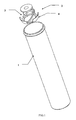
- the figure 1 represents a perspective view of the tubular container and the compensation device according to the invention before insertion.
- the tubular container is cylindrical.
- the figure 2 is a perspective view of a half of the container in a vertical section and truncated at its upper part comprising the compensation device according to the invention inserted at the bottom of the container.
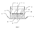
- the figure 3 is a sectional view of the compensation device according to the invention, in a variant equipped with a housing containing a desiccant integrated in said device.
- the figure 1 represents the tubular container (1) with its compensation device (2) not yet inserted, but without its closure means.
- the compensation device consists of a compensation means (3) and a fixing means (4).
- the figure 2 represents the compensation device (2) inserted at the bottom (9) of the container (1) empty of its contents ,.
- the compensation device (2) consists of a compensation means (3) and a fixing means (4).
- the compensating means (3) is hollow and conically shaped, consisting of a large circular base (8) inserted at the bottom (9) of the container (1) and a small circular base (5) on which the packaged products (not shown in this figure).
- the two bases of the compensation means are coaxial and connected by means of deformable links (7) which have the form of helical strands.
- the fixing means (4) consists of three mechanical elements (6) which are in the form of fins.
- the figure 3 represents a variant of the compensation device (2) comprising a compensation means (3) and a fixing means (4), and a housing (10) constituting an integral part of the device and making it possible to use a desiccant material (11); ).
- the compensation means (3) is hollow and cylindrical in shape, composed of a large circular base (8) inserted at the bottom of the container (not shown) and a small circular base (5).
- the two bases of the compensation means (3) are coaxial and connected by means of deformable links (7) which have the form of helical strands.
- the fixing means (4) consists of the mechanical elements (6) which are in the form of fins.
- the housing (10) is an integral part of the device (2), the bottom of the housing (10) being part of the large base (8), the cylindrical side walls of the housing (10) being of a diameter such that the compensation means (3) can freely play its function.
- a porous membrane (12) retained by crimping keeps the desiccant (11) in position.
Abstract
Description
La présente invention concerne un conteneur tubulaire, fermé à sa partie supérieure par un moyen d'obturation de type bouchon refermable y compris à charnière, muni d'un dispositif de compensation.The present invention relates to a tubular container, closed at its upper part by closure means of the closable cap type including hinge, provided with a compensation device.
L'invention concerne plus particulièrement un conteneur de ce type destiné notamment à conditionner des produits à usage pharmaceutique, cosmétique, alimentaire, vétérinaire, de diagnostique ou encore phytosanitaire, pouvant se présenter sous diverses formes telles que par exemples, des pastilles, des comprimés, des cachets, des tablettes. Ces produits conditionnés peuvent être empilés axialement à l'intérieur du conteneur tubulaire, les dimensions internes de ce dernier correspondant sensiblement aux dimensions externes des produits conditionnés ou bien être en vrac à l'intérieur dudit conteneur.The invention relates more particularly to a container of this type intended in particular to package products for pharmaceutical, cosmetic, food, veterinary, diagnostic or phytosanitary purposes, which may be in various forms such as, for example, pellets, tablets, tablets, tablets. These packaged products can be stacked axially inside the tubular container, the internal dimensions of the latter corresponding substantially to the external dimensions of the packaged products or be loose within said container.
Les produits conditionnés mentionnés ci-dessus ont souvent une structure poreuse et friable, en particulier lorsqu'il s'agit de comprimés effervescents, ce qui les rend particulièrement fragiles aux chocs et à l'abrasion. Cette détérioration mécanique est souvent occasionnée lors de la manutention et du transport de ces produits conditionnés dans des tubes eux-mêmes stockés dans des caisses ou des cartons, au cours desquels les chocs ou les secousses sont inévitables.The packaged products mentioned above often have a porous and friable structure, especially when it comes to effervescent tablets, which makes them particularly fragile to shocks and abrasion. This mechanical deterioration is often caused during the handling and transportation of these packaged products in tubes themselves stored in crates or boxes. cartons, during which shocks or shocks are inevitable.
Il a déjà été proposé de maintenir en position lesdits produits dans un conteneur tubulaire, plein ou sensiblement plein, grâce à un dispositif de compensation ayant la forme d'un ressort ou d'une vrille. Ainsi, les produits conditionnés ne peuvent plus bouger de manière intempestive à l'intérieur du conteneur lors du transport.It has already been proposed to hold said products in position in a tubular container, solid or substantially full, thanks to a compensation device in the form of a spring or a twist. Thus, the packaged products can not move inadvertently inside the container during transport.
De plus, de tels dispositifs de compensation permettent de compenser les écarts de cote d'épaisseur des produits unitaires conditionnés, ou de conditionner dans un même conteneur des produits d'épaisseurs différentes, à l'origine d'un jeu inéluctable existant entre le fond du moyen d'obturation et la face supérieure de la pile de produits conditionnés dans le conteneur. Toute liberté de déplacement à l'intérieur d'un tel espace est une source possible de détérioration desdits produits conditionnés.In addition, such compensation devices make it possible to compensate for differences in the thickness dimension of the packaged unit products, or to pack in one and the same container products of different thicknesses, at the origin of an unavoidable clearance existing between the bottom shutter means and the upper face of the stack of products packaged in the container. Any freedom of movement within such a space is a possible source of deterioration of said packaged products.
Quatre documents reflétant particulièrement l'état de la technique la plus proche dans ce domaine ont été sélectionnés, et sont décrits ci-après. Ils exposent différentes solutions de maintien des produits conditionnés dans un conteneur tubulaire à l'aide d'un dispositif de compensation.Four documents particularly reflecting the closest state of the art in this field have been selected, and are described below. They expose different solutions for keeping packaged products in a tubular container using a compensation device.
Un premier document (
Ce premier document présente un dispositif de compensation de type ressort élastique, ce dernier étant fixé soit sur le fond du conteneur soit sur la surface interne de son moyen d'obturation par surmoulage, ce qui engendre une certaine cohésion entre matériaux.This first document has a resilient spring type compensation device, the latter being fixed either on the bottom of the container or on the inner surface of its overmolding closure means, which generates a certain cohesion between materials.
Un deuxième document, le document
Ce document propose ainsi un dispositif de compensation sous la forme d'un ressort qui contribue aussi à l'extraction des comprimés, du fait de la détente dudit ressort et qui permet une extraction latérale du comprimé situé sur le dessus de la pile. Ce dispositif de compensation se compose de deux pièces différentes, à savoir un ressort et un plateau.This document thus proposes a compensation device in the form of a spring which also contributes to the extraction of the tablets, because of the expansion of said spring and which allows a lateral extraction of the tablet located on the top of the stack. This compensation device consists of two different parts, namely a spring and a plate.
Un troisième document, le document
Ce document présente le même dispositif de compensation que le document
Enfin, un quatrième document, le document
Ce document décrit un tube d'emballage équipé d'un dispositif de compensation dont la conception du panier suspendu paraît complexe du point de vue du moulage.This document describes a packaging tube equipped with a compensation device whose design of the suspended basket seems complex from the point of view of molding.
Au vu de l'état de la technique décrit ci-dessus, les dispositifs de compensation sont souvent de conception complexe quant à leur forme. De plus, ils sont généralement réalisés pour s'adapter de manière tout à fait spécifique aux dimensions d'un conteneur donné, ou le cas échéant d'un bouchon donné, dans lequel ils doivent être insérés.
Ainsi, la réalisation d'un dispositif de compensation apparaît dépendre des caractéristiques, en particulier des dimensions, du conteneur ou du bouchon dans lequel il doit être inséré, et engendre des coûts de fabrication élevés du fait qu'un seul dispositif de compensation ne peut être utilisé que pour un seul conteneur donné; ces coûts venant s'ajouter à ceux de l'élaboration de formes complexes du dispositif de compensation.In view of the state of the art described above, the compensation devices are often of complex design as to their shape. In addition, they are generally made to adapt in a very specific manner to the dimensions of a given container, or if necessary a given plug, in which they must be inserted.
Thus, the production of a compensation device appears to depend on the characteristics, in particular on the dimensions, of the container or plug in which it is to be inserted, and generates high manufacturing costs because only one compensation device can be used for only one given container; these costs are added to those of the development of complex forms of the compensation device.
Il y a donc un problème technique posé et non résolu, qui est celui de ne pouvoir réaliser un dispositif de compensation de réalisation aisée et pouvant s'adapter à de multiples conteneurs tubulaires de dimensions et de diamètres voisins lorsqu'ils sont de section circulaire, tout en assurant aussi une protection suffisante des produits conditionnés à l'encontre des chocs ou secousses occasionnés lors du transport ou de la manutention.There is therefore a technical problem that has been posed and not solved, which is that of not being able to produce a compensation device that is easy to produce and that can be adapted to multiple tubular containers of similar dimensions and diameters when they are of circular section. while also ensuring sufficient protection of the packaged products against shocks or jolts caused during transport or handling.
Un autre problème posé au concepteur est de proposer un conteneur tubulaire équipé d'un dispositif de compensation sous la forme d'une pièce moulée indépendante dudit conteneur et s'insérant aisément et de manière à ce qu'il devienne solidaire de celui-ci. L'insertion du dispositif de compensation dans le conteneur tubulaire pouvant être réalisée :
- avant l'introduction des produits conditionnés, ou
- conjointement avec ces derniers.
Un autre problème technique souvent mal résolu et à résoudre est celui de conteneurs tubulaires clos par un bouchon de type à charnière dont le mouvement d'ouverture-fermeture est gêné, voire empêché quand ledit bouchon est muni d'un dispositif de compensation, pour ce faire, la hauteur dudit dispositif de compensation doit être réduite, ce qui provoque une perte d'efficacité de l'action de compensation.
- before the introduction of packaged products, or
- jointly with them.
Another technical problem often badly solved and to be solved is that of tubular containers closed by a hinge-type plug whose opening-closing movement is obstructed or even prevented when said plug is provided with a compensation device, for which to do, the height of said compensation device must be reduced, which causes a loss of efficiency of the compensation action.
Dès lors, l'objet principal consiste à réaliser un conteneur tubulaire équipé d'un dispositif de compensation tel que:
- ce dernier puisse s'adapter à de multiples conteneurs de dimensions et de diamètres voisins lorsque le conteneur est de section circulaire,
- sa forme, de conception peu complexe, permette une insertion aisée et définitive au fond dudit conteneur, et ce avant l'introduction des produits conditionnés ou conjointement avec ces derniers,
- sa position au fond dudit conteneur laisse une entière liberté pour le choix du type du moyen d'obturation, y compris à charnière.
- the latter can adapt to multiple containers of similar dimensions and diameters when the container is of circular section,
- its shape, of uncomplicated design, allows an easy and definitive insertion in the bottom of said container, and before the introduction of the packaged products or jointly with them,
- its position at the bottom of said container leaves complete freedom for the choice of the type of closure means, including hinged.
Dès lors l'invention concerne un conteneur tubulaire, fermé à sa partie supérieure par un moyen d'obturation de type bouchon y compris à charnière, pour le conditionnement de produits unitaires empilés axialement ou en vrac tels que pastilles, comprimés, cachets, tablettes, et muni d'un dispositif de compensation, positionné au fond dudit conteneur, ledit conteneur comprenant éventuellement un moyen déshydratant, ledit dispositif de compensation étant constitué :
- d'un moyen de compensation muni à ses extrémités d'une grande base et d'une petite base qui est au plus égale à la grande base, et sur l'une desquelles reposent les produits conditionnés, et
- d'un moyen de fixation,
- est solidaire du moyen de compensation,
- et se compose d'éléments mécaniques, à mémoire de forme qui, après leur déformation élastique consécutive à l'insertion dudit dispositif de compensation dans le fond du conteneur, rendent solidaire le dispositif de compensation dudit conteneur en exerçant sur la paroi latérale interne du conteneur une force de friction perpendiculaire à ladite paroi.
- a compensation means provided at its ends with a large base and a small base which is at most equal to the large base, and on one of which the packed products rest, and
- a fastening means,
- is integral with the compensation means,
- and consists of mechanical elements, shape memory which, after their elastic deformation consecutive to the insertion of said compensation device in the bottom of the container, make integral the compensation device of said container by exerting on the inner side wall of the container a friction force perpendicular to said wall.
Le conteneur tubulaire selon l'invention est destiné au conditionnement de produits solides, stockés à l'intérieur dudit conteneur sous la forme d'un empilement axial ou en vrac. Le conteneur selon l'invention peut être utilisé pour le conditionnement de produits à usage pharmaceutique, cosmétique, alimentaire, vétérinaire, de diagnostique ou phytosanitaire.The tubular container according to the invention is intended for the packaging of solid products, stored inside said container in the form of an axial stack or in bulk. The container according to the invention can be used for the packaging of products for use pharmaceutical, cosmetic, food, veterinary, diagnostic or phytosanitary.
Lorsque l'empilement des produits conditionnés est axial, les dimensions internes du conteneur tubulaire correspondent sensiblement aux dimensions externes desdits produits conditionnés. L'empilement axial des produits conditionnés est préféré à l'entassement en vrac.When the stack of packaged products is axial, the internal dimensions of the tubular container substantially correspond to the external dimensions of said packaged products. Axial stacking of packaged products is preferred over bulk packing.
Avantageusement, le conteneur tubulaire peut être de section polygonale, elliptique, circulaire, et est préférentiellement de section circulaire.Advantageously, the tubular container may be of polygonal, elliptical, circular section, and is preferably of circular section.
De tels produits unitaires conditionnés tels que des pastilles, des comprimés, peuvent être friables, si bien que leur maintien en position est primordial afin d'éviter tout risque de détérioration par effet mécanique, en particulier de choc ou d'abrasion.Such packaged unit products such as tablets and tablets can be friable, so that their holding in position is essential in order to avoid any risk of deterioration by mechanical effect, in particular shock or abrasion.
Le conteneur tubulaire est fermé à sa partie supérieure par un moyen d'obturation de type bouchon refermable, y compris à charnière, de telle sorte que lorsque ledit conteneur est rempli ou quasi-rempli, le dispositif de compensation dont est muni le conteneur, exerce son action de compensation sur les produits conditionnés et les maintient en position, évitant ainsi tout risque de détérioration.The tubular container is closed at its upper part by a closure means of closable cap type, including hinged, so that when said container is filled or almost filled, the compensation device which is provided with the container, exerts its compensation action on the packaged products and keeps them in position, thus avoiding any risk of deterioration.
Le conteneur tubulaire selon l'invention est muni d'un dispositif de compensation, positionné au fond dudit conteneur, et qui est constitué :
- d'un moyen de compensation,
- d'un moyen de fixation.
- a compensation means,
- a fastening means.
Le moyen de compensation et le moyen de fixation sont rendus solidaires l'un de l'autre.The compensation means and the fixing means are secured to one another.
Le moyen de fixation est rendu solidaire du moyen de compensation par collage, soudage, co-injection ou injection conduisant à un ensemble monobloc. Le moyen de compensation et le moyen de fixation sont coaxiaux.The fixing means is secured to the compensation means by gluing, welding, co-injection or injection leading to a one-piece assembly. The compensation means and the fixing means are coaxial.
Le moyen de compensation du dispositif de compensation est creux et de forme apparente cylindrique, conique, tronconique, polyédrique, polyédrique tronquée, composé d'une grande base et d'une petite base parallèle à la grande base. Indifféremment la petite base ou la grande base est en contact avec les produits conditionnés, la grande base ou la petite base étant alors en contact avec le fond du conteneur. Le moyen de fixation est toujours solidaire de la base en contact avec le fond du conteneur, que ce soit la grande base ou la petite base. Ces deux bases sont coaxiales et sont reliées par au moins un moyen de liaison déformable sous l'effet d'une pression mécanique, et qui a capacité à recouvrer sa forme initiale lorsque ladite pression est supprimée.The compensation means of the compensation device is hollow and of apparent cylindrical, conical, frustoconical, polyhedral, truncated polyhedral form, composed of a large base and a small base parallel to the large base. Regardless, the small base or the large base is in contact with the packaged products, the large base or the small base then being in contact with the bottom of the container. The fastening means is always integral with the base in contact with the bottom of the container, whether the large base or the small base. These two bases are coaxial and are connected by at least one deformable connecting means under the effect of a mechanical pressure, and which has the ability to recover its initial shape when said pressure is removed.
La grande base et la petite base du moyen de compensation peuvent être de formes différentes ou non, mais dans tous les cas ces différentes formes doivent être insérables dans le conteneur tubulaire et adaptées à la section dudit conteneur.The large base and the small base of the compensation means may be of different shapes or not, but in all cases these different forms must be insertable into the tubular container and adapted to the section of said container.
Dans un mode de réalisation particulier, ladite section du conteneur est polygonale, elliptique ou circulaire.In a particular embodiment, said container section is polygonal, elliptical or circular.
Le moyen de compensation est de hauteur suffisante pour que son action mécanique de compensation puisse effectivement s'exercer. Ainsi, lorsque le conteneur selon l'invention est rempli ou quasi-rempli des produits conditionnés et obturé par son moyen d'obturation, le moyen de compensation exerce son action de compensation sur les produits conditionnés, de telle sorte qu'ils soient maintenus en position à l'intérieur dudit conteneur.The compensation means is of sufficient height so that its mechanical compensation action can actually be exercised. Thus, when the container according to the invention is filled or almost filled with the packaged products and closed by its sealing means, the compensation means exerts its compensation action on the packaged products, so that they are maintained in position inside said container.
La forme apparente du moyen de compensation, c'est-à-dire le volume fictif dans lequel ledit moyen de compensation est contenu, c'est-à-dire son encombrement stérique, peut être cylindrique, conique, tronconique, polyédrique ou polyédrique tronqué.The apparent shape of the compensation means, that is to say the imaginary volume in which said compensation means is contained, that is to say its steric hindrance, can be cylindrical, conical, frustoconical, polyhedral or truncated polyhedral .
Le moyen de liaison déformable de la grande base à la petite base peut être formé par :
- au moins une hélice déformable s'enroulant sur un cylindre ou cône fictif et coaxiale à l'axe de symétrie du moyen de compensation, et apparaissant comme un ressort cylindrique, tronconique ou conique ou,
- au moins une languette déformable apparaissant comme l'une des arêtes des faces du polyèdre fictif dans lequel s'inscrit le moyen de compensation ou appartenant à la surface fictive d'un cône ou d'un tronc de cône.
- at least one deformable helix winding on a cylinder or imaginary cone and coaxial with the axis of symmetry of the compensation means, and appearing as a cylindrical, frustoconical or conical spring or,
- at least one deformable tongue appearing as one of the edges of the faces of the fictional polyhedron in which the compensation means is inscribed or belonging to the imaginary surface of a cone or a truncated cone.
Le moyen de compensation, lorsque contenu dans un volume fictif cylindrique, conique, tronconique, polyédrique ou polyédrique tronqué peut comporter plusieurs moyens de liaison déformables au nombre de 2, 3, 4 ou plus et disposés autour de l'axe de symétrie du moyen de compensation.
En particulier, lorsque le volume fictif est polyédrique ou polyédrique tronqué, l'une des arêtes est constituée par le au moins un moyen de liaison déformable réel, reliant la grande base à la petite base, les autres arêtes étant fictives.The compensating means, when contained in a cylindrical, conical, frustoconical, polyhedral or truncated polyhedral fictitious volume may comprise a plurality of deformable connecting means of 2, 3, 4 or more and arranged around the axis of symmetry of the means of compensation.
In particular, when the fictitious volume is truncated polyhedral or polyhedral, one of the edges is constituted by the at least one real deformable connecting means, connecting the large base to the small base, the other edges being fictitious.
De manière illustrative, quand le volume fictif est polyédrique ou polyédrique tronqué, il comporte au minimum trois surfaces latérales dont les trois arêtes réelles sont constituées par trois moyens de liaison déformables. Il en est de même pour 4 faces, 5 faces, 6 faces.Illustratively, when the fictitious volume is truncated polyhedral or polyhedral, it comprises at least three lateral surfaces whose three real edges are constituted by three deformable connecting means. It is the same for 4 faces, 5 faces, 6 faces.
Quand le au moins un moyen de liaison déformable est formé par au moins deux hélices, lesdites hélices sont à sens opposés ou non et régulièrement réparties symétriquement par rapport à l'axe de symétrie du moyen de compensation.When the at least one deformable connecting means is formed by at least two propellers, said propellers are in opposite or opposite directions and regularly distributed symmetrically with respect to the axis of symmetry of the compensation means.
Dans le cas où, par exemple, le moyen de compensation comporte trois hélices, ces hélices peuvent être de même sens, ou bien, deux hélices peuvent être dans le même sens et la troisième hélice dans l'autre sens.In the case where, for example, the compensation means comprises three helices, these helices may be in the same direction, or two helices may be in the same direction and the third helix in the other direction.
Cette au moins une hélice est reliée, par son extrémité inférieure, à l'une des bases, qui est positionnée par exemple dans le fond du conteneur. Cette au moins une hélice est également reliée, par son extrémité supérieure, à l'autre base par exemple en contact physique avec le produit conditionné.This at least one helix is connected, by its lower end, to one of the bases, which is positioned for example in the bottom of the container. This at least one helix is also connected, by its upper end, at the other base for example in physical contact with the packaged product.
La section de cette au moins une hélice peut être circulaire ou polygonale.The section of this at least one helix may be circular or polygonal.
D'autres formes d'hélices peuvent être considérées, telles que, par exemple, des hélices à contre sens de rotation ou de forme non pas strictement conique mais légèrement rhomboïde.Other forms of helix may be considered, such as, for example, propellers against rotation direction or shape not strictly conical but slightly rhomboid.
Quand le au moins un moyen de liaison déformable est formé par au moins deux languettes, lesdites languettes sont réparties symétriquement par rapport à l'axe de symétrie du moyen de compensation. Cette au moins une languette est reliée, par son extrémité inférieure à l'une des bases, par exemple la grande base, qui est positionnée par exemple au fond du conteneur, et par son extrémité supérieure à l'autre base en contact physique avec le produit conditionné.When the at least one deformable connecting means is formed by at least two tabs, said tabs are distributed symmetrically with respect to the axis of symmetry of the compensation means. This at least one tongue is connected, by its lower end to one of the bases, for example the large base, which is positioned for example at the bottom of the container, and by its upper end to the other base in physical contact with the conditioned product.
Ledit moyen de compensation assure ainsi, par sa capacité à être comprimé et par son effet ressort, le maintien en position des produits conditionnés. La section des languettes est suffisamment fine, qu'elles soient circulaires ou polygonales, pour que lesdites languettes puissent se déformer de manière réversible, sous l'effet de la pression exercée sur elles lors de la fermeture du conteneur rempli.Said compensation means thus ensures, by its ability to be compressed and by its spring effect, the holding in position of the packaged products. The section of the tongues is sufficiently thin, whether circular or polygonal, so that said tongues can deform in a reversible manner, under the effect of the pressure exerted on them during the closure of the filled container.
L'effet ressort reste entier dans le temps, dans la mesure où les déformations restent dans la plage des déformations élastiques réversibles et qu'il n'y pas fluage des matériaux constitutifs du moyen de compensation. La pression exercée sur la pile de produits conditionnés par le moyen de compensation reste inchangée.The spring effect remains intact in time, insofar as the deformations remain in the range of the reversible elastic deformations and that there is no creep of the constituent materials of the compensation means. The pressure exerted on the stack of products packaged by the compensation means remains unchanged.
Le moyen de compensation, avec sa forme apparente conique ou polyédrique déformable, mais à mémoire de forme initiale, conserve toujours sa fonction de compensateur à effet ressort.The compensation means, with its deformable conical or polyhedral apparent shape, but with initial shape memory, still retains its function of spring compensator.
Le dispositif de compensation comporte également un moyen de fixation.The compensation device also comprises a fixing means.
Le moyen de fixation du dispositif de compensation à mémoire de forme et présentant une capacité à déformation élastique, exerce une force de friction perpendiculaire à la paroi latérale interne du conteneur est pour ce faire formé d'éléments mécaniques, lesdits éléments mécaniques peuvent être en particulier choisis dans le groupe constitué par les ailettes, les panneaux, les lames.The fixing means of the shape memory compensating device and having an elastic deformation capacity, exerts a friction force perpendicular to the inner side wall of the container is to this end formed of mechanical elements, said mechanical elements can be in particular selected from the group consisting of fins, panels, blades.
Le moyen de fixation comporte au moins trois éléments mécaniques. Les au moins trois éléments mécaniques du moyen de fixation sont rendus solidaires du moyen de compensation tangentiellement à la périphérie de la base au contact du fond du conteneur dudit moyen de compensation et répartis symétriquement par rapport à l'axe de symétrie du dispositif de compensation, de telle sorte que l'ensemble des forces de friction qu'ils engendrent avec la paroi latérale interne du conteneur rendent solidaire le dispositif de compensation du conteneur tubulaire.The fixing means comprises at least three mechanical elements. The at least three mechanical elements of the fastening means are made integral with the compensation means tangentially to the periphery of the base in contact with the bottom of the container of said compensation means and distributed symmetrically with respect to the axis of symmetry of the compensation device, such that all of the frictional forces they generate with the inner side wall of the container make integral the compensation device of the tubular container.
Ainsi, de manière tout à fait avantageuse, une fois le dispositif de compensation positionné au fond du conteneur, ledit conteneur peut être retourné sans que le dispositif de compensation ne s'en échappe.Thus, quite advantageously, once the compensation device positioned at the bottom of the container, said container can be returned without the compensation device does not escape.
Les au moins trois éléments mécaniques du moyen de fixation, au repos et avant leur insertion dans le conteneur, définissent par leur extrémité non solidaire du moyen de compensation, un contour apparent dont la plus grande dimension, définie par la distance la plus grande entre deux points en opposition dudit contour, est comprise entre 1,1 et 2,0 fois la plus grande dimension mesurée dans le plan de section perpendiculaire à l'axe de symétrie longitudinal du conteneur.The at least three mechanical elements of the fastening means, at rest and before their insertion into the container, define by their non-integral end of the compensation means, an apparent contour whose largest dimension, defined by the largest distance between two points in opposition to said contour, is between 1.1 and 2.0 times the largest dimension measured in the sectional plane perpendicular to the longitudinal axis of symmetry of the container.
Dans le cas où la section du conteneur est polygonale, la plus grande dimension apparente est:
- pour une section triangulaire équilatérale, l'un des côtés du triangle,
- pour une section carrée, une diagonale,
- pour une section rectangulaire la diagonale la plus grande,
Dans le cas où la section est elliptique, la plus grande dimension apparente est le plus grand axe elliptique.In the case where the container section is polygonal, the largest apparent dimension is:
- for an equilateral triangular section, one of the sides of the triangle,
- for a square section, a diagonal,
- for a rectangular section the largest diagonal,
In the case where the section is elliptical, the largest apparent dimension is the largest elliptical axis.
Dans le cas où la section est circulaire, la plus grande dimension apparente est le diamètre.In the case where the section is circular, the largest apparent dimension is the diameter.
Les au moins trois éléments mécaniques du moyen de fixation, au repos et avant leur insertion dans le conteneur, définissent par leur extrémité non solidaire du moyen de compensation, un contour apparent dont la plus grande dimension, définie par la distance la plus grande entre deux points en opposition dudit contour, est préférentiellement comprise entre 1,2 et 1,6 fois la plus grande dimension mesurée dans le plan de section perpendiculaire à l'axe de symétrie longitudinal du conteneur.The at least three mechanical elements of the fastening means, at rest and before their insertion into the container, define by their non-integral end of the compensation means, an apparent outline whose most large dimension, defined by the largest distance between two points in opposition to said contour, is preferably between 1.2 and 1.6 times the largest dimension measured in the section plane perpendicular to the longitudinal axis of symmetry of the container .
Les au moins trois éléments mécaniques du moyen de fixation ont une hauteur, lorsque le dispositif de compensation est inséré dans le conteneur, au plus égale à 0,5 fois la hauteur du moyen de compensation.The at least three mechanical elements of the fastening means have a height, when the compensation device is inserted into the container, at most equal to 0.5 times the height of the compensation means.
Les au moins trois éléments mécaniques du moyen de fixation sont des parois minces formant des surfaces planes ou courbes.The at least three mechanical elements of the fastening means are thin walls forming flat or curved surfaces.
Ainsi, une fois le dispositif de compensation positionné au fond du conteneur tubulaire, les au moins trois éléments mécaniques élastiques s'étant redéployés jusqu'à être en contact surface à surface avec la paroi latérale interne du conteneur, exerce des forces de friction sur ladite paroi latérale interne, ce qui assure une tenue en position dudit dispositif de compensation dans le conteneur tubulaire.Thus, once the compensation device positioned at the bottom of the tubular container, the at least three elastic mechanical elements redeployed to be in surface-to-surface contact with the inner side wall of the container, exerts frictional forces on said internal side wall, which ensures a holding position of said compensation device in the tubular container.
Outre l'avantage mentionné ci-dessus d'une fiabilité de tenue en position au fond du conteneur de ce dispositif de compensation, et ce même en l'absence du moyen d'obturation et/ou des produits conditionnés, il est à noter les autres caractéristiques avantageuses de ce dispositif de compensation.In addition to the above-mentioned advantage of a position-holding reliability at the bottom of the container of this compensation device, even in the absence of the sealing means and / or the packaged products, it is worth noting the other advantageous features of this compensation device.
Les au moins trois éléments mécaniques du moyen de fixation peuvent éventuellement chacun comporter une protubérance en forme de segment de joncs venant s'ajuster dans une rainure correspondante positionnée sur la surface interne du conteneur. Cette association de segments de joncs et de rainure permet de fixer de manière encore plus définitive le dispositif de compensation inséré dans le conteneur.The at least three mechanical elements of the fixing means may optionally each comprise a protuberance in the form of segment of rods fitting into a corresponding groove positioned on the inner surface of the container. This combination of segments of rushes and groove makes it possible to fix even more definitively the compensation device inserted in the container.
Tout d'abord, le dispositif de compensation peut être introduit avant les produits conditionnés dans le conteneur, ou bien conjointement aux produits conditionnés.First, the compensation device can be introduced before the packaged products in the container, or in conjunction with the packaged products.
Ainsi, le déroulement des étapes de manutention du conteneur équipé de ce dispositif de compensation selon l'invention est simplifié.Thus, the steps of handling steps of the container equipped with this compensation device according to the invention is simplified.
De plus, du fait de l'élasticité des au moins trois éléments mécaniques constituant le moyen de fixation du dispositif de compensation, ce dispositif de compensation peut s'adapter à des conteneurs tubulaires de dimensions et de diamètres voisins lorsque le conteneur est de section circulaire.In addition, because of the elasticity of the at least three mechanical elements constituting the fixing means of the compensation device, this compensation device can adapt to tubular containers of similar dimensions and diameters when the container is of circular section. .
Ainsi, ce dispositif de compensation peut être intégré à différents conteneurs, offrant une souplesse d'utilisation, et permettant de se dégager de la contrainte d'élaboration d'un dispositif de compensation propre à chaque type de conteneur.Thus, this compensation device can be integrated with different containers, offering a flexibility of use, and to get rid of the constraint of developing a specific compensation device for each type of container.
Tous ces avantages mentionnés ci-dessus permettent de limiter les coûts de fabrication de conteneurs munis de ce dispositif de compensation.All these advantages mentioned above make it possible to limit the costs of manufacturing containers equipped with this compensation device.
D'une manière générale, le conteneur, le moyen d'obturation et le dispositif de compensation peuvent être réalisés à partir de polymères identiques ou différents.
Les polymères mis en oeuvre sont généralement choisis dans le groupe formé par les polyoléfines homo et/ou copolymères tels que les polyéthylènes, les polypropylènes, les copolymères d'éthylène/propylène mis en oeuvre seuls ou en mélange, formulés ou non.
D'autres polymères thermoplastiques peuvent également être utilisés tels que les polyamides (PA), les polystyrènes (PS), les copolymères d'acrylonitrile-butadiène-styrène (ABS), les copolymères de styrène-acrylonitrile (SAN), les polyméthacrylates de méthyl (PMMA), les polyéthylènetéréphtalates (PET), les polybutylènetéréphtalates (PBT), les polyacétals (POM), les polychlorures de vinyle (PVC), les polycarbonates (PC).In general, the container, the sealing means and the compensation device may be made from identical or different polymers.
The polymers used are generally chosen from the group formed by homo and / or copolymeric polyolefins such as polyethylenes, polypropylenes and ethylene / propylene copolymers used alone or in a mixture, formulated or not.
Other thermoplastic polymers may also be used such as polyamides (PA), polystyrenes (PS), acrylonitrile-butadiene-styrene copolymers (ABS), styrene-acrylonitrile copolymers (SAN), polymethyl methacrylates (PMMA), polyethylene terephthalates (PET), polybutyleneterephthalates (PBT), polyacetals (POM), polyvinylchlorides (PVC), polycarbonates (PC).
Des élastomères de mono-oléfines tels que, par exemple, les polymères d'isobutylène/isoprène, éthylène-acétate de vinyle (EVA), éthylène-propylène (EPR), éthylène-propylène-diène (EPDM), éthylène-esters acryliques (EMA-EEA), les polymères fluorés, les caoutchouc de dioléfines, tels que, par exemple, les polybutadiène, les copolymères de butadiène-styrène (SBR), les caoutchoucs à base de produits de condensation tels que, par exemple, les caoutchoucs thermoplastiques polyesters et polyuréthanes, les silicones, les caoutchoucs styrèniques, tels que styrène-butadiène-styrène(SBS), les styrène-isoprène-styrène (SIS), les styrène-ethylène butadiène-styrène (SEBS) et autres copolymères bloc, et plus généralement les élastomères thermoplastiques, mis en oeuvre seuls ou en mélange, avec en particulier les polymères thermoplastiques précités, formulés ou non, peuvent également être utilisés.Monoolefin elastomers such as, for example, isobutylene / isoprene, ethylene-vinyl acetate (EVA), ethylene-propylene (EPR), ethylene-propylene-diene (EPDM) polymers, ethylene-acrylic esters ( EMA-EEA), fluorinated polymers, diolefin rubbers, such as, for example, polybutadiene, butadiene-styrene copolymers (SBR), rubbers based on condensation products such as, for example, thermoplastic rubbers polyesters and polyurethanes, silicones, styrene rubbers, such as styrene-butadiene-styrene (SBS), styrene-isoprene-styrene (SIS), styrene-ethylene-butadiene-styrene (SEBS) and other block copolymers, and more generally thermoplastic elastomers, implemented alone or in a mixture, with in particular the aforementioned thermoplastic polymers, formulated or not, may also be used.
Ainsi, le dispositif de compensation décrit dans la présente invention simplifie la mise en oeuvre et la conception de conteneurs tubulaires destinés à conditionner des produits fragiles, tels que des comprimés pharmaceutiques, tout en assurant la fonction de tenue en position à l'intérieur dudit conteneur.Thus, the compensation device described in the present invention simplifies the implementation and design of tubular containers for packaging fragile products, such as pharmaceutical tablets, while providing the position-holding function inside said container. .
Le conteneur tubulaire selon l'invention comprend éventuellement un moyen déshydratant qui peut être de type rapporté ou bien de type chemisage déshydratant.The tubular container according to the invention optionally comprises a desiccant means which can be of type reported or of the desiccant liner type.
Selon un autre mode de réalisation de l'invention, le dispositif de compensation peut aussi constituer un moyen déshydratant du conteneur tubulaire, s'il est fabriqué à partir d'une composition comprenant au moins une matière plastique thermoplastique ou thermodurcissable, et au moins un matériau déshydratant.According to another embodiment of the invention, the compensation device may also constitute a desiccant means of the tubular container, if it is manufactured from a composition comprising at least one thermoplastic or thermosetting plastic material, and at least one desiccant material.
Lorsque le moyen déshydratant est de type rapporté, l'agent déshydratant est placé dans un logement approprié, situé dans le bouchon, et/ou sur le fond du conteneur tubulaire, et/ou intégré au dispositif de compensation, ou faire partie intégrante du dit dispositif, ledit logement étant clos par un moyen de fermeture non étanche à l'humidité ambiante, par exemple, une membrane en carton poreux, pour assurer la dessiccation rapide des produits sensibles à l'humidité et conditionnés dans le conteneur tubulaire.When the desiccant means is of type reported, the desiccant is placed in a suitable housing, located in the cap, and / or on the bottom of the tubular container, and / or integrated in the compensation device, or an integral part of said device, said housing being closed by a sealing means not sealed to ambient humidity, for example a porous cardboard membrane, to ensure the rapid drying of the moisture-sensitive products and packaged in the container tubular.
L'agent déshydratant mis en oeuvre dans le conteneur est choisi dans le groupe constitué par les gels de silice, les tamis moléculaires ou autres produits déshydratants, se présentant sous une forme pulvérulente ou déposés sur un support pulvérulent.The dehydrating agent used in the container is selected from the group consisting of silica gels, molecular sieves or other desiccants, in powder form or deposited on a powdery support.
L'agent déshydratant peut également être une capsule contenue dans ledit logement et réalisée en un matériau polymère déshydratant contenant ou non des charges déshydratantes.The desiccant may also be a capsule contained in said housing and made of a desiccant polymer material containing or not desiccant fillers.
Lorsqu'un agent déshydratant est positionné dans un logement situé sur le fond du conteneur tubulaire, le dispositif de compensation est positionné en appui sur la membrane non étanche à l'humidité ambiante fermant le logement.When a desiccant is positioned in a housing located on the bottom of the tubular container, the compensation device is positioned in abutment on the non-moisture-tight membrane closing the housing.
Lorsque le moyen déshydratant est de type chemisage, il a alors une forme telle qu'il vient s'ajuster à l'intérieur du conteneur tubulaire. Cette forme est positionnée de manière coaxiale par rapport au conteneur, ajustée très précisément par rapport à la surface interne dudit conteneur, et pouvant glisser librement par rapport à celui-ci, ou être emmanché légèrement à force. Cette forme peut également venir en léger retrait de la surface interne du conteneur tubulaire, l'ajustement sur le conteneur se faisant alors par une pluralité de nervures longitudinales parallèles à l'axe du conteneur, assurant le centrage, ou éventuellement par l'intermédiaire de protubérances, correspondant à des nervures tronquées.When the desiccant means is of liner type, it then has a shape such that it fits inside the tubular container. This shape is positioned coaxially with respect to the container, adjusted very precisely relative to the inner surface of said container, and can slide freely relative thereto, or be forced slightly forcibly. This shape can also come in slight withdrawal from the inner surface of the tubular container, the adjustment on the container then being made by a plurality of longitudinal ribs parallel to the axis of the container, ensuring the centering, or possibly via protuberances, corresponding to truncated ribs.
Un tel chemisage peut avoir une dimension en hauteur identique à la profondeur du conteneur tubulaire et venir araser l'extrémité ouverte dudit conteneur ou être de dimension inférieure.Such a liner may have a height dimension identical to the depth of the tubular container and come to strike the open end of said container or be of smaller size.
Le chemisage peut également posséder un fond, venant ou non se poser sur le fond du conteneur tubulaire. Une cale d'espacement peut également permettre de laisser un espace entre le fond du conteneur et le fond de la chemise constituant le moyen déshydratant.The liner may also have a bottom, whether or not to land on the bottom of the tubular container. A spacer may also allow to leave a gap between the bottom of the container and the bottom of the jacket constituting the dehydrating means.
Cette chemise dessicante est fabriquée par les techniques d'injection à partir de compositions déshydratantes. Ces compositions déshydratantes sont généralement bien connues et amplement décrites sous la forme de compositions thermoplastiques injectables comprenant des matériaux polymères auxquels ont été incorporés des produits déshydratants.This desiccant liner is manufactured by injection techniques from desiccant compositions. These desiccant compositions are generally well known and widely described in the form of injectable thermoplastic compositions comprising polymeric materials into which desiccants have been incorporated.
Lorsque le moyen déshydratant est de type chemisage, le moyen de fixation du dispositif de compensation exerce des forces de friction sur la chemise déshydratante.When the desiccant means is of liner type, the fixing means of the compensation device exerts frictional forces on the desiccant liner.
Dans le mode de réalisation de l'invention pour lequel le dispositif de compensation est aussi un moyen déshydratant, ledit moyen déshydratant est réalisé avec les mêmes polymères et matériaux déshydratants que ceux mis en oeuvre pour la réalisation de la chemise déshydratante.In the embodiment of the invention for which the compensation device is also a dehydrating means, said desiccant means is made with the same polymers and desiccant materials as those implemented for the production of the desiccant jacket.
L'invention sera mieux comprise grâce à la description chiffrée des figures ci-après évoquées, ces figures n'ayant qu'un caractère illustratif non limitatif d'un dispositif particulier de l'invention.The invention will be better understood thanks to the numerical description of the figures below, these figures having only an illustrative non-limiting character of a particular device of the invention.
La
La
La
La
La
Le dispositif de compensation (2) est constitué d'un moyen de compensation (3) et d'un moyen de fixation (4).The compensation device (2) consists of a compensation means (3) and a fixing means (4).
Le moyen de compensation (3) est creux et de forme apparente conique, composé d'une grande base circulaire (8) insérée au fond (9) du conteneur (1) et d'une petite base circulaire (5) sur laquelle reposent les produits conditionnés (non représentés sur la présente figure). Les deux bases du moyen de compensation sont coaxiales et reliées par des moyens de liaisons déformables (7) qui ont la forme de brins hélicoïdaux.The compensating means (3) is hollow and conically shaped, consisting of a large circular base (8) inserted at the bottom (9) of the container (1) and a small circular base (5) on which the packaged products (not shown in this figure). The two bases of the compensation means are coaxial and connected by means of deformable links (7) which have the form of helical strands.
Le moyen de fixation (4) est constitué de trois éléments mécaniques (6) qui ont la forme d'ailettes.The fixing means (4) consists of three mechanical elements (6) which are in the form of fins.
La
Le moyen de compensation (3) est creux et de forme apparente cylindrique, composé d'une grande base circulaire (8) insérée au fond du conteneur (non représenté) et d'une petite base circulaire (5). Les deux bases du moyen de compensation (3) sont coaxiales et reliées par des moyens de liaisons déformables (7) qui ont la forme de brins hélicoïdaux.The
The compensation means (3) is hollow and cylindrical in shape, composed of a large circular base (8) inserted at the bottom of the container (not shown) and a small circular base (5). The two bases of the compensation means (3) are coaxial and connected by means of deformable links (7) which have the form of helical strands.
Le moyen de fixation (4) est constitué des éléments mécaniques (6) qui ont la forme d'ailettes. Le logement (10) fait, partie intégrante du dispositif (2), le fond du logement (10) étant partie de la grande base (8), les parois latérales cylindriques du logement (10) étant d'un diamètre tel que le moyen de compensation (3) peut librement jouer sa fonction. Une membrane poreuse (12) retenue par sertissage permet de maintenir en position le déshydratant (11).The fixing means (4) consists of the mechanical elements (6) which are in the form of fins. The housing (10) is an integral part of the device (2), the bottom of the housing (10) being part of the large base (8), the cylindrical side walls of the housing (10) being of a diameter such that the compensation means (3) can freely play its function. A porous membrane (12) retained by crimping keeps the desiccant (11) in position.
Claims (22)
Applications Claiming Priority (1)
| Application Number | Priority Date | Filing Date | Title |
|---|---|---|---|
| FR0702330A FR2914285B1 (en) | 2007-03-30 | 2007-03-30 | CLOSED TUBULAR CONTAINER COMPRISING A COMPENSATION DEVICE FOR PACKAGING COMPRESSES |
Publications (2)
| Publication Number | Publication Date |
|---|---|
| EP1990291A1 true EP1990291A1 (en) | 2008-11-12 |
| EP1990291B1 EP1990291B1 (en) | 2010-12-01 |
Family
ID=38671036
Family Applications (1)
| Application Number | Title | Priority Date | Filing Date |
|---|---|---|---|
| EP08004317A Active EP1990291B1 (en) | 2007-03-30 | 2008-03-08 | Closed tubular container including a compensation device for packaging tablets |
Country Status (5)
| Country | Link |
|---|---|
| US (1) | US8763797B2 (en) |
| EP (1) | EP1990291B1 (en) |
| AT (1) | ATE490197T1 (en) |
| DE (1) | DE602008003711D1 (en) |
| FR (1) | FR2914285B1 (en) |
Cited By (1)
| Publication number | Priority date | Publication date | Assignee | Title |
|---|---|---|---|---|
| CN109612562B (en) * | 2018-12-03 | 2021-01-05 | 江苏海宏信息科技有限公司 | Silo material weight metering system and method based on distributed weighing nodes |
Families Citing this family (8)
| Publication number | Priority date | Publication date | Assignee | Title |
|---|---|---|---|---|
| US9566380B1 (en) * | 2014-08-21 | 2017-02-14 | Robert K. Tcholakian | Reusable and inexpensive container assembly designed for storage of insulin ampules and other hypodermic solutions and pharmaceutical medications |
| US9072581B1 (en) * | 2014-09-25 | 2015-07-07 | King Saud University | Eye dropper positioning and guiding apparatus |
| US20210228442A1 (en) * | 2018-06-26 | 2021-07-29 | Abbvie Inc. | Medicine Container, Method of Assembling the Container, and Method of Manufacturing the Container |
| AU2019406613A1 (en) * | 2018-12-17 | 2021-06-10 | Glaxosmithkline Consumer Healthcare Holdings (Us) Llc | Child-resistant container |
| EP3674233A1 (en) | 2018-12-27 | 2020-07-01 | Clariant Plastics & Coatings Ltd | A tablet dispensing device |
| CN112388978B (en) * | 2019-08-16 | 2024-02-06 | 厦门鹏茂机械设备有限公司 | Forming method and structure of double-ended hose |
| CN111983161B (en) * | 2020-08-18 | 2023-02-28 | 天津市精诚光电科技有限公司 | Intelligent tablet four-purpose instrument |
| US11851259B2 (en) * | 2021-12-20 | 2023-12-26 | Travis Honda | Packaging system |
Citations (7)
| Publication number | Priority date | Publication date | Assignee | Title |
|---|---|---|---|---|
| US1671285A (en) * | 1924-02-14 | 1928-05-29 | Hanna John Paul | Dispensing package |
| US3826358A (en) * | 1972-05-10 | 1974-07-30 | Miles Lab | Package for tablets |
| DE8337183U1 (en) * | 1983-12-24 | 1986-01-09 | Friedrich Sanner GmbH & Co KG Spritzgußwerk, 6140 Bensheim | Tamper-evident locking arrangement |
| FR2694270A1 (en) | 1992-07-31 | 1994-02-04 | Pont De Nemours France Sa Du | Packaging tube esp. for pharmaceutical products - has internal suspended container to protect contents from shock and rupture. |
| FR2705646A1 (en) * | 1993-05-25 | 1994-12-02 | Airsec Ind Sa | Stopper with tamper-evident device for container with folded back or reinforced rim |
| US20050016873A1 (en) * | 2002-04-11 | 2005-01-27 | John Belfance | Desiccant vial assembly for effervescent tablets |
| EP1602596A2 (en) * | 2004-05-24 | 2005-12-07 | Istituto Pirri S.R.L. | Container for effervescent tablets |
Family Cites Families (6)
| Publication number | Priority date | Publication date | Assignee | Title |
|---|---|---|---|---|
| US2637462A (en) * | 1949-04-21 | 1953-05-05 | United Carr Fastener Corp | Closure member |
| ATE75456T1 (en) * | 1985-05-24 | 1992-05-15 | Sanner Friedr Gmbh Co Kg | CONTAINER CLOSURE. |
| FR2612161B1 (en) * | 1987-03-13 | 1989-06-23 | Air Sec Sa | PACKAGING TUBE FOR TABLETS, STAMPS OR THE LIKE, WITH RESERVE BOX |
| US6398051B1 (en) * | 2000-07-19 | 2002-06-04 | Owens-Illinois Closure Inc. | Tablet package including a tablet hold-down device |
| US6986807B2 (en) * | 2004-02-06 | 2006-01-17 | Brunk S Fred | Desiccant bottle cap |
| WO2008092470A1 (en) * | 2007-01-29 | 2008-08-07 | Egomedical Swiss Ag | Resealeable container for storing moisture sensitive test elements |
-
2007
- 2007-03-30 FR FR0702330A patent/FR2914285B1/en not_active Expired - Fee Related
-
2008
- 2008-03-08 AT AT08004317T patent/ATE490197T1/en not_active IP Right Cessation
- 2008-03-08 DE DE602008003711T patent/DE602008003711D1/en active Active
- 2008-03-08 EP EP08004317A patent/EP1990291B1/en active Active
- 2008-03-21 US US12/053,022 patent/US8763797B2/en active Active
Patent Citations (7)
| Publication number | Priority date | Publication date | Assignee | Title |
|---|---|---|---|---|
| US1671285A (en) * | 1924-02-14 | 1928-05-29 | Hanna John Paul | Dispensing package |
| US3826358A (en) * | 1972-05-10 | 1974-07-30 | Miles Lab | Package for tablets |
| DE8337183U1 (en) * | 1983-12-24 | 1986-01-09 | Friedrich Sanner GmbH & Co KG Spritzgußwerk, 6140 Bensheim | Tamper-evident locking arrangement |
| FR2694270A1 (en) | 1992-07-31 | 1994-02-04 | Pont De Nemours France Sa Du | Packaging tube esp. for pharmaceutical products - has internal suspended container to protect contents from shock and rupture. |
| FR2705646A1 (en) * | 1993-05-25 | 1994-12-02 | Airsec Ind Sa | Stopper with tamper-evident device for container with folded back or reinforced rim |
| US20050016873A1 (en) * | 2002-04-11 | 2005-01-27 | John Belfance | Desiccant vial assembly for effervescent tablets |
| EP1602596A2 (en) * | 2004-05-24 | 2005-12-07 | Istituto Pirri S.R.L. | Container for effervescent tablets |
Cited By (1)
| Publication number | Priority date | Publication date | Assignee | Title |
|---|---|---|---|---|
| CN109612562B (en) * | 2018-12-03 | 2021-01-05 | 江苏海宏信息科技有限公司 | Silo material weight metering system and method based on distributed weighing nodes |
Also Published As
| Publication number | Publication date |
|---|---|
| DE602008003711D1 (en) | 2011-01-13 |
| FR2914285B1 (en) | 2009-07-03 |
| US8763797B2 (en) | 2014-07-01 |
| EP1990291B1 (en) | 2010-12-01 |
| ATE490197T1 (en) | 2010-12-15 |
| FR2914285A1 (en) | 2008-10-03 |
| US20100252458A1 (en) | 2010-10-07 |
Similar Documents
| Publication | Publication Date | Title |
|---|---|---|
| EP1990291B1 (en) | Closed tubular container including a compensation device for packaging tablets | |
| EP2125553B1 (en) | Dehydrating and reclosable hinged plug-lid with tamper indicator and compensation device | |
| FR2858301A1 (en) | WATERPROOF DESSICATIVE CONTAINER FOR PACKAGING AMBIENT HUMIDITY-SENSITIVE PRODUCTS | |
| EP2699481B1 (en) | Isothermal packaging device for heat-sensitive products | |
| EP1601587A2 (en) | Device for dispensing oblong objects, comprising one main opening and at least one other elongated opening | |
| FR3063282A1 (en) | CONTAINER FOR MEDICAL AND / OR PHARMACEUTICAL PRODUCTS | |
| FR3046142A1 (en) | CONTAINER FOR STORAGE AND INDIVIDUAL DISCHARGE OF CAPSULES | |
| FR2948342A1 (en) | Insulated casing for storing and transporting e.g. food product, has external envelope adhered with internal envelopes of cover, base and wall by insert, where internal envelopes are formed from single piece made of metalized foam sheet | |
| FR2891259A1 (en) | MONOBLOC CONTAINER WITH HINGED COVER / COVER | |
| FR3080368A1 (en) | SHOCK PROTECTION DEVICE CAPABLE OF EQUIPPING BOTTLE | |
| EP1554180A2 (en) | Device which is used to transport a container in the vertical position, comprising packaging containing a gyroscopic system | |
| WO2006035073A1 (en) | Sealing closure device for a container | |
| WO1998038109A1 (en) | Packaging assembly comprising a shell sealed by blister pack | |
| FR2937017A1 (en) | Packaging box for e.g. compact disks, has cover with extension whose end is integrated to internal end of panel so that extension is displaced in translation in sleeve and induces translation movement to leave sleeve, when cover is raised | |
| EP1129957A1 (en) | Container having an integral hinge-lid | |
| FR2856041A1 (en) | ASSEMBLY OF SEMI-RIGID MATERIAL FOR THE PACKAGING OF AT LEAST ONE OBLONG, FRAGILE OBJECT, ESPECIALLY A BOTTLE. | |
| EP1431208B1 (en) | Packaging tray | |
| EP1714893B1 (en) | Wrapping for the packaging of an object | |
| FR3074786A1 (en) | PACKAGING BASE AND CLOCHE SOLIDARISES BY CLOSURE | |
| EP0485289A1 (en) | Packaging for dangerous products, fragile contaner | |
| FR2772730A1 (en) | DEVICE FOR PACKAGING AND TRANSPORTING LIQUID OR POWDER PRODUCTS | |
| WO2007028875A1 (en) | Pencil lead box | |
| EP3967624A1 (en) | Delivery tray and packaging system for medical items | |
| EP4116216A1 (en) | Device for sealing a tank of a liquid product | |
| FR2721906A1 (en) | Packaging unit for transporting and storing bottles, esp. wine bottles |
Legal Events
| Date | Code | Title | Description |
|---|---|---|---|
| PUAI | Public reference made under article 153(3) epc to a published international application that has entered the european phase |
Free format text: ORIGINAL CODE: 0009012 |
|
| 17P | Request for examination filed |
Effective date: 20080308 |
|
| AK | Designated contracting states |
Kind code of ref document: A1 Designated state(s): AT BE BG CH CY CZ DE DK EE ES FI FR GB GR HR HU IE IS IT LI LT LU LV MC MT NL NO PL PT RO SE SI SK TR |
|
| AX | Request for extension of the european patent |
Extension state: AL BA MK RS |
|
| AKX | Designation fees paid |
Designated state(s): AT BE BG CH CY CZ DE DK EE ES FI FR GB GR HR HU IE IS IT LI LT LU LV MC MT NL NO PL PT RO SE SI SK TR |
|
| GRAP | Despatch of communication of intention to grant a patent |
Free format text: ORIGINAL CODE: EPIDOSNIGR1 |
|
| GRAS | Grant fee paid |
Free format text: ORIGINAL CODE: EPIDOSNIGR3 |
|
| GRAA | (expected) grant |
Free format text: ORIGINAL CODE: 0009210 |
|
| AK | Designated contracting states |
Kind code of ref document: B1 Designated state(s): AT BE BG CH CY CZ DE DK EE ES FI FR GB GR HR HU IE IS IT LI LT LU LV MC MT NL NO PL PT RO SE SI SK TR |
|
| REG | Reference to a national code |
Ref country code: GB Ref legal event code: FG4D Free format text: NOT ENGLISH |
|
| REG | Reference to a national code |
Ref country code: CH Ref legal event code: EP |
|
| REG | Reference to a national code |
Ref country code: IE Ref legal event code: FG4D |
|
| REF | Corresponds to: |
Ref document number: 602008003711 Country of ref document: DE Date of ref document: 20110113 Kind code of ref document: P |
|
| REG | Reference to a national code |
Ref country code: NL Ref legal event code: VDEP Effective date: 20101201 |
|
| PG25 | Lapsed in a contracting state [announced via postgrant information from national office to epo] |
Ref country code: NO Free format text: LAPSE BECAUSE OF FAILURE TO SUBMIT A TRANSLATION OF THE DESCRIPTION OR TO PAY THE FEE WITHIN THE PRESCRIBED TIME-LIMIT Effective date: 20110301 Ref country code: LT Free format text: LAPSE BECAUSE OF FAILURE TO SUBMIT A TRANSLATION OF THE DESCRIPTION OR TO PAY THE FEE WITHIN THE PRESCRIBED TIME-LIMIT Effective date: 20101201 |
|
| LTIE | Lt: invalidation of european patent or patent extension |
Effective date: 20101201 |
|
| PG25 | Lapsed in a contracting state [announced via postgrant information from national office to epo] |
Ref country code: AT Free format text: LAPSE BECAUSE OF FAILURE TO SUBMIT A TRANSLATION OF THE DESCRIPTION OR TO PAY THE FEE WITHIN THE PRESCRIBED TIME-LIMIT Effective date: 20101201 Ref country code: CY Free format text: LAPSE BECAUSE OF FAILURE TO SUBMIT A TRANSLATION OF THE DESCRIPTION OR TO PAY THE FEE WITHIN THE PRESCRIBED TIME-LIMIT Effective date: 20101201 Ref country code: SI Free format text: LAPSE BECAUSE OF FAILURE TO SUBMIT A TRANSLATION OF THE DESCRIPTION OR TO PAY THE FEE WITHIN THE PRESCRIBED TIME-LIMIT Effective date: 20101201 Ref country code: FI Free format text: LAPSE BECAUSE OF FAILURE TO SUBMIT A TRANSLATION OF THE DESCRIPTION OR TO PAY THE FEE WITHIN THE PRESCRIBED TIME-LIMIT Effective date: 20101201 Ref country code: BG Free format text: LAPSE BECAUSE OF FAILURE TO SUBMIT A TRANSLATION OF THE DESCRIPTION OR TO PAY THE FEE WITHIN THE PRESCRIBED TIME-LIMIT Effective date: 20110301 Ref country code: HR Free format text: LAPSE BECAUSE OF FAILURE TO SUBMIT A TRANSLATION OF THE DESCRIPTION OR TO PAY THE FEE WITHIN THE PRESCRIBED TIME-LIMIT Effective date: 20101201 Ref country code: LV Free format text: LAPSE BECAUSE OF FAILURE TO SUBMIT A TRANSLATION OF THE DESCRIPTION OR TO PAY THE FEE WITHIN THE PRESCRIBED TIME-LIMIT Effective date: 20101201 Ref country code: NL Free format text: LAPSE BECAUSE OF FAILURE TO SUBMIT A TRANSLATION OF THE DESCRIPTION OR TO PAY THE FEE WITHIN THE PRESCRIBED TIME-LIMIT Effective date: 20101201 Ref country code: SE Free format text: LAPSE BECAUSE OF FAILURE TO SUBMIT A TRANSLATION OF THE DESCRIPTION OR TO PAY THE FEE WITHIN THE PRESCRIBED TIME-LIMIT Effective date: 20101201 |
|
| REG | Reference to a national code |
Ref country code: IE Ref legal event code: FD4D |
|
| PG25 | Lapsed in a contracting state [announced via postgrant information from national office to epo] |
Ref country code: GR Free format text: LAPSE BECAUSE OF FAILURE TO SUBMIT A TRANSLATION OF THE DESCRIPTION OR TO PAY THE FEE WITHIN THE PRESCRIBED TIME-LIMIT Effective date: 20110302 |
|
| PG25 | Lapsed in a contracting state [announced via postgrant information from national office to epo] |
Ref country code: EE Free format text: LAPSE BECAUSE OF FAILURE TO SUBMIT A TRANSLATION OF THE DESCRIPTION OR TO PAY THE FEE WITHIN THE PRESCRIBED TIME-LIMIT Effective date: 20101201 Ref country code: IS Free format text: LAPSE BECAUSE OF FAILURE TO SUBMIT A TRANSLATION OF THE DESCRIPTION OR TO PAY THE FEE WITHIN THE PRESCRIBED TIME-LIMIT Effective date: 20110401 Ref country code: PT Free format text: LAPSE BECAUSE OF FAILURE TO SUBMIT A TRANSLATION OF THE DESCRIPTION OR TO PAY THE FEE WITHIN THE PRESCRIBED TIME-LIMIT Effective date: 20110401 Ref country code: CZ Free format text: LAPSE BECAUSE OF FAILURE TO SUBMIT A TRANSLATION OF THE DESCRIPTION OR TO PAY THE FEE WITHIN THE PRESCRIBED TIME-LIMIT Effective date: 20101201 Ref country code: ES Free format text: LAPSE BECAUSE OF FAILURE TO SUBMIT A TRANSLATION OF THE DESCRIPTION OR TO PAY THE FEE WITHIN THE PRESCRIBED TIME-LIMIT Effective date: 20110312 Ref country code: IE Free format text: LAPSE BECAUSE OF FAILURE TO SUBMIT A TRANSLATION OF THE DESCRIPTION OR TO PAY THE FEE WITHIN THE PRESCRIBED TIME-LIMIT Effective date: 20101201 |
|
| PG25 | Lapsed in a contracting state [announced via postgrant information from national office to epo] |
Ref country code: PL Free format text: LAPSE BECAUSE OF FAILURE TO SUBMIT A TRANSLATION OF THE DESCRIPTION OR TO PAY THE FEE WITHIN THE PRESCRIBED TIME-LIMIT Effective date: 20101201 Ref country code: SK Free format text: LAPSE BECAUSE OF FAILURE TO SUBMIT A TRANSLATION OF THE DESCRIPTION OR TO PAY THE FEE WITHIN THE PRESCRIBED TIME-LIMIT Effective date: 20101201 Ref country code: RO Free format text: LAPSE BECAUSE OF FAILURE TO SUBMIT A TRANSLATION OF THE DESCRIPTION OR TO PAY THE FEE WITHIN THE PRESCRIBED TIME-LIMIT Effective date: 20101201 |
|
| BERE | Be: lapsed |
Owner name: AIRSEC Effective date: 20110331 |
|
| PLBE | No opposition filed within time limit |
Free format text: ORIGINAL CODE: 0009261 |
|
| STAA | Information on the status of an ep patent application or granted ep patent |
Free format text: STATUS: NO OPPOSITION FILED WITHIN TIME LIMIT |
|
| PG25 | Lapsed in a contracting state [announced via postgrant information from national office to epo] |
Ref country code: MC Free format text: LAPSE BECAUSE OF NON-PAYMENT OF DUE FEES Effective date: 20110331 Ref country code: DK Free format text: LAPSE BECAUSE OF FAILURE TO SUBMIT A TRANSLATION OF THE DESCRIPTION OR TO PAY THE FEE WITHIN THE PRESCRIBED TIME-LIMIT Effective date: 20101201 |
|
| 26N | No opposition filed |
Effective date: 20110902 |
|
| REG | Reference to a national code |
Ref country code: DE Ref legal event code: R097 Ref document number: 602008003711 Country of ref document: DE Effective date: 20110902 |
|
| PG25 | Lapsed in a contracting state [announced via postgrant information from national office to epo] |
Ref country code: IT Free format text: LAPSE BECAUSE OF FAILURE TO SUBMIT A TRANSLATION OF THE DESCRIPTION OR TO PAY THE FEE WITHIN THE PRESCRIBED TIME-LIMIT Effective date: 20101201 Ref country code: BE Free format text: LAPSE BECAUSE OF NON-PAYMENT OF DUE FEES Effective date: 20110331 Ref country code: MT Free format text: LAPSE BECAUSE OF FAILURE TO SUBMIT A TRANSLATION OF THE DESCRIPTION OR TO PAY THE FEE WITHIN THE PRESCRIBED TIME-LIMIT Effective date: 20101201 |
|
| REG | Reference to a national code |
Ref country code: CH Ref legal event code: PL |
|
| PG25 | Lapsed in a contracting state [announced via postgrant information from national office to epo] |
Ref country code: LI Free format text: LAPSE BECAUSE OF NON-PAYMENT OF DUE FEES Effective date: 20120331 Ref country code: CH Free format text: LAPSE BECAUSE OF NON-PAYMENT OF DUE FEES Effective date: 20120331 |
|
| PG25 | Lapsed in a contracting state [announced via postgrant information from national office to epo] |
Ref country code: LU Free format text: LAPSE BECAUSE OF NON-PAYMENT OF DUE FEES Effective date: 20110308 |
|
| REG | Reference to a national code |
Ref country code: DE Ref legal event code: R082 Ref document number: 602008003711 Country of ref document: DE Representative=s name: HOFFMANN - EITLE, DE |
|
| REG | Reference to a national code |
Ref country code: DE Ref legal event code: R081 Ref document number: 602008003711 Country of ref document: DE Owner name: CLARIANT PRODUCTION (FRANCE) S.A.S., FR Free format text: FORMER OWNER: AIRSEC, CHOISY-LE-ROI, FR Effective date: 20130612 Ref country code: DE Ref legal event code: R082 Ref document number: 602008003711 Country of ref document: DE Representative=s name: HOFFMANN - EITLE PATENT- UND RECHTSANWAELTE PA, DE Effective date: 20130612 Ref country code: DE Ref legal event code: R082 Ref document number: 602008003711 Country of ref document: DE Representative=s name: HOFFMANN - EITLE, DE Effective date: 20130612 |
|
| PG25 | Lapsed in a contracting state [announced via postgrant information from national office to epo] |
Ref country code: TR Free format text: LAPSE BECAUSE OF FAILURE TO SUBMIT A TRANSLATION OF THE DESCRIPTION OR TO PAY THE FEE WITHIN THE PRESCRIBED TIME-LIMIT Effective date: 20101201 |
|
| REG | Reference to a national code |
Ref country code: GB Ref legal event code: 732E Free format text: REGISTERED BETWEEN 20130905 AND 20130911 |
|
| REG | Reference to a national code |
Ref country code: FR Ref legal event code: CJ Effective date: 20130910 Ref country code: FR Ref legal event code: TP Owner name: CLARIANT PRODUCTION (FRANCE) S.A.S., FR Effective date: 20130910 |
|
| PG25 | Lapsed in a contracting state [announced via postgrant information from national office to epo] |
Ref country code: HU Free format text: LAPSE BECAUSE OF FAILURE TO SUBMIT A TRANSLATION OF THE DESCRIPTION OR TO PAY THE FEE WITHIN THE PRESCRIBED TIME-LIMIT Effective date: 20101201 |
|
| REG | Reference to a national code |
Ref country code: FR Ref legal event code: PLFP Year of fee payment: 8 |
|
| REG | Reference to a national code |
Ref country code: FR Ref legal event code: PLFP Year of fee payment: 9 |
|
| REG | Reference to a national code |
Ref country code: FR Ref legal event code: PLFP Year of fee payment: 10 |
|
| REG | Reference to a national code |
Ref country code: FR Ref legal event code: PLFP Year of fee payment: 11 |
|
| REG | Reference to a national code |
Ref country code: GB Ref legal event code: 732E Free format text: REGISTERED BETWEEN 20220106 AND 20220112 |
|
| REG | Reference to a national code |
Ref country code: GB Ref legal event code: 732E Free format text: REGISTERED BETWEEN 20220113 AND 20220119 |
|
| REG | Reference to a national code |
Ref country code: DE Ref legal event code: R081 Ref document number: 602008003711 Country of ref document: DE Owner name: AIRNOV, INC., WILMINGTON, NEW CASTLE, US Free format text: FORMER OWNER: CLARIANT PRODUCTION (FRANCE) S.A.S., TROSLY BREUIL, FR |
|
| PGFP | Annual fee paid to national office [announced via postgrant information from national office to epo] |
Ref country code: FR Payment date: 20230330 Year of fee payment: 16 |
|
| PGFP | Annual fee paid to national office [announced via postgrant information from national office to epo] |
Ref country code: GB Payment date: 20230322 Year of fee payment: 16 |
|
| P01 | Opt-out of the competence of the unified patent court (upc) registered |
Effective date: 20230414 |
|
| PGFP | Annual fee paid to national office [announced via postgrant information from national office to epo] |
Ref country code: DE Payment date: 20230330 Year of fee payment: 16 |