EP1990262B1 - Vehicle rear portion structure - Google Patents
Vehicle rear portion structure Download PDFInfo
- Publication number
- EP1990262B1 EP1990262B1 EP08008684A EP08008684A EP1990262B1 EP 1990262 B1 EP1990262 B1 EP 1990262B1 EP 08008684 A EP08008684 A EP 08008684A EP 08008684 A EP08008684 A EP 08008684A EP 1990262 B1 EP1990262 B1 EP 1990262B1
- Authority
- EP
- European Patent Office
- Prior art keywords
- frames
- portions
- frame
- vehicle
- reinforcing
- Prior art date
- Legal status (The legal status is an assumption and is not a legal conclusion. Google has not performed a legal analysis and makes no representation as to the accuracy of the status listed.)
- Expired - Fee Related
Links
Images


Classifications
-
- B—PERFORMING OPERATIONS; TRANSPORTING
- B62—LAND VEHICLES FOR TRAVELLING OTHERWISE THAN ON RAILS
- B62D—MOTOR VEHICLES; TRAILERS
- B62D25/00—Superstructure or monocoque structure sub-units; Parts or details thereof not otherwise provided for
- B62D25/08—Front or rear portions
- B62D25/087—Luggage compartments
-
- B—PERFORMING OPERATIONS; TRANSPORTING
- B62—LAND VEHICLES FOR TRAVELLING OTHERWISE THAN ON RAILS
- B62D—MOTOR VEHICLES; TRAILERS
- B62D25/00—Superstructure or monocoque structure sub-units; Parts or details thereof not otherwise provided for
- B62D25/08—Front or rear portions
- B62D25/088—Details of structures as upper supports for springs or dampers
Definitions
- the present invention relates to vehicle rear portion structure that is provided with a rear parcel shelf that divides in a vertical direction a vehicle passenger compartment from a trunk space at the rear of a rear seat.
- a rear parcel shelf that divides the passenger compartment from the trunk space is located at the rear of the rear seat.
- a rear parcel shelf is provided with a parcel frame that extends in the vehicle width direction on a front edge side of the rear parcel shelf, and both end frames of this parcel frame are supported above rear wheel houses on the left and right of the vehicle.
- a vehicle rear portion structure for a sedan vehicle of this type has been proposed in which the parcel frame is placed on the front side of an apex portion of the left and right rear wheel houses, and both end portions of the parcel frame are connected to a cross member under the floor via reinforcing components (see, for example, Japanese Unexamined Patent Application, First Publication No. 2006-168434 ).
- the parcel frame and cross members together with the reinforcing components constitute a toroidal skeleton frame.
- the parcel frame and the respective rear wheel houses are connected together by means of separate reinforcing components.
- the toroidal skeleton frame that is formed with the parcel frame, the cross members, and the reinforcing components are located on the front side of the apex portion of the rear wheel houses. Because of this, it is impossible to directly support the load input from the rear suspension by means of the toroidal skeleton frame. In order to increase the support rigidity of the rear suspension, it has been necessary to add further reinforcing components.
- US-A-6 088 918 shows a vehicle rear portion structure in accordance with the preamble of claim 1.
- the damper supporting portion of the rear wheel house is in direct contact with the lower surface of the parcel frame without reinforcing component therebetween, and the edges between the parcel frame and the top edge portion of the reinforcing frames are connected by the damper support portion and not by the additional reinforcing components.
- a top holding member supports the shock absorber, but it is not disclosed whether this holding member also supports any spring, and does not disclose where any arms of the rear suspension might be mounted.
- the present invention has the object of providing a vehicle rear portion structure that achieves both an improvement in body rigidity and a reduction in weight by increasing the support rigidity of a rear suspension without overly increasing the weight thereof.
- a vehicle rear portion structure includes: a pair of rear frames that extend substantially in a vehicle longitudinal direction; a rear cross member that extends in a vehicle width direction and that connects both of the two rear frames; a pair of rear wheel houses that cover top half portions of both left and right rear wheels, and that are provided with damper supporting portions placed in the vicinity of the apex portions of the rear wheel houses for supporting dampers of rear suspensions; a parcel frame that forms a skeleton of a rear parcel shelf, and extends along the vehicle width direction above the rear wheel houses; and a pair of reinforcing frames that connect both end portions of the rear cross member and both end portions of the parcel frame, wherein the reinforcing frames are placed along a side wall of respective the rear wheel houses, the side wall being adjacent to respective the damper supporting portions, and a toroidal skeleton frame is formed with the parcel frame, the
- a horizontal cross section of the vehicle rear portion is reinforced by the toroidal skeleton frame that is formed with the parcel frame, the respective reinforcing frames, and the rear cross member. Furthermore, the load that is input from the rear suspension is directly supported by the toroidal skeleton frame that has high rigidity in response to torsion in the vehicle body. Namely, the load that is input on a plurality of mounting points for the rear suspension can be directly supported within a plane that is orthogonal to the vehicle longitudinal direction by means of the toroidal skeleton frame. Because of this, it is possible to efficiently improve the support rigidity of the rear suspension without causing any large increase in weight.
- the vehicle rear portion structure further includes reinforcing components that have a closed section structure, and that cover a top portion of respective the damper supporting portions; top end portions of the reinforcing frames are connected to the parcel frame so as to form substantially T shapes with respective edges thereof ; and the reinforcing components are connected to respective the edges of the parcel frame and respective top edge portions of the reinforcing frames.
- joint portions between both the edges of the parcel frame and the respective reinforcing frames are reinforced by the reinforcing components on the upper side of the rear wheel houses.
- the joint portions between the parcel frame and the respective reinforcing frames can be reinforced by the reinforcing component having a closed section structure.
- the rear frames and both ends of the rear cross member are provided with concave portions that have substantially a U-shaped cross section with an upper side thereof being open, in at least the vicinity of respective joint portions between the respective rear frame members and the rear cross member; bottom ends of the respective reinforcing frames are inserted in and connected to the concave portions of the respective rear frames; and the vehicle rear portion structure further includes an internal reinforcing component of which a vertical cross section parallel to the rear frames is substantially the same shape as a horizontal cross section of each of the reinforcing frames, and which connects the bottom ends of the respective reinforcing frames, the concave portions of the respective rear frames, and the respective concave portions in the rear cross member.
- the bottom portions of the respective reinforcing frames, the respective rear frames, and the rear cross member are connected rigidly in a structure having a continuous cross section by means of the internal reinforcing components.
- the internal reinforcing components whose vertical cross sections which are parallel with the respective rear frames have substantially the same shape as the horizontal cross sections of the reinforcing frames, the bottom portions of the respective reinforcing frames, the respective rear frames, and the rear cross member form a structure which has a continuous cross section.
- the vehicle rear portion structure may further include: first internal reinforcing components that are connected to respective the bottom end of the reinforcing frames, and are each placed between the reinforcing frame and the rear cross member inside the concave portion of the rear frame; and second internal reinforcing components that are each placed inside respective the concave portions of the rear cross members; the first internal reinforcing components and the second internal reinforcing components have a vertical cross section parallel with the rear frame, the vertical section having substantially the same shape as the horizontal cross section of the reinforcing frames; and the first internal reinforcing components and the second internal reinforcing components are connected via the respective rear frames.
- the bottom portions of the respective reinforcing frames, the rear frames, and the rear cross member are connected by means of a structure which has a continuous cross section that is formed with the first internal reinforcing component, the second internal reinforcing component, and the respective reinforcing frames.
- first internal reinforcing components may have a U shape that is open on the rear cross member side thereof.
- the second internal reinforcing components may have a U shape that is open on the bottom side thereof.
- FIG. 1 shows a sedan vehicle 1 which employs the vehicle rear portion structure according to the embodiment of the present invention, and shows a rear portion of the longitudinally sliced vehicle 1 as seen from a diagonally forward and upward direction.
- FIGS. 2 and 3 are views respectively from a direction of the arrows A and B in FIG. 1 . Note that floor panels such as a spare tire panel have been omitted from these drawings.
- a pair of rear frames 2A and 2B that extend substantially in the vehicle longitudinal direction are placed on both the left and rear sides of the lower rear portion of the vehicle 1.
- the two front end portions and substantially intermediate portions of the two rear frames 2A and 2B are mutually connected together by a middle cross member 3 and a rear cross member 4 respectively.
- Front edge portions of the two rear frames 2A and 2B are each connected to side sills 5A and 5B which are reinforcing components for vehicle side portions.
- substantially circular arc-shaped rear wheel houses 6A and 6B that cover outer circumferential top half portions of left and right rear wheels (not shown) are provided on both the left and right sides of the vehicle body rear portion. Bottom edges of these rear wheel houses 6A and 6B are each joined to the corresponding rear frame 2A or 2B.
- a rear parcel shelf 7 that substantially vertically divides the passenger compartment from the trunk space is provided in a position on the rear side of the rear seat (not shown).
- a parcel frame 8 that has a rectangular cross section and extends substantially in the vehicle width direction. The two end portions of this parcel frame 8 are supported respectively by the rear wheel houses 6A and 6B via damper base covers 9 (i.e., reinforcing components), and are connected to side panel inners 10 that form side walls of the inner side of the vehicle body.
- a double wishbone type of suspension that supports an independent damper 12 and a spring 13 at separate positions is used for a rear suspension 11 of this vehicle 1.
- Distal end portions of lower arms 14 of the respective left and right rear suspensions 11 are oscillatingly supported on arm supporting portions 15 that are provided on an inner side in the vehicle width direction of the rear cross member 4.
- top end portions of the dampers 12 of the respective rear suspensions 11 are mounted on damper supporting portions 16 on apex portions of the rear wheel houses 6A and 6B.
- top end portions of the springs 13 of the respective rear suspensions 11 are mounted on spring supporting portions 17 on bottom surfaces of the rear frames 2A and 2B.
- the spring supporting portions 17 are each provided in the vicinity of the respective joint portions of the rear cross member 4.
- Wheel house frames 18 (i.e., reinforcing components) that have a substantially a U-shaped cross section and extend in a vertical direction are each joined to side surfaces of the left and right rear wheel houses 6A and 6B at positions right beside the respective damper supporting portions 16. Top and bottom ends of the respective wheel house frames 18 are joined to respective end portions of the parcel frame 8 and the rear cross member 4. As is described above, end portions on both sides of the parcel frame 8 and the rear cross member 4 are connected to each other with the wheel house frames 18 and 18 resulting in the parcel frame 8 and the rear cross member 4 forming a toroidal skeleton frame together with the wheel house frames 18 and 18. Moreover, the parcel frame 8 is placed at a position directly above the rear cross member 4 so that, as a result, the entire toroidal skeleton frame is located within a plane which is orthogonal to the longitudinal direction of the vehicle.
- each wheel house frame 18 are made to abut against a bottom surface of the parcel frame 8 so as to form substantially T-shaped structures together with the respective edges thereof, and are joined to the parcel frame 8.
- the aforementioned damper base covers 9 i.e., reinforcing components
- cover the top of the damper supporting portions 16 (see FIG. 1 ) which are on the apex portions of the rear wheel houses 6A and 6B are placed respectively in space portions that are formed between the rear wheel houses 6A and 6B and the respective edges of the parcel frame 8 that protrude onto the outer side in the vehicle width direction beyond the wheel house frames 18.
- Each damper base cover 9 is formed having substantially a U-shaped cross section as is shown in the cross-sectional view of FIG. 4 , and the open sides of the U shape are connected to the side panel inner 10 so as to cover an area surrounding the top of the damper supporting portion 16. Accordingly, the damper base cover 9 together with the side panel inner 10 forms a rectangular, closed section structure. Furthermore, bottom end portions of the damper base covers 9 are connected to an apex portion of the rear wheel house 6A (or 6B) so as to cover the damper supporting portion 16, while, in contrast, top end portions of the damper base covers 9 are connected to an edge of the parcel frame 8.
- a side surface on the inner side in the vehicle width direction of the damper base cover 9 is connected to a top edge portion of the wheel house frame 18 that protrudes upwards from the rear wheel house 6A (or 6B). Accordingly, the damper base cover 9 which has a closed section structure reinforces the area surrounding the damper supporting portion 16, and also reinforces the joint portion between the parcel frame 8 and the wheel house frame 18.
- a working hole 31 is formed in a side wall of the damper base cover 9.
- concave portions having substantially a U-shaped cross section that is open in an upward direction are formed in the rear frames 2A and 2B and in the rear cross member 4, and a floor panel 30 (see FIG. 6 ) is joined to flanges 2a and 4a that are provided on edges of these openings. Furthermore, end portions of the rear cross member 4 are joined in a state of abutting against vehicle inner side walls 2b of the rear frames 2A and 2B.
- a bottom end of the wheel house frame 18 is inserted into a part of the concave portion of the rear frame 2A (or 2B), where the cross member 4 is connected, and this bottom end of the wheel house frame 18 is joined to the vehicle outer side wall 2c.
- the width of the concave portion of the rear frame 2A (or 2B) at this part is formed larger than the width of the bottom end of the wheel house frame 18 in the vehicle width direction. Because of this, there is a gap between the bottom end of the wheel house frame 18 and the vehicle inner side wall 2b of the rear frame 2A (or 2B), and, as is shown in the cross-sectional view shown in FIG.
- a first bulkhead 20 (i.e., an internal reinforcing component) which has substantially a U-shaped cross section is housed in this gap.
- This first bulkhead 20 is joined to the vehicle inner side wall 2b.
- the first bulkhead 20 is further joined to the bottom end of the wheel house frame 18 with a bolt 21, so as to be integral with the wheel house frame 18.
- a second bulkhead 22 (i.e., an internal reinforcing component) which has substantially a U-shaped cross section that is open at the bottom and extends from the vehicle inner side wall 2b of the rear frame 2A (or 2B) towards the inner side in the vehicle width direction is joined to a bottom portion of the concave portion in the rear cross member 4.
- One end portion of this second bulkhead 22 is closed off by a planar third bulkhead 23 (i.e., an internal reinforcing component), and circumferential edge portions of this third bulkhead 23 are joined to an internal surface of the concave portion in the rear cross member 4.
- the aforementioned first, second, and third bulkheads 20, 22, and 23 are connected to the rear frame 2A (or 2B) and the rear cross member 4, and form a cross section that is continuous from the wheel house frame 18 to the rear cross member 4.
- the horizontal cross section of the wheel house frame 18, and vertical cross sections of the first, second, and third bulkheads 20, 22, and 23 that is parallel with the rear frame have substantially the same shape, forming a continuous structure.
- the toroidal skeleton frame that is created by mutually connecting together the two end portions of the parcel frame 8 and the rear cross member 4 with the wheel house frames 18 and 18 is placed between the side portions of the rear wheel houses 6A and 6B.
- the arm supporting portions 15, the damper supporting portions 16, and the spring supporting portions 17, which are mounting points for the rear suspension 11, are provided along this toroidal skeleton frame. Because of this, it is possible to increase the torsional rigidity of the vehicle body by means of this toroidal skeleton frame, and load input from the rear suspension 11 is directly received by the toroidal skeleton frame. As a result, it is possible for the properties of the rear suspension 11 to be demonstrated to their maximum potential.
- the loads that are input from the arm supporting portion 15, the damper supporting portion 16, and the spring supporting portion 17 can be rigidly supported within the same plane by the toroidal skeleton frame. Because of this, it is possible to eliminate any variation in the timing of the load inputs at each of the supporting points 15, 16, and 17 (i.e., the mounting points) when the vehicle is making a turn or the like, and, as a result, to increase the responsiveness of the suspension.
- substantially a center position of the left and right rear frames 2A and 2B is supported by the toroidal skeleton frame which arises from the rear frames 2A and 2B. Because of this, a considerable load can be received by the rear frames 2A and 2B at the time of a rear vehicular collision.
- top end portions of wheel house frames 18 are abutted against and joined to the parcel frame 8 so as to form what is substantially a T shape with the respective edges of the parcel frame 8.
- the damper base cover 9 is provided in each of the spaces that are formed between the rear wheel houses 6A and 6B and the respective edges of the parcel frame 8 which protrudes towards the outer side of the vehicle from each wheel house frame 18.
- Each damper base cover 9 is connected to the respective edges of the parcel frame 8 and each of the top edge portions of the wheel house frames 18. Because of this, it is possible to rigidly connect the parcel frame 8 to the wheel house frame 18 while suppressing any buckling into the passenger compartment.
- each wheel house frame 18 is joined to the inside of concave portions of the rear frames 2A and 2B that have substantially a U-shaped cross section.
- the first bulkheads 20 that have a U-shaped cross section are each joined between the bottom end of each wheel house frame 18 inside the concave portion and the vehicle inner side wall 2b of the respective rear frames 2A and 2B, while the second bulkhead 22 and the third bulkhead 23 are joined inside the concave portion, which has substantially a U-shaped cross section, of each end of the rear cross member 4 so as to be continuous with the cross section of the first bulkhead 20 sandwiching each vehicle inner side wall 2b.
- a vehicle rear portion structure including: a pair of rear frames that extend substantially in a vehicle longitudinal direction; a rear cross member that extends in a vehicle width direction and that connects both of the two rear frames; a pair of rear wheel houses that are provided with damper supporting portions; a parcel frame that extends along the vehicle width direction above the rear wheel houses; and a pair of reinforcing frames that connect both end portions of the rear cross member and both end portions of the parcel frame, wherein the reinforcing frames are placed along a side wall of respective the rear wheel houses, the side wall being adjacent to respective the damper supporting portions, and a toroidal skeleton frame is formed with the parcel frame, the reinforcing frames, and the rear cross member so as to follow a plurality of rear suspension mounting points.
Description
- The present invention relates to vehicle rear portion structure that is provided with a rear parcel shelf that divides in a vertical direction a vehicle passenger compartment from a trunk space at the rear of a rear seat.
- In a sedan vehicle that is provided with a trunk space, a rear parcel shelf that divides the passenger compartment from the trunk space is located at the rear of the rear seat. A rear parcel shelf is provided with a parcel frame that extends in the vehicle width direction on a front edge side of the rear parcel shelf, and both end frames of this parcel frame are supported above rear wheel houses on the left and right of the vehicle.
- A vehicle rear portion structure for a sedan vehicle of this type has been proposed in which the parcel frame is placed on the front side of an apex portion of the left and right rear wheel houses, and both end portions of the parcel frame are connected to a cross member under the floor via reinforcing components (see, for example, Japanese Unexamined Patent Application, First Publication No.
2006-168434 - In this vehicle rear portion structure, the parcel frame and cross members together with the reinforcing components constitute a toroidal skeleton frame. Moreover, the parcel frame and the respective rear wheel houses are connected together by means of separate reinforcing components.
- However, in this conventional vehicle rear portion structure, the toroidal skeleton frame that is formed with the parcel frame, the cross members, and the reinforcing components are located on the front side of the apex portion of the rear wheel houses. Because of this, it is impossible to directly support the load input from the rear suspension by means of the toroidal skeleton frame. In order to increase the support rigidity of the rear suspension, it has been necessary to add further reinforcing components.
-
US-A-6 088 918 shows a vehicle rear portion structure in accordance with the preamble of claim 1. - There, the damper supporting portion of the rear wheel house is in direct contact with the lower surface of the parcel frame without reinforcing component therebetween, and the edges between the parcel frame and the top edge portion of the reinforcing frames are connected by the damper support portion and not by the additional reinforcing components.
- In
US-A-5 350 214 , which also shows features of the preamble of claim 1, a top holding member supports the shock absorber, but it is not disclosed whether this holding member also supports any spring, and does not disclose where any arms of the rear suspension might be mounted. - In view of the above-described circumstances, the present invention has the object of providing a vehicle rear portion structure that achieves both an improvement in body rigidity and a reduction in weight by increasing the support rigidity of a rear suspension without overly increasing the weight thereof.
- In order to achieve the above-described object, the present invention provides a vehicle rear portion structure in accordance with claim 1. Namely, in an aspect of the present invention, a vehicle rear portion structure includes: a pair of rear frames that extend substantially in a vehicle longitudinal direction; a rear cross member that extends in a vehicle width direction and that connects both of the two rear frames; a pair of rear wheel houses that cover top half portions of both left and right rear wheels, and that are provided with damper supporting portions placed in the vicinity of the apex portions of the rear wheel houses for supporting dampers of rear suspensions; a parcel frame that forms a skeleton of a rear parcel shelf, and extends along the vehicle width direction above the rear wheel houses; and a pair of reinforcing frames that connect both end portions of the rear cross member and both end portions of the parcel frame, wherein the reinforcing frames are placed along a side wall of respective the rear wheel houses, the side wall being adjacent to respective the damper supporting portions, and a toroidal skeleton frame is formed with the parcel frame, the reinforcing frames, and the rear cross member so as to follow a plurality of rear suspension mounting points that include the damper supporting portions.
- According to the above described vehicle rear portion structure, a horizontal cross section of the vehicle rear portion is reinforced by the toroidal skeleton frame that is formed with the parcel frame, the respective reinforcing frames, and the rear cross member. Furthermore, the load that is input from the rear suspension is directly supported by the toroidal skeleton frame that has high rigidity in response to torsion in the vehicle body. Namely, the load that is input on a plurality of mounting points for the rear suspension can be directly supported within a plane that is orthogonal to the vehicle longitudinal direction by means of the toroidal skeleton frame. Because of this, it is possible to efficiently improve the support rigidity of the rear suspension without causing any large increase in weight.
- It may be arranged such that the vehicle rear portion structure further includes reinforcing components that have a closed section structure, and that cover a top portion of respective the damper supporting portions; top end portions of the reinforcing frames are connected to the parcel frame so as to form substantially T shapes with respective edges thereof ; and the reinforcing components are connected to respective the edges of the parcel frame and respective top edge portions of the reinforcing frames.
- In this case, joint portions between both the edges of the parcel frame and the respective reinforcing frames are reinforced by the reinforcing components on the upper side of the rear wheel houses. Namely, on the upper side of the rear wheel houses, the joint portions between the parcel frame and the respective reinforcing frames can be reinforced by the reinforcing component having a closed section structure. As a result, it is possible to improve the rigidity of the joint portions between the parcel frame and the respective reinforcing frames while suppressing any buckling into the passenger compartment.
- The rear frames and both ends of the rear cross member are provided with concave portions that have substantially a U-shaped cross section with an upper side thereof being open, in at least the vicinity of respective joint portions between the respective rear frame members and the rear cross member; bottom ends of the respective reinforcing frames are inserted in and connected to the concave portions of the respective rear frames; and the vehicle rear portion structure further includes an internal reinforcing component of which a vertical cross section parallel to the rear frames is substantially the same shape as a horizontal cross section of each of the reinforcing frames, and which connects the bottom ends of the respective reinforcing frames, the concave portions of the respective rear frames, and the respective concave portions in the rear cross member.
- So, the bottom portions of the respective reinforcing frames, the respective rear frames, and the rear cross member are connected rigidly in a structure having a continuous cross section by means of the internal reinforcing components. Namely, as a result of the bottom end of each reinforcing frame being joined to the interiors of the respective concave portions of the rear frames, and as a result of the bottom end of each reinforcing frame, the concave portion in each rear frame, and the respective concave portions in the adjacent rear cross member being joined by means of the internal reinforcing components whose vertical cross sections which are parallel with the respective rear frames have substantially the same shape as the horizontal cross sections of the reinforcing frames, the bottom portions of the respective reinforcing frames, the respective rear frames, and the rear cross member form a structure which has a continuous cross section. As a result, it is possible to rigidly connect the three elements of the reinforcing frames, the rear frames, and the rear cross member while suppressing any buckling into the passenger compartment.
- The vehicle rear portion structure may further include: first internal reinforcing components that are connected to respective the bottom end of the reinforcing frames, and are each placed between the reinforcing frame and the rear cross member inside the concave portion of the rear frame; and second internal reinforcing components that are each placed inside respective the concave portions of the rear cross members; the first internal reinforcing components and the second internal reinforcing components have a vertical cross section parallel with the rear frame, the vertical section having substantially the same shape as the horizontal cross section of the reinforcing frames; and the first internal reinforcing components and the second internal reinforcing components are connected via the respective rear frames.
- In this case, the bottom portions of the respective reinforcing frames, the rear frames, and the rear cross member are connected by means of a structure which has a continuous cross section that is formed with the first internal reinforcing component, the second internal reinforcing component, and the respective reinforcing frames. As a result, it is possible to rigidly connect the three elements of the reinforcing frames, the rear frames, and the rear cross member while suppressing any buckling into the passenger compartment.
- It may be arranged such that the first internal reinforcing components have a U shape that is open on the rear cross member side thereof.
- It may be arranged such that the second internal reinforcing components have a U shape that is open on the bottom side thereof.
- In these cases, it is possible to achieve a reduction in the weight of the respective internal reinforcing components and an improvement in ease of mounting, while rigidly connecting the bottom portions of the respective reinforcing frames, the rear frames, and the rear cross member by means of a structure which has a continuous cross section that is formed with the first internal reinforcing component, the second internal reinforcing component, and the respective reinforcing frames.
-
-
FIG. 1 shows an embodiment of the present invention, and is a perspective view of a vehicle body frame component which has been sliced longitudinally as seen from a diagonally forward and upward direction. -
FIG 2 is a view from a direction of arrow A inFIG. 1 . -
FIG. 3 is a view from a direction of arrow B inFIG. 1 . -
FIG. 4 is a cross-sectional view taken along the line C-C inFIG. 2 . -
FIG 5 is a cross-sectional view taken along the line D-D inFIG. 3 . -
FIG. 6 is a cross-sectional view taken along the line E-E inFIG. 3 . -
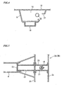
FIG. 7A is a schematic view showing an image of load transmission of a rear frame of a comparative example, whileFIG. 7B is a schematic view showing an image of load transmission of a rear frame of the embodiment. - An embodiment of the present invention is described below based on the drawings. Note that in the description given below, unless specifically stated otherwise, 'up', 'down', 'left', and 'right' refer to the up, down, left, and right with respect to a vehicle 1 facing in a forward direction, respectively. In addition, the arrow F in the drawings points towards the front of the vehicle, while the arrow U points towards the top of the vehicle.
-
FIG. 1 shows a sedan vehicle 1 which employs the vehicle rear portion structure according to the embodiment of the present invention, and shows a rear portion of the longitudinally sliced vehicle 1 as seen from a diagonally forward and upward direction.FIGS. 2 and3 are views respectively from a direction of the arrows A and B inFIG. 1 . Note that floor panels such as a spare tire panel have been omitted from these drawings. - As is shown in
FIGS. 1 through 3 , a pair ofrear frames rear frames middle cross member 3 and arear cross member 4 respectively. Front edge portions of the tworear frames side sills rear wheel houses rear wheel houses rear frame - Moreover, a
rear parcel shelf 7 that substantially vertically divides the passenger compartment from the trunk space is provided in a position on the rear side of the rear seat (not shown). On a front end portion side of thisrear parcel shelf 7, there is provided aparcel frame 8 that has a rectangular cross section and extends substantially in the vehicle width direction. The two end portions of thisparcel frame 8 are supported respectively by therear wheel houses side panel inners 10 that form side walls of the inner side of the vehicle body. - Moreover, as is shown in
FIG. 1 , a double wishbone type of suspension that supports anindependent damper 12 and aspring 13 at separate positions is used for arear suspension 11 of this vehicle 1. Distal end portions oflower arms 14 of the respective left and rightrear suspensions 11 are oscillatingly supported onarm supporting portions 15 that are provided on an inner side in the vehicle width direction of therear cross member 4. Moreover, top end portions of thedampers 12 of the respectiverear suspensions 11 are mounted ondamper supporting portions 16 on apex portions of therear wheel houses springs 13 of the respectiverear suspensions 11 are mounted onspring supporting portions 17 on bottom surfaces of therear frames spring supporting portions 17 are each provided in the vicinity of the respective joint portions of therear cross member 4. - Wheel house frames 18 (i.e., reinforcing components) that have a substantially a U-shaped cross section and extend in a vertical direction are each joined to side surfaces of the left and right
rear wheel houses damper supporting portions 16. Top and bottom ends of the respective wheel house frames 18 are joined to respective end portions of theparcel frame 8 and therear cross member 4. As is described above, end portions on both sides of theparcel frame 8 and therear cross member 4 are connected to each other with the wheel house frames 18 and 18 resulting in theparcel frame 8 and therear cross member 4 forming a toroidal skeleton frame together with the wheel house frames 18 and 18. Moreover, theparcel frame 8 is placed at a position directly above therear cross member 4 so that, as a result, the entire toroidal skeleton frame is located within a plane which is orthogonal to the longitudinal direction of the vehicle. - As is shown in
FIG 2 , top end portions of eachwheel house frame 18 are made to abut against a bottom surface of theparcel frame 8 so as to form substantially T-shaped structures together with the respective edges thereof, and are joined to theparcel frame 8. The aforementioned damper base covers 9 (i.e., reinforcing components) that cover the top of the damper supporting portions 16 (seeFIG. 1 ) which are on the apex portions of therear wheel houses rear wheel houses parcel frame 8 that protrude onto the outer side in the vehicle width direction beyond the wheel house frames 18. - Each
damper base cover 9 is formed having substantially a U-shaped cross section as is shown in the cross-sectional view ofFIG. 4 , and the open sides of the U shape are connected to the side panel inner 10 so as to cover an area surrounding the top of thedamper supporting portion 16. Accordingly, thedamper base cover 9 together with the side panel inner 10 forms a rectangular, closed section structure. Furthermore, bottom end portions of the damper base covers 9 are connected to an apex portion of therear wheel house 6A (or 6B) so as to cover thedamper supporting portion 16, while, in contrast, top end portions of the damper base covers 9 are connected to an edge of theparcel frame 8. A side surface on the inner side in the vehicle width direction of thedamper base cover 9 is connected to a top edge portion of thewheel house frame 18 that protrudes upwards from therear wheel house 6A (or 6B). Accordingly, thedamper base cover 9 which has a closed section structure reinforces the area surrounding thedamper supporting portion 16, and also reinforces the joint portion between theparcel frame 8 and thewheel house frame 18. - Note that as is shown in
FIG 4 , in order to allow anadjustment nut 32 of thedamper 12 to be operated, a workinghole 31 is formed in a side wall of thedamper base cover 9. - As is shown in
FIG. 3 , concave portions having substantially a U-shaped cross section that is open in an upward direction are formed in therear frames rear cross member 4, and a floor panel 30 (seeFIG. 6 ) is joined toflanges rear cross member 4 are joined in a state of abutting against vehicleinner side walls 2b of therear frames - A bottom end of the
wheel house frame 18 is inserted into a part of the concave portion of therear frame 2A (or 2B), where thecross member 4 is connected, and this bottom end of thewheel house frame 18 is joined to the vehicleouter side wall 2c. Note that the width of the concave portion of therear frame 2A (or 2B) at this part is formed larger than the width of the bottom end of thewheel house frame 18 in the vehicle width direction. Because of this, there is a gap between the bottom end of thewheel house frame 18 and the vehicleinner side wall 2b of therear frame 2A (or 2B), and, as is shown in the cross-sectional view shown inFIG. 5 , a first bulkhead 20 (i.e., an internal reinforcing component) which has substantially a U-shaped cross section is housed in this gap. Thisfirst bulkhead 20 is joined to the vehicleinner side wall 2b. In the case of the present embodiment, thefirst bulkhead 20 is further joined to the bottom end of thewheel house frame 18 with abolt 21, so as to be integral with thewheel house frame 18. - Moreover, as is shown in cross-sectional view in
FIG. 6 , a second bulkhead 22 (i.e., an internal reinforcing component) which has substantially a U-shaped cross section that is open at the bottom and extends from the vehicleinner side wall 2b of therear frame 2A (or 2B) towards the inner side in the vehicle width direction is joined to a bottom portion of the concave portion in therear cross member 4. One end portion of thissecond bulkhead 22 is closed off by a planar third bulkhead 23 (i.e., an internal reinforcing component), and circumferential edge portions of thisthird bulkhead 23 are joined to an internal surface of the concave portion in therear cross member 4. - The aforementioned first, second, and
third bulkheads rear frame 2A (or 2B) and therear cross member 4, and form a cross section that is continuous from thewheel house frame 18 to therear cross member 4. Namely, the horizontal cross section of thewheel house frame 18, and vertical cross sections of the first, second, andthird bulkheads - As has been described above, in this vehicle rear portion structure of the vehicle 1, the toroidal skeleton frame that is created by mutually connecting together the two end portions of the
parcel frame 8 and therear cross member 4 with the wheel house frames 18 and 18 is placed between the side portions of therear wheel houses arm supporting portions 15, thedamper supporting portions 16, and thespring supporting portions 17, which are mounting points for therear suspension 11, are provided along this toroidal skeleton frame. Because of this, it is possible to increase the torsional rigidity of the vehicle body by means of this toroidal skeleton frame, and load input from therear suspension 11 is directly received by the toroidal skeleton frame. As a result, it is possible for the properties of therear suspension 11 to be demonstrated to their maximum potential. Namely, the loads that are input from thearm supporting portion 15, thedamper supporting portion 16, and thespring supporting portion 17 can be rigidly supported within the same plane by the toroidal skeleton frame. Because of this, it is possible to eliminate any variation in the timing of the load inputs at each of the supportingpoints - Accordingly, in the case where this vehicle rear portion structure is being employed, it is possible to efficiently improve the support rigidity of the
rear suspension 11 without adding any heavy reinforcing components. As a result, it is possible to achieve both an improvement in rigidity and a reduction in weight. - Moreover, in this vehicle rear portion structure, substantially a center position of the left and right
rear frames rear frames rear frames - Namely, if there is no toroidal skeleton frame, as is shown in
FIG. 7A , a load RF that is input into a rear portion of therear frames rear frames FIG. 7B , since a portion of the load RF is dispersed in eachwheel house frame 18 at substantially a central position between therear frames rear frames - Moreover, in this vehicle rear portion structure, top end portions of wheel house frames 18 are abutted against and joined to the
parcel frame 8 so as to form what is substantially a T shape with the respective edges of theparcel frame 8. Moreover, thedamper base cover 9 is provided in each of the spaces that are formed between therear wheel houses parcel frame 8 which protrudes towards the outer side of the vehicle from eachwheel house frame 18. Eachdamper base cover 9 is connected to the respective edges of theparcel frame 8 and each of the top edge portions of the wheel house frames 18. Because of this, it is possible to rigidly connect theparcel frame 8 to thewheel house frame 18 while suppressing any buckling into the passenger compartment. - Furthermore, in this vehicle rear portion structure, the bottom end of each
wheel house frame 18 is joined to the inside of concave portions of therear frames first bulkheads 20 that have a U-shaped cross section are each joined between the bottom end of eachwheel house frame 18 inside the concave portion and the vehicleinner side wall 2b of the respectiverear frames second bulkhead 22 and thethird bulkhead 23 are joined inside the concave portion, which has substantially a U-shaped cross section, of each end of therear cross member 4 so as to be continuous with the cross section of thefirst bulkhead 20 sandwiching each vehicleinner side wall 2b. As a result, in the interior portions of therear frames rear cross member 4, it is possible to rigidly connect together the three components of thewheel house frame 18, therear frames rear cross member 4 so as to form a continuous cross section. Accordingly, in these portions as well, it is possible to increase the rigidity of the joint portions while suppressing any buckling into the passenger compartment. - In the vehicle rear portion structure of this embodiment, because it is possible to sufficiently suppress the amount of buckling into the passenger compartment of the toroidal skeleton frame, as is described above, when an open portion is secured below the
parcel frame 8 so as to form what is known as a trunk through structure, the advantage is obtained that it is possible to secure a sufficiently large width for this open space. - A vehicle rear portion structure including: a pair of rear frames that extend substantially in a vehicle longitudinal direction; a rear cross member that extends in a vehicle width direction and that connects both of the two rear frames; a pair of rear wheel houses that are provided with damper supporting portions; a parcel frame that extends along the vehicle width direction above the rear wheel houses; and a pair of reinforcing frames that connect both end portions of the rear cross member and both end portions of the parcel frame, wherein the reinforcing frames are placed along a side wall of respective the rear wheel houses, the side wall being adjacent to respective the damper supporting portions, and a toroidal skeleton frame is formed with the parcel frame, the reinforcing frames, and the rear cross member so as to follow a plurality of rear suspension mounting points.
Claims (6)
- A vehicle rear portion structure comprising:a pair of rear frames (2A, 2B) that extend substantially in a vehicle longitudinal direction;a rear cross member (4) that extends in a vehicle width direction and that connects both of the two rear frames (2A, 2B);a pair of rear wheel houses (6A, 6B) that cover top half portions of both left and right rear wheels, and that are provided with damper supporting portions (16) placed in the vicinity of the apex portions of the rear wheel houses (6A, 6B) for supporting dampers (12) of rear suspensions (11);a parcel frame (8) that forms a skeleton of a rear parcel shelf (7), and extends along the vehicle width direction above the rear wheel houses (6A, 6B); anda pair of reinforcing frames (18) that connect both end portions of the rear cross member (4) and both end portions of the parcel frame (8), wherein the reinforcing frames (18) are placed along a side wall of respective said rear wheel houses (6A, 6B), the side wall being adjacent to respective said damper supporting portions (16), anda toroidal skeleton frame is formed with the parcel frame (8), the reinforcing frames (18), and the rear cross member (4) so as to follow a plurality of rear suspension mounting points (15, 16, 17) that include the damper supporting portions (16);wherein the rear frames (2A, 2B) and both ends of the rear cross member (4) are provided with concave portions that have substantially a U-shaped cross section with an upper side thereof being open, in at least the vicinity of respective joint portions between the respective rear frame members (2A, 28) and the rear cross member (4);characterized in thatbottom ends of the respective reinforcing frames (18) are inserted in and connected to the concave portions of the respective rear frames (2A, 2B); andthe vehicle rear portion structure further comprises an internal reinforcing component (22, 23) of which a vertical cross section parallel to the rear frames (2A, 2B) is substantially the same shape as a horizontal cross section of each of the reinforcing frames (18), and which connects the bottom ends of the respective reinforcing frames (18), the concave portions of the respective rear frames (2A, 2B), and the respective concave portions in the rear cross member (4).
- The vehicle rear portion structure according to claim 1, wherein the vehicle rear portion structure further comprises reinforcing components (9) that have a closed section structure, and that cover a top portion of respective said damper supporting portions (16);
top end portions of the refraining frames (18) are connected to the parcel frame (8) so as to form substantially T-shapes with respective edges thereof; and
wherein the reinforcing components (9) are connected to respective said edges of the parcel frame (8) and respective top edge portions of the reinforcing frames (9). - The vehicle rear portion structure according to claim 1, comprising: first internal reinforcing components (20) that are connected to respective said bottom end of the reinforcing frames (18), and are each placed between the reinforcing frame (18) and the rear cross member (4) inside the concave portion of the rear frame (4); and second internal reinforcing components (22) that are each placed inside respective said concave portions of the rear cross members (4);
the first internal reinforcing components (20)and the second internal reinforcing components (22) have a vertical cross section parallel with the rear frame (2A, 2B), the vertical section having substantially the same shape as the horizontal cross section of the reinforcing frames (18); and the first internal reinforcing components (20) and the second internal reinforcing components (22) are connected via the respective rear frames (2A, 2B). - The vehicle rear portion structure according to claim 3, wherein the first internal reinforcing components (20) have a U shape that is open on the rear cross member (4) side thereof.
- The vehicle rear portion structure according to claim 3, wherein the second internal reinforcing components (22) have a U shape that is open on the bottom side thereof.
- The vehicle rear portion structure according to claim 1, wherein the toroidal skeleton frame further follows arm supporting portions (15) for oscillatingly supporting lower arms (14) of the respective rear suspension (11) and further follows spring supporting portions (17) supporting top end portion of springs (13) of the respective rear suspensions (11),
wherein the arm supporting portions (15) are provided on an inner side in the vehicle width direction of the rear cross member (4) and the spring supporting portions (17) are provided on bottom surfaces of the respctive rear frames (2A, 2B).
Applications Claiming Priority (1)
| Application Number | Priority Date | Filing Date | Title |
|---|---|---|---|
| JP2007126101A JP4956268B2 (en) | 2007-05-10 | 2007-05-10 | Car body rear structure |
Publications (3)
| Publication Number | Publication Date |
|---|---|
| EP1990262A1 EP1990262A1 (en) | 2008-11-12 |
| EP1990262A8 EP1990262A8 (en) | 2009-01-07 |
| EP1990262B1 true EP1990262B1 (en) | 2009-09-09 |
Family
ID=39495497
Family Applications (1)
| Application Number | Title | Priority Date | Filing Date |
|---|---|---|---|
| EP08008684A Expired - Fee Related EP1990262B1 (en) | 2007-05-10 | 2008-05-08 | Vehicle rear portion structure |
Country Status (4)
| Country | Link |
|---|---|
| US (1) | US7758108B2 (en) |
| EP (1) | EP1990262B1 (en) |
| JP (1) | JP4956268B2 (en) |
| DE (1) | DE602008000135D1 (en) |
Families Citing this family (12)
| Publication number | Priority date | Publication date | Assignee | Title |
|---|---|---|---|---|
| US9308013B2 (en) | 2010-11-03 | 2016-04-12 | Gyrus Ent, L.L.C. | Surgical tool with sheath |
| JP5429246B2 (en) * | 2011-08-10 | 2014-02-26 | トヨタ自動車株式会社 | Car body rear structure |
| WO2015068549A1 (en) * | 2013-11-11 | 2015-05-14 | 本田技研工業株式会社 | Vehicle body structure |
| JP6136983B2 (en) * | 2014-02-27 | 2017-05-31 | マツダ株式会社 | Rear structure of the vehicle |
| JP6358014B2 (en) * | 2014-09-26 | 2018-07-18 | スズキ株式会社 | Vehicle rear structure |
| JP6156356B2 (en) * | 2014-12-25 | 2017-07-05 | トヨタ自動車株式会社 | Vehicle rear structure |
| CN104670335A (en) * | 2015-03-17 | 2015-06-03 | 安徽江淮汽车股份有限公司 | Automobile body and automobile |
| JP6517590B2 (en) * | 2015-06-01 | 2019-05-22 | 本田技研工業株式会社 | Rear body structure |
| DE102018001534A1 (en) * | 2017-03-27 | 2018-09-27 | Mazda Motor Corporation | Rear vehicle body structure for a vehicle |
| JP2019162997A (en) * | 2018-03-20 | 2019-09-26 | マツダ株式会社 | Rear vehicle body structure |
| WO2020164033A1 (en) * | 2019-02-14 | 2020-08-20 | Psa Automobiles Sa | Bracket element attaching wheel housing to the rear parcel shelf |
| WO2020261917A1 (en) * | 2019-06-27 | 2020-12-30 | 本田技研工業株式会社 | Vehicle rear structure |
Family Cites Families (10)
| Publication number | Priority date | Publication date | Assignee | Title |
|---|---|---|---|---|
| DE3423573A1 (en) * | 1984-06-27 | 1986-01-09 | Elektroschmelzwerk Kempten GmbH, 8000 München | POLYCRYSTALLINE SINTER BODIES BASED ON SILICON NITRIDE AND SINTER ADDITIVES |
| JPH0628417B2 (en) * | 1985-01-14 | 1994-04-13 | 松下電器産業株式会社 | Multi-channel TV receiver |
| JPH01145677A (en) * | 1987-12-01 | 1989-06-07 | Minolta Camera Co Ltd | Developing device |
| JP2800153B2 (en) * | 1989-05-31 | 1998-09-21 | 株式会社リコー | Liquid developer for electrostatic photography |
| JPH0326677A (en) * | 1989-06-23 | 1991-02-05 | Mitsubishi Electric Corp | Riding spot device for temporary elevator |
| JPH0589164U (en) * | 1992-05-08 | 1993-12-03 | マツダ株式会社 | Rear body structure of automobile |
| US5580121A (en) * | 1995-12-19 | 1996-12-03 | Chrysler Corporation | Vehicle body rear support arrangement |
| US6113180A (en) * | 1997-09-25 | 2000-09-05 | Chrysler Corporation | Closed loop vehicle frame structure for laterally spaced suspension components |
| SE9901260L (en) * | 1999-04-09 | 2000-10-10 | Volvo Personvagnar Ab | Beam knot included in a body structure |
| JP4277215B2 (en) * | 2004-12-13 | 2009-06-10 | 関東自動車工業株式会社 | Rear body structure of the vehicle |
-
2007
- 2007-05-10 JP JP2007126101A patent/JP4956268B2/en not_active Expired - Fee Related
-
2008
- 2008-05-01 US US12/113,560 patent/US7758108B2/en not_active Expired - Fee Related
- 2008-05-08 DE DE602008000135T patent/DE602008000135D1/en active Active
- 2008-05-08 EP EP08008684A patent/EP1990262B1/en not_active Expired - Fee Related
Also Published As
| Publication number | Publication date |
|---|---|
| JP4956268B2 (en) | 2012-06-20 |
| US20080277970A1 (en) | 2008-11-13 |
| JP2008279906A (en) | 2008-11-20 |
| US7758108B2 (en) | 2010-07-20 |
| EP1990262A8 (en) | 2009-01-07 |
| EP1990262A1 (en) | 2008-11-12 |
| DE602008000135D1 (en) | 2009-10-22 |
Similar Documents
| Publication | Publication Date | Title |
|---|---|---|
| EP1990262B1 (en) | Vehicle rear portion structure | |
| US7364225B2 (en) | Vehicle body structure | |
| US7281756B2 (en) | Automotive rear body structure | |
| JP4424208B2 (en) | Body front structure | |
| EP1400437B1 (en) | Front structure of vehicle | |
| CN101585331B (en) | Frame structure of seat back for vehicle and seat back for vehicle with frame structure | |
| JP4774976B2 (en) | Rear body structure of the vehicle | |
| US9873458B2 (en) | Vehicle rear structure | |
| JPH08216927A (en) | Car body rear structure | |
| RU2550401C2 (en) | Car body structure | |
| US20120119542A1 (en) | Car body with reinforcing structure | |
| JP7013995B2 (en) | Vehicle front body structure | |
| EP2058212B1 (en) | Vehicle equipped with passenger frame having small height from ground | |
| JP5493971B2 (en) | Rear body structure of the vehicle | |
| JP4923406B2 (en) | Body front structure | |
| EP0980817A2 (en) | Method for manufacturing a rear structure for a motor vehicle | |
| JP4335841B2 (en) | Rear body structure of hatchback type vehicle | |
| JP4315929B2 (en) | Auto body structure | |
| EP3632779B1 (en) | Front vehicle body structure for vehicle | |
| JP6977578B2 (en) | Rear body structure of the vehicle | |
| JP2006273134A (en) | Vehicular rear part structure | |
| JP6973104B2 (en) | Rear body structure of the vehicle | |
| US9738326B2 (en) | Structure of rear package tray | |
| CN219154587U (en) | Vehicle rear side wall structure and vehicle | |
| JPH11192977A (en) | Body frame reinforcing structure for automobile |
Legal Events
| Date | Code | Title | Description |
|---|---|---|---|
| PUAI | Public reference made under article 153(3) epc to a published international application that has entered the european phase |
Free format text: ORIGINAL CODE: 0009012 |
|
| 17P | Request for examination filed |
Effective date: 20080508 |
|
| AK | Designated contracting states |
Kind code of ref document: A1 Designated state(s): AT BE BG CH CY CZ DE DK EE ES FI FR GB GR HR HU IE IS IT LI LT LU LV MC MT NL NO PL PT RO SE SI SK TR |
|
| AX | Request for extension of the european patent |
Extension state: AL BA MK RS |
|
| RIN1 | Information on inventor provided before grant (corrected) |
Inventor name: EGAWA, YASUHISA C/O HONDA R&D CO., LTD. Inventor name: YASUHARA, SHIGETO C/O HONDA R&D CO., LTD. Inventor name: MATSUURA, YUJIC/O PSG CO., LTD. Inventor name: OKANO, TOMOHIKOC/O MEITEC CORPORATION |
|
| GRAP | Despatch of communication of intention to grant a patent |
Free format text: ORIGINAL CODE: EPIDOSNIGR1 |
|
| GRAS | Grant fee paid |
Free format text: ORIGINAL CODE: EPIDOSNIGR3 |
|
| AKX | Designation fees paid |
Designated state(s): DE GB |
|
| GRAA | (expected) grant |
Free format text: ORIGINAL CODE: 0009210 |
|
| AK | Designated contracting states |
Kind code of ref document: B1 Designated state(s): DE GB |
|
| REG | Reference to a national code |
Ref country code: GB Ref legal event code: FG4D |
|
| REF | Corresponds to: |
Ref document number: 602008000135 Country of ref document: DE Date of ref document: 20091022 Kind code of ref document: P |
|
| PLBE | No opposition filed within time limit |
Free format text: ORIGINAL CODE: 0009261 |
|
| STAA | Information on the status of an ep patent application or granted ep patent |
Free format text: STATUS: NO OPPOSITION FILED WITHIN TIME LIMIT |
|
| 26N | No opposition filed |
Effective date: 20100610 |
|
| PGFP | Annual fee paid to national office [announced via postgrant information from national office to epo] |
Ref country code: DE Payment date: 20100512 Year of fee payment: 3 |
|
| REG | Reference to a national code |
Ref country code: DE Ref legal event code: R119 Ref document number: 602008000135 Country of ref document: DE Effective date: 20111201 |
|
| PGFP | Annual fee paid to national office [announced via postgrant information from national office to epo] |
Ref country code: GB Payment date: 20120502 Year of fee payment: 5 |
|
| PG25 | Lapsed in a contracting state [announced via postgrant information from national office to epo] |
Ref country code: DE Free format text: LAPSE BECAUSE OF NON-PAYMENT OF DUE FEES Effective date: 20111201 |
|
| GBPC | Gb: european patent ceased through non-payment of renewal fee |
Effective date: 20130508 |
|
| PG25 | Lapsed in a contracting state [announced via postgrant information from national office to epo] |
Ref country code: GB Free format text: LAPSE BECAUSE OF NON-PAYMENT OF DUE FEES Effective date: 20130508 |