EP1990249A2 - Récipient sous pression destiné à être monté dans un véhicule - Google Patents
Récipient sous pression destiné à être monté dans un véhicule Download PDFInfo
- Publication number
- EP1990249A2 EP1990249A2 EP08450069A EP08450069A EP1990249A2 EP 1990249 A2 EP1990249 A2 EP 1990249A2 EP 08450069 A EP08450069 A EP 08450069A EP 08450069 A EP08450069 A EP 08450069A EP 1990249 A2 EP1990249 A2 EP 1990249A2
- Authority
- EP
- European Patent Office
- Prior art keywords
- pressure vessel
- clamping elements
- vessel according
- jacket
- clamping element
- Prior art date
- Legal status (The legal status is an assumption and is not a legal conclusion. Google has not performed a legal analysis and makes no representation as to the accuracy of the status listed.)
- Withdrawn
Links
Images

Classifications
-
- B—PERFORMING OPERATIONS; TRANSPORTING
- B60—VEHICLES IN GENERAL
- B60T—VEHICLE BRAKE CONTROL SYSTEMS OR PARTS THEREOF; BRAKE CONTROL SYSTEMS OR PARTS THEREOF, IN GENERAL; ARRANGEMENT OF BRAKING ELEMENTS ON VEHICLES IN GENERAL; PORTABLE DEVICES FOR PREVENTING UNWANTED MOVEMENT OF VEHICLES; VEHICLE MODIFICATIONS TO FACILITATE COOLING OF BRAKES
- B60T17/00—Component parts, details, or accessories of power brake systems not covered by groups B60T8/00, B60T13/00 or B60T15/00, or presenting other characteristic features
- B60T17/06—Applications or arrangements of reservoirs
Definitions
- the present invention relates to a pressure vessel for mounting on a vehicle, in particular compressed air tank for compressed air brakes, with a sheath in the form of a flat pillow whose flat sides are clamped against each other by means of at least one clamping element passing through the container interior.
- Compressed air tanks for vehicles are usually designed in the form of cylinders with dome-shaped end faces in order to withstand the highest possible internal pressures.
- this design has the disadvantage that the usually parallelepipedic available installation space can not be optimally utilized.
- a flat compressed air tank which is assembled from a plurality of parallel pipe segments, between which run partitions separating walls, which connect the flat sides of the container together.
- the partitions mean a high material consumption, increased weight and require many long connecting seams during production.
- the invention sets itself the goal of creating a pressure vessel with optimized space requirements, which overcomes the disadvantages mentioned.
- This object is achieved with a pressure vessel of the type mentioned, which is characterized according to the invention in that said at least one clamping element has an elongated shape in the direction normal to the flat sides.
- the pressure vessel according to the invention provides with a minimum consumption of material with the same installation space requirement a larger internal volume than, for example, groups of conventional cylindrical containers, while its clamping elements ensure comparably high internal pressures.
- the clamping elements are tubular, which ensures particularly high stability with reduced weight.
- the tension members may be band or bar shaped to minimize material consumption and maximize the useful interior volume.
- the clamping elements can engage in any manner on the jacket or be connected to this, for example by screwing, soldering, gluing, etc. More preferably, the clamping elements are welded to the shell, whereby high strength can be achieved with ease of installation.
- the jacket and the clamping elements can be made of plastic, for example; they are preferably made of metal, which combines high strength with low weight.
- jacket and the clamping elements are made of thin-walled aluminum sheet, which results in a lightweight, thin-walled cushion, which is held by the internal pressure and its inner clamping elements in shape is particularly advantageous.
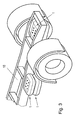
- Fig. 1 and 2 has a pressure vessel 1 a sheath 2 in the form of a flat pillow with - seen from above - approximately rounded-rectangular circumference 3.
- the flat sides 4, 5 of the shell 2 are stretched by means of six the container interior 6 passing through clamping elements 7 against each other.
- the number of clamping elements 7 is variable and is preferred accordingly the container size chosen to ensure said flat pillow shape; For small containers, for example, only a single clamping element 7 can be used.
- the clamping elements 7 have - as shown - an elongated in the direction normal to the flat sides 4, 5 and are preferably tubular, e.g. produced by extrusion.
- the tube ends 8 of the clamping elements 7 are glued to the container casing 2 over its circumference, soldered, screwed, etc., preferably welded.
- cover caps 9 may be inserted into the tube ends 8 in order to increase the dimensional stability of the clamping elements 7.
- clamping elements 7 may have any other cross-sectional shape, for example band or bar shape,
- the pressure vessel 1, i. its jacket 2, the clamping elements 7 and the cover caps 9 may be made of plastic or preferably metal, particularly preferably thin-walled aluminum sheet.
- Fig. 3 shows the practical use of two pairs of each stacked pillow-shaped pressure vessels 1 in a partially illustrated vehicle frame 10. As can be seen, results with the help of the presented pressure vessel 1 optimum utilization of available in the vehicle frame parallelepipedic installation space.
Landscapes
- Engineering & Computer Science (AREA)
- Transportation (AREA)
- Mechanical Engineering (AREA)
- Filling Or Discharging Of Gas Storage Vessels (AREA)
- Valves And Accessory Devices For Braking Systems (AREA)
- Cooling, Air Intake And Gas Exhaust, And Fuel Tank Arrangements In Propulsion Units (AREA)
- Pressure Vessels And Lids Thereof (AREA)
Applications Claiming Priority (1)
| Application Number | Priority Date | Filing Date | Title |
|---|---|---|---|
| AT0029107U AT10161U1 (de) | 2007-05-10 | 2007-05-10 | Druckbehälter zur montage an einem fahrzeug |
Publications (2)
| Publication Number | Publication Date |
|---|---|
| EP1990249A2 true EP1990249A2 (fr) | 2008-11-12 |
| EP1990249A3 EP1990249A3 (fr) | 2009-07-01 |
Family
ID=39708543
Family Applications (1)
| Application Number | Title | Priority Date | Filing Date |
|---|---|---|---|
| EP08450069A Withdrawn EP1990249A3 (fr) | 2007-05-10 | 2008-05-06 | Récipient sous pression destiné à être monté dans un véhicule |
Country Status (2)
| Country | Link |
|---|---|
| EP (1) | EP1990249A3 (fr) |
| AT (1) | AT10161U1 (fr) |
Cited By (1)
| Publication number | Priority date | Publication date | Assignee | Title |
|---|---|---|---|---|
| DE102022116293A1 (de) | 2022-06-30 | 2024-01-04 | Dr. Ing. H.C. F. Porsche Aktiengesellschaft | Druckspeicher |
Citations (1)
| Publication number | Priority date | Publication date | Assignee | Title |
|---|---|---|---|---|
| JP2005015576A (ja) | 2003-06-25 | 2005-01-20 | Nisshinbo Ind Inc | 摩擦材 |
Family Cites Families (5)
| Publication number | Priority date | Publication date | Assignee | Title |
|---|---|---|---|---|
| US5307836A (en) * | 1992-09-25 | 1994-05-03 | Ventra Corporation | Vehicle multi-compartment air-brake reservoir with internal check valve |
| US6056007A (en) * | 1997-07-15 | 2000-05-02 | Q3 JMC, Inc. | Air tank manifold |
| AT2594U1 (de) * | 1997-12-15 | 1999-01-25 | Alutech Gmbh | Vorrichtung zur montage von druckluftbehältern an einem fahrzeugrahmen |
| US6601926B2 (en) * | 2001-08-21 | 2003-08-05 | Caterpillar Inc | Air reservoir for air brake system |
| DE10226530A1 (de) * | 2002-06-14 | 2003-12-24 | Daimler Chrysler Ag | Mehrkammerdruckbehälter |
-
2007
- 2007-05-10 AT AT0029107U patent/AT10161U1/de not_active IP Right Cessation
-
2008
- 2008-05-06 EP EP08450069A patent/EP1990249A3/fr not_active Withdrawn
Patent Citations (1)
| Publication number | Priority date | Publication date | Assignee | Title |
|---|---|---|---|---|
| JP2005015576A (ja) | 2003-06-25 | 2005-01-20 | Nisshinbo Ind Inc | 摩擦材 |
Cited By (1)
| Publication number | Priority date | Publication date | Assignee | Title |
|---|---|---|---|---|
| DE102022116293A1 (de) | 2022-06-30 | 2024-01-04 | Dr. Ing. H.C. F. Porsche Aktiengesellschaft | Druckspeicher |
Also Published As
| Publication number | Publication date |
|---|---|
| EP1990249A3 (fr) | 2009-07-01 |
| AT10161U1 (de) | 2008-10-15 |
Similar Documents
| Publication | Publication Date | Title |
|---|---|---|
| DE102005026376C5 (de) | Fahrzeugschalldämpfer | |
| DE602004002122T2 (de) | Doppelrohr und Verfahren zu dessen Herstellung | |
| DE102018119087A1 (de) | Fahrzeugunterteilaufbau | |
| EP3610478B1 (fr) | Actionneur de bruit solidien pour véhicule automobile et véhicule automobile | |
| DE102008064002A1 (de) | Unterwasserantenne | |
| DE102012204059B3 (de) | Schockdämpfer für die Lagerung eines Gegenstandes in oder an einem Fahrzeug | |
| DE2357673C3 (de) | Vorrichung zum Abtrennen einer Flüssigkeit aus einem diese Flüssigkeit enthaltenden Gemisch mittels umgekehrter Osmose | |
| EP2202412B1 (fr) | Accumulateur hydraulique | |
| DE102009033804A1 (de) | Befestigungsvorrichtung für die Befestigung von Solarpaneelen an einer Montageschiene | |
| DE102007040416B4 (de) | Kraftstoffbehälter für Nutzfahrzeuge | |
| EP1990249A2 (fr) | Récipient sous pression destiné à être monté dans un véhicule | |
| DE102010014497B4 (de) | Kraftstoffverteileinrichtung für ein Kraftfahrzeug, Kraftfahrzeug und Verfahren zum Fertigen einer Kraftstoffverteileinrichtung | |
| DE102010007980A1 (de) | Vorrichtung zur Kompression einer Brennstoffzellenanordnung | |
| DE102009050588A1 (de) | Befestigungssystem für Körper, insbesondere von solchen mit einem runden Umfangbereich wie Behälter oder Rohre | |
| DE102010015469A1 (de) | Federstruktur aus mehreren Federelementen | |
| EP2121212B1 (fr) | Ressort de compression à deux ou plus de deux couches | |
| WO2007079761A1 (fr) | Conduite souple pour fluide et son procédé de fabrication | |
| DE102014204259A1 (de) | Verfahren und Vorrichtung zum Herstellen eines Wärmetauschers | |
| DE102007027706A1 (de) | Wärmetauscher | |
| DE102005033848A1 (de) | Federspeicher-Bremszylinder | |
| DE102017002211A1 (de) | Abstandselement zur Verwendung in einer Halteanordnung, Halteanordnung und diese Halteanordnung umfassendes Fahrzeug | |
| DE102019207799A1 (de) | Tauchrohr zur Kältemittelverteilung in einem Chiller | |
| DE102010054232A1 (de) | Anordnung eines Druckbehälters an einem Fahrzeug | |
| DE69814243T2 (de) | Flexibles, gewelltes Rohr zum Entkuppeln von Fahrzeugmotorabgasleitungen | |
| DE112008001511T5 (de) | Schalldämpfer für eine Auspuffleitung eines Kraftfahrzeugs |
Legal Events
| Date | Code | Title | Description |
|---|---|---|---|
| PUAI | Public reference made under article 153(3) epc to a published international application that has entered the european phase |
Free format text: ORIGINAL CODE: 0009012 |
|
| AK | Designated contracting states |
Kind code of ref document: A2 Designated state(s): AT BE BG CH CY CZ DE DK EE ES FI FR GB GR HR HU IE IS IT LI LT LU LV MC MT NL NO PL PT RO SE SI SK TR |
|
| AX | Request for extension of the european patent |
Extension state: AL BA MK RS |
|
| PUAL | Search report despatched |
Free format text: ORIGINAL CODE: 0009013 |
|
| AK | Designated contracting states |
Kind code of ref document: A3 Designated state(s): AT BE BG CH CY CZ DE DK EE ES FI FR GB GR HR HU IE IS IT LI LT LU LV MC MT NL NO PL PT RO SE SI SK TR |
|
| AX | Request for extension of the european patent |
Extension state: AL BA MK RS |
|
| AKX | Designation fees paid | ||
| REG | Reference to a national code |
Ref country code: DE Ref legal event code: 8566 |
|
| STAA | Information on the status of an ep patent application or granted ep patent |
Free format text: STATUS: THE APPLICATION IS DEEMED TO BE WITHDRAWN |
|
| 18D | Application deemed to be withdrawn |
Effective date: 20100105 |