EP1990210B2 - Surfaces structurées qui exposent des couleurs par rotation - Google Patents
Surfaces structurées qui exposent des couleurs par rotation Download PDFInfo
- Publication number
- EP1990210B2 EP1990210B2 EP08155661.5A EP08155661A EP1990210B2 EP 1990210 B2 EP1990210 B2 EP 1990210B2 EP 08155661 A EP08155661 A EP 08155661A EP 1990210 B2 EP1990210 B2 EP 1990210B2
- Authority
- EP
- European Patent Office
- Prior art keywords
- structures
- optically variable
- pyramidal
- color
- pyramids
- Prior art date
- Legal status (The legal status is an assumption and is not a legal conclusion. Google has not performed a legal analysis and makes no representation as to the accuracy of the status listed.)
- Active
Links
Images


Classifications
-
- G—PHYSICS
- G02—OPTICS
- G02B—OPTICAL ELEMENTS, SYSTEMS OR APPARATUS
- G02B5/00—Optical elements other than lenses
- G02B5/18—Diffraction gratings
- G02B5/1814—Diffraction gratings structurally combined with one or more further optical elements, e.g. lenses, mirrors, prisms or other diffraction gratings
-
- B—PERFORMING OPERATIONS; TRANSPORTING
- B42—BOOKBINDING; ALBUMS; FILES; SPECIAL PRINTED MATTER
- B42D—BOOKS; BOOK COVERS; LOOSE LEAVES; PRINTED MATTER CHARACTERISED BY IDENTIFICATION OR SECURITY FEATURES; PRINTED MATTER OF SPECIAL FORMAT OR STYLE NOT OTHERWISE PROVIDED FOR; DEVICES FOR USE THEREWITH AND NOT OTHERWISE PROVIDED FOR; MOVABLE-STRIP WRITING OR READING APPARATUS
- B42D25/00—Information-bearing cards or sheet-like structures characterised by identification or security features; Manufacture thereof
- B42D25/30—Identification or security features, e.g. for preventing forgery
- B42D25/324—Reliefs
-
- B—PERFORMING OPERATIONS; TRANSPORTING
- B42—BOOKBINDING; ALBUMS; FILES; SPECIAL PRINTED MATTER
- B42D—BOOKS; BOOK COVERS; LOOSE LEAVES; PRINTED MATTER CHARACTERISED BY IDENTIFICATION OR SECURITY FEATURES; PRINTED MATTER OF SPECIAL FORMAT OR STYLE NOT OTHERWISE PROVIDED FOR; DEVICES FOR USE THEREWITH AND NOT OTHERWISE PROVIDED FOR; MOVABLE-STRIP WRITING OR READING APPARATUS
- B42D25/00—Information-bearing cards or sheet-like structures characterised by identification or security features; Manufacture thereof
- B42D25/30—Identification or security features, e.g. for preventing forgery
- B42D25/36—Identification or security features, e.g. for preventing forgery comprising special materials
- B42D25/373—Metallic materials
-
- G—PHYSICS
- G02—OPTICS
- G02B—OPTICAL ELEMENTS, SYSTEMS OR APPARATUS
- G02B5/00—Optical elements other than lenses
- G02B5/04—Prisms
- G02B5/045—Prism arrays
-
- B42D2035/24—
-
- B—PERFORMING OPERATIONS; TRANSPORTING
- B42—BOOKBINDING; ALBUMS; FILES; SPECIAL PRINTED MATTER
- B42D—BOOKS; BOOK COVERS; LOOSE LEAVES; PRINTED MATTER CHARACTERISED BY IDENTIFICATION OR SECURITY FEATURES; PRINTED MATTER OF SPECIAL FORMAT OR STYLE NOT OTHERWISE PROVIDED FOR; DEVICES FOR USE THEREWITH AND NOT OTHERWISE PROVIDED FOR; MOVABLE-STRIP WRITING OR READING APPARATUS
- B42D25/00—Information-bearing cards or sheet-like structures characterised by identification or security features; Manufacture thereof
- B42D25/20—Information-bearing cards or sheet-like structures characterised by identification or security features; Manufacture thereof characterised by a particular use or purpose
- B42D25/29—Securities; Bank notes
-
- G—PHYSICS
- G02—OPTICS
- G02B—OPTICAL ELEMENTS, SYSTEMS OR APPARATUS
- G02B5/00—Optical elements other than lenses
- G02B5/18—Diffraction gratings
- G02B5/1861—Reflection gratings characterised by their structure, e.g. step profile, contours of substrate or grooves, pitch variations, materials
-
- G—PHYSICS
- G02—OPTICS
- G02B—OPTICAL ELEMENTS, SYSTEMS OR APPARATUS
- G02B5/00—Optical elements other than lenses
- G02B5/20—Filters
- G02B5/28—Interference filters
- G02B5/285—Interference filters comprising deposited thin solid films
- G02B5/288—Interference filters comprising deposited thin solid films comprising at least one thin film resonant cavity, e.g. in bandpass filters
-
- Y—GENERAL TAGGING OF NEW TECHNOLOGICAL DEVELOPMENTS; GENERAL TAGGING OF CROSS-SECTIONAL TECHNOLOGIES SPANNING OVER SEVERAL SECTIONS OF THE IPC; TECHNICAL SUBJECTS COVERED BY FORMER USPC CROSS-REFERENCE ART COLLECTIONS [XRACs] AND DIGESTS
- Y10—TECHNICAL SUBJECTS COVERED BY FORMER USPC
- Y10T—TECHNICAL SUBJECTS COVERED BY FORMER US CLASSIFICATION
- Y10T428/00—Stock material or miscellaneous articles
- Y10T428/24—Structurally defined web or sheet [e.g., overall dimension, etc.]
- Y10T428/24479—Structurally defined web or sheet [e.g., overall dimension, etc.] including variation in thickness
- Y10T428/24612—Composite web or sheet
-
- Y—GENERAL TAGGING OF NEW TECHNOLOGICAL DEVELOPMENTS; GENERAL TAGGING OF CROSS-SECTIONAL TECHNOLOGIES SPANNING OVER SEVERAL SECTIONS OF THE IPC; TECHNICAL SUBJECTS COVERED BY FORMER USPC CROSS-REFERENCE ART COLLECTIONS [XRACs] AND DIGESTS
- Y10—TECHNICAL SUBJECTS COVERED BY FORMER USPC
- Y10T—TECHNICAL SUBJECTS COVERED BY FORMER US CLASSIFICATION
- Y10T428/00—Stock material or miscellaneous articles
- Y10T428/24—Structurally defined web or sheet [e.g., overall dimension, etc.]
- Y10T428/24802—Discontinuous or differential coating, impregnation or bond [e.g., artwork, printing, retouched photograph, etc.]
- Y10T428/24893—Discontinuous or differential coating, impregnation or bond [e.g., artwork, printing, retouched photograph, etc.] including particulate material
- Y10T428/24901—Discontinuous or differential coating, impregnation or bond [e.g., artwork, printing, retouched photograph, etc.] including particulate material including coloring matter
Definitions
- This invention relates generally to an array of structures forming part of or formed upon a substrate wherein the color perceived when viewing the structures varies as the substrate is rotated or as the viewer rotates about the substrate.
- Optically variable color-shifting coatings are well known, in the form of color shifting ink, color shifting paint and multi-layer coatings deposited upon a substrate with the optical coating providing an observable color shift as the angle of incident light or viewing angle changes.
- Color shifting pigments and colorants have been used in numerous applications, ranging from automobile paints to anti-counterfeiting inks for security documents and currency. Such pigments and colorants exhibit the property of changing color upon variation of the angle of incident light, or as the viewing angle of the observer is shifted. Generally, in order to see a shift in color an observer shifts the angle of the substrate relative to the light source to create a color shifting effect.
- an optically variable device comprises a substrate having an array of structures formed thereon, therein or supported thereby, wherein said structures are coated with an optically variable color-shifting coating, wherein each of the structures form a pyramidal structure and wherein each pyramidal structure has at least three slanted faces and wherein one or more colors seen when viewing the pyramids vary as substrate is rotated at least 30 degrees about an axis orthogonal to the substrate.
- the faces of the structures are substantially planar and/or may have a diffraction grating formed therein.
- an array of structures are provided formed within or upon a substrate where the structures have at least three upstanding walls, wherein each wall contacts and terminates at a location where it contacts an adjacent upstanding wall, and wherein the walls slant inward from a base formed of or on the substrate, wherein the walls are coated with a color shifting coating that exhibits a color shift with a change of viewing angle.
- the apex of the pyramidal structure may be above or below the plane of the substrate; that is, the pyramidal structure may be raised or recessed, respectively.
- an array of pyramidal structures is provided upon a substrate wherein the structures are coated with a same optically variable color shifting special effect coating.
- the coating can be a color shifting ink, paint, or a multi- layer color shifting coating.
- standard pyramidal structures are shown in the following examples, frusto-pyramids or stepped pyramids or other pyramidal-like structures can be utilized to achieve novel color-shifting by rotation.
- coated, inverted, sunken pyramids can be formed in the substrate providing similar effects by rotation.
- a surprising aspect of an embodiment of this invention is that when the same uniform thickness coating is applied to all faces of a uniform symmetric pyramidal structure, different color is seen when viewing facets or faces of the pyramid "head on" versus viewing side facets.
- the front face exhibits a different color than the side facets of the pyramid.
- the colors of the front and side facets change, and upon further rotation, the side facets appear to take on the color of the front facets and vice versa so that different colors are seen.
- This effect is particularly pleasing when an array of such structures is provided as the effect is reproduced by each pyramid and the eye tends to integrate the effect as will be shown in subsequent figures.
- a pyramidal unit cell having 4 upstanding slanted walls numbered 1 through 4 is shown upon a base supporting the unit cell.
- the unit cell may be hollow inside or may be a solid.
- This unit cell is the basic structure that will be described in accordance with this invention. However variants of this unit cell will also be described and encompass embodiments of this invention.
- a visual model of structured surfaces with an optically variable color shifting type coating design was modeled and simulated using a 3-D rendering software package with a custom lighting model using an optical coating design software program.
- the lighting model used assumes completely diffuse lighting conditions, so only the angle between the facet normals and camera location need to be considered to approximate the color observed by the viewer of the model.
- the aforementioned modeling was used to investigate critical design parameters of a structured surface that exhibits a color by rotation effect.
- the modeling was essentially focused on a micro replicated surface consisting of a simple pyramidal structure. Notwithstanding, more complicated geometries are possible and will also exhibit color by rotation effects. The modeling is used to identify key design parameters important from substrate and coating design perspective.
- the coating design used to model the performance of the structure was an optical stack consisting of a reflector, dielectric, and absorber to simulate the performance of an optically variable color shifting coating on the structure.
- Modeling was performed using the simple four sided pyramidal structure with a square base measuring 1 unit on each side as is shown in Fig. 1 .
- the apex of the pyramidal structure was centered over the base, with the height above the base as a design variable.
- the basic unit cell shown in Fig. 1 has faces numbered (1) and (2) on the opposite sides of the pyramid structure.
- the faces (1) and (2) are defined to be in the machine direction. Accordingly, the machine direction refers to the direction of web travel. In most of the models presented, these faces will be assumed to generally have a greater coating thickness than faces (3) and (4) which are in the non-machine direction.
- the relative coating thickness on each pyramid face is a complicated function of source and coating geometry. However, the optimal relative coating thicknesses will be considered in order to achieve the desired overall visual appearance in a product form,
- Model #1 presents a model that exhibits color by rotation effect wherein the pyramidal facets or faces have equal thicknesses of dielectric on each face. Hence the color of the coating is the same on each face if each face were to be viewed at the same angle. A color by rotation effect is observed on a pyramidal structure when there is no difference in dielectric coating thickness on each face of the structure.
- an MgF 2 layer was used for the dielectric spacer layer with a coating thickness of 360 nm which corresponds to a Green/Blue optically variable pigment (OVP) coating design.
- OVP Green/Blue optically variable pigment
- Model #1 illustrates that a difference in the dielectric thickness among faces of the pyramid structure is not required to achieve a color by rotation effect. Stated more simply, all faces may be coated with a same thickness of coating to achieve the desired effect of color by rotation.
- Table 1 below shows in a wire grid frame model a "Face View” and an "Angle View” of the pyramidal cell used. Below in the same table is a view of the "Unit Cell Model” with color shifting coating, wherein face view illustrates the face color, green, and the angle view illustrates a light blue seen from the same coated cell.
- the last row of cells in Table 1 shows a "Surface View of Array of Unit Cell Pyramids".
- the array of pyramids that corresponds to the face view shows green pyramids whereas the array shown in angle view shows light blue pyramids.
- Fig. 2 shows views at different angles of color travel for model #1 from 0 degrees, i.e. face view, to rotation through various angles in increments of 15 degrees and up to 360 degrees of rotation from the original face view at 0 degrees.
- model #2 represents color by rotation with a coating of unequal thickness on adjacent faces.
- a different dielectric thicknesses is provided on different adjacent facets.
- facets or faces (1) and (2) are coated with a same thickness of coating
- faces (3) and (4) are coated with a different same thickness of coating material.
- Model #2 is a simulation representing an actual coating, such a coating with these design parameters can be coated with the proper source and masking geometry in a vacuum roll coater.
- machine direction faces (1,2) have equal dielectric thicknesses while non-machine direction faces (3,4) have less dielectric due to oblique coating angles in machine.
- model #2 case 1 the ratio provided refers to the relative amount of coating deposited on each face compared to a nominal MgF2 design thickness.
- the base design is A1 / MgF2 (360nm) / Cr (6nm).
- Model #2 used a ratio of 0.8 for the non machine direction faces.
- Case 2 shows a similar configuration using a 0.9 multiplier for the non-machine direction faces.
- TABLE 2B Model 2 Case 2 - Green/Blue (0.9) Viewing Angle 45 Degrees MgF2 Thickness 360nm Face (1) and (2) Ratio 1.0 Face (3) and (4) Ratio 0.9
- Modifying the dielectric thicknesses of the off-axis faces (3) and (4) has a strong impact on the observed color when the substrate is rotated into a position where these faces dominate the field of view. (rotation angles of 90° and 270°) Changing the dielectric thickness of the off-axis faces (3) and (4) has a smaller impact on color when viewing opposing faces (1) and (2) because these faces are oblique, present a smaller cross section, and lose chromaticity due to higher angle viewing of the optical coating design.
- the off-axis color on faces (3) and (4) varies strongly as the thickness ratio is changed because the dielectric thickness is changing.
- Model 2 Case 4 the same unit cell is used, with a base MgF2 thickness of 480nm which corresponds to a Magenta to Green OVP design. As in Case 1, a 0.80 ratio is used for the coating thickness on the off-axis faces. In this particular case, both conditions 1 and 2 are met. This is shown in Figs. 6a and 6b . TABLE 2D Model 2 Case 4 - Magneta to Green (0.8) Viewing Angle 45 Degrees MgF2 Thickness 480nm Face (1) and (2) Ratio 1.0 Face (3) and (4) Ratio 0.8
- the on-axis view shows the Magenta design coordinating with the blue shift color from the off-axis faces.
- the green face color coordinates well with the green shift color from the magenta face.
- Model 2 Case 4 shows a very strong color by rotation effect because viewing both on-axis and off-axis viewing result in coordinating colors which reinforce each other in both viewing axes.
- dielectric index of refraction dielectric thickness
- on-axis to off-axis dielectric thickness dielectric thickness
- unit cell design dielectrics with a low index of refraction, i.e. below about 1.6 such as MgF 2 are preferred because they exhibit a stronger color shift which is required to achieve coordinating colors with similar hue angles in the on-axis and off-axis orientations.
- High index materials may also be used to achieve color by rotation with functional but less dramatic results.
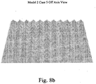
- Model 2 Case 5 shown in Figs. 8a , 8b and Fig. 9 shows an example of another case where coordinating colors are not realized, that is, where colors of similar hue are not presented to the viewer at the on-axis orientation and the observed color is not quite as dramatic. In this case, coordinating colors are still present in the off-axis orientation resulting the in the reinforced gold color on the off-axis view.
- TABLE 2E Model 2 Case 5 - Blue to Red (0.8) Viewing Angle 45 Degrees MgF2 Thickness 270nm Face (1) and (2) Ratio 1.0 Face (3) and (4) Ratio 0.8
- the most ideal unit cell height to base ratio has proven to be the "Golden Pyramid" ratio with a height to base ratio of 0.636. Of the ratios used in our simulations, this ratio showed the least amount of apparent color variation over a typical range of substrate viewing angles which ranged from 25 degrees to 65 degrees above the substrate plane. The 0.8 height to base ratio was also found to be acceptable.
- the optimal height to base ratio appears to be in the range of 0.6 to 0.8.
- the assumption was that the off-axis faces were always receiving 80% of the coating that the on-axis faces were receiving. This is probably not feasible as the height to base ratio becomes small due to the coating geometry constraints.
- there is an optimal height to base ratio of the unit cell that produces the least amount of visual variation as the viewing angle from the substrate plane is varied.
- the pyramidal array can be formed by embossing a flexible or rigid deformable substrate from an appropriate master.
- the master can be made by diamond cutting or other suitable micromachining techniques such as electron beam lithography, ion milling, or other microreplication techniques. We believe that techniques can be employed to make masters that could be used in an embossing process.
- an anilox roller having indented pyramids and other shapes used in the printing as a template for making a positive nickel master by means of electro less nickel with a release layer, followed by growing a nickel daughter image from the nickel master which in turn is used to emboss a UV curable lacquer on a web to make positive pyramidal shapes.
- Information regarding anilox rollers can currently be found on the Internet at http://www.harperimage.comJanilox-specify.asp and http://www.appliedlaser.co.uk/anilox.htm.
- the dimensions of the pyramids are below eye resolution of about 100 microns.
- the height of the pyramids is preferably below 100 microns. This is important from a security viewpoint because it would be non-obvious to an observer as to why one color shift is occurring.
- embodiments of this invention use forms of linear coding by varying the heights of pyramids in a linear sequence to create an overt or covert readable "bar code” effect depending on the degree of modulation used.
- Overt images, symbols, words could be written into the pattern by geometrical variations to the unit cell. Alteration of cell height, orientation, cell size, facet angles could all be used to encode information.
- Fig. 17 shows indicia in the form of a letter "A" provided by exposing the substrate in this region.
- a visible logo is formed by orienting a particular region of pyramids for forming a logo, at 45 degrees to other pyramids which serve as a contrasting background within the security device, and coating all of the pyramids with a same color shifting coating.
- the pyramids forming the logo appear in a first color distinct from the color of the background pyramids.
- the colors change, and at a particular angle, the colors of the two regions appear to switch.
- indicia in the form of a logo or text can be encoded within the array of pyramids or between the pyramids. Regions of pyramids can have different geometries than others, thereby providing a visual distinction so as to define a logo or text.
- a security thread in which most of the area on the web has the same pyramid geometries but in certain regions some of the pyramids have different face angles. This would allow an image to appear when the device is rotated.
- some frusto-pyramids can be provided with flat tops, within a region, thereby defining a logo or indicia distinguishable from other regular shaped pyramids. Essentially what is required in all of these embodiments is a region, within a larger region of pyramids that is visually distinguishable in such a manner as to define indicia.
- pyramids having flat planar surfaces have been described, however pyramids having one or more faces having diffractive grooves formed therein would provide additional effects to the color shifting described.
- pyramids having facial grooves extending from the base to the apex can be provided, and stepped pyramids can also be provided.
- the stepped pyramids can have steps at small diffractive widths or can be larger.
- Aluminized pyramids can be provided in a selected pattern purposely dispersed within the optically variable coated pyramids so as to form a logo or indica that is distinguishable from the color shifting coated pyramids.
- FIG. 15 shows an embodiment wherein planar spaces of the substrate are shown between upstanding pyramids, and in Fig. 16 , upstanding and inverted pyramids are shown juxtaposed.
- Pyramids can also be provided that are skewed relative to the machine direction shown in the figures.
- the pyramid faces could also be etched to form diffractive surfaces as could the flat areas among the pyramid.
Landscapes
- Physics & Mathematics (AREA)
- General Physics & Mathematics (AREA)
- Optics & Photonics (AREA)
- Printing Methods (AREA)
- Diffracting Gratings Or Hologram Optical Elements (AREA)
- Electrochromic Elements, Electrophoresis, Or Variable Reflection Or Absorption Elements (AREA)
- Optical Filters (AREA)
- Mechanical Light Control Or Optical Switches (AREA)
- Illuminated Signs And Luminous Advertising (AREA)
Claims (15)
- Dispositif optiquement variable comprenant un substrat doté d'un réseau de structures formées sur, dans ou supportées par celui-ci, dans lequel chacune des structures forme une structure pyramidale et dans lequel chaque structure pyramidale a au moins trois faces inclinées et dans lequel plus d'une couleur vue en visualisant les pyramides varie lorsqu'on tourne le substrat d'au moins 30 degrés autour d'un axe orthogonal par rapport au substrat, caractérisé en ce que lesdites structures sont plaquées d'un revêtement optiquement variable changeant de couleur.
- Dispositif optiquement variable selon la revendication 1, dans lequel les dimensions des pyramides s'élèvent à moins de 100 microns.
- Dispositif optiquement variable selon la revendication 1, dans lequel des espaces ou des structures qui diffèrent du réseau de structures sont prévus entre ledit réseau de structures de manière à former des impressions visibles dont la taille est discernable sans grossissement.
- Dispositif optiquement variable selon la revendication 1, doté d'impressions visibles formées dedans et pouvant être distinguées du réseau de structures pyramidales.
- Dispositif optiquement variable selon la revendication 1, dans lequel le rapport entre la hauteur et la base d'au moins 50% des structures pyramidales est de l'ordre de 0,4 à 1,4.
- Dispositif optiquement variable selon la revendication 1, dans lequel une première pluralité des structures pyramidales sont orientées dans une première orientation prédéterminée et dans lequel une seconde pluralité des structures pyramidales sont orientées dans une seconde orientation différente, de sorte que la première pluralité de structures paraissent avoir une couleur différente de celle de la seconde pluralité de structures.
- Dispositif optiquement variable selon la revendication 1, dans lequel un premier groupe de structures pyramidales contiguës diffère d'un second groupe de structures pyramidales contiguës et dans lequel les premier et second groupes forment des impressions pouvant être distinguées visuellement.
- Dispositif optiquement variable selon la revendication 1, dans lequel la pente de chacune des faces d'une structure pyramidale décrit un angle différent avec le substrat.
- Dispositif optiquement variable selon la revendication 1, dans lequel la pente de chacune des faces d'une structure pyramidale décrit un angle identique avec le substrat.
- Dispositif optiquement variable selon la revendication 1, dans lequel la pluralité de structures forment un réseau de structures pyramidales et dans lequel l'épaisseur du revêtement optiquement variable sur chacune des faces est une même épaisseur sensiblement uniforme.
- Dispositif optiquement variable selon la revendication 1, dans lequel l'épaisseur du revêtement optiquement variable sur des faces adjacentes de la pyramide est une épaisseur différente.
- Dispositif optiquement variable selon la revendication 1, dans lequel le revêtement est une structure Fabry-Pérot à simple cavité.
- Dispositif optiquement variable selon la revendication 1, dans lequel une pluralité de pyramides sont au moins une sorte de pyramide parmi les pyramides tétraèdres, les pyramides carrées, les pyramides pentagonales et les pyramides à tronc conique à dessus plats.
- Dispositif optiquement variable selon la revendication 13, dans lequel au moins une des faces sur au moins une pluralité des pyramides ont une grille de diffraction formée à l'intérieur.
- Procédé de création d'un dispositif qui présente de la couleur par rotation, comprenant :a) la création d'un substrat dans lequel ou sur lequel un réseau de petites structures pyramidales ou pyramidales inversées est formé, les structures pyramidales étant dimensionnées de manière à ne pouvoir être discernées par l'œil humain que par grossissement et chaque structure pyramidale ayant au moins trois faces inclinées ; et,b) le revêtement des structures pyramidales ou pyramidales inversées avec un revêtement multicouche optiquement variable changeant de couleur de telle sorte que plus d'une couleur vue en visualisant les pyramides varie lorsqu'on tourne le substrat d'au moins 30 degrés autour d'un axe orthogonal par rapport au substrat.
Applications Claiming Priority (2)
| Application Number | Priority Date | Filing Date | Title |
|---|---|---|---|
| US91635507P | 2007-05-07 | 2007-05-07 | |
| US124007P | 2007-10-31 | 2007-10-31 |
Publications (4)
| Publication Number | Publication Date |
|---|---|
| EP1990210A2 EP1990210A2 (fr) | 2008-11-12 |
| EP1990210A3 EP1990210A3 (fr) | 2013-12-11 |
| EP1990210B1 EP1990210B1 (fr) | 2015-01-21 |
| EP1990210B2 true EP1990210B2 (fr) | 2021-12-22 |
Family
ID=39617543
Family Applications (1)
| Application Number | Title | Priority Date | Filing Date |
|---|---|---|---|
| EP08155661.5A Active EP1990210B2 (fr) | 2007-05-07 | 2008-05-05 | Surfaces structurées qui exposent des couleurs par rotation |
Country Status (7)
| Country | Link |
|---|---|
| US (1) | US8124217B2 (fr) |
| EP (1) | EP1990210B2 (fr) |
| JP (1) | JP5363756B2 (fr) |
| KR (1) | KR101562991B1 (fr) |
| AU (1) | AU2008201903B2 (fr) |
| CA (1) | CA2630425C (fr) |
| TW (1) | TWI545337B (fr) |
Families Citing this family (14)
| Publication number | Priority date | Publication date | Assignee | Title |
|---|---|---|---|---|
| EP2161598B2 (fr) | 2008-09-05 | 2021-06-09 | Viavi Solutions Inc. | Dispositif optique démontrant de la couleur lors de la rotation |
| EP2230539B1 (fr) | 2009-03-19 | 2019-12-04 | Viavi Solutions Inc. | Formation de motifs dans une couche d'espaceur dans un filtre d'interférence |
| TWI453927B (zh) * | 2011-06-29 | 2014-09-21 | Ind Tech Res Inst | 多重反射結構以及光電元件 |
| EP2594149A1 (fr) * | 2011-11-18 | 2013-05-22 | Fabrica Nacional De Moneda Y Timbre - Real Casa De La Moneda | Objet comportant une région de sa surface adaptée pour montrer plusieurs images |
| JP2016080848A (ja) * | 2014-10-16 | 2016-05-16 | 凸版印刷株式会社 | 表示体及び表示体付き物品 |
| JP6609973B2 (ja) * | 2015-04-07 | 2019-11-27 | 凸版印刷株式会社 | 表示体及び情報印刷物 |
| DE102016110314A1 (de) * | 2015-07-07 | 2017-01-12 | Toyota Motor Engineering & Manufacturing North America, Inc. | Omnidirektionale rote strukturelle farbe hoher chroma mit kombination aus halbleiterabsorber- und dielektrischen absorberschichten |
| GB2553555B (en) * | 2016-09-08 | 2019-12-11 | De La Rue Int Ltd | Security devices and methods of manufacture thereof |
| GB2562699B (en) | 2017-02-03 | 2020-07-22 | De La Rue Int Ltd | Method of forming a security device |
| GB2562198B (en) * | 2017-02-03 | 2021-05-05 | De La Rue Int Ltd | Method of forming a security document |
| GB2563187B (en) | 2017-02-03 | 2020-07-22 | De La Rue Int Ltd | Method of forming a security sheet substrate |
| FR3087386B1 (fr) * | 2018-10-22 | 2020-12-11 | Oberthur Fiduciaire Sas | Element de securite pour un document-valeur, son procede de fabrication et document-valeur qui le comporte |
| JP6764990B1 (ja) | 2019-11-29 | 2020-10-07 | 株式会社ドワンゴ | 表示媒体、処理装置および処理プログラム |
| CN113545573A (zh) * | 2021-07-23 | 2021-10-26 | 浙江运发实业有限公司 | 纪念币及其防伪隐形方法 |
Citations (4)
| Publication number | Priority date | Publication date | Assignee | Title |
|---|---|---|---|---|
| WO2003095657A2 (fr) † | 2002-05-14 | 2003-11-20 | Leonhard Kurz Gmbh & Co. Kg | Element optiquement variable |
| WO2006018232A1 (fr) † | 2004-08-13 | 2006-02-23 | Giesecke & Devrient Gmbh | Support de donnees ayant une structure optiquement variable |
| WO2007079851A1 (fr) † | 2005-12-21 | 2007-07-19 | Giesecke & Devrient Gmbh | Elément de sécurité à variation d'aspect et son procédé de fabrication |
| WO2007093300A2 (fr) † | 2006-02-13 | 2007-08-23 | Giesecke & Devrient Gmbh | Élément de sécurité doté d'une structure à effet optique variable |
Family Cites Families (20)
| Publication number | Priority date | Publication date | Assignee | Title |
|---|---|---|---|---|
| US3338730A (en) | 1964-02-18 | 1967-08-29 | Little Inc A | Method of treating reflective surfaces to make them multihued and resulting product |
| US5766738A (en) | 1979-12-28 | 1998-06-16 | Flex Products, Inc. | Paired optically variable article with paired optically variable structures and ink, paint and foil incorporating the same and method |
| DE69218582T2 (de) | 1992-02-21 | 1997-07-10 | Hashimoto Forming Kogyo Co | Lackierung mit magnetisch hergestelltem Muster und lackiertes Produkt mit magnetisch hergestelltem Muster |
| GB9524862D0 (en) * | 1995-12-06 | 1996-02-07 | The Technology Partnership Plc | Colour diffractive structure |
| US5763049A (en) * | 1996-04-30 | 1998-06-09 | Minnesota Mining And Manufacturing Company | Formed ultra-flexible retroreflective cube-corner composite sheeting with target optical properties and method for making same |
| US6120636A (en) * | 1998-01-26 | 2000-09-19 | Reflexite Corporation | Apparatus and method for producing retroreflective material having printed patterns thereon |
| US7667895B2 (en) * | 1999-07-08 | 2010-02-23 | Jds Uniphase Corporation | Patterned structures with optically variable effects |
| US6761959B1 (en) * | 1999-07-08 | 2004-07-13 | Flex Products, Inc. | Diffractive surfaces with color shifting backgrounds |
| KR100739242B1 (ko) * | 2000-01-21 | 2007-07-12 | 플렉스 프로덕츠, 인코포레이티드 | 가변적 광학 특성의 보안 장치 |
| US20020160194A1 (en) | 2001-04-27 | 2002-10-31 | Flex Products, Inc. | Multi-layered magnetic pigments and foils |
| US6841238B2 (en) | 2002-04-05 | 2005-01-11 | Flex Products, Inc. | Chromatic diffractive pigments and foils |
| US7241489B2 (en) | 2002-09-13 | 2007-07-10 | Jds Uniphase Corporation | Opaque flake for covert security applications |
| US7645510B2 (en) | 2002-09-13 | 2010-01-12 | Jds Uniphase Corporation | Provision of frames or borders around opaque flakes for covert security applications |
| EP1549505A4 (fr) * | 2002-10-07 | 2006-04-19 | Note Printing Au Ltd | Dispositifs estampes a couleurs changeantes |
| EP1611466B8 (fr) * | 2003-03-21 | 2007-10-10 | OVD Kinegram AG | Procédé de fabrication de deux microstructures superposées |
| NL1027715C2 (nl) * | 2004-12-10 | 2006-06-19 | Sdu Identification Bv | Identiteitsdocument. |
| DE102005028162A1 (de) * | 2005-02-18 | 2006-12-28 | Giesecke & Devrient Gmbh | Sicherheitselement und Verfahren zu seiner Herstellung |
| CA2537732A1 (fr) * | 2005-04-06 | 2006-10-06 | Jds Uniphase Corporation | Particules scintillantes a saturation elevee de couleurs changeantes en fonction des conditions optiques |
| AU2006202315B2 (en) * | 2005-06-17 | 2011-01-27 | Viavi Solutions Inc. | Covert security coating |
| CA2564764C (fr) * | 2005-10-25 | 2014-05-13 | Jds Uniphase Corporation | Structures optiques a motif avec fonction de securite amelioree |
-
2008
- 2008-04-29 AU AU2008201903A patent/AU2008201903B2/en active Active
- 2008-05-02 CA CA2630425A patent/CA2630425C/fr active Active
- 2008-05-02 JP JP2008120743A patent/JP5363756B2/ja active Active
- 2008-05-02 KR KR1020080041539A patent/KR101562991B1/ko active IP Right Grant
- 2008-05-05 EP EP08155661.5A patent/EP1990210B2/fr active Active
- 2008-05-06 TW TW097116697A patent/TWI545337B/zh active
- 2008-05-07 US US12/151,511 patent/US8124217B2/en active Active
Patent Citations (4)
| Publication number | Priority date | Publication date | Assignee | Title |
|---|---|---|---|---|
| WO2003095657A2 (fr) † | 2002-05-14 | 2003-11-20 | Leonhard Kurz Gmbh & Co. Kg | Element optiquement variable |
| WO2006018232A1 (fr) † | 2004-08-13 | 2006-02-23 | Giesecke & Devrient Gmbh | Support de donnees ayant une structure optiquement variable |
| WO2007079851A1 (fr) † | 2005-12-21 | 2007-07-19 | Giesecke & Devrient Gmbh | Elément de sécurité à variation d'aspect et son procédé de fabrication |
| WO2007093300A2 (fr) † | 2006-02-13 | 2007-08-23 | Giesecke & Devrient Gmbh | Élément de sécurité doté d'une structure à effet optique variable |
Non-Patent Citations (2)
| Title |
|---|
| Provisional Application US 1240 P † |
| Provisional Application US 916355 P † |
Also Published As
| Publication number | Publication date |
|---|---|
| CA2630425A1 (fr) | 2008-11-07 |
| JP5363756B2 (ja) | 2013-12-11 |
| KR101562991B1 (ko) | 2015-10-30 |
| CA2630425C (fr) | 2015-09-29 |
| AU2008201903A1 (en) | 2008-11-27 |
| JP2008276239A (ja) | 2008-11-13 |
| AU2008201903B2 (en) | 2013-03-28 |
| KR20080099148A (ko) | 2008-11-12 |
| EP1990210B1 (fr) | 2015-01-21 |
| EP1990210A2 (fr) | 2008-11-12 |
| EP1990210A3 (fr) | 2013-12-11 |
| US8124217B2 (en) | 2012-02-28 |
| TW200912362A (en) | 2009-03-16 |
| US20080286501A1 (en) | 2008-11-20 |
| TWI545337B (zh) | 2016-08-11 |
Similar Documents
| Publication | Publication Date | Title |
|---|---|---|
| EP1990210B2 (fr) | Surfaces structurées qui exposent des couleurs par rotation | |
| AU2008202101B2 (en) | Structured surfaces that exhibit color by rotation | |
| EP2507068B1 (fr) | Élément de sécurité, document de valeur présentant un tel élément de sécurité, et procédé de production d'un élément de sécurité | |
| JP5242394B2 (ja) | マイクロ屈折画像 | |
| EP3059093A1 (fr) | Élement de securite, document de valeur dote d'un tel element de securite ainsi que procede de fabrication d'un element de securite | |
| US10792947B2 (en) | Optical structure | |
| AU2020257828A1 (en) | Optical switch devices | |
| CN107921810B (zh) | 光学可变的防伪元件 | |
| JP6948030B2 (ja) | 色彩変化印刷物 | |
| CN101329828B (zh) | 通过旋转展示颜色的结构表面 | |
| EP3034315B1 (fr) | Élement de securite, son procede de fabrication et support de donnees dote d'un element de securite | |
| KR101170657B1 (ko) | 격자 구조를 이용한 위조방지용 시트 제조방법 | |
| CA3147129A1 (fr) | Dispositifs de securite et leurs procedes de fabrication |
Legal Events
| Date | Code | Title | Description |
|---|---|---|---|
| PUAI | Public reference made under article 153(3) epc to a published international application that has entered the european phase |
Free format text: ORIGINAL CODE: 0009012 |
|
| AK | Designated contracting states |
Kind code of ref document: A2 Designated state(s): AT BE BG CH CY CZ DE DK EE ES FI FR GB GR HR HU IE IS IT LI LT LU LV MC MT NL NO PL PT RO SE SI SK TR |
|
| AX | Request for extension of the european patent |
Extension state: AL BA MK RS |
|
| PUAL | Search report despatched |
Free format text: ORIGINAL CODE: 0009013 |
|
| AK | Designated contracting states |
Kind code of ref document: A3 Designated state(s): AT BE BG CH CY CZ DE DK EE ES FI FR GB GR HR HU IE IS IT LI LT LU LV MC MT NL NO PL PT RO SE SI SK TR |
|
| AX | Request for extension of the european patent |
Extension state: AL BA MK RS |
|
| RIC1 | Information provided on ipc code assigned before grant |
Ipc: B42D 15/00 20060101AFI20131106BHEP Ipc: B42D 15/10 20060101ALI20131106BHEP |
|
| REG | Reference to a national code |
Ref country code: DE Ref legal event code: R079 Ref document number: 602008036425 Country of ref document: DE Free format text: PREVIOUS MAIN CLASS: B42D0015000000 Ipc: B42D0025000000 |
|
| 17P | Request for examination filed |
Effective date: 20140603 |
|
| GRAP | Despatch of communication of intention to grant a patent |
Free format text: ORIGINAL CODE: EPIDOSNIGR1 |
|
| RBV | Designated contracting states (corrected) |
Designated state(s): AT BE BG CH CY CZ DE DK EE ES FI FR GB GR HR HU IE IS IT LI LT LU LV MC MT NL NO PL PT RO SE SI SK TR |
|
| RIC1 | Information provided on ipc code assigned before grant |
Ipc: B42D 25/00 20140101AFI20140618BHEP |
|
| INTG | Intention to grant announced |
Effective date: 20140717 |
|
| RIN1 | Information on inventor provided before grant (corrected) |
Inventor name: TEITELBAUM, NEIL Inventor name: WITZMAN, MATTHEW, R Inventor name: PHILLIPS, ROGER, W Inventor name: RAKSHA, VLADIMIR P. Inventor name: KURMAN, ERIC WILLIAM |
|
| AKX | Designation fees paid |
Designated state(s): AT BE BG CH CY CZ DE DK EE ES FI FR GB GR HR HU IE IS IT LI LT LU LV MC MT NL NO PL PT RO SE SI SK TR |
|
| GRAP | Despatch of communication of intention to grant a patent |
Free format text: ORIGINAL CODE: EPIDOSNIGR1 |
|
| INTG | Intention to grant announced |
Effective date: 20141010 |
|
| GRAS | Grant fee paid |
Free format text: ORIGINAL CODE: EPIDOSNIGR3 |
|
| GRAA | (expected) grant |
Free format text: ORIGINAL CODE: 0009210 |
|
| STAA | Information on the status of an ep patent application or granted ep patent |
Free format text: STATUS: THE PATENT HAS BEEN GRANTED |
|
| AK | Designated contracting states |
Kind code of ref document: B1 Designated state(s): AT BE BG CH CY CZ DE DK EE ES FI FR GB GR HR HU IE IS IT LI LT LU LV MC MT NL NO PL PT RO SE SI SK TR |
|
| REG | Reference to a national code |
Ref country code: GB Ref legal event code: FG4D |
|
| REG | Reference to a national code |
Ref country code: CH Ref legal event code: EP |
|
| REG | Reference to a national code |
Ref country code: IE Ref legal event code: FG4D |
|
| REG | Reference to a national code |
Ref country code: AT Ref legal event code: REF Ref document number: 707660 Country of ref document: AT Kind code of ref document: T Effective date: 20150215 |
|
| REG | Reference to a national code |
Ref country code: DE Ref legal event code: R096 Ref document number: 602008036425 Country of ref document: DE Effective date: 20150305 |
|
| REG | Reference to a national code |
Ref country code: NL Ref legal event code: VDEP Effective date: 20150121 |
|
| REG | Reference to a national code |
Ref country code: AT Ref legal event code: MK05 Ref document number: 707660 Country of ref document: AT Kind code of ref document: T Effective date: 20150121 |
|
| REG | Reference to a national code |
Ref country code: LT Ref legal event code: MG4D |
|
| PG25 | Lapsed in a contracting state [announced via postgrant information from national office to epo] |
Ref country code: SE Free format text: LAPSE BECAUSE OF FAILURE TO SUBMIT A TRANSLATION OF THE DESCRIPTION OR TO PAY THE FEE WITHIN THE PRESCRIBED TIME-LIMIT Effective date: 20150121 Ref country code: NO Free format text: LAPSE BECAUSE OF FAILURE TO SUBMIT A TRANSLATION OF THE DESCRIPTION OR TO PAY THE FEE WITHIN THE PRESCRIBED TIME-LIMIT Effective date: 20150421 Ref country code: FI Free format text: LAPSE BECAUSE OF FAILURE TO SUBMIT A TRANSLATION OF THE DESCRIPTION OR TO PAY THE FEE WITHIN THE PRESCRIBED TIME-LIMIT Effective date: 20150121 Ref country code: HR Free format text: LAPSE BECAUSE OF FAILURE TO SUBMIT A TRANSLATION OF THE DESCRIPTION OR TO PAY THE FEE WITHIN THE PRESCRIBED TIME-LIMIT Effective date: 20150121 Ref country code: BG Free format text: LAPSE BECAUSE OF FAILURE TO SUBMIT A TRANSLATION OF THE DESCRIPTION OR TO PAY THE FEE WITHIN THE PRESCRIBED TIME-LIMIT Effective date: 20150421 Ref country code: ES Free format text: LAPSE BECAUSE OF FAILURE TO SUBMIT A TRANSLATION OF THE DESCRIPTION OR TO PAY THE FEE WITHIN THE PRESCRIBED TIME-LIMIT Effective date: 20150121 Ref country code: LT Free format text: LAPSE BECAUSE OF FAILURE TO SUBMIT A TRANSLATION OF THE DESCRIPTION OR TO PAY THE FEE WITHIN THE PRESCRIBED TIME-LIMIT Effective date: 20150121 |
|
| PG25 | Lapsed in a contracting state [announced via postgrant information from national office to epo] |
Ref country code: IS Free format text: LAPSE BECAUSE OF FAILURE TO SUBMIT A TRANSLATION OF THE DESCRIPTION OR TO PAY THE FEE WITHIN THE PRESCRIBED TIME-LIMIT Effective date: 20150521 Ref country code: PL Free format text: LAPSE BECAUSE OF FAILURE TO SUBMIT A TRANSLATION OF THE DESCRIPTION OR TO PAY THE FEE WITHIN THE PRESCRIBED TIME-LIMIT Effective date: 20150121 Ref country code: AT Free format text: LAPSE BECAUSE OF FAILURE TO SUBMIT A TRANSLATION OF THE DESCRIPTION OR TO PAY THE FEE WITHIN THE PRESCRIBED TIME-LIMIT Effective date: 20150121 Ref country code: NL Free format text: LAPSE BECAUSE OF FAILURE TO SUBMIT A TRANSLATION OF THE DESCRIPTION OR TO PAY THE FEE WITHIN THE PRESCRIBED TIME-LIMIT Effective date: 20150121 Ref country code: GR Free format text: LAPSE BECAUSE OF FAILURE TO SUBMIT A TRANSLATION OF THE DESCRIPTION OR TO PAY THE FEE WITHIN THE PRESCRIBED TIME-LIMIT Effective date: 20150422 Ref country code: LV Free format text: LAPSE BECAUSE OF FAILURE TO SUBMIT A TRANSLATION OF THE DESCRIPTION OR TO PAY THE FEE WITHIN THE PRESCRIBED TIME-LIMIT Effective date: 20150121 |
|
| REG | Reference to a national code |
Ref country code: DE Ref legal event code: R026 Ref document number: 602008036425 Country of ref document: DE |
|
| PG25 | Lapsed in a contracting state [announced via postgrant information from national office to epo] |
Ref country code: SK Free format text: LAPSE BECAUSE OF FAILURE TO SUBMIT A TRANSLATION OF THE DESCRIPTION OR TO PAY THE FEE WITHIN THE PRESCRIBED TIME-LIMIT Effective date: 20150121 Ref country code: CZ Free format text: LAPSE BECAUSE OF FAILURE TO SUBMIT A TRANSLATION OF THE DESCRIPTION OR TO PAY THE FEE WITHIN THE PRESCRIBED TIME-LIMIT Effective date: 20150121 Ref country code: RO Free format text: LAPSE BECAUSE OF FAILURE TO SUBMIT A TRANSLATION OF THE DESCRIPTION OR TO PAY THE FEE WITHIN THE PRESCRIBED TIME-LIMIT Effective date: 20150121 Ref country code: EE Free format text: LAPSE BECAUSE OF FAILURE TO SUBMIT A TRANSLATION OF THE DESCRIPTION OR TO PAY THE FEE WITHIN THE PRESCRIBED TIME-LIMIT Effective date: 20150121 Ref country code: DK Free format text: LAPSE BECAUSE OF FAILURE TO SUBMIT A TRANSLATION OF THE DESCRIPTION OR TO PAY THE FEE WITHIN THE PRESCRIBED TIME-LIMIT Effective date: 20150121 |
|
| PLBI | Opposition filed |
Free format text: ORIGINAL CODE: 0009260 |
|
| PLAX | Notice of opposition and request to file observation + time limit sent |
Free format text: ORIGINAL CODE: EPIDOSNOBS2 |
|
| 26 | Opposition filed |
Opponent name: GIESECKE & DEVRIENT GMBH Effective date: 20151021 |
|
| PG25 | Lapsed in a contracting state [announced via postgrant information from national office to epo] |
Ref country code: IT Free format text: LAPSE BECAUSE OF FAILURE TO SUBMIT A TRANSLATION OF THE DESCRIPTION OR TO PAY THE FEE WITHIN THE PRESCRIBED TIME-LIMIT Effective date: 20150121 |
|
| REG | Reference to a national code |
Ref country code: CH Ref legal event code: PL |
|
| PG25 | Lapsed in a contracting state [announced via postgrant information from national office to epo] |
Ref country code: LI Free format text: LAPSE BECAUSE OF NON-PAYMENT OF DUE FEES Effective date: 20150531 Ref country code: MC Free format text: LAPSE BECAUSE OF FAILURE TO SUBMIT A TRANSLATION OF THE DESCRIPTION OR TO PAY THE FEE WITHIN THE PRESCRIBED TIME-LIMIT Effective date: 20150121 Ref country code: CH Free format text: LAPSE BECAUSE OF NON-PAYMENT OF DUE FEES Effective date: 20150531 Ref country code: LU Free format text: LAPSE BECAUSE OF FAILURE TO SUBMIT A TRANSLATION OF THE DESCRIPTION OR TO PAY THE FEE WITHIN THE PRESCRIBED TIME-LIMIT Effective date: 20150505 |
|
| REG | Reference to a national code |
Ref country code: IE Ref legal event code: MM4A |
|
| REG | Reference to a national code |
Ref country code: FR Ref legal event code: ST Effective date: 20160129 |
|
| PG25 | Lapsed in a contracting state [announced via postgrant information from national office to epo] |
Ref country code: SI Free format text: LAPSE BECAUSE OF FAILURE TO SUBMIT A TRANSLATION OF THE DESCRIPTION OR TO PAY THE FEE WITHIN THE PRESCRIBED TIME-LIMIT Effective date: 20150121 |
|
| PLBB | Reply of patent proprietor to notice(s) of opposition received |
Free format text: ORIGINAL CODE: EPIDOSNOBS3 |
|
| RAP2 | Party data changed (patent owner data changed or rights of a patent transferred) |
Owner name: VIAVI SOLUTIONS INC. |
|
| PG25 | Lapsed in a contracting state [announced via postgrant information from national office to epo] |
Ref country code: IE Free format text: LAPSE BECAUSE OF NON-PAYMENT OF DUE FEES Effective date: 20150505 |
|
| PG25 | Lapsed in a contracting state [announced via postgrant information from national office to epo] |
Ref country code: BE Free format text: LAPSE BECAUSE OF FAILURE TO SUBMIT A TRANSLATION OF THE DESCRIPTION OR TO PAY THE FEE WITHIN THE PRESCRIBED TIME-LIMIT Effective date: 20150121 Ref country code: FR Free format text: LAPSE BECAUSE OF NON-PAYMENT OF DUE FEES Effective date: 20150601 |
|
| REG | Reference to a national code |
Ref country code: DE Ref legal event code: R082 Ref document number: 602008036425 Country of ref document: DE Representative=s name: MURGITROYD & COMPANY, DE |
|
| REG | Reference to a national code |
Ref country code: DE Ref legal event code: R082 Ref document number: 602008036425 Country of ref document: DE Representative=s name: MURGITROYD & COMPANY, DE Ref country code: DE Ref legal event code: R081 Ref document number: 602008036425 Country of ref document: DE Owner name: VIAVI SOLUTIONS INC. (N. D. GES. D. STAATES DE, US Free format text: FORMER OWNER: JDS UNIPHASE CORP., MILPITAS, CALIF., US |
|
| PG25 | Lapsed in a contracting state [announced via postgrant information from national office to epo] |
Ref country code: HU Free format text: LAPSE BECAUSE OF FAILURE TO SUBMIT A TRANSLATION OF THE DESCRIPTION OR TO PAY THE FEE WITHIN THE PRESCRIBED TIME-LIMIT; INVALID AB INITIO Effective date: 20080505 |
|
| PG25 | Lapsed in a contracting state [announced via postgrant information from national office to epo] |
Ref country code: CY Free format text: LAPSE BECAUSE OF FAILURE TO SUBMIT A TRANSLATION OF THE DESCRIPTION OR TO PAY THE FEE WITHIN THE PRESCRIBED TIME-LIMIT Effective date: 20150121 |
|
| PG25 | Lapsed in a contracting state [announced via postgrant information from national office to epo] |
Ref country code: PT Free format text: LAPSE BECAUSE OF FAILURE TO SUBMIT A TRANSLATION OF THE DESCRIPTION OR TO PAY THE FEE WITHIN THE PRESCRIBED TIME-LIMIT Effective date: 20150521 |
|
| PG25 | Lapsed in a contracting state [announced via postgrant information from national office to epo] |
Ref country code: TR Free format text: LAPSE BECAUSE OF FAILURE TO SUBMIT A TRANSLATION OF THE DESCRIPTION OR TO PAY THE FEE WITHIN THE PRESCRIBED TIME-LIMIT Effective date: 20150121 |
|
| RIC2 | Information provided on ipc code assigned after grant |
Ipc: G02B 5/18 20060101ALI20171110BHEP Ipc: B42D 25/36 20140101ALI20171110BHEP Ipc: B42D 25/324 20140101ALI20171110BHEP Ipc: G02B 5/28 20060101ALI20171110BHEP Ipc: G02B 5/04 20060101AFI20171110BHEP Ipc: B42D 25/373 20140101ALI20171110BHEP |
|
| APAH | Appeal reference modified |
Free format text: ORIGINAL CODE: EPIDOSCREFNO |
|
| APBM | Appeal reference recorded |
Free format text: ORIGINAL CODE: EPIDOSNREFNO |
|
| APBP | Date of receipt of notice of appeal recorded |
Free format text: ORIGINAL CODE: EPIDOSNNOA2O |
|
| APBQ | Date of receipt of statement of grounds of appeal recorded |
Free format text: ORIGINAL CODE: EPIDOSNNOA3O |
|
| RAP2 | Party data changed (patent owner data changed or rights of a patent transferred) |
Owner name: VIAVI SOLUTIONS INC. |
|
| PLAB | Opposition data, opponent's data or that of the opponent's representative modified |
Free format text: ORIGINAL CODE: 0009299OPPO |
|
| R26 | Opposition filed (corrected) |
Opponent name: GIESECKE+DEVRIENT CURRENCY TECHNOLOGY GMBH Effective date: 20151021 |
|
| APBU | Appeal procedure closed |
Free format text: ORIGINAL CODE: EPIDOSNNOA9O |
|
| PUAH | Patent maintained in amended form |
Free format text: ORIGINAL CODE: 0009272 |
|
| STAA | Information on the status of an ep patent application or granted ep patent |
Free format text: STATUS: PATENT MAINTAINED AS AMENDED |
|
| 27A | Patent maintained in amended form |
Effective date: 20211222 |
|
| AK | Designated contracting states |
Kind code of ref document: B2 Designated state(s): AT BE BG CH CY CZ DE DK EE ES FI FR GB GR HR HU IE IS IT LI LT LU LV MC MT NL NO PL PT RO SE SI SK TR |
|
| REG | Reference to a national code |
Ref country code: DE Ref legal event code: R102 Ref document number: 602008036425 Country of ref document: DE |
|
| PLAB | Opposition data, opponent's data or that of the opponent's representative modified |
Free format text: ORIGINAL CODE: 0009299OPPO |
|
| R26 | Opposition filed (corrected) |
Opponent name: GIESECKE+DEVRIENT CURRENCY TECHNOLOGY GMBH Effective date: 20151021 |
|
| P01 | Opt-out of the competence of the unified patent court (upc) registered |
Effective date: 20230530 |
|
| PGFP | Annual fee paid to national office [announced via postgrant information from national office to epo] |
Ref country code: DE Payment date: 20230526 Year of fee payment: 16 |
|
| PGFP | Annual fee paid to national office [announced via postgrant information from national office to epo] |
Ref country code: MT Payment date: 20230608 Year of fee payment: 16 Ref country code: GB Payment date: 20230530 Year of fee payment: 16 |