EP1990194A2 - Fluidsteuerungsvorrichtung - Google Patents
Fluidsteuerungsvorrichtung Download PDFInfo
- Publication number
- EP1990194A2 EP1990194A2 EP20080155771 EP08155771A EP1990194A2 EP 1990194 A2 EP1990194 A2 EP 1990194A2 EP 20080155771 EP20080155771 EP 20080155771 EP 08155771 A EP08155771 A EP 08155771A EP 1990194 A2 EP1990194 A2 EP 1990194A2
- Authority
- EP
- European Patent Office
- Prior art keywords
- valve
- stator body
- end portion
- cam
- rotor group
- Prior art date
- Legal status (The legal status is an assumption and is not a legal conclusion. Google has not performed a legal analysis and makes no representation as to the accuracy of the status listed.)
- Withdrawn
Links
- 239000012530 fluid Substances 0.000 title claims abstract description 13
- 238000005096 rolling process Methods 0.000 claims description 4
- 150000001875 compounds Chemical class 0.000 claims description 3
- 238000007789 sealing Methods 0.000 claims description 3
- 229920001971 elastomer Polymers 0.000 claims description 2
- 239000000806 elastomer Substances 0.000 claims description 2
- 229920001973 fluoroelastomer Polymers 0.000 claims description 2
- 238000005406 washing Methods 0.000 description 3
- 229920006169 Perfluoroelastomer Polymers 0.000 description 2
- 238000004891 communication Methods 0.000 description 1
- 238000006073 displacement reaction Methods 0.000 description 1
- 230000001788 irregular Effects 0.000 description 1
- 239000007788 liquid Substances 0.000 description 1
- 230000005923 long-lasting effect Effects 0.000 description 1
- 238000012423 maintenance Methods 0.000 description 1
- 238000004519 manufacturing process Methods 0.000 description 1
- 238000012986 modification Methods 0.000 description 1
- 230000004048 modification Effects 0.000 description 1
- 230000002093 peripheral effect Effects 0.000 description 1
Images
Classifications
-
- B—PERFORMING OPERATIONS; TRANSPORTING
- B41—PRINTING; LINING MACHINES; TYPEWRITERS; STAMPS
- B41F—PRINTING MACHINES OR PRESSES
- B41F31/00—Inking arrangements or devices
- B41F31/02—Ducts, containers, supply or metering devices
- B41F31/08—Ducts, containers, supply or metering devices with ink ejecting means, e.g. pumps, nozzles
Definitions
- the present invention relates to a fluid control device, particularly suitable for an ink feeding, draining and washing apparatus in a printing machine, preferably a flexographic printing machine.
- Fluid control devices have already been proposed, that are provided with a plurality of valve elements having a spring-loaded stem member designed to control the fluid flow through a respective valve seat, and with a casing in which one or more plate-like elements, e. g. cam elements, is mounted for rotation about an axis that is substantially orthogonal to the longitudinal axis of the stem member.
- Each cam element is irregular in shape, i. e. the edge of each cam element is at a distance from the axis of rotation that varies from sector to sector of the cam element.
- each plate-like element in such devices is directly in contact with a portion of the stem (usually a head portion of the stem protruding from the valve element seat), and each angular displacement of the plate elements results in a longitudinal linear movement of the stem to an extent that depends on the shape of a respective plate element section in sliding contact with the stem, thereby moving the valve element to its opening/closing position.
- Printing machines such as flexographic printing machines, provided with such a device have already been proposed as disclosed in the Italian patent application VR2005A000143 made available to the public on May 16, 2007 and relating to an ink feeding and washing apparatus for a flexographic machine.
- a cam element is caused to rotate, sliding or creeping friction is generated between cam element and valve element stem, and thus the stem can become at least temporarily stuck to its respective cam element.
- the valve stem does not effectively carry out a reciprocating motion to cause the valve to open/close regularly, which affects the operation of the device. Should sticking occur, the apparatus, e. g. the ink feeding and washing apparatus, must be stopped and then started again, preferably after powerful shaking of the valve in order to unlock the stem of the valve element.
- a main object of the present invention is to provide a fluid control device which is highly reliable in operation, long lasting and free from sticking phenomena.
- Another object of the present invention is to provide a fluid control device that can be produced in a simple way at low production costs, and does not need frequent maintenance.
- a fluid control device comprising:
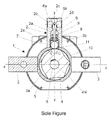
- a fluid control device 1 comprises one or more longitudinal banks (three banks arranged along two axes x-x and y-y extending perpendicular to each other are shown in the drawing) of three-way valve bodies 2 having three ways 2b, 2c and 2d, a valve seat 2a being formed in each valve body.
- the banks or heads of valve bodies are supported by a tubular stator body 3, and radially arranged about a central axis of rotation z-z, the axes x-x and y-y extending perpendicular to, and crossing at, the axis of rotation z-z.
- An axial bore 3a is formed in the tubular stator body 3, and a rotor group comprising a plurality of cam elements 4 is mounted for rotation therein.
- the cam elements 4 are spaced apart from one another, and keyed to a rotor shaft 5 designed to rotate about the axis of rotation z-z.
- the device 1 further comprises at least one valve seat 2a which radially extends along, or parallel to, the axis x-x or y-y.
- a needle valve element 6 is slidingly mounted in each valve seat 2a.
- each valve element 6 has an intercepting conical or frustoconical end portion 6a, which is preferably provided with a sealing O-ring 6b located in a joining zone where the three ways 2b-2d meet, and thus the end portion 6a closes the way 2c when the needle valve 6 is in its extended or working position, whereas it puts the three ways 2b-2d into communication with one another, when it is in its retracted or rest position (as shown in the drawing).
- the other end of the needle valve 6 is in friction engagement with a friction deadening element, preferably a rolling element, e. g. a sphere or a roller 7 free to rotate in a receiving seat 2e delimited in enlarged end of the valve seat 2a, and located in contact with the peripheral edge of a respective cam 4.
- a friction deadening element preferably a rolling element, e. g. a sphere or a roller 7 free to rotate in a receiving seat 2e delimited in enlarged end of the valve seat 2a, and located in contact with the peripheral edge of a respective cam 4.
- Each needle valve element 6 is resiliently loaded at an intermediate section thereof, e. g. by means of one or more helical springs 8 designed to keep it urged against the sphere 7, and is provided with a sealing O-ring 9 at its end portion in order to ensure liquid seal between the three ways 2d-2d and the inner rotor.
- a sleeve insert 10 is arranged, in which a plurality of bores flared towards the respective valve seat and equal in number to the valve seats 2a are formed that are designed to act as bounding element for a respective sphere 7.
- a device may comprise one or more pump units (not shown in the drawing) designed to supply one or more fluids according to a predetermined sequence that is established by the shape of the cam rotor 4, which is driven by suitable driving means, e. g. a program-controlled electric motor (not shown in the drawing).
- suitable driving means e. g. a program-controlled electric motor (not shown in the drawing).
- a device according to the present invention can be advantageously installed in an apparatus as described in the patent application VR2005A000143 referred to above.
- the O-Rings 6b or 9 are made of a perfluorinated compound, such as a perfluorinated fluoro-rubber, e. g. the product FFKM available at FFKM in Hamburg (Germany), or a perfluorinated elastomer, e. g. the product Kaflon obtainable from G.M.I. srl at Cividate al Piano (Bergamo - Italy).
- a perfluorinated compound such as a perfluorinated fluoro-rubber, e. g. the product FFKM available at FFKM in Hamburg (Germany), or a perfluorinated elastomer, e. g. the product Kaflon obtainable from G.M.I. srl at Cividate al Piano (Bergamo - Italy).
- the sphere or roller 7 or a portion thereof can be in a single piece with the needle valve element 6, in which case the valve element would have a rounded end enlargement which would directly slide onto its respective cam element 4 with no rolling friction component between valve and cam elements.
Landscapes
- Mechanically-Actuated Valves (AREA)
- Electrically Driven Valve-Operating Means (AREA)
- Centrifugal Separators (AREA)
- Engine Equipment That Uses Special Cycles (AREA)
- Fluid-Pressure Circuits (AREA)
Applications Claiming Priority (1)
| Application Number | Priority Date | Filing Date | Title |
|---|---|---|---|
| ITVR20070067 ITVR20070067A1 (it) | 2007-05-08 | 2007-05-08 | Dispositivo di intercettazione di fluido |
Publications (1)
| Publication Number | Publication Date |
|---|---|
| EP1990194A2 true EP1990194A2 (de) | 2008-11-12 |
Family
ID=39580292
Family Applications (1)
| Application Number | Title | Priority Date | Filing Date |
|---|---|---|---|
| EP20080155771 Withdrawn EP1990194A2 (de) | 2007-05-08 | 2008-05-07 | Fluidsteuerungsvorrichtung |
Country Status (2)
| Country | Link |
|---|---|
| EP (1) | EP1990194A2 (de) |
| IT (1) | ITVR20070067A1 (de) |
Cited By (1)
| Publication number | Priority date | Publication date | Assignee | Title |
|---|---|---|---|---|
| WO2012058373A2 (en) | 2010-10-27 | 2012-05-03 | Matthews Resources, Inc. | Valve jet printer with inert plunger tip |
-
2007
- 2007-05-08 IT ITVR20070067 patent/ITVR20070067A1/it unknown
-
2008
- 2008-05-07 EP EP20080155771 patent/EP1990194A2/de not_active Withdrawn
Cited By (11)
| Publication number | Priority date | Publication date | Assignee | Title |
|---|---|---|---|---|
| WO2012058373A2 (en) | 2010-10-27 | 2012-05-03 | Matthews Resources, Inc. | Valve jet printer with inert plunger tip |
| WO2012058373A3 (en) * | 2010-10-27 | 2012-07-26 | Matthews Resources, Inc. | Valve jet printer with inert plunger tip |
| US8820871B2 (en) | 2010-10-27 | 2014-09-02 | Matthews Resources, Inc. | Valve jet printer with inert plunger tip |
| US9108424B2 (en) | 2010-10-27 | 2015-08-18 | Matthews Resources, Inc. | Valve jet printer with inert plunger tip |
| US9676184B2 (en) | 2010-10-27 | 2017-06-13 | Matthews Resources, Inc. | Valve jet printer with inert plunger tip |
| EP2632730A4 (de) * | 2010-10-27 | 2018-03-28 | Matthews Resources, Inc. | Ventildüsendrucker mit einer trägen kolbenspitze |
| US10059098B2 (en) | 2010-10-27 | 2018-08-28 | Matthews International Corporation | Valve jet printer with inert plunger tip |
| EP3587121A1 (de) * | 2010-10-27 | 2020-01-01 | Matthews International Corporation | Ventildüsendrucker mit träger kolbenspitze |
| US10532569B2 (en) | 2010-10-27 | 2020-01-14 | Matthews International Corporation | Valve jet printer with inert plunger tip |
| US10864724B2 (en) | 2010-10-27 | 2020-12-15 | Matthews International Corporation | Valve jet printer with inert plunger tip |
| US11840080B2 (en) | 2010-10-27 | 2023-12-12 | Matthews International Corporation | Valve jet printer with inert plunger tip |
Also Published As
| Publication number | Publication date |
|---|---|
| ITVR20070067A1 (it) | 2008-11-09 |
Similar Documents
| Publication | Publication Date | Title |
|---|---|---|
| DE19861466B4 (de) | Ventilzeitsteuervorrichtung | |
| US8746195B2 (en) | Variable valve train for internal combustion engines for actuating gas exchange valves | |
| US20110041681A1 (en) | Positive-displacement machine | |
| EP3693092B1 (de) | Reinigungsmaschine | |
| RU2564155C2 (ru) | Смещенный кулачок для поршневого насоса | |
| WO2016178889A1 (en) | Pneumatic timing valve | |
| US20110200463A1 (en) | Pump, particularly high-pressure fuel pump | |
| KR101110740B1 (ko) | 레이디얼 피스톤 펌프의 피스톤과 편심캠의 구조 | |
| CA2939613C (en) | Machine for preparing liquid products, in particular via capsules | |
| EP3119247B1 (de) | Maschine zur herstellung von flüssigen produkten, insbesondere über kapseln | |
| EP4416416B1 (de) | Antriebsauslöseanordnung für einen drehventilblock und drehventilblock | |
| CN111042982B (zh) | 活塞式反复运动装置 | |
| US20210116048A1 (en) | Non-electric multi-channel valve for aqueous liquids or vapor | |
| US20190353147A1 (en) | Injection pump | |
| CN220267874U (zh) | 具有减少油液回流功能的活塞轴泵 | |
| CN107689304B (zh) | 一种液压操动机构 | |
| JP4894802B2 (ja) | 燃料噴射ポンプ | |
| US2312228A (en) | Pump | |
| KR101691061B1 (ko) | 밸브 조립체 및 이를 구비한 가변오일펌프 시스템 | |
| JPWO2017145353A1 (ja) | 弁システム及び蒸気タービン | |
| WO2006037171A1 (en) | An improved reciprocating pump | |
| CN108026903A (zh) | 高压泵 | |
| RU2636356C1 (ru) | Устройство для ввода жидких реагентов в трубопровод | |
| RU31819U1 (ru) | Регулируемый диафрагменный насос | |
| DE102014222080A1 (de) | Midlock Zentralventil und Nockenwellenversteller |
Legal Events
| Date | Code | Title | Description |
|---|---|---|---|
| PUAI | Public reference made under article 153(3) epc to a published international application that has entered the european phase |
Free format text: ORIGINAL CODE: 0009012 |
|
| AK | Designated contracting states |
Kind code of ref document: A2 Designated state(s): AT BE BG CH CY CZ DE DK EE ES FI FR GB GR HR HU IE IS IT LI LT LU LV MC MT NL NO PL PT RO SE SI SK TR |
|
| AX | Request for extension of the european patent |
Extension state: AL BA MK RS |
|
| STAA | Information on the status of an ep patent application or granted ep patent |
Free format text: STATUS: THE APPLICATION IS DEEMED TO BE WITHDRAWN |
|
| 18D | Application deemed to be withdrawn |
Effective date: 20101201 |