EP1990111B1 - Sand-introducing device using air, and method and apparatus for producing a mold - Google Patents
Sand-introducing device using air, and method and apparatus for producing a mold Download PDFInfo
- Publication number
- EP1990111B1 EP1990111B1 EP08012491A EP08012491A EP1990111B1 EP 1990111 B1 EP1990111 B1 EP 1990111B1 EP 08012491 A EP08012491 A EP 08012491A EP 08012491 A EP08012491 A EP 08012491A EP 1990111 B1 EP1990111 B1 EP 1990111B1
- Authority
- EP
- European Patent Office
- Prior art keywords
- sand
- molding
- introducing
- air
- flasks
- Prior art date
- Legal status (The legal status is an assumption and is not a legal conclusion. Google has not performed a legal analysis and makes no representation as to the accuracy of the status listed.)
- Active
Links
Images


Classifications
-
- B—PERFORMING OPERATIONS; TRANSPORTING
- B22—CASTING; POWDER METALLURGY
- B22C—FOUNDRY MOULDING
- B22C15/00—Moulding machines characterised by the compacting mechanism; Accessories therefor
- B22C15/23—Compacting by gas pressure or vacuum
- B22C15/24—Compacting by gas pressure or vacuum involving blowing devices in which the mould material is supplied in the form of loose particles
-
- B—PERFORMING OPERATIONS; TRANSPORTING
- B22—CASTING; POWDER METALLURGY
- B22C—FOUNDRY MOULDING
- B22C15/00—Moulding machines characterised by the compacting mechanism; Accessories therefor
- B22C15/28—Compacting by different means acting simultaneously or successively, e.g. preliminary blowing and finally pressing
-
- B—PERFORMING OPERATIONS; TRANSPORTING
- B22—CASTING; POWDER METALLURGY
- B22C—FOUNDRY MOULDING
- B22C19/00—Components or accessories for moulding machines
Definitions
- This invention relates to an apparatus for producing a mold according to the preamble of claim 1 and a method therefor.
- JP 2001-259795A which was laid open to the public on September 25, 2001, the applicant proposed an apparatus that can fill a molding space defined by a pattern plate, a flask, a filling frame, and a plurality of squeeze feet appropriately and as required with molding sand by using air.
- the structure of this apparatus is as follows. The apparatus is one to fill a molding space defined by a pattern plate, a flask to be placed on the pattern plate, a filling frame, etc. to be placed on the flask, and the lower part of a sand-filling means, with molding sand by the sand-filling means by using air.
- the sand-filling means has an upper part arranged as a sand tank, a central part arranged as tapered chambers provided with a plurality of porous plates formed with numerous through-holes, and said lower part, which lower part is arranged as nozzles that can advance into the filling frame.
- the apparatus includes means mounted on each of said plurality of porous plates for injecting pressurized air toward the insides of the tapered chambers, and means mounted on the filling frame for controlling the exhaust of air from it.
- the squeeze feet are moved upward or downward so that their squeezing planes are spaced apart by a predetermined distance from the pattern portions of the pattern plate, thereby defining said molding space.
- the molding sand in the tapered chambers is fluidized by appropriately injecting pressurized air from the means for injecting pressurized air, while the amount of the molding sand to be injected from the nozzles of the sand-filling means is increased or decreased, and further, the air to be exhausted from the filling frame is controlled by the means for controlling the exhaust of the air, to decrease or increase the rate of the molding sand to be blown from the nozzles, while the rate of the air to be exhausted from the pattern plate is controlled, thereby locally adjusting the density of the molding sand filled in the molding space.
- EP 1 184 106 A1 discloses a method and a device for filling casting sand.
- the device comprises a pattern plate, a flask, a filling frame and a sand hopper arranged above the pattern plate.
- the sand hopper is provided at its upper, middle and lower portions with a container section for containing the sand.
- a plurality of tapered cavities is defined by a plurality of porous plates and nozzles, which can be inserted into the filling frame.
- the porous plates formed as outer and inner walls are provided with a first and a second air supplying device.
- the sand supplying devices supply compressed air into the tapered cavities, in order to aerate the molding sand and therefore reducing the frictional resistance between the molding sand and the inner walls.
- EP 1 726 382 A1 discloses a method of forming upper and lower molds as well as a device therefore.
- a match plate is put between an upper and a lower flask having intakes for foundry sand.
- An upper and a lower molding space are defined by inserting an upper and a lower squeeze means into openings of an upper and a lower flask.
- the upper and the lower flask and the match plate are rotated and moved so that they become perpendicular and that the intakes of the flasks move upward.
- EP 1 695 776 A1 discloses a method and device for forming a flaskless cope and a drag, and a method of replacing a match plate.
- the present invention has been conceived in view of the circumstances explained above. It is an object of the present invention to provide a molding apparatus and a method, with which even the shaded portions at the reverse of a pattern portion or pattern portions of a match plate are sufficiently filled with molding sand.
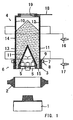
- FIG. 1 An example of a molding apparatus will be now explained by reference to Figs. 1-3 .
- the molding apparatus is arranged, as shown in Figure 1 , so that molding sand is introduced and filled in a molding space defined by a flask 2 and a filling frame 3 to be placed on a pattern plate 1 by a sand-introducing device 4 that uses air.
- a plurality of squeeze feet which can be moved upward and downward, are secured to the bottom of the sand-introducing device 4.
- a plurality of vent plugs are embedded in the pattern plate 1, so that air will be discharged by way of the vent plugs and a space (no reference number assigned) disposed at the bottom of the pattern plate.
- an exhaust-controlling means 6 for controlling the exhaust of the pressurized air from the filling frame 3 is attached to the filling frame 3.
- the exhaust-controlling means 6 comprises a frame member 8 mounted on the periphery of the filling frame 3, for defining a sealed hollow chamber 7 together with the filling frame 3; an on/off valve (not shown) for having the hollow chamber 7 opened or closed to the atmosphere; and many fine apertures 9, 9 formed in the filling frame 3, for discharging the pressurized air through it into the hollow chamber 7.
- the sand-introducing device that uses air includes a body 14 defining a pressure tank of a double-walled structure with the entire wall of the body and two pairs of upper and lower air-permeable porous partitioning plates 10, 11 and defining two, namely, upper and lower, chambers 12, 13, the body further defining at the lower part two (right and left) tapered chambers; sand-introducing ports 15 mounted on the lower end of the body 14, which can advance into the filling frame 3; and two on/off valves 16 and 17, which allow pressurized air sources (not shown) to be in fluid communication with the upper and lower chambers 12 and 13, respectively.
- Each air-permeable porous partitioning plate 10 or 11 is made of a porous resin plate that has many through-holes of an average diameter of 10-500 mm and that has a thickness of 5-20 mm. Each air-permeable porous partitioning plate is attached by means of sealing material. Further, the body 14 is provided with a sand-supplying aperture 19 at the top, which is to be opened or closed by a sliding gate 18.
- the process to introduce and fill a given molding space with molding sand by using air from the stage shown in Figure 1 is now explained.
- the pattern plate 1, the flask 2, etc. are moved upward or downward so that they are placed on one another.
- the filling frame 3 is then moved downward and placed on the flask 2, and the lower part of the sand-introducing device that uses air and the squeeze feet 5, 5 are advanced into the filling frame 3. Further, the squeeze feet 5, are then moved upward or downward so that their squeezing planes are spaced apart by a predetermined distance from the pattern portions of the pattern plate, which portions face the squeeze feet, thereby defining a molding space.
- the on/off valves 16, 17 are opened to supply pressurized air to the chambers 12, 13 to inject it through the air-permeable porous partitioning plates 10, 11 into the inside of the body 14 of the sand-introducing device 4 to fluidize the molding sand in the body 14 and to simultaneously press the upper surface of the molding sand by that injected air. It should be especially noted that since the molding sand in the tapered chambers of the body 14 is fluidized, the resistance of the molding sand in the tapered chambers to their inner surfaces can be reduced.
- the rate that the molding sand is injected from the sand-introducing ports 15, 15 is increased or decreased, while the rate that the air is exhausted through the vent plugs of the pattern plate is controlled.
- the density of the molding sand filled in the molding space can be partially controlled. Accordingly, the molding sand is filled as required, and precisely, in the molding space at all places.
- the directed pressure for the fluidization as in Figures 2 and 3 is for the pressurized air that is to be supplied to the chambers 12, 13 and that is to be injected through the air-permeable porous partitioning plates 10, 11 to fluidize the molding sand in the body 14.
- the measured pressure for the fluidization is that of the pressurized air that is supplied to the chambers 12, 13 and injected through the air-permeable porous partitioning plates 10, 11 into the inside of the body 14 to fluidize the molding sand in the body 14 or that is supplied to the chambers located at the back of the conventional porous plates.
- the measured pressure in the sand tank is that in the body 14 or in the conventional sand tank.
- each plate may be any type of plate that has many through-holes that are smaller than the grain size of the molding sand and that is air-permeable, and that has a desired strength.
- the plate may be a sintered metal plate.
- the structure of the molding apparatus of this example may be that of a conventional molding apparatus for making a flaskless upper mold and a flaskless lower mold.
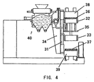
- the molding apparatus includes a pair of flasks, namely, a cope flask 32 and another drag flask 33, which are slidably mounted on a guide rod 31; a flask-moving device 34 for simultaneously moving the flasks between a central molding position where they mate and a spacing position where they are spaced apart; a match plate 35 to be held between the flasks 32 and 33 at the molding position; a pair of squeeze plates 36, 37 to be fittingly inserted in the flasks from their reverse sides; squeeze plate controlling means 38, 39 for Independently setting the shift for each squeeze plate 36 or 37 to be moved in the corresponding flask and for independently controlling the shift of the squeeze plates 36, 37; and a sand-introducing device 40 that uses air for filling the flasks 32, 33 with molding sand, which flasks hold the
- the guide rod 31 is secured to the flask-moving device 34 and is arranged to rotate clockwise 90 deg. with the flask-moving device 34 in a vertical plane from the position shown in Figure 4 . By that rotation, the molding spaces engage with the sand-introducing device 40 through sand-introducing ports (not shown) formed in the flasks 32, 33.
- the sand-introducing device 40 which uses air, can fill with the molding sand the molding spaces defined by the match plate 35, which is used in this example instead of the pattern plate 1, and by the cope and drag flasks 32, 33, and by the pair of squeeze plates 36, 37.
- the match plate 35 which is used in this example instead of the pattern plate 1
- the cope and drag flasks 32, 33 and by the pair of squeeze plates 36, 37.
- Example 2 As in Example 1, the effect of the air-permeable porous partitioning plate of the present invention was confirmed.
- a problem may be caused in that a shaded portion or portions located at the reverse of a pattern portion or portions of the match plate when viewed from the sand-introducing device may not be well filled with the molding sand.
- the molding apparatus of the third example of the present invention that can fill the shaded portions with the molding sand is explained below.
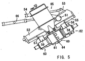
- Figure 5 is a fragmentary, sectional view for schematically showing the molding apparatus of the third example of the present invention for making an upper mold and a lower mold.
- the molding apparatus is similar to the one shown in Figure 4 .
- the main part of the molding apparatus for making an upper mold and a lower mold of this example includes a rotary frame 52 extending laterally and mounted on a supporting shaft 51 that is secured to the base (not shown) of the apparatus, so as to rotate vertically in a vertical plane; a laterally-facing cylinder 54 pivotably mounted on said base (not shown), the distal end of the piston rod of the cylinder being connected to the upper part of the rotary frame 52 (the right end of the rotary frame in Figure 5 ) through a linkage 53 so that it can rotate vertically, the cylinder 54 acting for vertically rotating the rotary frame 52 by its extension and retraction; two spaced-apart guide rods 55, 55 secured to the bottom of the rotary frame 52 and extending alongside the bottom; a pair of opposing flask-
- the sand-introducing device 65 that uses air as in Example 3 may be arranged as a pressure tank structure that uses the porous plates of the sand-introducing device 40 of Example 2.
- the sand-introducing device 65 which uses air, introduces molding sand into the molding spaces defined by inserting the squeeze means 62, 63 into openings of the flasks 60, 61 located opposite those openings of the flasks that are adjacent to the match plate 64 sandwiched by the flasks, the flasks, the match plate, the sand-introducing device 65, etc., are tilted at a desired angle, or they are being tilted.
- the molding sand is easily fluidized in the molding spaces at the shaded portions, thereby enhancing the degree of molding sand filled in the shaded portions.
- the sand-introducing device 65 is arranged as a pressure tank structure that uses special porous plates that are the same as those of the sand-introducing device 40 of Example 2.
- molding sand may be blow-filled in a molding space using a conventional blow-filling method, i.e., by applying pressurized air from above to the surface of the molding sand from a source of pressurized air.
- the present invention is embodied as a molding apparatus that simultaneously produces a flaskless upper mold and a flaskless lower mold
- the molding apparatus may be one that separately produces a flaskless upper mold and a flaskless lower mold, i.e., one that produces one mold.
- the pressurized air is separately supplied in the chambers 12 and 13 by opening the on/off valves 16, 17, the present invention is not limited to that arrangement.
- the chambers 12 and 13 may be combined as one chamber, and thereby only one on/off valve 16 or 17 may be used for supplying pressurized air in the chamber.
Landscapes
- Engineering & Computer Science (AREA)
- Mechanical Engineering (AREA)
- Casting Devices For Molds (AREA)
- Paper (AREA)
- Confectionery (AREA)
Abstract
Description
- This invention relates to an apparatus for producing a mold according to the preamble of
claim 1 and a method therefor. - In
JP 2001-259795A -
EP 1 184 106 A1 -
EP 1 726 382 A1 -
EP 1 695 776 A1 - Using the conventional molding-sand-filling apparatus as explained above may lead to an insufficient filling of a molding space with molding sand, since a shaded portion or portions of the match plate may not be filled sufficiently with molding sand.
- The present invention has been conceived in view of the circumstances explained above. It is an object of the present invention to provide a molding apparatus and a method, with which even the shaded portions at the reverse of a pattern portion or pattern portions of a match plate are sufficiently filled with molding sand.
- This object is solved by a molding apparatus having the features set out in
claim 1 and a method according toclaim 6. - Further preferred embodiments will be apparent from the dependent claims.
-
-
Figure 1 is a schematic sectional view of a device for a tight-flask mold showing the main part of the device. -
Figure 2 is a graph showing the behavior of the pressure of the pressurized air when the molding sand is fluidized in relation to a air-permeable porous partitioning plate used for the device ofFigure 1 . -
Figure 3 is a graph showing the behavior of the pressure of the pressurized air when the molding sand is fluidized when a conventional porous plate is used, which plate has many through-holes, instead of the air-permeable porous partitioning plate used for the device ofFigure 1 . This graph shows a comparison with the graph ofFigure 2 . -
Figure 4 is a fragmentary, sectional view of a device for making a flaskless upper mold and a flaskless lower mold of an embodiment of the present invention, schematically showing the main part of the device. -
Figure 5 is a fragmentary, sectional front view of a device for making a flaskless upper mold and a flaskless lower mold of an embodiment of the present invention, schematically showing the main part of the device. - The embodiments of a sand-introducing device that uses air and a method and an apparatus that uses the sand-introducing device are explained below.
- An example of a molding apparatus will be now explained by reference to
Figs. 1-3 . The molding apparatus is arranged, as shown inFigure 1 , so that molding sand is introduced and filled in a molding space defined by aflask 2 and afilling frame 3 to be placed on apattern plate 1 by a sand-introducingdevice 4 that uses air. A plurality of squeeze feet, which can be moved upward and downward, are secured to the bottom of the sand-introducingdevice 4. - A plurality of vent plugs (not shown) are embedded in the
pattern plate 1, so that air will be discharged by way of the vent plugs and a space (no reference number assigned) disposed at the bottom of the pattern plate. Further, an exhaust-controlling means 6 for controlling the exhaust of the pressurized air from the fillingframe 3 is attached to thefilling frame 3. The exhaust-controllingmeans 6 comprises aframe member 8 mounted on the periphery of thefilling frame 3, for defining a sealedhollow chamber 7 together with thefilling frame 3; an on/off valve (not shown) for having thehollow chamber 7 opened or closed to the atmosphere; and manyfine apertures frame 3, for discharging the pressurized air through it into thehollow chamber 7. - Further, the sand-introducing device that uses air includes a
body 14 defining a pressure tank of a double-walled structure with the entire wall of the body and two pairs of upper and lower air-permeableporous partitioning plates chambers ports 15 mounted on the lower end of thebody 14, which can advance into thefilling frame 3; and two on/offvalves lower chambers porous partitioning plate body 14 is provided with a sand-supplyingaperture 19 at the top, which is to be opened or closed by asliding gate 18. - The process to introduce and fill a given molding space with molding sand by using air from the stage shown in
Figure 1 is now explained. First, by using a known means thepattern plate 1, theflask 2, etc., are moved upward or downward so that they are placed on one another. Thefilling frame 3 is then moved downward and placed on theflask 2, and the lower part of the sand-introducing device that uses air and thesqueeze feet filling frame 3. Further, thesqueeze feet 5, are then moved upward or downward so that their squeezing planes are spaced apart by a predetermined distance from the pattern portions of the pattern plate, which portions face the squeeze feet, thereby defining a molding space. - After the sand-supplying
aperture 19 is closed by thesliding gate 18, the on/offvalves chambers porous partitioning plates body 14 of the sand-introducingdevice 4 to fluidize the molding sand in thebody 14 and to simultaneously press the upper surface of the molding sand by that injected air. It should be especially noted that since the molding sand in the tapered chambers of thebody 14 is fluidized, the resistance of the molding sand in the tapered chambers to their inner surfaces can be reduced. Further, by opening the on/offvalves filling frame 3, the rate that the molding sand is injected from the sand-introducingports - When the pressurized air is supplied, by opening the on/off
valves chambers porous partitioning plates Figure 2 . The behavior of the pressure of the pressurized air when the conventional partitioning plate is used is as shown inFigure 3 . - The directed pressure for the fluidization as in
Figures 2 and3 is for the pressurized air that is to be supplied to thechambers porous partitioning plates body 14. The measured pressure for the fluidization is that of the pressurized air that is supplied to thechambers porous partitioning plates body 14 to fluidize the molding sand in thebody 14 or that is supplied to the chambers located at the back of the conventional porous plates. The measured pressure in the sand tank is that in thebody 14 or in the conventional sand tank. - The graphs of
Figures 2 and3 were compared and analyzed. The measured pressure for the fluidization according toFigure 2 is lower than when a conventional porous plate is used. Thus it is understood that the air-permeableporous partitioning plates - Further, although in Example 1 described above the air-permeable
porous partitioning plates - The molding apparatus of an example of the present invention for a flaskless molding is explained below by reference to
Figure 4 . - The structure of the molding apparatus of this example may be that of a conventional molding apparatus for making a flaskless upper mold and a flaskless lower mold. The molding apparatus includes a pair of flasks, namely, a cope
flask 32 and anotherdrag flask 33, which are slidably mounted on aguide rod 31; a flask-movingdevice 34 for simultaneously moving the flasks between a central molding position where they mate and a spacing position where they are spaced apart; amatch plate 35 to be held between theflasks squeeze plates squeeze plate squeeze plates device 40 that uses air for filling theflasks match plate 35. The sand-introducingdevice 40 may be similar to the sand-introducingdevice 4, which uses air. - By sandwiching the
match plate 35 between the copeflask 32 and thedrag flask 33, and by closing the back openings of theflasks squeeze plates guide rod 31 is secured to the flask-movingdevice 34 and is arranged to rotate clockwise 90 deg. with the flask-movingdevice 34 in a vertical plane from the position shown inFigure 4 . By that rotation, the molding spaces engage with the sand-introducingdevice 40 through sand-introducing ports (not shown) formed in theflasks device 40, which uses air, can fill with the molding sand the molding spaces defined by thematch plate 35, which is used in this example instead of thepattern plate 1, and by the cope and dragflasks squeeze plates Figure 4 of this example, chambers that are similar to thechambers device 4 inFigure 1 , partitioning plates that are similar to the air-permeableporous partitioning plates valves - Again in Example 2, as in Example 1, the effect of the air-permeable porous partitioning plate of the present invention was confirmed.
- In the molding apparatus arranged as explained above for making a flaskless upper mold and a flaskless lower mold, a problem may be caused in that a shaded portion or portions located at the reverse of a pattern portion or portions of the match plate when viewed from the sand-introducing device may not be well filled with the molding sand. Thus, the molding apparatus of the third example of the present invention that can fill the shaded portions with the molding sand is explained below.
-
Figure 5 is a fragmentary, sectional view for schematically showing the molding apparatus of the third example of the present invention for making an upper mold and a lower mold. The molding apparatus is similar to the one shown inFigure 4 . As shown inFigure 5 , the main part of the molding apparatus for making an upper mold and a lower mold of this example includes a rotary frame 52 extending laterally and mounted on a supporting shaft 51 that is secured to the base (not shown) of the apparatus, so as to rotate vertically in a vertical plane; a laterally-facing cylinder 54 pivotably mounted on said base (not shown), the distal end of the piston rod of the cylinder being connected to the upper part of the rotary frame 52 (the right end of the rotary frame inFigure 5 ) through a linkage 53 so that it can rotate vertically, the cylinder 54 acting for vertically rotating the rotary frame 52 by its extension and retraction; two spaced-apart guide rods 55, 55 secured to the bottom of the rotary frame 52 and extending alongside the bottom; a pair of opposing flask-moving members 58, 59 for moving a cope flask and a drag flask, respectively, connected to an upper and a lower guide holder 56, 57 respectively, which holders are in turn slidably mounted on the two respective guide rods 55, 55; a cope flask 60 and a drag flask 61 mounted on the flask-moving members 58 and 59, respectively, the flasks having a sand-introducing ports in its sidewall; squeeze means 62 and 63 mounted on the flask-moving members 58 and 59, respectively, for squeezing molding sand filled in the cope flask 60 and the drag flask 61; a transferable match plate 64 to be disposed and held between the cope flask 60 and the drag flask 61; a sand-introducing device 65 mounted for being vertically rotated in a vertical plane about the rotary frame 52, which device uses air for introducing molding sand through the sand-introducing ports of flasks 60, 61 into molding spaces; another lateral cylinder 66 having a piston rod connected at it's distal end to the sand-introducing device 65, for vertically rotating the sand-introducing device 65 about the rotary frame 52 to allow the sand-introducing device 65 to engage with and to disengage from the sand-introducing ports of the flasks by its extension and retraction. - The sand-introducing
device 65 that uses air as in Example 3 may be arranged as a pressure tank structure that uses the porous plates of the sand-introducingdevice 40 of Example 2. - In the operation of the molding apparatus arranged as explained above, while the sand-introducing
device 65, which uses air, introduces molding sand into the molding spaces defined by inserting the squeeze means 62, 63 into openings of theflasks match plate 64 sandwiched by the flasks, the flasks, the match plate, the sand-introducingdevice 65, etc., are tilted at a desired angle, or they are being tilted. By this, the molding sand is easily fluidized in the molding spaces at the shaded portions, thereby enhancing the degree of molding sand filled in the shaded portions. - The examples explained above are only for exemplification, and it should be understood that the present invention is not limited to them. Clearly, one skilled In the art could modify the examples.
- For example, in Example 3 the sand-introducing
device 65 is arranged as a pressure tank structure that uses special porous plates that are the same as those of the sand-introducingdevice 40 of Example 2. However, instead of that structure, or together with it, molding sand may be blow-filled in a molding space using a conventional blow-filling method, i.e., by applying pressurized air from above to the surface of the molding sand from a source of pressurized air. - Although in Examples 2 and 3 the present invention is embodied as a molding apparatus that simultaneously produces a flaskless upper mold and a flaskless lower mold, the molding apparatus may be one that separately produces a flaskless upper mold and a flaskless lower mold, i.e., one that produces one mold.
- Further, although in the examples of the present invention the pressurized air is separately supplied in the
chambers valves chambers valve
Claims (7)
- A molding apparatus comprising:a rotary frame (52) mounted on a supporting shaft (51), for vertical rotation in a vertical plane;a pair of opposing flasks (60, 61) mounted on the rotary frame (52) each flask having a sand-introducing port in a sidewall thereof;flask-moving means (55, 58, 59) for moving the pair of flasks so that the flasks approach each other and are spaced apart for creating molding spaces and for stripping;a sand-introducing device (65) holding molding sand therein, for Introducing the molding sand in the pair of opposing flasks through the sand-introducing ports thereof; andsqueeze means (62, 63) for defining the molding spaces together with the approaching opposing flasks and a match plate sandwiched therebetween, and for squeezing the molding sand filled In the opposing flaskscharacterized in that the sand introducing device (65) is mounted on a rotary frame (52) such that the molding sand is introduced in the molding spaces while the molding spaces and the sand introducing device (65) are being tilted.
- The molding apparatus of claim 1, including a guide rod (55) secured to the rotary frame and a pair of opposing flask-moving members (58, 59), wherein the pair of the opposing flasks (60, 61) are secured to the flask-moving members.
- The molding apparatus of claim 1 or 2, wherein the sand-introducing device has a body acting as a double-walled pressure tank structure with a wall of the body and an air-permeable porous partitioning plate defining a chamber therebetween, and wherein while the molding sand in the sand-introducing device is fluidized by pressurized air injected from the pressure tank structure through the air-permeable porous partitioning plate, the molding sand is introduced In the molding spaces.
- The molding apparatus of claim 3, wherein the air-permeable porous partitioning plate is a plate made of a porous hydrophobic resin or a porous noncorrosive metal.
- The molding apparatus of any one of claims 1 to 4, wherein the sand-introducing device includes means (16) for supplying pressurized air from above to the molding sand held in the sand-introducing device.
- A method of introducing molding sand from a sand-introducing device (65) in molding spaces defined by a match plate (64) having patterns, and a cope flask (60) and a drag flask (61) through sand-introducing ports formed in the side walls of the cope and drag flasks, characterised in that the molding sand is introduced in the molding spaces while the molding spaces and the sand introducing device (65) are being tilted, or after the molding spaces and the sand introducing device (65) are tilted at an angle relative to a horizontal line so that those portions in the molding spaces that are behind the patterns and shaded when viewed from the sand-introducing device (65), when the cope and drag flasks are arranged in the horizontal line with their sand-introducing ports being located at the top of the flasks (60, 61), are filled with the molding sand.
- The method of claim 6, comprising:moving the cope flask (60) and the drag flask (61) along a guide rod (55) to contact with the match plate (64);rotating the guide rod to tilt the molding space; androtating the sand-introducing device (65) to engage with the sand-introducing ports of the flasks.
Applications Claiming Priority (4)
| Application Number | Priority Date | Filing Date | Title |
|---|---|---|---|
| JP2007006731 | 2007-01-16 | ||
| JP2007030032 | 2007-02-09 | ||
| JP2007131471 | 2007-05-17 | ||
| EP07018622A EP1867410B1 (en) | 2007-01-16 | 2007-09-21 | Sand-introducing device using air, and method and apparatus for producing a mold |
Related Parent Applications (2)
| Application Number | Title | Priority Date | Filing Date |
|---|---|---|---|
| EP07018622.6 Division | 2007-09-21 | ||
| EP07018622A Division EP1867410B1 (en) | 2007-01-16 | 2007-09-21 | Sand-introducing device using air, and method and apparatus for producing a mold |
Publications (2)
| Publication Number | Publication Date |
|---|---|
| EP1990111A1 EP1990111A1 (en) | 2008-11-12 |
| EP1990111B1 true EP1990111B1 (en) | 2012-02-01 |
Family
ID=38617396
Family Applications (2)
| Application Number | Title | Priority Date | Filing Date |
|---|---|---|---|
| EP08012491A Active EP1990111B1 (en) | 2007-01-16 | 2007-09-21 | Sand-introducing device using air, and method and apparatus for producing a mold |
| EP07018622A Active EP1867410B1 (en) | 2007-01-16 | 2007-09-21 | Sand-introducing device using air, and method and apparatus for producing a mold |
Family Applications After (1)
| Application Number | Title | Priority Date | Filing Date |
|---|---|---|---|
| EP07018622A Active EP1867410B1 (en) | 2007-01-16 | 2007-09-21 | Sand-introducing device using air, and method and apparatus for producing a mold |
Country Status (14)
| Country | Link |
|---|---|
| US (2) | US7762307B2 (en) |
| EP (2) | EP1990111B1 (en) |
| JP (1) | JP4548546B2 (en) |
| KR (1) | KR101051515B1 (en) |
| CN (1) | CN101578147B (en) |
| AT (2) | ATE543588T1 (en) |
| BR (2) | BRPI0720975A2 (en) |
| DE (1) | DE602007000843D1 (en) |
| DK (1) | DK1990111T3 (en) |
| EA (1) | EA016210B1 (en) |
| ES (1) | ES2325135T3 (en) |
| MX (1) | MX2009007562A (en) |
| PL (1) | PL1867410T3 (en) |
| WO (1) | WO2008087772A1 (en) |
Families Citing this family (13)
| Publication number | Priority date | Publication date | Assignee | Title |
|---|---|---|---|---|
| EP2193860B1 (en) * | 2008-02-04 | 2014-11-12 | Sintokogio, Ltd. | An apparatus for setting a core in a molding machine, a molding machine and method for setting core |
| BRPI0823144A2 (en) | 2008-10-06 | 2015-06-16 | Disa Ind As | Liner plate for lining molding chambers of molding machines |
| JP5062540B2 (en) * | 2010-01-13 | 2012-10-31 | 新東工業株式会社 | Air supply / exhaust device and supply / exhaust method for sand tank in mold making machine |
| EP2383055B1 (en) | 2010-01-15 | 2014-05-07 | Sintokogio, Ltd. | Flaskless mold forming machine |
| JP5585452B2 (en) * | 2010-03-11 | 2014-09-10 | 新東工業株式会社 | Mold making machine |
| JP4766210B1 (en) * | 2010-05-13 | 2011-09-07 | 新東工業株式会社 | Mold making apparatus and mold making method |
| WO2011142049A1 (en) * | 2010-05-13 | 2011-11-17 | 新東工業株式会社 | Mold molding device and mold molding method |
| JP5510823B2 (en) * | 2010-07-23 | 2014-06-04 | 新東工業株式会社 | Unframed mold making method and unframed mold making apparatus |
| KR101764625B1 (en) * | 2010-07-23 | 2017-08-14 | 신토고교 가부시키가이샤 | Snap flask mold molding method and snap flask mold molding apparatus |
| JP5626639B2 (en) * | 2010-08-09 | 2014-11-19 | 新東工業株式会社 | Mold making method |
| CN103831407B (en) * | 2014-03-07 | 2016-01-20 | 南京亚力电气有限公司 | Pick and place mould laborsaving, cast is easy to horizontal parting removable flask molding machine |
| CN103831403B (en) * | 2014-03-07 | 2016-01-20 | 南京亚力电气有限公司 | Structure is simple, and sandblasting is horizontal parting removable flask molding machine easily |
| KR101652411B1 (en) | 2016-02-24 | 2016-08-30 | (주)중앙 | mold manufacturing equipment with transmission means capable of preventing damage of sand mold |
Family Cites Families (16)
| Publication number | Priority date | Publication date | Assignee | Title |
|---|---|---|---|---|
| US3183570A (en) * | 1960-03-21 | 1965-05-18 | Clarence W Vogt | Compacting equipment |
| US3807483A (en) * | 1971-01-08 | 1974-04-30 | E Buhler | Methods and apparatus for producing sand molds |
| DE3010694A1 (en) * | 1979-03-26 | 1980-10-02 | Acme Cleveland Corp | MOLDING MACHINE |
| JPS5645252A (en) * | 1979-09-17 | 1981-04-24 | Toyoda Autom Loom Works Ltd | Pattern exchanging method in flaskless mold molding machine and its device |
| US4411303A (en) * | 1979-10-01 | 1983-10-25 | Kabushiki Kaisha Toyoda Jidoshokki Seisakusho | Sand mold-producing apparatus |
| JP2772859B2 (en) * | 1990-07-27 | 1998-07-09 | 新東工業株式会社 | Frameless mold making machine |
| JPH09271897A (en) * | 1996-04-05 | 1997-10-21 | Sintokogio Ltd | Method for supplying sand into blow head in blow-in type molding machine |
| JPH1015644A (en) * | 1996-06-28 | 1998-01-20 | Sintokogio Ltd | Sand blowing mechanism in blow molding machine |
| DE69902488T2 (en) * | 1999-02-23 | 2002-12-19 | Disa Industries A/S, Herlev | DEVICE FOR PRODUCING BOXLESS SHAPES |
| JP2001213517A (en) * | 1999-11-24 | 2001-08-07 | Daiichi Shisetsu Kogyo Kk | Plate-like member transfer device |
| US6752196B2 (en) * | 2000-02-17 | 2004-06-22 | Sintokogio, Ltd. | Method and device for filling casting sand |
| JP3441060B2 (en) | 2000-03-17 | 2003-08-25 | 新東工業株式会社 | Method and apparatus for filling casting sand |
| DE60016471T2 (en) * | 2000-11-30 | 2005-11-03 | Disa Industries A/S | WIRE LOADING DEVICE FOR MATCHPLATE CASTING MACHINE |
| JP4203840B2 (en) * | 2001-05-29 | 2009-01-07 | 新東工業株式会社 | Casting sand filling method and apparatus in frameless horizontal split mold making machine |
| TW200536634A (en) | 2003-12-18 | 2005-11-16 | Sintokogio Ltd | Method and device for forming flaskless cope and drag, and method of replacing matchplate |
| KR100898196B1 (en) | 2004-03-18 | 2009-05-18 | 신토고교 가부시키가이샤 | Method of forming molding-flask-less, upper and lower molds and device therefor |
-
2007
- 2007-07-30 US US11/882,057 patent/US7762307B2/en active Active
- 2007-09-21 PL PL07018622T patent/PL1867410T3/en unknown
- 2007-09-21 AT AT08012491T patent/ATE543588T1/en active
- 2007-09-21 DE DE602007000843T patent/DE602007000843D1/en active Active
- 2007-09-21 EP EP08012491A patent/EP1990111B1/en active Active
- 2007-09-21 DK DK08012491.0T patent/DK1990111T3/en active
- 2007-09-21 ES ES07018622T patent/ES2325135T3/en active Active
- 2007-09-21 AT AT07018622T patent/ATE427799T1/en active
- 2007-09-21 EP EP07018622A patent/EP1867410B1/en active Active
- 2007-09-26 JP JP2009524836A patent/JP4548546B2/en active Active
- 2007-09-26 KR KR1020097016744A patent/KR101051515B1/en not_active Expired - Fee Related
- 2007-09-26 EA EA200970689A patent/EA016210B1/en not_active IP Right Cessation
- 2007-09-26 BR BRPI0720975-4A patent/BRPI0720975A2/en active IP Right Grant
- 2007-09-26 MX MX2009007562A patent/MX2009007562A/en active IP Right Grant
- 2007-09-26 WO PCT/JP2007/069322 patent/WO2008087772A1/en not_active Ceased
- 2007-09-26 CN CN2007800497690A patent/CN101578147B/en active Active
- 2007-09-26 BR BR122015026405A patent/BR122015026405B1/en active IP Right Grant
-
2009
- 2009-10-13 US US12/588,337 patent/US7784526B2/en active Active
Also Published As
| Publication number | Publication date |
|---|---|
| US20080169083A1 (en) | 2008-07-17 |
| MX2009007562A (en) | 2009-08-13 |
| PL1867410T3 (en) | 2009-09-30 |
| CN101578147A (en) | 2009-11-11 |
| BRPI0720975A2 (en) | 2014-03-18 |
| BR122015026405B1 (en) | 2016-03-01 |
| JP2010515573A (en) | 2010-05-13 |
| JP4548546B2 (en) | 2010-09-22 |
| EA016210B1 (en) | 2012-03-30 |
| ATE543588T1 (en) | 2012-02-15 |
| DE602007000843D1 (en) | 2009-05-20 |
| US7784526B2 (en) | 2010-08-31 |
| ATE427799T1 (en) | 2009-04-15 |
| US20100032124A1 (en) | 2010-02-11 |
| EA200970689A1 (en) | 2010-04-30 |
| US7762307B2 (en) | 2010-07-27 |
| CN101578147B (en) | 2012-05-09 |
| ES2325135T3 (en) | 2009-08-26 |
| EP1990111A1 (en) | 2008-11-12 |
| DK1990111T3 (en) | 2012-03-26 |
| KR20090104858A (en) | 2009-10-06 |
| WO2008087772A1 (en) | 2008-07-24 |
| KR101051515B1 (en) | 2011-07-22 |
| EP1867410A1 (en) | 2007-12-19 |
| EP1867410B1 (en) | 2009-04-08 |
Similar Documents
| Publication | Publication Date | Title |
|---|---|---|
| EP1867410B1 (en) | Sand-introducing device using air, and method and apparatus for producing a mold | |
| EP2433725B1 (en) | Casting mold molding machine | |
| EP1184106B1 (en) | Method and device for filling casting sand | |
| KR20010092775A (en) | Molding device and molding method of sand mold | |
| CN108367341B (en) | Mold molding machine, sand filling compression unit, and mold molding method | |
| US4744404A (en) | Foundry sand blowing apparatus | |
| KR20220112130A (en) | Core machine sand filler | |
| EP3488945A1 (en) | Mold forming method | |
| EP1964626A1 (en) | Method and device for producing tight-flask molds | |
| CN102905817B (en) | For the method for the die cavity equipment of die set and the volume of change die cavity | |
| JP3119329B2 (en) | Molding method for green sand mold | |
| JP3410434B2 (en) | Method and apparatus for filling casting sand | |
| JPH07185740A (en) | Mold making equipment | |
| JP4096314B2 (en) | Molding method of sand mold with frame | |
| JP3659390B2 (en) | Mold making method and apparatus | |
| JPS6048258B2 (en) | mold making machine | |
| JP2001138010A (en) | Casting sand filling compression method and apparatus, and casting sand projection nozzle | |
| JP2001259795A (en) | Method and apparatus for filling casting sand | |
| JPH04200956A (en) | Method for molding casting mold |
Legal Events
| Date | Code | Title | Description |
|---|---|---|---|
| PUAI | Public reference made under article 153(3) epc to a published international application that has entered the european phase |
Free format text: ORIGINAL CODE: 0009012 |
|
| 17P | Request for examination filed |
Effective date: 20080710 |
|
| AC | Divisional application: reference to earlier application |
Ref document number: 1867410 Country of ref document: EP Kind code of ref document: P |
|
| AK | Designated contracting states |
Kind code of ref document: A1 Designated state(s): AT BE BG CH CY CZ DE DK EE ES FI FR GB GR HU IE IS IT LI LT LU LV MC MT NL PL PT RO SE SI SK TR |
|
| AX | Request for extension of the european patent |
Extension state: AL BA HR MK RS |
|
| 17Q | First examination report despatched |
Effective date: 20090506 |
|
| AKX | Designation fees paid |
Designated state(s): AT BE BG CH CY CZ DE DK EE ES FI FR GB GR HU IE IS IT LI LT LU LV MC MT NL PL PT RO SE SI SK TR |
|
| GRAP | Despatch of communication of intention to grant a patent |
Free format text: ORIGINAL CODE: EPIDOSNIGR1 |
|
| GRAS | Grant fee paid |
Free format text: ORIGINAL CODE: EPIDOSNIGR3 |
|
| GRAA | (expected) grant |
Free format text: ORIGINAL CODE: 0009210 |
|
| AC | Divisional application: reference to earlier application |
Ref document number: 1867410 Country of ref document: EP Kind code of ref document: P |
|
| AK | Designated contracting states |
Kind code of ref document: B1 Designated state(s): AT BE BG CH CY CZ DE DK EE ES FI FR GB GR HU IE IS IT LI LT LU LV MC MT NL PL PT RO SE SI SK TR |
|
| REG | Reference to a national code |
Ref country code: GB Ref legal event code: FG4D |
|
| REG | Reference to a national code |
Ref country code: AT Ref legal event code: REF Ref document number: 543588 Country of ref document: AT Kind code of ref document: T Effective date: 20120215 Ref country code: CH Ref legal event code: EP |
|
| REG | Reference to a national code |
Ref country code: DK Ref legal event code: T3 |
|
| REG | Reference to a national code |
Ref country code: DE Ref legal event code: R096 Ref document number: 602007020534 Country of ref document: DE Effective date: 20120329 |
|
| REG | Reference to a national code |
Ref country code: NL Ref legal event code: VDEP Effective date: 20120201 |
|
| LTIE | Lt: invalidation of european patent or patent extension |
Effective date: 20120201 |
|
| PG25 | Lapsed in a contracting state [announced via postgrant information from national office to epo] |
Ref country code: NL Free format text: LAPSE BECAUSE OF FAILURE TO SUBMIT A TRANSLATION OF THE DESCRIPTION OR TO PAY THE FEE WITHIN THE PRESCRIBED TIME-LIMIT Effective date: 20120201 Ref country code: LT Free format text: LAPSE BECAUSE OF FAILURE TO SUBMIT A TRANSLATION OF THE DESCRIPTION OR TO PAY THE FEE WITHIN THE PRESCRIBED TIME-LIMIT Effective date: 20120201 Ref country code: IS Free format text: LAPSE BECAUSE OF FAILURE TO SUBMIT A TRANSLATION OF THE DESCRIPTION OR TO PAY THE FEE WITHIN THE PRESCRIBED TIME-LIMIT Effective date: 20120601 |
|
| PG25 | Lapsed in a contracting state [announced via postgrant information from national office to epo] |
Ref country code: BE Free format text: LAPSE BECAUSE OF FAILURE TO SUBMIT A TRANSLATION OF THE DESCRIPTION OR TO PAY THE FEE WITHIN THE PRESCRIBED TIME-LIMIT Effective date: 20120201 Ref country code: LV Free format text: LAPSE BECAUSE OF FAILURE TO SUBMIT A TRANSLATION OF THE DESCRIPTION OR TO PAY THE FEE WITHIN THE PRESCRIBED TIME-LIMIT Effective date: 20120201 Ref country code: PT Free format text: LAPSE BECAUSE OF FAILURE TO SUBMIT A TRANSLATION OF THE DESCRIPTION OR TO PAY THE FEE WITHIN THE PRESCRIBED TIME-LIMIT Effective date: 20120601 Ref country code: FI Free format text: LAPSE BECAUSE OF FAILURE TO SUBMIT A TRANSLATION OF THE DESCRIPTION OR TO PAY THE FEE WITHIN THE PRESCRIBED TIME-LIMIT Effective date: 20120201 Ref country code: PL Free format text: LAPSE BECAUSE OF FAILURE TO SUBMIT A TRANSLATION OF THE DESCRIPTION OR TO PAY THE FEE WITHIN THE PRESCRIBED TIME-LIMIT Effective date: 20120201 Ref country code: GR Free format text: LAPSE BECAUSE OF FAILURE TO SUBMIT A TRANSLATION OF THE DESCRIPTION OR TO PAY THE FEE WITHIN THE PRESCRIBED TIME-LIMIT Effective date: 20120502 |
|
| REG | Reference to a national code |
Ref country code: AT Ref legal event code: MK05 Ref document number: 543588 Country of ref document: AT Kind code of ref document: T Effective date: 20120201 |
|
| PG25 | Lapsed in a contracting state [announced via postgrant information from national office to epo] |
Ref country code: CY Free format text: LAPSE BECAUSE OF FAILURE TO SUBMIT A TRANSLATION OF THE DESCRIPTION OR TO PAY THE FEE WITHIN THE PRESCRIBED TIME-LIMIT Effective date: 20120201 |
|
| PG25 | Lapsed in a contracting state [announced via postgrant information from national office to epo] |
Ref country code: CZ Free format text: LAPSE BECAUSE OF FAILURE TO SUBMIT A TRANSLATION OF THE DESCRIPTION OR TO PAY THE FEE WITHIN THE PRESCRIBED TIME-LIMIT Effective date: 20120201 Ref country code: SI Free format text: LAPSE BECAUSE OF FAILURE TO SUBMIT A TRANSLATION OF THE DESCRIPTION OR TO PAY THE FEE WITHIN THE PRESCRIBED TIME-LIMIT Effective date: 20120201 Ref country code: RO Free format text: LAPSE BECAUSE OF FAILURE TO SUBMIT A TRANSLATION OF THE DESCRIPTION OR TO PAY THE FEE WITHIN THE PRESCRIBED TIME-LIMIT Effective date: 20120201 Ref country code: EE Free format text: LAPSE BECAUSE OF FAILURE TO SUBMIT A TRANSLATION OF THE DESCRIPTION OR TO PAY THE FEE WITHIN THE PRESCRIBED TIME-LIMIT Effective date: 20120201 Ref country code: SE Free format text: LAPSE BECAUSE OF FAILURE TO SUBMIT A TRANSLATION OF THE DESCRIPTION OR TO PAY THE FEE WITHIN THE PRESCRIBED TIME-LIMIT Effective date: 20120201 |
|
| PG25 | Lapsed in a contracting state [announced via postgrant information from national office to epo] |
Ref country code: IT Free format text: LAPSE BECAUSE OF FAILURE TO SUBMIT A TRANSLATION OF THE DESCRIPTION OR TO PAY THE FEE WITHIN THE PRESCRIBED TIME-LIMIT Effective date: 20120201 Ref country code: SK Free format text: LAPSE BECAUSE OF FAILURE TO SUBMIT A TRANSLATION OF THE DESCRIPTION OR TO PAY THE FEE WITHIN THE PRESCRIBED TIME-LIMIT Effective date: 20120201 |
|
| PLBE | No opposition filed within time limit |
Free format text: ORIGINAL CODE: 0009261 |
|
| STAA | Information on the status of an ep patent application or granted ep patent |
Free format text: STATUS: NO OPPOSITION FILED WITHIN TIME LIMIT |
|
| 26N | No opposition filed |
Effective date: 20121105 |
|
| PG25 | Lapsed in a contracting state [announced via postgrant information from national office to epo] |
Ref country code: AT Free format text: LAPSE BECAUSE OF FAILURE TO SUBMIT A TRANSLATION OF THE DESCRIPTION OR TO PAY THE FEE WITHIN THE PRESCRIBED TIME-LIMIT Effective date: 20120201 |
|
| REG | Reference to a national code |
Ref country code: DE Ref legal event code: R097 Ref document number: 602007020534 Country of ref document: DE Effective date: 20121105 |
|
| PG25 | Lapsed in a contracting state [announced via postgrant information from national office to epo] |
Ref country code: MC Free format text: LAPSE BECAUSE OF NON-PAYMENT OF DUE FEES Effective date: 20120930 Ref country code: ES Free format text: LAPSE BECAUSE OF FAILURE TO SUBMIT A TRANSLATION OF THE DESCRIPTION OR TO PAY THE FEE WITHIN THE PRESCRIBED TIME-LIMIT Effective date: 20120512 |
|
| REG | Reference to a national code |
Ref country code: CH Ref legal event code: PL |
|
| GBPC | Gb: european patent ceased through non-payment of renewal fee |
Effective date: 20120921 |
|
| REG | Reference to a national code |
Ref country code: IE Ref legal event code: MM4A |
|
| REG | Reference to a national code |
Ref country code: FR Ref legal event code: ST Effective date: 20130531 |
|
| PG25 | Lapsed in a contracting state [announced via postgrant information from national office to epo] |
Ref country code: CH Free format text: LAPSE BECAUSE OF NON-PAYMENT OF DUE FEES Effective date: 20120930 Ref country code: BG Free format text: LAPSE BECAUSE OF FAILURE TO SUBMIT A TRANSLATION OF THE DESCRIPTION OR TO PAY THE FEE WITHIN THE PRESCRIBED TIME-LIMIT Effective date: 20120501 Ref country code: LI Free format text: LAPSE BECAUSE OF NON-PAYMENT OF DUE FEES Effective date: 20120930 Ref country code: GB Free format text: LAPSE BECAUSE OF NON-PAYMENT OF DUE FEES Effective date: 20120921 Ref country code: IE Free format text: LAPSE BECAUSE OF NON-PAYMENT OF DUE FEES Effective date: 20120921 |
|
| PG25 | Lapsed in a contracting state [announced via postgrant information from national office to epo] |
Ref country code: FR Free format text: LAPSE BECAUSE OF NON-PAYMENT OF DUE FEES Effective date: 20121001 |
|
| PG25 | Lapsed in a contracting state [announced via postgrant information from national office to epo] |
Ref country code: MT Free format text: LAPSE BECAUSE OF FAILURE TO SUBMIT A TRANSLATION OF THE DESCRIPTION OR TO PAY THE FEE WITHIN THE PRESCRIBED TIME-LIMIT Effective date: 20120201 |
|
| PG25 | Lapsed in a contracting state [announced via postgrant information from national office to epo] |
Ref country code: TR Free format text: LAPSE BECAUSE OF FAILURE TO SUBMIT A TRANSLATION OF THE DESCRIPTION OR TO PAY THE FEE WITHIN THE PRESCRIBED TIME-LIMIT Effective date: 20120201 |
|
| PG25 | Lapsed in a contracting state [announced via postgrant information from national office to epo] |
Ref country code: LU Free format text: LAPSE BECAUSE OF NON-PAYMENT OF DUE FEES Effective date: 20120921 |
|
| PG25 | Lapsed in a contracting state [announced via postgrant information from national office to epo] |
Ref country code: HU Free format text: LAPSE BECAUSE OF FAILURE TO SUBMIT A TRANSLATION OF THE DESCRIPTION OR TO PAY THE FEE WITHIN THE PRESCRIBED TIME-LIMIT Effective date: 20070921 |
|
| PGFP | Annual fee paid to national office [announced via postgrant information from national office to epo] |
Ref country code: DK Payment date: 20230925 Year of fee payment: 17 |
|
| REG | Reference to a national code |
Ref country code: DK Ref legal event code: EBP Effective date: 20240930 |
|
| PG25 | Lapsed in a contracting state [announced via postgrant information from national office to epo] |
Ref country code: DK Free format text: LAPSE BECAUSE OF NON-PAYMENT OF DUE FEES Effective date: 20240930 |
|
| PGFP | Annual fee paid to national office [announced via postgrant information from national office to epo] |
Ref country code: DE Payment date: 20250919 Year of fee payment: 19 |