EP1989980A1 - Kitchen robot having a movable drive unit - Google Patents
Kitchen robot having a movable drive unit Download PDFInfo
- Publication number
- EP1989980A1 EP1989980A1 EP07404001A EP07404001A EP1989980A1 EP 1989980 A1 EP1989980 A1 EP 1989980A1 EP 07404001 A EP07404001 A EP 07404001A EP 07404001 A EP07404001 A EP 07404001A EP 1989980 A1 EP1989980 A1 EP 1989980A1
- Authority
- EP
- European Patent Office
- Prior art keywords
- drive unit
- robot
- container
- movable
- blender
- Prior art date
- Legal status (The legal status is an assumption and is not a legal conclusion. Google has not performed a legal analysis and makes no representation as to the accuracy of the status listed.)
- Withdrawn
Links
Images


Classifications
-
- A—HUMAN NECESSITIES
- A47—FURNITURE; DOMESTIC ARTICLES OR APPLIANCES; COFFEE MILLS; SPICE MILLS; SUCTION CLEANERS IN GENERAL
- A47J—KITCHEN EQUIPMENT; COFFEE MILLS; SPICE MILLS; APPARATUS FOR MAKING BEVERAGES
- A47J43/00—Implements for preparing or holding food, not provided for in other groups of this subclass
- A47J43/04—Machines for domestic use not covered elsewhere, e.g. for grinding, mixing, stirring, kneading, emulsifying, whipping or beating foodstuffs, e.g. power-driven
- A47J43/07—Parts or details, e.g. mixing tools, whipping tools
- A47J43/08—Driving mechanisms
- A47J43/082—Driving mechanisms for machines with tools driven from the upper side
-
- A—HUMAN NECESSITIES
- A47—FURNITURE; DOMESTIC ARTICLES OR APPLIANCES; COFFEE MILLS; SPICE MILLS; SUCTION CLEANERS IN GENERAL
- A47J—KITCHEN EQUIPMENT; COFFEE MILLS; SPICE MILLS; APPARATUS FOR MAKING BEVERAGES
- A47J43/00—Implements for preparing or holding food, not provided for in other groups of this subclass
- A47J43/04—Machines for domestic use not covered elsewhere, e.g. for grinding, mixing, stirring, kneading, emulsifying, whipping or beating foodstuffs, e.g. power-driven
- A47J43/044—Machines for domestic use not covered elsewhere, e.g. for grinding, mixing, stirring, kneading, emulsifying, whipping or beating foodstuffs, e.g. power-driven with tools driven from the top side
- A47J2043/04454—Apparatus of counter top type
- A47J2043/04481—Apparatus of counter top type with a mixing unit pivotable on the support
Landscapes
- Engineering & Computer Science (AREA)
- Mechanical Engineering (AREA)
- Food Science & Technology (AREA)
- Food-Manufacturing Devices (AREA)
Abstract
Present invention is related to the use of a drive unit (2) that is movable in vertical and horizontal/circular directions automatically and in a combined way via a locking switch (1) located thereon and equipped with outlet shaft having a main motor and a motion transfer mechanism, and a motor actuating/speed adjusting electronic arrangement control switch (3), in the devices for food preparation, i.e. in the kitchen robots.
Description
- Present invention is related to the use of a drive unit (2) that is movable in vertical and horizontal/circular directions automatically and in a combined way via a locking switch (1) located thereon and equipped with outlet shaft (8) having a main motor (10) and a motion transfer mechanism (11), and a motor actuating/speed adjusting electronic arrangement control switch (3), in the devices for food preparation, i.e. in the kitchen robots.
- It is easier to use than the traditional kitchen robots available at the market and also it is possible to use those units made of glass.
- This invention, as different from the traditional kitchen robots, has a movable drive unit (2) disposed in the robot body (6) and thus ensures all food preparation actions, such as food cutting, ice breaking, meat mincing, dough kneading, egg beating with a mixer apparatus, cake holding, squeezing rigid fruits and vegetables, orange squeezing, grating, mixing juices, potato slicing, cheese grating, etc. either in the robot container (4) or in the blender container (5).
- In this invention, one of the work accessories (9) (cutting/slicing/smashing) required is located in the robot container or blender while the kitchen robot is standstill, the lids (12) are closed appropriately.
- The upper handle (7) on work accessories (9) such as cutting/slicing etc., always remains in the middle of the lid (12) and outside in a ready position. Movable drive unit (2) is rotated up to 90° until aligns with the robot container (4) or blender container (5) handle (7) and drive unit (2) handle (8) (also the outlet shaft) at the rotation axis (13). When the handles (7-8) get aligned, drive unit (2) is manually pushed down and the drive unit (2) is caused to be fixed on the locks (14) over the main body (6). In this position the accessory handle (7) and power unit handle / outlet shaft (8) of the device fully grabs each other and are ready for power transfer. Food preparation processes are being started by the command switch (3) of the device. When the process is over, lock switch is (1) pressed and drive unit (2) automatically arises via spring force and releases the robot container (4) or the blender container (5).
- Within the invention, by rotating the movable drive unit up to 90° and circularly over a kitchen robot container (4) or an accessory (9) in a blender container (5) that is ready to operate and by pressing manually in vertical course, it's being locked to the body via the locks (14) and by power transfer to the accessory (9), and the motor (10) is actuated via the electronic arrangement switch.
- In this invention, the movable drive unit (2) is located on the kitchen robot (4) or the accessory in the blender container (5) that is ready for operation with a circular and a rotational movement up to 90 degrees, and pushed manually, locked to the body and attached to the accessory and the motor is actuated with the electronic arrangement switch. Drive group outlet gear (female/male) is centered onto the male/female clutch provided at the top of cutter/breaker apparatus in vessel and thus drives the same.
- In the conventional method, the engine, belt/pulley and/or gear system transfer units are fixed, process vessels are placed on the outlet axis that is fixed and process is started.
- In this patent, the main body of the robot constitutes a seat for vessel/blender vessel, and there is no power outlet unit located from below. The vessel seat in the main body acts to fix the vessels in position in order to ensure that the outlet axis is received by the movable drive group above the vessel.
- Main body ensures that movable drive group is placed in an appropriate position with respect to vessels and has a seat which allows that movable mechanisms of the drive group opens and closes with a vertical/ circular combined movement with spiral actions in a safe manner.
- Drive group comprises an engine, transfer units, outlet gear and a safety switch, and multiple plastic components that maintain them as a single unit. Drive unit is placed into main body that contains spiral female/ male seats. A spring is provided at the vertical axis between main body and drive group. When drive group's lock is opened manually, spring comes over the total weight of drive group with a predetermined spring push force and ensures that drive group is moved in vertical direction. When the male/female pins on drive group move in the spiral male/female seats on main body, a vertical spring force causes drive group to move in a combined way, both in vertical direction and circular orientation up to 90 degrees with respect to vertical axis. Thereby the outlet gear provided on the drive group may easily open and close over the vessels with a circular/ vertical movement. The engine in moveable drive group is supplied power through a power cable that is located on main body in a way to ensure that it is not damaged during vertical/circular movement.
- In this invention, one of the work accessories (cutting/slicing/smashing/mixing/dough conditioning/rigid fruit or vegetable squeezing) required is located in the robot container or blender while the kitchen robot is standstill, the lids are closed appropriately, and the drive unit is made ready to operate by being rotationally moved and fitted over the seat on the lid.
- In this invention, the switch disposed on the movable drive unit is only movable after the motor is completely stopped, and moved first in vertical, then in circular directions to release the working container (robot container or blender).
-
- 1) It is very easier to use than the traditional kitchen robots.
- 2) In this invention, the movable (not stationary) drive unit drives the work accessories in the robot container from above (no funnel present in the robot container).
- 3) In this invention, the movable drive unit drives the work accessories in the blender container disposed in the place of robot container.
- 4) In this invention, all safety rules are duly observed since either the robot container or the blender container is forcefully covered by the drive unit located on the lid during operation.
- 5) As a result of the arrangement of this invention, a robot container made of glass or a blender container made of glass can be used, which is impossible with the traditional robots.
- 6) As a result of the arrangement of this invention, a kitchen robot having a movable drive unit, can have a blender container or robot container, made of both glass, plastics and stainless steel.
-
-
Figure 1 : General view of the kitchen robot from up (movable drive unit is open) -
Figure 2 : General view of the kitchen robot from up (movable drive unit is closed) -
Figure 3 :- (2) Movable drive unit
- (3) Electronic arrangement control switch
- (1) Locking switch
- (14) Locks
- (6) Robot Body
- (12) Lids
- (4) Kitchen Robot container
-
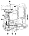
Figure 4 : Close mode- (1) Locking switch
- (10) Motor
- (13) Rotation axis
- (2) Movable drive unit
- (11) Motion transfer mechanism
- (8) Outlet shaft
- (7) Handle
- (9) Accessory
- (12) Lids
-
Figure 5 : Open mode- (10) Motor
- (8) Outlet shaft
- (7) Handle
- (9) Accessory
- (12) Lids
- (4) Kitchen robot container
Claims (4)
- The use of a drive unit (2) that is movable in vertical and horizontal/circular directions automatical and in a combined way via a locking switch (1) located thereon and equipped with outlet shaft having a main motor and a motion transfer mechanism, and a motor actuating/speed adjusting electronic arrangement control switch (3), in the devices for food preparation, i.e. in the kitchen robots, characterized in that it has a movable drive unit disposed in the robot body (6) and thus ensures all food preparation actions, such as food cutting, ice breaking, meat mincing, dough kneading, egg beating with a mixer apparatus, cake holding, squeezing rigid fruits and vegetables, orange squeezing, grating, mixing juices, potato slicing, cheese grating, etc. either in the robot container (4) or in the blender container (5).
- The use according to claim 1, wherein one of the work accessories (cutting/slicing/smashing/mixing/dough conditioning/rigid fruit or vegetable squeezing) required is located in the robot container or blender while the kitchen robot is standstill, the lids are closed appropriately and the device is prepared for functioning by moving the drive unit circularly and fitting it in its seat on the lid.
- This invention is according to claim 1 wherein an outlet gear/clutch of a drive unit is positioned onto the top gear/clutch of a cutter/breaker accessory in the kitchen robot vessel/blender vessel that is ready to operate, with a circular rotational movement up to 90 degrees, and drive group is directed downwards manually overcoming the spring force between drive group and main body to fit the drive group in the locks provided in the main body, thereby engine is actuated safely with an electronic arrangement button.
- The invention according to claim 1, wherein the switch disposed on the movable drive unit is only movable after the motor is completely stopped, and moved first in vertical, then in circular directions to release the working container (robot container or blender).
Priority Applications (1)
| Application Number | Priority Date | Filing Date | Title |
|---|---|---|---|
| EP07404001A EP1989980A1 (en) | 2007-05-11 | 2007-05-11 | Kitchen robot having a movable drive unit |
Applications Claiming Priority (1)
| Application Number | Priority Date | Filing Date | Title |
|---|---|---|---|
| EP07404001A EP1989980A1 (en) | 2007-05-11 | 2007-05-11 | Kitchen robot having a movable drive unit |
Publications (1)
| Publication Number | Publication Date |
|---|---|
| EP1989980A1 true EP1989980A1 (en) | 2008-11-12 |
Family
ID=38520129
Family Applications (1)
| Application Number | Title | Priority Date | Filing Date |
|---|---|---|---|
| EP07404001A Withdrawn EP1989980A1 (en) | 2007-05-11 | 2007-05-11 | Kitchen robot having a movable drive unit |
Country Status (1)
| Country | Link |
|---|---|
| EP (1) | EP1989980A1 (en) |
Cited By (5)
| Publication number | Priority date | Publication date | Assignee | Title |
|---|---|---|---|---|
| CN104720550A (en) * | 2014-04-10 | 2015-06-24 | 金再垣 | Juicer powered on the top |
| EP2956041A2 (en) * | 2013-02-15 | 2015-12-23 | Jochen Mertens | Mixer having measures for reducing the input of air oxygen into the mixer contents |
| WO2019023583A1 (en) * | 2017-07-28 | 2019-01-31 | Nuro, Inc. | Fleet of robot vehicles for food product preparation |
| CN113618794A (en) * | 2021-07-26 | 2021-11-09 | 谢小妹 | Food processing is used for making fruit cheese machine |
| US11907887B2 (en) | 2020-03-23 | 2024-02-20 | Nuro, Inc. | Methods and apparatus for unattended deliveries |
Citations (5)
| Publication number | Priority date | Publication date | Assignee | Title |
|---|---|---|---|---|
| US2570358A (en) * | 1948-04-22 | 1951-10-09 | Dormeyer Corp | Food mixer indexing mechanism |
| DE850933C (en) * | 1950-12-03 | 1952-09-29 | Reform Maschinenfabrik Paul Pa | Electrically powered kitchen machine |
| DE3323529A1 (en) * | 1983-06-30 | 1985-01-10 | Robert Krups Stiftung & Co KG, 5650 Solingen | Multi-purpose kitchen machine |
| US5524530A (en) * | 1994-02-07 | 1996-06-11 | U.S. Philips Corporation | Kitchen machine with protected rotatable bowl |
| EP1621117A1 (en) * | 2004-07-29 | 2006-02-01 | Erna-Mas Makina Ticaret Ve Sanayi A.S. | Kitchen robot |
-
2007
- 2007-05-11 EP EP07404001A patent/EP1989980A1/en not_active Withdrawn
Patent Citations (5)
| Publication number | Priority date | Publication date | Assignee | Title |
|---|---|---|---|---|
| US2570358A (en) * | 1948-04-22 | 1951-10-09 | Dormeyer Corp | Food mixer indexing mechanism |
| DE850933C (en) * | 1950-12-03 | 1952-09-29 | Reform Maschinenfabrik Paul Pa | Electrically powered kitchen machine |
| DE3323529A1 (en) * | 1983-06-30 | 1985-01-10 | Robert Krups Stiftung & Co KG, 5650 Solingen | Multi-purpose kitchen machine |
| US5524530A (en) * | 1994-02-07 | 1996-06-11 | U.S. Philips Corporation | Kitchen machine with protected rotatable bowl |
| EP1621117A1 (en) * | 2004-07-29 | 2006-02-01 | Erna-Mas Makina Ticaret Ve Sanayi A.S. | Kitchen robot |
Cited By (10)
| Publication number | Priority date | Publication date | Assignee | Title |
|---|---|---|---|---|
| EP2956041A2 (en) * | 2013-02-15 | 2015-12-23 | Jochen Mertens | Mixer having measures for reducing the input of air oxygen into the mixer contents |
| CN104720550A (en) * | 2014-04-10 | 2015-06-24 | 金再垣 | Juicer powered on the top |
| US20170027364A1 (en) * | 2014-04-10 | 2017-02-02 | Jae Won Kim | Upper powered type juice squeezing extractor |
| EP3130261A4 (en) * | 2014-04-10 | 2018-01-10 | Kim, Jae-Won | Top drive type juicer |
| CN109330340A (en) * | 2014-04-10 | 2019-02-15 | 金再垣 | Top energization juice extractor |
| CN109330340B (en) * | 2014-04-10 | 2021-01-29 | 金再垣 | Juicer powered on upper part |
| WO2019023583A1 (en) * | 2017-07-28 | 2019-01-31 | Nuro, Inc. | Fleet of robot vehicles for food product preparation |
| US10332065B2 (en) | 2017-07-28 | 2019-06-25 | Nuro, Inc. | Fleet of robot vehicles for food product preparation |
| US11907887B2 (en) | 2020-03-23 | 2024-02-20 | Nuro, Inc. | Methods and apparatus for unattended deliveries |
| CN113618794A (en) * | 2021-07-26 | 2021-11-09 | 谢小妹 | Food processing is used for making fruit cheese machine |
Similar Documents
| Publication | Publication Date | Title |
|---|---|---|
| US9167938B2 (en) | Food processor mixer attachment | |
| US9192264B2 (en) | Food processor | |
| AU2013280314B2 (en) | Blender with elevator assembly and removable spindle | |
| US9375689B2 (en) | Machine for the treatment of food mixtures having scraping and mixing blades and a blender disposed parallel thereto | |
| US8944357B2 (en) | Multifunctional food processing tool for use with a food processing device | |
| EP1989980A1 (en) | Kitchen robot having a movable drive unit | |
| US9386882B2 (en) | Compact blender for frozen beverages | |
| US9420917B2 (en) | Method for blending food or beverages | |
| US20130344220A1 (en) | Removable cupholder for compact blender | |
| CN107427157B (en) | Food processor | |
| RU2020138764A (en) | KITCHEN DEVICE, KITCHEN PROCESSOR AND SAFETY LOCK | |
| US20130343150A1 (en) | Removable blender spindle with container cover | |
| US10349781B2 (en) | Rotor having freewheel | |
| US9370278B1 (en) | Processing system for preparing salad | |
| EP1621117A1 (en) | Kitchen robot | |
| CN110477773B (en) | Efficient wall breaking method | |
| GB2217802A (en) | Multi-purpose kitchen machine | |
| CN110538703B (en) | Wall breaking machine | |
| KR101717011B1 (en) | Mixer composite apparatus | |
| EP2863783B1 (en) | Blender with elevator assembly and removable spindle |
Legal Events
| Date | Code | Title | Description |
|---|---|---|---|
| PUAI | Public reference made under article 153(3) epc to a published international application that has entered the european phase |
Free format text: ORIGINAL CODE: 0009012 |
|
| AK | Designated contracting states |
Kind code of ref document: A1 Designated state(s): AT BE BG CH CY CZ DE DK EE ES FI FR GB GR HU IE IS IT LI LT LU LV MC MT NL PL PT RO SE SI SK TR |
|
| AX | Request for extension of the european patent |
Extension state: AL BA HR MK RS |
|
| AKX | Designation fees paid | ||
| REG | Reference to a national code |
Ref country code: DE Ref legal event code: 8566 |
|
| STAA | Information on the status of an ep patent application or granted ep patent |
Free format text: STATUS: THE APPLICATION IS DEEMED TO BE WITHDRAWN |
|
| 18D | Application deemed to be withdrawn |
Effective date: 20090513 |