EP1989101B1 - Druckaktivierte verriegelung - Google Patents
Druckaktivierte verriegelung Download PDFInfo
- Publication number
- EP1989101B1 EP1989101B1 EP07751364.6A EP07751364A EP1989101B1 EP 1989101 B1 EP1989101 B1 EP 1989101B1 EP 07751364 A EP07751364 A EP 07751364A EP 1989101 B1 EP1989101 B1 EP 1989101B1
- Authority
- EP
- European Patent Office
- Prior art keywords
- latch
- pressure activated
- fluid
- pin
- latch pin
- Prior art date
- Legal status (The legal status is an assumption and is not a legal conclusion. Google has not performed a legal analysis and makes no representation as to the accuracy of the status listed.)
- Active
Links
- 239000012530 fluid Substances 0.000 claims description 77
- 238000005188 flotation Methods 0.000 claims description 22
- 238000004891 communication Methods 0.000 claims description 17
- 238000007789 sealing Methods 0.000 claims description 16
- 239000007789 gas Substances 0.000 description 9
- 230000004913 activation Effects 0.000 description 4
- IJGRMHOSHXDMSA-UHFFFAOYSA-N Atomic nitrogen Chemical compound N#N IJGRMHOSHXDMSA-UHFFFAOYSA-N 0.000 description 2
- 230000000712 assembly Effects 0.000 description 2
- 238000000429 assembly Methods 0.000 description 2
- 230000006835 compression Effects 0.000 description 2
- 238000007906 compression Methods 0.000 description 2
- 238000000034 method Methods 0.000 description 2
- 238000013519 translation Methods 0.000 description 2
- 238000009434 installation Methods 0.000 description 1
- 238000012423 maintenance Methods 0.000 description 1
- 229910052757 nitrogen Inorganic materials 0.000 description 1
- 238000012552 review Methods 0.000 description 1
- 230000009466 transformation Effects 0.000 description 1
- XLYOFNOQVPJJNP-UHFFFAOYSA-N water Substances O XLYOFNOQVPJJNP-UHFFFAOYSA-N 0.000 description 1
Images


Classifications
-
- B—PERFORMING OPERATIONS; TRANSPORTING
- B64—AIRCRAFT; AVIATION; COSMONAUTICS
- B64C—AEROPLANES; HELICOPTERS
- B64C1/00—Fuselages; Constructional features common to fuselages, wings, stabilising surfaces or the like
- B64C1/14—Windows; Doors; Hatch covers or access panels; Surrounding frame structures; Canopies; Windscreens accessories therefor, e.g. pressure sensors, water deflectors, hinges, seals, handles, latches, windscreen wipers
- B64C1/1407—Doors; surrounding frames
- B64C1/1415—Cargo doors, e.g. incorporating ramps
-
- E—FIXED CONSTRUCTIONS
- E05—LOCKS; KEYS; WINDOW OR DOOR FITTINGS; SAFES
- E05B—LOCKS; ACCESSORIES THEREFOR; HANDCUFFS
- E05B47/00—Operating or controlling locks or other fastening devices by electric or magnetic means
- E05B47/0038—Operating or controlling locks or other fastening devices by electric or magnetic means using permanent magnets
-
- E—FIXED CONSTRUCTIONS
- E05—LOCKS; KEYS; WINDOW OR DOOR FITTINGS; SAFES
- E05B—LOCKS; ACCESSORIES THEREFOR; HANDCUFFS
- E05B51/00—Operating or controlling locks or other fastening devices by other non-mechanical means
- E05B51/02—Operating or controlling locks or other fastening devices by other non-mechanical means by pneumatic or hydraulic means
-
- Y—GENERAL TAGGING OF NEW TECHNOLOGICAL DEVELOPMENTS; GENERAL TAGGING OF CROSS-SECTIONAL TECHNOLOGIES SPANNING OVER SEVERAL SECTIONS OF THE IPC; TECHNICAL SUBJECTS COVERED BY FORMER USPC CROSS-REFERENCE ART COLLECTIONS [XRACs] AND DIGESTS
- Y10—TECHNICAL SUBJECTS COVERED BY FORMER USPC
- Y10T—TECHNICAL SUBJECTS COVERED BY FORMER US CLASSIFICATION
- Y10T292/00—Closure fasteners
- Y10T292/08—Bolts
- Y10T292/096—Sliding
- Y10T292/0969—Spring projected
- Y10T292/097—Operating means
-
- Y—GENERAL TAGGING OF NEW TECHNOLOGICAL DEVELOPMENTS; GENERAL TAGGING OF CROSS-SECTIONAL TECHNOLOGIES SPANNING OVER SEVERAL SECTIONS OF THE IPC; TECHNICAL SUBJECTS COVERED BY FORMER USPC CROSS-REFERENCE ART COLLECTIONS [XRACs] AND DIGESTS
- Y10—TECHNICAL SUBJECTS COVERED BY FORMER USPC
- Y10T—TECHNICAL SUBJECTS COVERED BY FORMER US CLASSIFICATION
- Y10T292/00—Closure fasteners
- Y10T292/08—Bolts
- Y10T292/096—Sliding
- Y10T292/1014—Operating means
- Y10T292/1021—Motor
Definitions
- the present invention is directed to a pressure activated latch, and more particularly to a pressure activated latch for an emergency life raft on an aircraft.
- Emergency flotation devices are required on many aircraft to provide emergency assistance to passengers in the event the aircraft experiences an emergency situation and is forced down in water.
- Emergency flotation devices generally include systems designed to float the aircraft, systems for emergency life rafts and life vests for individual occupants.
- US 1 776 865 A One example of an airplane flotation system is shown in US 1 776 865 A .
- the system includes inflatable bags located in a forward portion of an airplane and is manually operated by a pilot.
- the bags are stored in a non-inflated state within closed compartments.
- the system utilizes pressure cylinders to sequentially unlock doors of the compartments and inflate the inflatable bags.
- the pilot activates the pressure cylinder by releasing pressurized gas.
- the pilot is required to pull a cord that places the pressure cylinder into an intermediate position to block further fluid flow between the pressurized fluid.
- a first disadvantage of the system is that it does not provide for a valve that remains closed until a predetermined pressure is applied. As a result, any increase in pressure may cause the doors to unlock and the inflatable bags to inflate even when undesired.
- Another disadvantage is that it requires manual operation by the pilot even after the initial activation of the system.
- US 2 264 321 A describes a life-saving device that includes an inflatable life raft that is arranged in a compartment on the side of a vehicle such as an airplane.
- the compartment is closed by a pair of hinged doors that are spring-loaded to urge them into an opened position.
- the doors are held closed by pins that extend through meshing lugs that are included on the doors.
- a pull cord is secured to the pins and a valve on an inflating-gas container so that pulling on the cord sequentially removes the pins from the lugs and operates the valve to permit the flow of gas from the container to the raft.
- the cord fully disengages from the gas container after the valve is operated.
- a first disadvantage of the system is that the pins may be disengaged without a complete activation of the system.
- US 6 457 675 B1 relates to a door actuation system for an outwardly opening aircraft door for use in an aircraft having a door opening, a cam post, and a plurality of latch pins.
- the door actuation system includes a locking mechanism operably coupled to the door, wherein the locking mechanism is positionable in a locked position preventing the door from being opened and an unlocked position.
- the system further includes a pull-in mechanism that is hydraulically actuated and includes a cam slot member capable of operably engaging the cam post of the aircraft.
- the pull-in mechanism is positionable in an uncammed position and a cammed position.
- a latching mechanism is also provided that is hydraulically actuated and includes a plurality of cam latches each capable of operably receiving one of the plurality of latch pins.
- the latching mechanism is positionable in a latched position and an unlatched position.
- the pull-in mechanism and the latching mechanism are capable of preventing opening of the door when the pull-in mechanism is in the cammed position and the latching ; mechanism is in the latched position, even if the locking mechanism is in the unlocked position.
- a pressure activated latch for an emergency flotation system that provides sequential unlatching and inflation, that will unlatch when subjected to a pressure above a predetermined threshold pressure and that will automatically prevent fluid communication between the pressurized fluid source and the inflatable after inflation.
- a pressure activated latch in the preferred embodiment of the invention, includes a latch housing, a fluid inlet, a fluid outlet, a latch pin and an internal biasing element.
- the latch pin includes an interface portion that extends out of the latch housing and is designed to engage a latch tab included on an emergency flotation system door.
- the latch pin also includes a sealing portion that creates a slidable fluid seal within the latch housing.
- the internal biasing element creates a biasing force that is chosen so the latch pin is biased to engage a latching tab while still providing a seal between the fluid inlet and fluid outlet.
- the latch is configured so that when a pressurized fluid is injected into the fluid inlet it causes the latch pin to slide within housing thereby sequentially unlocking the emergency door and inflating the inflatable device. After the inflatable device is inflated, the pressure at the inlet and out let equalize and the internal biasing element returns the pin to the original biased position where the sealing portion is again located between the fluid inlet and the fluid outlet and prevents fluid communication there between.
- a panel 10 on the fuselage of an aircraft includes a baggage compartment door 12 that provides access to a baggage compartment.
- An emergency life raft kit 14 is incorporated into baggage compartment door 12.
- Life raft kit 14 (not shown in FIG.1 ) is located in door 12 because it is easily accessible for installation and maintenance by releasing a baggage compartment door latch 16 and opening door 12.
- emergency life raft kit 14 may be located anywhere on the aircraft including a dedicated life raft storage compartment.
- Life raft kit 14 generally includes a storage compartment 18, a life raft (not shown), a pressurized fluid source (not shown) and a pressure activated latching assembly 19 that includes one or more latches 28.
- Storage compartment 18 includes an emergency door 20 that may be opened to expose the life raft contained therein.
- Compartment 18 is fixed to an inner surface 22 of compartment door 12 and extends through compartment door 12 so that emergency door 20 is exposed at the outer surface of panel 10.
- compartment 18 is mounted to compartment door 12 so that an outer surface 24 of emergency door 20 is flush with, or recessed from, an outer surface 26 of compartment door 12.
- Latching assembly 19 may also be fixed to inner surface 22 of compartment door 12. It should be appreciated that compartment 18 and latching assembly 19 may be fixed to compartment door 12 by any technique known in the art.
- mounting flanges 21 may be provided on each of the components and mechanical fasteners maybe used to fix mounting flanges 21 to compartment door 12.
- latching assembly 19 provides advantages of latching assembly 19 over known latching assemblies for emergency flotation devices.
- latches 28 passively control the sequential unlatching of emergency door 20 and inflation of the life raft in addition to being internally biased to a position where there is no fluid communication between the fluid source and the life raft.
- those advantages are available in a small, self-contained, easily serviceable latch.
- latching assembly 19 generally includes two latches 28 and a plurality of pressure lines 30, 31, 32 that fluidly couple latches 28 and the life raft to the pressurized fluid source.
- pressure line 3 0 extends between the pressurized fluid source and a first latch 28.
- the pressurized fluid source is not located on compartment door 12 so at least a portion of fluid line 30 is configured to extend across the interface of the storage compartment and compartment door 12.
- the end of pressure line 30, opposite to the pressurized fluid source terminates at an inlet 34 of first latch 28.
- Pressure line 31 is coupled to an outlet 36 of first latch 28 and extends to an inlet 34 of second latch 28.
- pressure line 32 extends from outlet 36 of second latch 28 to the life raft that is housed in compartment 18 in a deflated state.
- Emergency door 20 includes a latch tab 38 that corresponds to each latch 28 and a latch pin 40 included in each latch 28 interfaces with a latch tab aperture 42 in each latch tab 38 to selectively lock emergency door 20 in a closed position.
- Latch pin 40 is configured to be biased toward a latched configuration (i.e., toward latch tab 38 into aperture 42) by an internal biasing member.
- latch pin 40 may be forced into an unlatched configuration (i.e., away from latch tab 38 and out of aperture 42) by a fluid pressure increase within the respective latch 28 caused by a release of pressurized fluid from the pressurized fluid source into pressure lines 30 and 31.
- Latch 28 includes latch pin 40 that extends longitudinally through a latch housing 46.
- Latch pin 40 is slidably received within a bore 44 of housing 46 so that latch pin 40 is movable between an extended, latched configuration (shown in FIGS. 5 and 6 ) and a retracted, unlatched configuration (shown in FIGS. 7 and 8 ), as will be discussed in greater detail below.
- Bore 44 includes a proximal portion 48 that has a first diameter D1 that approximates the diameter of a sealing surface 50 of an enlarged sealing portion 51 of latch pin 40.
- the interface between sealing surface 50 and the internal surface of proximal portion 48 of bore 44 provides a fluid seal that prevents pressurized fluid from flowing past enlarged portion 51 during operation.
- a distal portion 52 of bore 44 has a second diameter D2 that approximates the diameter of a sealing surface 53 of an interface portion 54 of latch pin 40.
- Interface portion 54 extends through distal portion 52 of bore 44 out of latch housing 46.
- the interface between sealing surface 53 and distal portion 52 provides a sliding seal so that pressurized fluid injected into latch housing 46 is prevented from escaping from latch housing 46.
- one or more sealing members may also be provided at the sliding interfaces.
- one or more o-rings or compressible collars may be provided for the seals at sealing surfaces 50 and 53.
- a biasing force is exerted on latch pin 40 by an internal biasing element, such as biasing spring 56.
- Spring 56 is located proximal to latch pin 40 within proximal portion 48 of bore 44.
- a distal end 58 of spring 56 interfaces with a spring interface surface 60 that is located on enlarged portion 51 of latch pin 40.
- a cover 62 is coupled to the proximal end of latch housing 46 with mechanical fasteners 63 and optional washers 65 and prevents spring 56 from translating out of bore 44 when latch pin 40 is moved proximally.
- Cover 62 also provides a spring interface surface 64 that interfaces with a proximal end 66 of spring 56 so that spring 56 may be compressed between spring interface surface 64 of cover 62 and spring interface surface 60 of latch pin 40, to place a biasing force upon latch pin 40.
- the internal biasing member may be any device that is located internal to latch 28 that is capable of placing a biasing force on latch pin 40.
- the internal biasing member may be any type of spring, such as a helical spring or belville spring washers.
- the internal biasing member may be a magnet oriented to bias latch pin 40 into the latched configuration.
- latch pin 40 within bore 44 is limited in both the proximal and distal directions by travel limit stops.
- the travel of latch pin 40 is limited by travel limit stops that are included on latch pin 40.
- travel of latch pin 40 in the proximal direction is limited by a first travel limit stop (first step portion 70) and travel in the distal direction is limited by a second travel limit stop (second step portion 71).
- First step portion 70 is located proximal of enlarged portion 51 and forms a proximal end 72 of latch pin 40.
- Step portion 70 has an outer diameter D3 that is smaller than diameter D1 of enlarged portion 51 of latch pin 40 and the difference in diameters D1 and D3 creates spring interface surface 60 described above.
- step portion 70 is chosen so that proximal end 72 contacts cover 62 when latch pin 40 is translated to a desired proximal-most position corresponding to the unlatched configuration. It should be appreciated, however, that spring 56 maybe chosen so that the translation of latch pin 40 is limited by compression of spring 56 rather than contact between proximal end 72 of latch pin 40 and cover 62.
- Second step portion 71 of latch pin 40 is located between enlarged portion 51 and interface portion 54 and includes a diameter D4 that is smaller than diameter D1 but larger than diameter D2.
- the difference between diameters D2 and D4 creates a shoulder 74 that is too large to translate into distal portion 52 of bore 44.
- the travel of latch pin 40 is limited by contact between shoulder 74 and a shoulder 75 that is located at the interface of proximal portion 48 and distal portion 52 of bore 44.
- Latch inlet 34 and latch outlet 36 are provided through latch housing 46 and into bore 44.
- Inlet 34 is located near a distal end of bore 44 so that pressurized fluid maybe injected into bore 44 to translate latch pin 40 proximally.
- diameter D3 of step portion 71 differs from diameter D1 and creates an empty space 76 around step portion 71 when latch pin 40 is in a distal-most position.
- the length and diameter of step portion 71 and the location of inlet 34 are chosen so that inlet 78 is in fluid communication with empty space 76 when latch pin 40 is located in the distal-most position.
- Outlet 36 is located proximal of inlet 34 so that when latch pin 40 is located in the distal-most position enlarged portion 51 is located between inlet 34 and outlet 36 and prevents fluid communication between inlet 34 and outlet 36.
- the location of outlet 36 is also chosen so that when latch pin 40 is in a proximal-most position, enlarged portion 51 is located further proximal from outlet 36, thereby allowing fluid communication between inlet 34 and outlet 36 via bore 44.
- Fluid connection ports 82 may be provided at each inlet 34 and outlet 36 so that fluid lines 30, 31, 32 may be conveniently coupled to respective latch assemblies 28.
- Each port 82 includes a threaded surface 83 that is configured to be received by a threaded surface in a respective inlet 34 or outlet 36.
- an o-ring 84 is provided with each port 82 to seal port 82 to the respective inlet 34 or outlet 36.
- Ports 82 may be any fluid connection port known in the art that provide a sealable interface with a fluid line.
- fluid connection ports 82 may be compression fittings.
- latch 28 transforms from a latched configuration, shown in FIGS. 5 and 6 , to an unlatched configuration, shown in FIGS. 7 and 8 .
- that transformation allows emergency door 20 to open so that an inflatable flotation device, such as an emergency life raft, may be ejected from compartment 18 when it is inflated.
- an inflatable flotation device such as an emergency life raft
- latch 28 is maintained in the latched configuration by spring 56 and the distal travel of latch pin 40 is limited by contact between shoulder 74 of latch pin 40 and shoulder 75 of bore 44.
- interface portion 54 of latch pin 40 extends out of latch housing 46 and is received by latch tab aperture 42 of an adjacent latch tab 38. Fluid communication between inlet 34 and outlet 36 also is prevented by the sealing interface of enlarged portion 51 of latch pin 40 with bore 44 between inlet 34 and outlet 36.
- pressurized fluid is released from the pressurized fluid source and enters latch 28 through inlet 34.
- the pressurized fluid passes through inlet 34 and enters space 76 and increases the fluid pressure within space 76.
- the increased pressure within space 76 applies a force to a face 78 of latch pin 40 that is directed proximally.
- the pressure of the fluid and the spring constant of spring 56 are chosen so that the force applied to face 78 when the pressurized fluid is released is sufficient to overcome the spring force created by 56 and to move latch pin 40 proximally, thereby placing latch 28 in the unlatched configuration.
- latch pin 40 When latch 28 is in the unlatched configuration, as shown in FIGS. 7 and 8 , latch pin 40 is located in a proximal position that results in interface portion 54 disengaging from aperture 42 of latch tab 38, thereby releasing emergency door 20.
- enlarged portion 51 is moved proximal of outlet 36, thereby placing inlet 34 in fluid communication with outlet 36.
- the pressurized fluid that is injected into bore 44 is then able to flow past latch pin 40, through outlet 36 and further to an additional series connected latch 28 or an inflatable device.
- Latch pin 40 may be moved proximally until it reaches a proximal-most position in which the travel of latch pin 40 is limited by contact between proximal end 72 of latch pin 40 and cover 62.
- latch 28 inherently controls the sequence of the release of emergency door 20 and the inflation of an inflatable device that is downstream.
- biasing force applied by spring 56 assures that latch 28 automatically ends fluid communication between inlet 34 and outlet 36 when the pressure within bore 44 has dropped to a predetermined value after the inflatable device is inflated. As a result, latch 28 automatically ends fluid communication between the pressurized fluid source and the inflatable device after sufficient inflation.
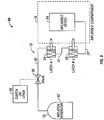
- emergency flotation system 90 includes a pressurized fluid source, such as an inflation reservoir 92 that stores a pressurized gas, such as air or nitrogen, for selectively inflating an inflatable device 94, such as a life raft.
- a pressure line 30 fluidly links inflation reservoir 92 with latching assembly 19 through a valve 96.
- Valve 96 is normally closed so that fluid communication between inflation reservoir 92 and latching assembly 19 is prevented.
- the system may be activated by an electronic switch in the cockpit or a manual lever 98.
- switch or lever 98 allows pressurized fluid to be injected into latching assembly 19, which activates one or more latches 28, and into inflatable device 94.
- latches 28 may be connected either in series (shown in FIG. 9 ) or parallel (shown in FIG. 10 ) with inflation reservoir 92 as desired.
- a series connection between latches 28 provides sequential unlatching of the plurality of latches which is followed by inflation of inflatable device 94.
- a series connection maybe used to reduce the length of pressure line required for the system.
- a parallel connection between latches 28 and inflation reservoir 92 allows the plurality of latches to be unlatched simultaneously with the inflation of inflatable device 94 thereafter.
- an inlet of each latch 28 is directly coupled to inflation reservoir 92 through pressure line 30 and an outlet of each latch is directly coupled to inflatable device 94.
- a pressure line 31 between an outlet of the first latch 28 and an inlet of the second latch 28 would not be required.
Claims (19)
- Druckaktivierte Verriegelung zum Verriegeln einer Nottür eines Flugzeug-Notflotationssystems, welche Folgendes aufweist:ein Verriegelungsgehäuse (46) mit einem Fluideinlass (34) und einem Fluidauslass (36), der in Längsrichtung vom Fluideinlass (34) beabstandet ist,einen Verriegelungsstift (40) mit einem Zwischenabschnitt (54), der sich aus dem Verriegelungsgehäuse (46) in einer verriegelten Position heraus erstreckt, und einem Dichtungsabschnitt (51), wobei der Verriegelungsstift (40) dafür ausgelegt ist, innerhalb des Verriegelungsgehäuses (46) zwischen der verriegelten Position und einer nicht verriegelten Position, in der der Zwischenabschnitt (54) in das Verriegelungsgehäuse (46) zurückgezogen ist, zu gleiten, undein inneres Vorspannungselement (56), das innerhalb des Verriegelungsgehäuses (46) angeordnet ist und dafür ausgelegt ist, den Verriegelungsstift (40) in die verriegelte Position vorzuspannen,wobei der Zwischenabschnitt (54) des Verriegelungsstifts (40) dafür eingerichtet ist, mit einem Verriegelungsansatz (38) einer Nottür (20) in Eingriff gebracht zu werden, und der Dichtungsabschnitt des Verriegelungsstifts dafür ausgelegt ist, eine Fluidkommunikation zwischen dem Fluideinlass und dem Fluidauslass zu verhindern, wenn sich die Verriegelung in der verriegelten Position befindet, undwobei der Zwischenabschnitt (54) des Verriegelungsstifts (40) dafür eingerichtet ist, vom Verriegelungsansatz (38) der Nottür (20) getrennt zu werden, und der Dichtungsabschnitt (51) des Verriegelungsstifts (40) dafür ausgelegt ist, eine Fluidkommunikation zwischen dem Fluideinlass (34) und dem Fluidauslass (36) zu ermöglichen, wenn sich der Verriegelungsstift (40) in der nicht verriegelten Position befindet.
- Druckaktivierte Verriegelung nach Anspruch 1, wobei das innere Vorspannungselement eine Feder (56) ist.
- Druckaktivierte Verriegelung nach Anspruch 1, wobei der Verriegelungsansatz (38) im Wesentlichen an das Verriegelungsgehäuse (46) angrenzt, wenn sich der Verriegelungsstift (40) in der verriegelten Position befindet.
- Druckaktivierte Verriegelung nach Anspruch 3, wobei der Zwischenabschnitt (54) dafür ausgelegt ist, vom Verriegelungsansatz (38) getrennt zu sein, wenn sich der Verriegelungsstift (40) zwischen der verriegelten Position und der nicht verriegelten Position befindet.
- Druckaktivierte Verriegelung nach Anspruch 1, wobei das Verriegelungsgehäuse (46) eine Längsbohrung (44) aufweist und sich ein Teil des Verriegelungsstifts (40) in der Längsbohrung befindet.
- Druckaktivierte Verriegelung nach Anspruch 5, wobei der Fluideinlass (34) im Wesentlichen angrenzend an ein erstes Ende der Längsbohrung in Fluidkommunikation mit der Längsbohrung (44) steht und der Fluidauslass (36) im Wesentlichen angrenzend an ein zweites Ende der Längsbohrung (44) in Fluidkommunikation mit der Längsbohrung steht.
- Druckaktivierte Verriegelung nach Anspruch 1, welche ferner zumindest ein Dichtungselement (50) aufweist, das dafür ausgelegt ist, eine Fluiddichtung zwischen dem Verriegelungsstift (40) und dem Verriegelungsgehäuse (46) zu erzeugen.
- Druckaktivierte Verriegelung nach Anspruch 7, wobei das Dichtungselement ein O-Ring ist.
- Druckaktivierte Verriegelung nach Anspruch 1, wobei
das Verriegelungsgehäuse (46) einen Fluideinlass (34) und einen in Längsrichtung vom Fluideinlass (34) beabstandeten Fluidauslass (36) aufweist und
das innere Vorspannungselement (56) innerhalb des Verriegelungsgehäuses (46) angeordnet ist. - Druckaktivierte Verriegelung nach Anspruch 9, wobei das innere Vorspannungselement eine Schraubenfeder (56) ist.
- Druckaktivierte Verriegelung nach Anspruch 9, wobei das innere Vorspannungselement aus mehreren Belville-Federunterlegscheiben besteht.
- Druckaktivierte Verriegelung nach Anspruch 9, wobei der Verriegelungsstift (40) dafür ausgelegt ist, vom Verriegelungsansatz (38) fort zu gleiten, wenn er aus der verriegelten Position in die nicht verriegelte Position bewegt wird.
- Druckaktivierte Verriegelung nach Anspruch 12, wobei sich der Fluidauslass (36) weiter proximal vom Verriegelungsansatz (38) befindet als der Fluideinlass (34).
- Druckaktivierte Verriegelung nach Anspruch 9, wobei der Verriegelungsstift (40) einen Bewegungsbegrenzungsanschlag (70, 71) aufweist, der dafür ausgelegt ist, die Bewegung des Verriegelungsstifts (40) zu begrenzen, so dass der Dichtungsabschnitt (51) vom Fluideinlass (34) beabstandet ist, wenn sich der Verriegelungsstift (40) in der verriegelten Position befindet.
- Notflotationssystem, welches Folgendes aufweist:eine Druckfluidquelle (92),ein Aufnahmefach (18) für eine aufblasbare Vorrichtung mit einem Deckel und Deckelverriegelungsansätzen,mehrere druckaktivierte Verriegelungen (28) nach einem der Ansprüche 1 bis 14, die dafür ausgelegt sind, selektiv in die Deckelverriegelungsansätze einzugreifen, undeine aufblasbare Vorrichtung (94), die durch die mehreren druckaktivierten Verriegelungen in Fluidkommunikation mit der Druckfluidquelle (92) gekoppelt ist.
- Notflotationssystem nach Anspruch 15, wobei die mehreren druckaktivierten Verriegelungen in Reihe in Fluidkopplung miteinander stehen.
- Notflotationssystem nach Anspruch 15, wobei die mehreren druckaktivierten Verriegelungen parallel in Fluidkopplung miteinander stehen.
- Notflotationssystem nach Anspruch 15, welches ferner ein Druckventil (96) aufweist, das zwischen der Druckfluidquelle (92) und den mehreren druckaktivierten Verriegelungen angeordnet ist.
- Notflotationssystem nach Anspruch 18, wobei das Druckventil dafür eingerichtet ist, fern betrieben zu werden.
Applications Claiming Priority (2)
| Application Number | Priority Date | Filing Date | Title |
|---|---|---|---|
| US11/361,821 US7329164B2 (en) | 2006-02-24 | 2006-02-24 | Pressure activated latch |
| PCT/US2007/004595 WO2007100603A2 (en) | 2006-02-24 | 2007-02-22 | Pressure activated latch |
Publications (3)
| Publication Number | Publication Date |
|---|---|
| EP1989101A2 EP1989101A2 (de) | 2008-11-12 |
| EP1989101A4 EP1989101A4 (de) | 2013-08-21 |
| EP1989101B1 true EP1989101B1 (de) | 2018-01-10 |
Family
ID=38444600
Family Applications (1)
| Application Number | Title | Priority Date | Filing Date |
|---|---|---|---|
| EP07751364.6A Active EP1989101B1 (de) | 2006-02-24 | 2007-02-22 | Druckaktivierte verriegelung |
Country Status (4)
| Country | Link |
|---|---|
| US (1) | US7329164B2 (de) |
| EP (1) | EP1989101B1 (de) |
| CA (1) | CA2643317C (de) |
| WO (1) | WO2007100603A2 (de) |
Families Citing this family (13)
| Publication number | Priority date | Publication date | Assignee | Title |
|---|---|---|---|---|
| US7658417B2 (en) * | 2006-02-24 | 2010-02-09 | Apical Industries, Inc. | Hose hinge assembly |
| WO2008028223A1 (en) * | 2006-09-04 | 2008-03-13 | Michael John Watmough | Pneumaticaily operated barrier lock |
| DE102006056442B4 (de) * | 2006-11-28 | 2010-10-28 | Eurocopter Deutschland Gmbh | Türschloss für Türen von Luftfahrzeugen, insbesondere von Hubschraubern |
| DE102009058437B4 (de) * | 2009-12-16 | 2011-11-10 | Airbus Operations Gmbh | Aufbewahrungssystem für eine Notausrüstungseinrichtung |
| US9238508B2 (en) * | 2011-02-02 | 2016-01-19 | Textron Innovations Inc. | Window mounted raft system |
| US8961062B2 (en) * | 2012-06-28 | 2015-02-24 | Ford Global Technologies, Llc | Inertial lockout mechanism |
| CN104196839B (zh) * | 2014-08-13 | 2016-05-04 | 北京宇航系统工程研究所 | 一种新型自动关闭口盖锁 |
| US9630699B2 (en) * | 2015-02-12 | 2017-04-25 | Northrop Grumman Systems Corporation | Magnetic latching system with inflatable seal |
| US10112695B2 (en) * | 2015-08-20 | 2018-10-30 | Georgian Aerospace Llc | Receptacle, payload assembly and related methods for an aircraft |
| US9689412B1 (en) * | 2017-02-01 | 2017-06-27 | Northrop Grumman Systems Corporation | Method and apparatus for magnetic panel attachment |
| EP3653825B1 (de) * | 2018-11-13 | 2021-08-25 | Ratier-Figeac SAS | Gasversorgungsanordnung für flugzeugtüraktuator und evakuierungssystem |
| CN111457796A (zh) * | 2020-04-13 | 2020-07-28 | 北京中科宇航技术有限公司 | 航天用自动关闭口盖的锁扣、口盖及运载火箭 |
| US11926433B2 (en) * | 2021-07-30 | 2024-03-12 | Airbus Americas, Inc. | Mechanical time delay security latches and methods |
Family Cites Families (17)
| Publication number | Priority date | Publication date | Assignee | Title |
|---|---|---|---|---|
| US1776865A (en) * | 1929-10-18 | 1930-09-30 | Glenn L Martin Co | Airplane flotation system |
| US2264321A (en) * | 1939-12-26 | 1941-12-02 | Frank G Manson | Lifesaving apparatus |
| US2475978A (en) * | 1946-08-07 | 1949-07-12 | Boeing Co | Aircraft release mechanism |
| US3144224A (en) * | 1962-09-28 | 1964-08-11 | Dee B Carroll | Escape hatches for passenger airliner |
| US3973744A (en) * | 1975-06-12 | 1976-08-10 | Sargent Industries, Inc. | Latching mechanism |
| US4104964A (en) * | 1977-04-05 | 1978-08-08 | The Boeing Company | Apparatus for packing aircraft escape devices |
| DE2800396C3 (de) * | 1978-01-05 | 1981-03-26 | Bergwerksverband Gmbh, 45307 Essen | Verriegelungsvorrichtung, insbesondere für Koksofentüren |
| US4519782A (en) * | 1980-02-19 | 1985-05-28 | The B. F. Goodrich Company | Escape slide and life raft |
| FR2576217B1 (fr) * | 1985-01-24 | 1987-03-06 | Aerospatiale | Mecanisme pour l'actionnement automatique d'un dispositif de sauvetage lors de l'ouverture d'une porte d'issue |
| US4866963A (en) * | 1988-02-22 | 1989-09-19 | Leininger David E | Security system for loading doors |
| US5360186A (en) * | 1993-07-26 | 1994-11-01 | The B. F. Goodrich Company | Inflatable slide raft assembly |
| US5515649A (en) * | 1994-08-15 | 1996-05-14 | Gentleman Door Company | Automatic door operator |
| US6068288A (en) * | 1998-03-26 | 2000-05-30 | Sturman/Tlx Llc | Dynamic control valve system adapted for inflatable restraint systems for vehicles |
| US6457675B1 (en) * | 2001-06-25 | 2002-10-01 | The Boeing Company | Hydraulic actuation system for cargo doors with cam-type latches |
| US6769647B2 (en) * | 2002-04-18 | 2004-08-03 | Goodrich Corporation | Automatic inflation system for evacuation slide |
| US7658417B2 (en) * | 2006-02-24 | 2010-02-09 | Apical Industries, Inc. | Hose hinge assembly |
| WO2007100601A2 (en) * | 2006-02-24 | 2007-09-07 | Apical Industries, Inc. | Door pod assembly |
-
2006
- 2006-02-24 US US11/361,821 patent/US7329164B2/en active Active
-
2007
- 2007-02-22 CA CA2643317A patent/CA2643317C/en active Active
- 2007-02-22 WO PCT/US2007/004595 patent/WO2007100603A2/en active Application Filing
- 2007-02-22 EP EP07751364.6A patent/EP1989101B1/de active Active
Non-Patent Citations (1)
| Title |
|---|
| None * |
Also Published As
| Publication number | Publication date |
|---|---|
| WO2007100603A9 (en) | 2007-12-21 |
| EP1989101A4 (de) | 2013-08-21 |
| CA2643317C (en) | 2019-06-25 |
| WO2007100603A3 (en) | 2008-11-13 |
| WO2007100603A2 (en) | 2007-09-07 |
| CA2643317A1 (en) | 2007-09-07 |
| US7329164B2 (en) | 2008-02-12 |
| EP1989101A2 (de) | 2008-11-12 |
| US20070202759A1 (en) | 2007-08-30 |
Similar Documents
| Publication | Publication Date | Title |
|---|---|---|
| EP1989101B1 (de) | Druckaktivierte verriegelung | |
| EP1989108B1 (de) | Türhalterbaugruppe | |
| US6457675B1 (en) | Hydraulic actuation system for cargo doors with cam-type latches | |
| US7380755B2 (en) | Frangible pneumatic latch | |
| EP0999976B1 (de) | Notausgangsvorrichtung | |
| US7445180B2 (en) | Actuation system for tail section of aircraft | |
| US7644739B1 (en) | Pressurized actuation system for inflatable structures | |
| US8100363B2 (en) | Hatch equipped with at least one locking socket capable of being actuated on each side of the hatch | |
| US11119516B2 (en) | Solenoid-operated pressure-regulator modules for inflation systems and methods thereof | |
| US4395000A (en) | Latch and lock mechanism for an aircraft cargo door assembly | |
| CA2643318C (en) | Actuator box assembly | |
| EP1989141B1 (de) | Schlauchscharnieranordnung | |
| US7434600B1 (en) | Pressurized actuator system for inflatable structures | |
| US6997414B2 (en) | Cargo door modification to ease emergency egress | |
| US9989166B2 (en) | Directly coupled valve actuator for inflatable structures | |
| RU2376206C1 (ru) | Система открытия аварийного выхода | |
| US4927098A (en) | Mechanism for fastening a life-saving device of the simple evacuation slide or dinghy type for aircraft | |
| US20230192302A1 (en) | Emergency device actuation assemblies and aircraft including same | |
| US20080272607A1 (en) | Dual release actuator assembly |
Legal Events
| Date | Code | Title | Description |
|---|---|---|---|
| PUAI | Public reference made under article 153(3) epc to a published international application that has entered the european phase |
Free format text: ORIGINAL CODE: 0009012 |
|
| 17P | Request for examination filed |
Effective date: 20080924 |
|
| AK | Designated contracting states |
Kind code of ref document: A2 Designated state(s): AT BE BG CH CY CZ DE DK EE ES FI FR GB GR HU IE IS IT LI LT LU LV MC NL PL PT RO SE SI SK TR |
|
| AX | Request for extension of the european patent |
Extension state: AL BA HR MK RS |
|
| R17D | Deferred search report published (corrected) |
Effective date: 20081113 |
|
| DAX | Request for extension of the european patent (deleted) | ||
| A4 | Supplementary search report drawn up and despatched |
Effective date: 20130722 |
|
| RIC1 | Information provided on ipc code assigned before grant |
Ipc: E05B 51/02 20060101ALI20130716BHEP Ipc: B63B 35/58 20060101AFI20130716BHEP Ipc: B64C 1/14 20060101ALI20130716BHEP Ipc: E05B 47/00 20060101ALI20130716BHEP |
|
| GRAP | Despatch of communication of intention to grant a patent |
Free format text: ORIGINAL CODE: EPIDOSNIGR1 |
|
| RIC1 | Information provided on ipc code assigned before grant |
Ipc: E05B 51/02 20060101ALI20170614BHEP Ipc: B64C 1/14 20060101ALI20170614BHEP Ipc: E05B 47/00 20060101ALI20170614BHEP Ipc: B63B 35/58 20060101AFI20170614BHEP |
|
| INTG | Intention to grant announced |
Effective date: 20170720 |
|
| GRAS | Grant fee paid |
Free format text: ORIGINAL CODE: EPIDOSNIGR3 |
|
| GRAA | (expected) grant |
Free format text: ORIGINAL CODE: 0009210 |
|
| RAP1 | Party data changed (applicant data changed or rights of an application transferred) |
Owner name: APICAL INDUSTRIES, INC. |
|
| AK | Designated contracting states |
Kind code of ref document: B1 Designated state(s): AT BE BG CH CY CZ DE DK EE ES FI FR GB GR HU IE IS IT LI LT LU LV MC NL PL PT RO SE SI SK TR |
|
| REG | Reference to a national code |
Ref country code: GB Ref legal event code: FG4D |
|
| REG | Reference to a national code |
Ref country code: CH Ref legal event code: EP Ref country code: AT Ref legal event code: REF Ref document number: 962082 Country of ref document: AT Kind code of ref document: T Effective date: 20180115 |
|
| REG | Reference to a national code |
Ref country code: IE Ref legal event code: FG4D |
|
| REG | Reference to a national code |
Ref country code: DE Ref legal event code: R096 Ref document number: 602007053658 Country of ref document: DE |
|
| REG | Reference to a national code |
Ref country code: FR Ref legal event code: PLFP Year of fee payment: 12 |
|
| REG | Reference to a national code |
Ref country code: NL Ref legal event code: MP Effective date: 20180110 |
|
| REG | Reference to a national code |
Ref country code: AT Ref legal event code: MK05 Ref document number: 962082 Country of ref document: AT Kind code of ref document: T Effective date: 20180110 |
|
| PG25 | Lapsed in a contracting state [announced via postgrant information from national office to epo] |
Ref country code: NL Free format text: LAPSE BECAUSE OF FAILURE TO SUBMIT A TRANSLATION OF THE DESCRIPTION OR TO PAY THE FEE WITHIN THE PRESCRIBED TIME-LIMIT Effective date: 20180110 |
|
| PG25 | Lapsed in a contracting state [announced via postgrant information from national office to epo] |
Ref country code: FI Free format text: LAPSE BECAUSE OF FAILURE TO SUBMIT A TRANSLATION OF THE DESCRIPTION OR TO PAY THE FEE WITHIN THE PRESCRIBED TIME-LIMIT Effective date: 20180110 Ref country code: ES Free format text: LAPSE BECAUSE OF FAILURE TO SUBMIT A TRANSLATION OF THE DESCRIPTION OR TO PAY THE FEE WITHIN THE PRESCRIBED TIME-LIMIT Effective date: 20180110 Ref country code: CY Free format text: LAPSE BECAUSE OF FAILURE TO SUBMIT A TRANSLATION OF THE DESCRIPTION OR TO PAY THE FEE WITHIN THE PRESCRIBED TIME-LIMIT Effective date: 20180110 Ref country code: LT Free format text: LAPSE BECAUSE OF FAILURE TO SUBMIT A TRANSLATION OF THE DESCRIPTION OR TO PAY THE FEE WITHIN THE PRESCRIBED TIME-LIMIT Effective date: 20180110 |
|
| PG25 | Lapsed in a contracting state [announced via postgrant information from national office to epo] |
Ref country code: LV Free format text: LAPSE BECAUSE OF FAILURE TO SUBMIT A TRANSLATION OF THE DESCRIPTION OR TO PAY THE FEE WITHIN THE PRESCRIBED TIME-LIMIT Effective date: 20180110 Ref country code: AT Free format text: LAPSE BECAUSE OF FAILURE TO SUBMIT A TRANSLATION OF THE DESCRIPTION OR TO PAY THE FEE WITHIN THE PRESCRIBED TIME-LIMIT Effective date: 20180110 Ref country code: IS Free format text: LAPSE BECAUSE OF FAILURE TO SUBMIT A TRANSLATION OF THE DESCRIPTION OR TO PAY THE FEE WITHIN THE PRESCRIBED TIME-LIMIT Effective date: 20180510 Ref country code: SE Free format text: LAPSE BECAUSE OF FAILURE TO SUBMIT A TRANSLATION OF THE DESCRIPTION OR TO PAY THE FEE WITHIN THE PRESCRIBED TIME-LIMIT Effective date: 20180110 Ref country code: BG Free format text: LAPSE BECAUSE OF FAILURE TO SUBMIT A TRANSLATION OF THE DESCRIPTION OR TO PAY THE FEE WITHIN THE PRESCRIBED TIME-LIMIT Effective date: 20180410 Ref country code: GR Free format text: LAPSE BECAUSE OF FAILURE TO SUBMIT A TRANSLATION OF THE DESCRIPTION OR TO PAY THE FEE WITHIN THE PRESCRIBED TIME-LIMIT Effective date: 20180411 Ref country code: PL Free format text: LAPSE BECAUSE OF FAILURE TO SUBMIT A TRANSLATION OF THE DESCRIPTION OR TO PAY THE FEE WITHIN THE PRESCRIBED TIME-LIMIT Effective date: 20180110 |
|
| REG | Reference to a national code |
Ref country code: CH Ref legal event code: PL |
|
| REG | Reference to a national code |
Ref country code: DE Ref legal event code: R097 Ref document number: 602007053658 Country of ref document: DE |
|
| PG25 | Lapsed in a contracting state [announced via postgrant information from national office to epo] |
Ref country code: RO Free format text: LAPSE BECAUSE OF FAILURE TO SUBMIT A TRANSLATION OF THE DESCRIPTION OR TO PAY THE FEE WITHIN THE PRESCRIBED TIME-LIMIT Effective date: 20180110 Ref country code: EE Free format text: LAPSE BECAUSE OF FAILURE TO SUBMIT A TRANSLATION OF THE DESCRIPTION OR TO PAY THE FEE WITHIN THE PRESCRIBED TIME-LIMIT Effective date: 20180110 Ref country code: MC Free format text: LAPSE BECAUSE OF FAILURE TO SUBMIT A TRANSLATION OF THE DESCRIPTION OR TO PAY THE FEE WITHIN THE PRESCRIBED TIME-LIMIT Effective date: 20180110 |
|
| PLBE | No opposition filed within time limit |
Free format text: ORIGINAL CODE: 0009261 |
|
| STAA | Information on the status of an ep patent application or granted ep patent |
Free format text: STATUS: NO OPPOSITION FILED WITHIN TIME LIMIT |
|
| REG | Reference to a national code |
Ref country code: IE Ref legal event code: MM4A |
|
| REG | Reference to a national code |
Ref country code: BE Ref legal event code: MM Effective date: 20180228 |
|
| PG25 | Lapsed in a contracting state [announced via postgrant information from national office to epo] |
Ref country code: CH Free format text: LAPSE BECAUSE OF NON-PAYMENT OF DUE FEES Effective date: 20180228 Ref country code: SK Free format text: LAPSE BECAUSE OF FAILURE TO SUBMIT A TRANSLATION OF THE DESCRIPTION OR TO PAY THE FEE WITHIN THE PRESCRIBED TIME-LIMIT Effective date: 20180110 Ref country code: LI Free format text: LAPSE BECAUSE OF NON-PAYMENT OF DUE FEES Effective date: 20180228 Ref country code: LU Free format text: LAPSE BECAUSE OF NON-PAYMENT OF DUE FEES Effective date: 20180222 Ref country code: CZ Free format text: LAPSE BECAUSE OF FAILURE TO SUBMIT A TRANSLATION OF THE DESCRIPTION OR TO PAY THE FEE WITHIN THE PRESCRIBED TIME-LIMIT Effective date: 20180110 Ref country code: DK Free format text: LAPSE BECAUSE OF FAILURE TO SUBMIT A TRANSLATION OF THE DESCRIPTION OR TO PAY THE FEE WITHIN THE PRESCRIBED TIME-LIMIT Effective date: 20180110 |
|
| 26N | No opposition filed |
Effective date: 20181011 |
|
| PG25 | Lapsed in a contracting state [announced via postgrant information from national office to epo] |
Ref country code: IE Free format text: LAPSE BECAUSE OF NON-PAYMENT OF DUE FEES Effective date: 20180222 |
|
| PG25 | Lapsed in a contracting state [announced via postgrant information from national office to epo] |
Ref country code: SI Free format text: LAPSE BECAUSE OF FAILURE TO SUBMIT A TRANSLATION OF THE DESCRIPTION OR TO PAY THE FEE WITHIN THE PRESCRIBED TIME-LIMIT Effective date: 20180110 Ref country code: BE Free format text: LAPSE BECAUSE OF NON-PAYMENT OF DUE FEES Effective date: 20180228 |
|
| PG25 | Lapsed in a contracting state [announced via postgrant information from national office to epo] |
Ref country code: TR Free format text: LAPSE BECAUSE OF FAILURE TO SUBMIT A TRANSLATION OF THE DESCRIPTION OR TO PAY THE FEE WITHIN THE PRESCRIBED TIME-LIMIT Effective date: 20180110 |
|
| PG25 | Lapsed in a contracting state [announced via postgrant information from national office to epo] |
Ref country code: HU Free format text: LAPSE BECAUSE OF FAILURE TO SUBMIT A TRANSLATION OF THE DESCRIPTION OR TO PAY THE FEE WITHIN THE PRESCRIBED TIME-LIMIT; INVALID AB INITIO Effective date: 20070222 Ref country code: PT Free format text: LAPSE BECAUSE OF FAILURE TO SUBMIT A TRANSLATION OF THE DESCRIPTION OR TO PAY THE FEE WITHIN THE PRESCRIBED TIME-LIMIT Effective date: 20180110 |
|
| PGFP | Annual fee paid to national office [announced via postgrant information from national office to epo] |
Ref country code: FR Payment date: 20230110 Year of fee payment: 17 |
|
| PGFP | Annual fee paid to national office [announced via postgrant information from national office to epo] |
Ref country code: IT Payment date: 20230110 Year of fee payment: 17 |
|
| PGFP | Annual fee paid to national office [announced via postgrant information from national office to epo] |
Ref country code: DE Payment date: 20231228 Year of fee payment: 18 Ref country code: GB Payment date: 20240108 Year of fee payment: 18 |