EP1989079B1 - Console - Google Patents
Console Download PDFInfo
- Publication number
- EP1989079B1 EP1989079B1 EP07701803.4A EP07701803A EP1989079B1 EP 1989079 B1 EP1989079 B1 EP 1989079B1 EP 07701803 A EP07701803 A EP 07701803A EP 1989079 B1 EP1989079 B1 EP 1989079B1
- Authority
- EP
- European Patent Office
- Prior art keywords
- receiving body
- console
- lifting mechanism
- panel
- accessory
- Prior art date
- Legal status (The legal status is an assumption and is not a legal conclusion. Google has not performed a legal analysis and makes no representation as to the accuracy of the status listed.)
- Ceased
Links
- 230000007246 mechanism Effects 0.000 claims description 29
- 235000013361 beverage Nutrition 0.000 claims description 18
- 238000001816 cooling Methods 0.000 claims description 14
- 238000010438 heat treatment Methods 0.000 claims description 9
- 238000000638 solvent extraction Methods 0.000 claims description 3
- 230000000694 effects Effects 0.000 description 4
- 230000004044 response Effects 0.000 description 4
- 238000004378 air conditioning Methods 0.000 description 3
- 230000004913 activation Effects 0.000 description 2
- 230000008859 change Effects 0.000 description 2
- 230000006870 function Effects 0.000 description 2
- 239000007788 liquid Substances 0.000 description 2
- 230000003213 activating effect Effects 0.000 description 1
- 238000001514 detection method Methods 0.000 description 1
- 230000003028 elevating effect Effects 0.000 description 1
- -1 for example Substances 0.000 description 1
- 238000002844 melting Methods 0.000 description 1
- 230000008018 melting Effects 0.000 description 1
- 238000004806 packaging method and process Methods 0.000 description 1
- 230000000737 periodic effect Effects 0.000 description 1
- 239000003507 refrigerant Substances 0.000 description 1
- 238000005057 refrigeration Methods 0.000 description 1
- 230000003068 static effect Effects 0.000 description 1
- 238000009423 ventilation Methods 0.000 description 1
- 238000010792 warming Methods 0.000 description 1
- XLYOFNOQVPJJNP-UHFFFAOYSA-N water Substances O XLYOFNOQVPJJNP-UHFFFAOYSA-N 0.000 description 1
Images




Classifications
-
- B—PERFORMING OPERATIONS; TRANSPORTING
- B60—VEHICLES IN GENERAL
- B60R—VEHICLES, VEHICLE FITTINGS, OR VEHICLE PARTS, NOT OTHERWISE PROVIDED FOR
- B60R7/00—Stowing or holding appliances inside vehicle primarily intended for personal property smaller than suit-cases, e.g. travelling articles, or maps
- B60R7/04—Stowing or holding appliances inside vehicle primarily intended for personal property smaller than suit-cases, e.g. travelling articles, or maps in driver or passenger space, e.g. using racks
-
- B—PERFORMING OPERATIONS; TRANSPORTING
- B60—VEHICLES IN GENERAL
- B60N—SEATS SPECIALLY ADAPTED FOR VEHICLES; VEHICLE PASSENGER ACCOMMODATION NOT OTHERWISE PROVIDED FOR
- B60N2/00—Seats specially adapted for vehicles; Arrangement or mounting of seats in vehicles
- B60N2/75—Arm-rests
- B60N2/79—Adaptations for additional use of the arm-rests
- B60N2/793—Adaptations for additional use of the arm-rests for use as storage compartments
-
- B—PERFORMING OPERATIONS; TRANSPORTING
- B60—VEHICLES IN GENERAL
- B60N—SEATS SPECIALLY ADAPTED FOR VEHICLES; VEHICLE PASSENGER ACCOMMODATION NOT OTHERWISE PROVIDED FOR
- B60N3/00—Arrangements or adaptations of other passenger fittings, not otherwise provided for
- B60N3/10—Arrangements or adaptations of other passenger fittings, not otherwise provided for of receptacles for food or beverages, e.g. refrigerated
- B60N3/102—Arrangements or adaptations of other passenger fittings, not otherwise provided for of receptacles for food or beverages, e.g. refrigerated storable or foldable in a non-use position
-
- B—PERFORMING OPERATIONS; TRANSPORTING
- B60—VEHICLES IN GENERAL
- B60N—SEATS SPECIALLY ADAPTED FOR VEHICLES; VEHICLE PASSENGER ACCOMMODATION NOT OTHERWISE PROVIDED FOR
- B60N3/00—Arrangements or adaptations of other passenger fittings, not otherwise provided for
- B60N3/10—Arrangements or adaptations of other passenger fittings, not otherwise provided for of receptacles for food or beverages, e.g. refrigerated
- B60N3/104—Arrangements or adaptations of other passenger fittings, not otherwise provided for of receptacles for food or beverages, e.g. refrigerated with refrigerating or warming systems
Definitions
- the present invention generally relates to the field of automotive interiors, and more particularly to an automotive console having an accessory receiving body.
- accessory receiving bodies such as, storage compartments and the like.
- conventional accessory receiving bodies are usually limited in accessibility and not relatively ergonomic for the needs of all types of users, and/or more than one user, relative the location of many potential users proximate the accessory receiving body. Therefore, a need exists for improved accessory receiving bodies that are ergonomic and increase user accessibility, storage capacity, or the like.
- JP 05 338498 A discloses a console box provided in the interior of an automobile, which can change an upper capacity by moving up and down a variable member.
- US 6 279 977 B1 describes a computer dock within the armrest of an automobile between the driver and passenger seat, wherein the armrest includes an enclosure having a forward opening, a rearward opening and a passage therethrough. Therefore, a computer can be visible to the passengers in the front seats as well as to the passengers in the back seats.
- JP 2003 165388 A discloses a console box body formed of two divided box bodies, an upper and a lower.
- JP 07 009915 A shows a storage device for an automobile comprising a compartment box movable vertically in response to an opening/closing of an access panel.
- JP 09 202168 A describes a storage device for an automobile comprising a storage chamber and a food warming/refrigerating cabinet.
- Document JP-04-208655 A which can be considered as the starting point of the present invention shows a console for a vehicle, wherein an actuator formed by a switch causes a motor to drive a lifting mechanism to cause movement of the vehicle accessory from a first position to at least a second position.
- the switch is operably connected to the closure panel, see paragraph [0015].
- the actuator is a contact sensor so that engagement between the closure panel with the actuator instructs the vehicle accessory to move from the first to the said second position.
- An object of the present invention is to overcome the problems delineated hereinabove.
- a console for a vehicle comprising a closure panel and an actuator operably connected to the closure panel, whereupon engagement between the closure panel with the actuator instructs a vehicle accessory to move from a first position to at least one second position.
- the console further comprises a motor connected to the actuator, and a lifting mechanism connected to the motor and the vehicle accessory, wherein movement of the lifting mechanism is responsive to the actuation of the motor, wherein the actuator is a contact sensor that causes the motor to drive the lifting mechanism to cause movement of the vehicle accessory from the first position to the at least one second position.
- the lifting mechanism is defined by a scissor bridge and a ball screw.
- the lifting mechanism is defined by a ball screw, a bearing, and a stability post.
- the console further comprises a body defined by a floor and sidewalls extending axially from said floor, wherein said sidewalls are fixed relative to said floor, wherein the vehicle accessory defines a receiving body that is movably-disposed in the body for movement between said first and second positions and any position therebetween within the body, said receiving body accessible independent of said position thereof within the body.
- the receiving body further comprises a sidewall defining a depth (D); and one or more partitioning elements defining two or more stowage segments.
- the vehicle accessory further comprises a heating/cooling device and one or more beverage container receiving portions in thermal communication with the heating/cooling device.
- a console is shown generally at 10 in Figures 1 and 2 according to an embodiment of the invention.
- the illustrated console 10 includes accessory receiving bodies 100, 200, 300 that are generally located proximate one or more base portion(s) 14a-14c that are positioned over or secured to a body 16, such as, for example, a floor pan/panel of an automobile. Accordingly, the console 10 may be, if desired, a center floor console of an automotive interior.
- the accessory receiving bodies 100, 200, and 300 may each include a closure panel or the like and a detector operably associated therewith.
- the detector is a contact sensor such as an electronic contact sensor arranged in a predetermined position, such that a portion of closure panel operably contacts the detector to deploy an accessory, such as a beverage container or the like.
- an accessory such as a beverage container or the like.
- the accessory receiving body 100 which is generally shown in Figures 3-5 , includes a bottom panel 102.
- the bottom panel 102 may be presented in the form of a tray or the like.
- the bottom panel 102 may be elevated or otherwise adjusted between a stowed position and a presentment position; further, in an exemplary embodiment, the bottom panel 102 may be positioned at any position between the stowed position and the presentation position.
- bottom panel 102 may be configured for stowing items in a housing 104 without impairing a user's reach to the item(s).
- the accessory receiving body 200 which is shown generally in Figures 6-9B , includes a first access panel 202 and a second access panel 204.
- first access panel 202 will be referred to as a top access panel 202
- second access panel 204 will be referred to as a side access panel 204.
- the top access panel 202 and the side access panel 204 are adapted to allow access to the accessory receiving body 200 by one or more users from more than one access location.
- the accessory receiving body 300 which is shown generally in Figures 10-14 , is a vertically driven, adjustable beverage receptacle 300.
- the adjustable beverage receptacle 300 is adjustable between a first position and a second position and may be adjusted or configured to reside at any position therebetween.
- a base portion 302 may be presented at any of the foregoing positions such that the beverage receptacle 302 may be accessed and used at any each of these positions.
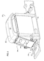
- the accessory receiving body 100 includes a bottom panel 102, a housing 104, a closure panel 106 ( Figure 3 ), and a panel lift mechanism 108.
- the bottom panel 102 provides a means to elevate content that may reside within housing 104, on top of bottom panel 102.
- the bottom panel 102 is adapted to move from a first, stowed position to a second, presentment position, without elevating or otherwise moving the housing 104 such that the overall elevation of accessory receiving body 100 and closure panel 106 remain static, while elevation of the bottom panel 102 and any contents thereon is dynamic.
- the closure panel 106 may be provided, for example, as a pair of "Bombay-style" doors and the lifting mechanism 108 may include, for example, a scissor-style bridge 116 and a ball screw 112 extending from a motor 110. While an electric motor 110 is shown, upon considering the present disclosure, it will be appreciated that the elevation of the bottom panel 102 may be adjusted using any prime mover, such as for example, a hydraulic mechanism, a pneumatic mechanism, or the like. Thus, the term "motor” should include all such prime moving mechanisms.
- closure panel 106 may be a single closure panel and thereby deviate from the aforementioned "Bombay-style" door, which will be appreciated by one of ordinary skill in the art after consulting the present disclosure such that the invention hereof should not be limited thereby.
- an electrical contact 118 or the like may be provided such that the detector 118 detects the presence of the closure panel 106 in an open position (e.g., in a predetermined position, a portion of the closure panel 106 may contact the electrical contact 118) and operably elevates bottom panel 102. While an electrical contact is described, it is understood that other contact sensing means are also suitable. Among other examples, a photodiode or the like may be provided.
- the detector 118 may also provide means lower the bottom panel to a stowed position when the of closure panel 106 moves away from the contact 118 or away from the predetermined position.
- an actuator 18 may be provided to actuate a stowing the bottom panel 102.
- the bottom panel 102 may be provided at any desirable depth, D.
- the depth, D, of the bottom panel 102 may vary in view of the height of a side-wall 103.
- the side-wall 103 and depth, D may be approximately the same about the perimeter of the bottom panel 102.
- the bottom panel 102 may include a plurality of stowage segments 105 defined by partitioning elements 107 for stowing a plurality of items, such as, for example, compact disc cases, CD, writing utensils, U, papers, coins, crayons, and the like. It will be appreciated that the depth, D, prevents contents located in/on the bottom panel 102 from spilling out of the housing 104 as the tray 102 rises from a stowed position to a presentment position.
- the motor 110 may cause rotation of a ball screw 112 to effect movement of the scissor-style bridge 116 to/from a stowed/presentment position.
- actuation of the motor 110 may automatically occur in response to a signal provided by a sensor 114 located proximate the bottom panel 102 for detecting the presence/weight of an item, such as a purse, P; as such, the sensor 114 may include, or, communicate with a controller (not shown) to signal activation of the motor 110.
- the lifting mechanism 108 may be initially in a presentment position ( Figure 3-4C ), and, when the sensor 114 detects the presence/weight of an item, the tray 102 may be moved automatically to a stowed position ( Figure 5 ). If desired, in an alternative embodiment, the motor 110 may be eliminated and the lifting mechanism 108 may include a mechanically controlled device that elevates and lower the bottom panel based on a condition.
- the condition may be the position or movement of the closure panel(s) or the like which could effect an elevation or lowering of the bottom panel via a linking mechanism (not shown.)
- the bottom panel 102 and/or lifting mechanism 108 may include a latch/lock (not shown) that retains the bottom panel 102 and lifting mechanism 108 in a stowed, deployed, or intermediate position (i.e. a partially stowed/deployed position).
- the closure panel 106 may be manually opened/closed by a force applied from movement of a user's hand. According to the invention , movement of the closure panel 106 trips a detector 118 in the form of a contact sensor, electrically connected or otherwise ( Figure 3 ), to cause the motor 110 to move the lifting mechanism 108 and bottom panel 102.
- the detector 118 may determine when the housing door 106 is moved to a fully opened position to initiate movement of the lifting mechanism 108 and tray bottom panel 102 by the motor 110; as such, if a relatively large item, such as, for example, a large purse, P, is positioned on the tray 102, the fully-opened positioning of the housing door 106 would not interfere with the upward movement of the purse, P, as the bottom panel 102 and purse, P, are moved from a stowed to a deployed position.
- a relatively large item such as, for example, a large purse, P
- movement of the closure panel 106 may be independent of the movement of the bottom panel 102 and lifting mechanism 108 (i.e. the closure panel 106 is not mechanically or electrically coupled to the lifting mechanism 108).
- a "disable mode" may be set, for example, by pressing a button 18 so that the bottom panel 102 is not responsive to manual or automatic movement of the housing door 106.
- movement of the closure panel 106 may be provided by a gear assembly, having, for example toothed, arcuate portions 120 extending from the closure panel that respectively mesh with cooperating toothed disks 122. Accordingly, if manual movement to one of the closure panels 106 is conducted by a user's hand, the toothed arcuate portions 120 and disks 122 causes a similar movement to the other one of the housing door 106. Conversely, the motor 110 may drive one of the disks 122 to effect movement of the closure panel 106 relative the movement of the toothed, arcuate portions 120 relative the disks 122.
- the accessory receiving body 200 includes a first, top access panel 202 and a second, side access panel 204. According to an exemplary arrangement, the accessory receiving body 200 may reside between a pair of vehicle seats (not shown), such as, for example, front/forward seats. A rear/rearward row of seats (not shown) may face the side access panel 204.
- the first, top access panel 202 may permit users, F, located in front/forward seats to access items, B, in the accessory receiving body 200 through a first opening 214 when the top access panel 202 is in the open position
- the second, side access panel 204 may permit users, R, located in the rear/rearward seats to access the items, B, through a second opening 216 in the accessory receiving body 200.
- access to the items, B, through the second opening 216 prevents the disturbance of front/forward seating occupants, F, that may utilize a cushioned top surface 206 of the top access panel 202 as an armrest when the top access panel 202 is in a closed position ( Figure 9B ).
- the top access panel 202 is hingably attached to a rearward portion of accessory receiving body 200
- the side access panel 204 is hingably attached to a bottom portion of accessory receiving body 200.
- the top access panel 202 and side access panel may be hingably attached in any known way and the invention should not be limited to the exemplary attachment.
- the accessory receiving body 200 may function as a refrigerator for maintaining items, such as, for example, beverage containers, B.
- an air duct 208 may provide a passage for cold air, A, from an air conditioning system to the accessory receiving body 200.
- an interior of the accessory receiving body 200 may include a cooling element 210, such as, for example, a refrigerator (which may include, e.g., a compressor, heat-exchange pipes, expansion valve, and refrigerant), re-freezable cold packs that are insertable into a sleeve within the accessory receiving body 200 or the like.
- a refrigerator which may include, e.g., a compressor, heat-exchange pipes, expansion valve, and refrigerant
- re-freezable cold packs that are insertable into a sleeve within the accessory receiving body 200 or the like.
- a tray 211 or the like may be placed over a bottom wall 213 of the accessory receiving body 200 for retaining ice cubes.
- element 208 which was previously described as an air duct, may be a drain for the purpose of permitting the evacuation of liquid, such as, for example, water from melting ice cubes, spilled beverage liquid from the beverage containers, B, or the like.
- the accessory receiving body 200 may include a temperature sensor 212 that communicates with a controller (not shown) for activating the cooling system, such as, for example, a cooling element 210 or air conditioning system for drawing cool air, A, into the accessory receiving body 200 upon detecting that the temperature condition of the accessory receiving body 200 has risen to a temperature condition higher than a programmed temperature condition.
- actuation of the cooling system 210 may be responsive to a periodic detection of the temperature of a cavity defined by the interior walls of the accessory receiving body 200, by, for example, the temperature sensor 212 according to a timer/counter that communicates with a controller.
- the opening and closing of one of or both the access panels 202, 204 may cause the activation of the cooling system 210 by providing a detector (not shown) in a predetermined position as previously described.
- the cooling system 210 may be deactivated if the temperature of the accessory receiving body 200 is maintained at a programmed temperature condition.
- the accessory receiving body 200 may function as a storage compartment for user items, including but not limited to, CD's, DVD's or the like (See Figure 7B , 8B ). While two uses for accessory receiving body 200 are herein described, upon considering the present disclosure, accessory receiving body 200 may be adapted to receive a variety of accessories.
- the top and/or side access panel 202, 204 may include a control system 215 that are operable by, for example, the occupants, F, R, respectively.
- the control system 215 may include, for example, heating/ventilation/air-conditioning (HVAC) controls, entertainment controls (e.g., radio, television, video games), or refrigeration controls for adjusting the temperature of the accessory receiving body 200.
- HVAC heating/ventilation/air-conditioning
- entertainment controls e.g., radio, television, video games
- refrigeration controls for adjusting the temperature of the accessory receiving body 200.
- the control system 215 may transmit instructions or data associated with an electronic control to one or more controllers.
- a secondary storage compartment 218 may be located, for example, proximate the side access panel 204.
- the secondary storage compartment 218 may be a beverage cradle slidably disposed within a bottom portion of the accessory receiving body 200.
- the accessory receiving body 300 is a beverage receptacle including a base 302 that defines one or more beverage receiving portions 304, and a lifting mechanism 310.
- a door/lid 306 may optionally be provided 312 to store or otherwise close out the base 302 and the beverage receiving portion 304 such that the accessory receiving body 300 may be fully stowed within the console 100.
- the beverage receiving portion 304 is adjustable between a first, fully retracted position and a second, fully extended position, and may be infinitely adjusted to every position therebetween for presentment and use. As such, the beverage receiving portion 304 may be accessed and used at any of the foregoing positions, including the fully retracted position. For example, if the door 306 is provided, the door 306 may be opened to allow use of the beverage receptacle 300 in the fully retracted position.
- a motor 318 is provided to operably, vertically deploy or vertically adjust the position of base 302 to any of the foregoing positions.
- the lifting mechanism 310 can include the motor 318 operably connected to a ball screw 312 relative to a bearing 314. Actuation of the motor 310 causes rotation of a ball screw 312 relative to the bearing 314 to effect vertical movement of the base 302 to/from a stowed/presentment position.
- a post 316 may extend from the base portion 14c to provide additional stability to the base 302.
- the ball screw 312 and post 316 may enlist the packaging of the base 302. Specifically, the definition of two beverage receiving portions 322 creates a space therebetween which can be adapted to vertically mount one or both of the ball screw 312 and post 316 thereon.
- condition of the base 302 may be changed responsive to, for example, movement of the lid 306.
- movement of lid 306 from a closed state to an open state may change (or any actuator 18) the condition of the base 302 from the fully retracted position to the presentment position (which may be, e.g., the fully extended position).
- the condition of the base 302 may be changed in response to a detector 324 in the form of an electrical contact that detects the presence of the lid 306 in a predetermined position (e.g., in an open position, a portion of the closure panel may contact the detector 324) to operably present the base portion 302.
- a detector 324 in the form of an electrical contact that detects the presence of the lid 306 in a predetermined position (e.g., in an open position, a portion of the closure panel may contact the detector 324) to operably present the base portion 302.
- a predetermined position e.g., in an open position, a portion of the closure panel may contact the detector 324
- a photodiode or the like may be provided.
- the lid 306 is slidably disposed over the base portion 302 and may be opened/closed manually by a force applied by a user's hand proximate a lip 308 or the like.
- the opening/closing movement of the slidable lid 306 may trip a detector 324 to cause automatic movement of the lifting mechanism 310 by the motor 318.
- an end 326 of the slidable lid 306, may, for example, contact the detector 324 so as to provide clearance for movement of the base 302 from a fully retracted to a presentment position.
- movement of the lifting mechanism 310 may occur when the slidable lid 306 is moved from a closed position ( Figures 11 , 13 ) to a fully opened position ( Figures 12 , 14 ).
- the fully opened position of the slidable lid 306 maybe determined by the detector 324.
- the base portion 302 may be moved from the fully retracted position to a presentment position such that the base portion 302 may be presented to a user until/as the slidable lid 306 is opened.
- the accessory receiving body 300 may include a heating/cooling device 328 for heating/cooling a beverage container, B. While a heating/cooling device 328 is disclosed, the present invention should not be limited thereby.
- the heating/cooling device 328 may include, for example, a fan located in an air duct 330 of a vehicle's HVAC system.
- An embodiment of the accessory receiving body 300 may include a memory for programming an intermediate position of the tray 304 (i.e. a partially deployed position of the tray 304) relative a position of any one of a plurality of unique vehicle occupant settings that may or may not be associated with, for example, unique vehicle occupant settings related to vehicle seats, operator pedals, mirrors, radio station setting, or the like.
Landscapes
- Engineering & Computer Science (AREA)
- Mechanical Engineering (AREA)
- Physics & Mathematics (AREA)
- Thermal Sciences (AREA)
- Transportation (AREA)
- Aviation & Aerospace Engineering (AREA)
- Vehicle Step Arrangements And Article Storage (AREA)
Description
- The present invention generally relates to the field of automotive interiors, and more particularly to an automotive console having an accessory receiving body.
- It is known that automotive interiors include accessory receiving bodies, such as, storage compartments and the like. However, conventional accessory receiving bodies are usually limited in accessibility and not relatively ergonomic for the needs of all types of users, and/or more than one user, relative the location of many potential users proximate the accessory receiving body. Therefore, a need exists for improved accessory receiving bodies that are ergonomic and increase user accessibility, storage capacity, or the like.
-
JP 05 338498 A -
US 6 279 977 B1 describes a computer dock within the armrest of an automobile between the driver and passenger seat, wherein the armrest includes an enclosure having a forward opening, a rearward opening and a passage therethrough. Therefore, a computer can be visible to the passengers in the front seats as well as to the passengers in the back seats. -
JP 2003 165388 A -
JP 07 009915 A -
JP 09 202168 A - Document
JP-04-208655 A - An object of the present invention is to overcome the problems delineated hereinabove.
- In accordance with the invention there is provided, a console for a vehicle comprising a closure panel and an actuator operably connected to the closure panel, whereupon engagement between the closure panel with the actuator instructs a vehicle accessory to move from a first position to at least one second position.
- In accordance with a further embodiment of the invention, the console further comprises a motor connected to the actuator, and a lifting mechanism connected to the motor and the vehicle accessory, wherein movement of the lifting mechanism is responsive to the actuation of the motor, wherein the actuator is a contact sensor that causes the motor to drive the lifting mechanism to cause movement of the vehicle accessory from the first position to the at least one second position.
- In accordance with another aspect of the invention, the lifting mechanism is defined by a scissor bridge and a ball screw. In accordance with yet another aspect of the invention, the lifting mechanism is defined by a ball screw, a bearing, and a stability post.
- In accordance with another embodiment of the invention, the console further comprises a body defined by a floor and sidewalls extending axially from said floor, wherein said sidewalls are fixed relative to said floor, wherein the vehicle accessory defines a receiving body that is movably-disposed in the body for movement between said first and second positions and any position therebetween within the body, said receiving body accessible independent of said position thereof within the body.
- In accordance with another aspect of the invention, the receiving body further comprises a sidewall defining a depth (D); and one or more partitioning elements defining two or more stowage segments.
- In accordance with yet another aspect of the invention, the vehicle accessory further comprises a heating/cooling device and one or more beverage container receiving portions in thermal communication with the heating/cooling device.
- This and other objects of the invention can be more fully appreciated from the following detailed description of the preferred embodiments.
- Exemplary embodiments of the invention will now be described in conjunction with the following drawings wherein like numerals represent like elements, and wherein:
-
Figure 1 is a perspective view of a console according to an embodiment of the invention; -
Figure 2 is a partial perspective view of the console according toFigure 1 ; -
Figure 3 is a perspective view of an accessory receiving body of the console ofFigure 1 according to an embodiment of the invention; -
Figure 4A is a perspective view of the accessory receiving body ofFigure 3 according to an embodiment of the invention; -
Figure 4B is a perspective view of the accessory receiving body ofFigure 3 according to an embodiment of the invention; -
Figure 4C is a perspective view of the accessory receiving body ofFigure 3 according to an embodiment of the invention; -
Figure 5 is a perspective view of the accessory receiving body ofFigure 3 according to an embodiment of the invention; -
Figure 6 is a perspective view of an accessory receiving body of the console ofFigure 1 according to an embodiment of the invention; -
Figure 7A is a top perspective view of the accessory receiving body ofFigure 6 according to an embodiment of the invention; -
Figure 7B is a top perspective view of an accessory receiving body according to an embodiment of the invention; -
Figure 8A is a side perspective view of the accessory receiving body ofFigure 6 according to an embodiment of the invention; -
Figure 8B is a side perspective view of the accessory receiving body ofFigure 7B according to an embodiment of the invention; -
Figure 9A is a cross-section view of the accessory receiving body ofFigures 7 and8 according toline 9A-9A ofFigure 7A ; -
Figure 9B is another cross-section view of the accessory receiving body ofFigures 7 and8 according to an embodiment of the invention; -
Figure 10 is a perspective view of an accessory receiving body of the console ofFigure 1 according to an embodiment of the invention; -
Figure 11 is a perspective view of the accessory receiving body ofFigure 10 according to an embodiment of the invention; -
Figure 12 is another perspective view of the accessory receiving body ofFigure 10 according to an embodiment of the invention; -
Figure 13 is a cross-section view of the accessory receiving body ofFigure 11 according to line 13-13; and -
Figure 14 is a cross-section view of the accessory receiving body ofFigure 12 according to line 14-14. - A console is shown generally at 10 in
Figures 1 and2 according to an embodiment of the invention. The illustratedconsole 10 includesaccessory receiving bodies body 16, such as, for example, a floor pan/panel of an automobile. Accordingly, theconsole 10 may be, if desired, a center floor console of an automotive interior. - Throughout this disclosure, the
accessory receiving bodies - According to an embodiment, the
accessory receiving body 100, which is generally shown inFigures 3-5 , includes abottom panel 102. According to an embodiment, thebottom panel 102 may be presented in the form of a tray or the like. Thebottom panel 102 may be elevated or otherwise adjusted between a stowed position and a presentment position; further, in an exemplary embodiment, thebottom panel 102 may be positioned at any position between the stowed position and the presentation position. According to an embodiment,bottom panel 102 may be configured for stowing items in ahousing 104 without impairing a user's reach to the item(s). - The
accessory receiving body 200, which is shown generally inFigures 6-9B , includes afirst access panel 202 and asecond access panel 204. For convenience thefirst access panel 202 will be referred to as atop access panel 202 and thesecond access panel 204 will be referred to as aside access panel 204. However, it is appreciated that the access panels should not be limited to the disclosed embodiments, and the invention should not be limited thereby. Thetop access panel 202 and theside access panel 204 are adapted to allow access to theaccessory receiving body 200 by one or more users from more than one access location. - The
accessory receiving body 300, which is shown generally inFigures 10-14 , is a vertically driven,adjustable beverage receptacle 300. Theadjustable beverage receptacle 300 is adjustable between a first position and a second position and may be adjusted or configured to reside at any position therebetween. In other words, abase portion 302 may be presented at any of the foregoing positions such that thebeverage receptacle 302 may be accessed and used at any each of these positions. - Referring to
Figures 3-5 , theaccessory receiving body 100 includes abottom panel 102, ahousing 104, a closure panel 106 (Figure 3 ), and apanel lift mechanism 108. According to an embodiment, thebottom panel 102 provides a means to elevate content that may reside withinhousing 104, on top ofbottom panel 102. Thebottom panel 102 is adapted to move from a first, stowed position to a second, presentment position, without elevating or otherwise moving thehousing 104 such that the overall elevation ofaccessory receiving body 100 andclosure panel 106 remain static, while elevation of thebottom panel 102 and any contents thereon is dynamic. - As illustrated, the
closure panel 106 may be provided, for example, as a pair of "Bombay-style" doors and thelifting mechanism 108 may include, for example, a scissor-style bridge 116 and aball screw 112 extending from amotor 110. While anelectric motor 110 is shown, upon considering the present disclosure, it will be appreciated that the elevation of thebottom panel 102 may be adjusted using any prime mover, such as for example, a hydraulic mechanism, a pneumatic mechanism, or the like. Thus, the term "motor" should include all such prime moving mechanisms. Similarly, theclosure panel 106 may be a single closure panel and thereby deviate from the aforementioned "Bombay-style" door, which will be appreciated by one of ordinary skill in the art after consulting the present disclosure such that the invention hereof should not be limited thereby. - In an embodiment, an
electrical contact 118 or the like may be provided such that thedetector 118 detects the presence of theclosure panel 106 in an open position (e.g., in a predetermined position, a portion of theclosure panel 106 may contact the electrical contact 118) and operably elevatesbottom panel 102. While an electrical contact is described, it is understood that other contact sensing means are also suitable. Among other examples, a photodiode or the like may be provided. - The
detector 118 may also provide means lower the bottom panel to a stowed position when the ofclosure panel 106 moves away from thecontact 118 or away from the predetermined position. Alternatively, anactuator 18 may be provided to actuate a stowing thebottom panel 102. Thus, upon an opening of theclosure panel 106, thebottom panel 102 elevates to a presentment position and a purse or a like may be more easily placed thereon; and, upon a second condition, such as a closing of theclosure panel 106, or upon any instruction (electrically or mechanically) provided thereto, thebottom panel 102 lowers to a stowed position. - As seen in
Figures 4A-4C , thebottom panel 102 may be provided at any desirable depth, D. According to an embodiment, illustrated inFigure 4A , the depth, D, of thebottom panel 102 may vary in view of the height of a side-wall 103. InFigures 4B and4C , the side-wall 103 and depth, D, may be approximately the same about the perimeter of thebottom panel 102. As illustrated inFigures 4B and4C , thebottom panel 102 may include a plurality ofstowage segments 105 defined by partitioningelements 107 for stowing a plurality of items, such as, for example, compact disc cases, CD, writing utensils, U, papers, coins, crayons, and the like. It will be appreciated that the depth, D, prevents contents located in/on thebottom panel 102 from spilling out of thehousing 104 as thetray 102 rises from a stowed position to a presentment position. - According to an embodiment, the
motor 110 may cause rotation of aball screw 112 to effect movement of the scissor-style bridge 116 to/from a stowed/presentment position. According to an embodiment not covered by the present invention, actuation of themotor 110 may automatically occur in response to a signal provided by asensor 114 located proximate thebottom panel 102 for detecting the presence/weight of an item, such as a purse, P; as such, thesensor 114 may include, or, communicate with a controller (not shown) to signal activation of themotor 110. Thelifting mechanism 108 may be initially in a presentment position (Figure 3-4C ), and, when thesensor 114 detects the presence/weight of an item, thetray 102 may be moved automatically to a stowed position (Figure 5 ). If desired, in an alternative embodiment, themotor 110 may be eliminated and thelifting mechanism 108 may include a mechanically controlled device that elevates and lower the bottom panel based on a condition. For example, the condition may be the position or movement of the closure panel(s) or the like which could effect an elevation or lowering of the bottom panel via a linking mechanism (not shown.) If desired, thebottom panel 102 and/orlifting mechanism 108 may include a latch/lock (not shown) that retains thebottom panel 102 andlifting mechanism 108 in a stowed, deployed, or intermediate position (i.e. a partially stowed/deployed position). - According to an embodiment, the
closure panel 106 may be manually opened/closed by a force applied from movement of a user's hand. According to the invention , movement of theclosure panel 106 trips adetector 118 in the form of a contact sensor, electrically connected or otherwise (Figure 3 ), to cause themotor 110 to move thelifting mechanism 108 andbottom panel 102. If desired, thedetector 118 may determine when thehousing door 106 is moved to a fully opened position to initiate movement of thelifting mechanism 108 and traybottom panel 102 by themotor 110; as such, if a relatively large item, such as, for example, a large purse, P, is positioned on thetray 102, the fully-opened positioning of thehousing door 106 would not interfere with the upward movement of the purse, P, as thebottom panel 102 and purse, P, are moved from a stowed to a deployed position. - While the foregoing example describes a specific arrangement of a closure panel and a
bottom panel 102, it will be appreciated that the disclosure hereof further contemplates any deployment and stowage of any accessory receiving body in response to a position of theclosure panel 106 in relation to adetector 118. - According to an embodiment, movement of the
closure panel 106 may be independent of the movement of thebottom panel 102 and lifting mechanism 108 (i.e. theclosure panel 106 is not mechanically or electrically coupled to the lifting mechanism 108). If desired, a "disable mode" may be set, for example, by pressing abutton 18 so that thebottom panel 102 is not responsive to manual or automatic movement of thehousing door 106. - According to an embodiment, movement of the
closure panel 106 may be provided by a gear assembly, having, for example toothed,arcuate portions 120 extending from the closure panel that respectively mesh with cooperatingtoothed disks 122. Accordingly, if manual movement to one of theclosure panels 106 is conducted by a user's hand, the toothedarcuate portions 120 anddisks 122 causes a similar movement to the other one of thehousing door 106. Conversely, themotor 110 may drive one of thedisks 122 to effect movement of theclosure panel 106 relative the movement of the toothed,arcuate portions 120 relative thedisks 122. - Referring to
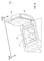
Figures 6-9B , theaccessory receiving body 200 includes a first,top access panel 202 and a second,side access panel 204. According to an exemplary arrangement, theaccessory receiving body 200 may reside between a pair of vehicle seats (not shown), such as, for example, front/forward seats. A rear/rearward row of seats (not shown) may face theside access panel 204. As such, referring toFigure 9A , the first,top access panel 202 may permit users, F, located in front/forward seats to access items, B, in theaccessory receiving body 200 through afirst opening 214 when thetop access panel 202 is in the open position, and, the second,side access panel 204 may permit users, R, located in the rear/rearward seats to access the items, B, through asecond opening 216 in theaccessory receiving body 200. Accordingly, access to the items, B, through thesecond opening 216 prevents the disturbance of front/forward seating occupants, F, that may utilize a cushionedtop surface 206 of thetop access panel 202 as an armrest when thetop access panel 202 is in a closed position (Figure 9B ). - With reference to
Figure 6 ,7 ,9A and9B , thetop access panel 202 is hingably attached to a rearward portion ofaccessory receiving body 200, and with reference toFigure 6 ,8 ,9A and9B , theside access panel 204 is hingably attached to a bottom portion ofaccessory receiving body 200. Upon considering the present disclosure, it will be appreciated that thetop access panel 202 and side access panel may be hingably attached in any known way and the invention should not be limited to the exemplary attachment. Further, it will also be understood that the invention disclosed herein contemplates that thepanels - According to an embodiment, the
accessory receiving body 200 may function as a refrigerator for maintaining items, such as, for example, beverage containers, B. According to an embodiment, anair duct 208 may provide a passage for cold air, A, from an air conditioning system to theaccessory receiving body 200. Alternatively, an interior of theaccessory receiving body 200 may include acooling element 210, such as, for example, a refrigerator (which may include, e.g., a compressor, heat-exchange pipes, expansion valve, and refrigerant), re-freezable cold packs that are insertable into a sleeve within theaccessory receiving body 200 or the like. - If desired, a
tray 211 or the like may be placed over abottom wall 213 of theaccessory receiving body 200 for retaining ice cubes. According to an embodiment,element 208, which was previously described as an air duct, may be a drain for the purpose of permitting the evacuation of liquid, such as, for example, water from melting ice cubes, spilled beverage liquid from the beverage containers, B, or the like. - If desired, the
accessory receiving body 200 may include atemperature sensor 212 that communicates with a controller (not shown) for activating the cooling system, such as, for example, acooling element 210 or air conditioning system for drawing cool air, A, into theaccessory receiving body 200 upon detecting that the temperature condition of theaccessory receiving body 200 has risen to a temperature condition higher than a programmed temperature condition. According to an embodiment, actuation of thecooling system 210 may be responsive to a periodic detection of the temperature of a cavity defined by the interior walls of theaccessory receiving body 200, by, for example, thetemperature sensor 212 according to a timer/counter that communicates with a controller. According to an embodiment, the opening and closing of one of or both theaccess panels cooling system 210 by providing a detector (not shown) in a predetermined position as previously described. According to an embodiment, thecooling system 210 may be deactivated if the temperature of theaccessory receiving body 200 is maintained at a programmed temperature condition. - According to an embodiment, the
accessory receiving body 200 may function as a storage compartment for user items, including but not limited to, CD's, DVD's or the like (SeeFigure 7B ,8B ). While two uses foraccessory receiving body 200 are herein described, upon considering the present disclosure,accessory receiving body 200 may be adapted to receive a variety of accessories. - If desired, the top and/or
side access panel control system 215 that are operable by, for example, the occupants, F, R, respectively. Thecontrol system 215 may include, for example, heating/ventilation/air-conditioning (HVAC) controls, entertainment controls (e.g., radio, television, video games), or refrigeration controls for adjusting the temperature of theaccessory receiving body 200. In anelectronic control system 215, thecontrol system 215 may transmit instructions or data associated with an electronic control to one or more controllers. If desired, asecondary storage compartment 218 may be located, for example, proximate theside access panel 204. For example, thesecondary storage compartment 218 may be a beverage cradle slidably disposed within a bottom portion of theaccessory receiving body 200. - Referring to
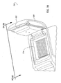
Figures 10-14 , theaccessory receiving body 300 is a beverage receptacle including a base 302 that defines one or morebeverage receiving portions 304, and alifting mechanism 310. A door/lid 306 may optionally be provided 312 to store or otherwise close out thebase 302 and thebeverage receiving portion 304 such that theaccessory receiving body 300 may be fully stowed within theconsole 100. - With continued reference to
Figures 10-14 , independent of the door, however, thebeverage receiving portion 304 is adjustable between a first, fully retracted position and a second, fully extended position, and may be infinitely adjusted to every position therebetween for presentment and use. As such, thebeverage receiving portion 304 may be accessed and used at any of the foregoing positions, including the fully retracted position. For example, if thedoor 306 is provided, thedoor 306 may be opened to allow use of thebeverage receptacle 300 in the fully retracted position. - According to an embodiment, a
motor 318 is provided to operably, vertically deploy or vertically adjust the position ofbase 302 to any of the foregoing positions. For example, thelifting mechanism 310 can include themotor 318 operably connected to aball screw 312 relative to abearing 314. Actuation of themotor 310 causes rotation of aball screw 312 relative to thebearing 314 to effect vertical movement of the base 302 to/from a stowed/presentment position. If desired, apost 316 may extend from thebase portion 14c to provide additional stability to thebase 302. According to an embodiment, theball screw 312 and post 316 may enlist the packaging of thebase 302. Specifically, the definition of twobeverage receiving portions 322 creates a space therebetween which can be adapted to vertically mount one or both of theball screw 312 and post 316 thereon. - According to the foregoing description, the condition of the base 302 (to any of the positions) may be changed responsive to, for example, movement of the
lid 306. For example, movement oflid 306 from a closed state to an open state may change (or any actuator 18) the condition of the base 302 from the fully retracted position to the presentment position (which may be, e.g., the fully extended position). - According to an embodiment, the condition of the base 302 may be changed in response to a
detector 324 in the form of an electrical contact that detects the presence of thelid 306 in a predetermined position (e.g., in an open position, a portion of the closure panel may contact the detector 324) to operably present thebase portion 302. While an electrical contact is described, it is understood that other contact sensing means might be replaced therefore. Among other examples, a photodiode or the like may be provided. - According to an embodiment, the
lid 306 is slidably disposed over thebase portion 302 and may be opened/closed manually by a force applied by a user's hand proximate alip 308 or the like. According to an embodiment, the opening/closing movement of theslidable lid 306 may trip adetector 324 to cause automatic movement of thelifting mechanism 310 by themotor 318. As illustrated, anend 326 of theslidable lid 306, may, for example, contact thedetector 324 so as to provide clearance for movement of the base 302 from a fully retracted to a presentment position. - If desired, movement of the
lifting mechanism 310 may occur when theslidable lid 306 is moved from a closed position (Figures 11 ,13 ) to a fully opened position (Figures 12 ,14 ). The fully opened position of theslidable lid 306 maybe determined by thedetector 324. As such, upon moving theslidable lid 306 to an open position, thebase portion 302 may be moved from the fully retracted position to a presentment position such that thebase portion 302 may be presented to a user until/as theslidable lid 306 is opened. - In an embodiment the
accessory receiving body 300 may include a heating/cooling device 328 for heating/cooling a beverage container, B. While a heating/cooling device 328 is disclosed, the present invention should not be limited thereby. The heating/cooling device 328 may include, for example, a fan located in anair duct 330 of a vehicle's HVAC system. An embodiment of theaccessory receiving body 300 may include a memory for programming an intermediate position of the tray 304 (i.e. a partially deployed position of the tray 304) relative a position of any one of a plurality of unique vehicle occupant settings that may or may not be associated with, for example, unique vehicle occupant settings related to vehicle seats, operator pedals, mirrors, radio station setting, or the like.
Claims (6)
- A console (10) for a vehicle, comprising
a closure panel (106, 306);
an actuator (118, 324) operably connected to the closure panel, whereupon engagement between the closure panel (106, 306) with the actuator (118, 324) instructs a vehicle accessory (102, 302) to move from a first position to at least one second position;
a motor (110, 318) connected to the actuator (118, 324); and
a lifting mechanism (108, 310) connected to the motor (110, 318) and the vehicle accessory (102, 302), wherein movement of the lifting mechanism (108, 310) is responsive to the actuation of the motor (110, 318), wherein the actuator (118, 324) is a contact sensor that causes the motor (110, 318) to drive the lifting mechanism (108, 318) to cause movement of the vehicle accessory (102, 302) from the first position to the at least one second position. - The console (10) according to claim 1, wherein the lifting mechanism (108) is defined by a scissor bridge (116) and a ball screw (112).
- The console (10) according to claim 1, wherein the lifting mechanism (318) is defined by a ball screw (312), bearing (314), and a stability post (316).
- The console (10) according to claim 1, further comprising
a body (104) defined by a floor and sidewalls extending axially from said floor, wherein said sidewalls are fixed relative to said floor, wherein the vehicle accessory (102) defines a receiving body that is movably-disposed in the body (104) for movement between said first and second positions and any position therebetween within the body (104), said receiving body (102) accessible independent of said position thereof within the body (104). - The console (10) according to claim 4, wherein the receiving body (102) further comprises
a sidewall (103) defining a depth (D); and
one or more partitioning elements (107) defining two or more stowage segments (105). - The console (10) according to claim 1, wherein the vehicle accessory (302) further comprises
a heating/cooling device (328); and
one or more beverage container receiving portions (322) in thermal communication with the heating/cooling device (328).
Applications Claiming Priority (2)
| Application Number | Priority Date | Filing Date | Title |
|---|---|---|---|
| US77524006P | 2006-02-21 | 2006-02-21 | |
| PCT/CA2007/000256 WO2007095731A1 (en) | 2006-02-21 | 2007-02-20 | Console |
Publications (3)
| Publication Number | Publication Date |
|---|---|
| EP1989079A1 EP1989079A1 (en) | 2008-11-12 |
| EP1989079A4 EP1989079A4 (en) | 2009-12-02 |
| EP1989079B1 true EP1989079B1 (en) | 2015-08-26 |
Family
ID=38436882
Family Applications (1)
| Application Number | Title | Priority Date | Filing Date |
|---|---|---|---|
| EP07701803.4A Ceased EP1989079B1 (en) | 2006-02-21 | 2007-02-20 | Console |
Country Status (4)
| Country | Link |
|---|---|
| US (1) | US7931322B2 (en) |
| EP (1) | EP1989079B1 (en) |
| CA (1) | CA2637780C (en) |
| WO (1) | WO2007095731A1 (en) |
Cited By (1)
| Publication number | Priority date | Publication date | Assignee | Title |
|---|---|---|---|---|
| US12240415B2 (en) | 2019-12-02 | 2025-03-04 | Brose Fahrzeugteile SE & Co. Kommanditgesellschaft, Coburg | Console element for a vehicle |
Families Citing this family (41)
| Publication number | Priority date | Publication date | Assignee | Title |
|---|---|---|---|---|
| US6731925B2 (en) * | 2001-10-24 | 2004-05-04 | Mouhamad Ahmad Naboulsi | Safety control system for vehicles |
| DE102008019867B4 (en) * | 2008-04-16 | 2012-12-20 | Faurecia Innenraum Systeme Gmbh | storage compartment |
| JP5262689B2 (en) * | 2008-12-24 | 2013-08-14 | 豊田合成株式会社 | Door opening / closing structure and door opening / closing device |
| WO2013142836A1 (en) * | 2012-03-23 | 2013-09-26 | B/E Aerospace, Inc. | Dynamic chilled mini-bar for aircraft passenger suite |
| DE102012208278A1 (en) * | 2012-05-16 | 2013-11-21 | Bos Gmbh & Co. Kg | Receiving device for at least one bottle or cup container in a vehicle interior |
| DE102012020479A1 (en) * | 2012-10-18 | 2014-04-24 | Faurecia Innenraum Systeme Gmbh | Device for covering a storage compartment |
| EP3126237B1 (en) * | 2014-04-03 | 2018-10-10 | Zodiac Seats US LLC | Center console side opening doors and integrated armrest cocktail tray |
| US20160024816A1 (en) * | 2014-07-25 | 2016-01-28 | Ford Global Technologies, Llc | Vehicle console security system with electrically lockable cover |
| US20150183377A1 (en) * | 2015-03-13 | 2015-07-02 | Caterpillar Inc. | Storage chamber assembly in a machine |
| JP6565532B2 (en) * | 2015-09-18 | 2019-08-28 | トヨタ紡織株式会社 | Console device |
| US9994259B2 (en) * | 2015-12-18 | 2018-06-12 | Textron Innovations Inc. | Auxiliary cargo storage bin |
| EP3192701B1 (en) | 2016-01-12 | 2018-09-26 | Lisa Dräxlmaier GmbH | Reception apparatus for a vehicle |
| CN105946729B (en) * | 2016-06-12 | 2018-07-03 | 浙江吉利控股集团有限公司 | Vehicle armrest box structure and automobile |
| US9863171B1 (en) * | 2016-09-28 | 2018-01-09 | Ford Global Technologies, Llc | Vehicle compartment |
| CN106427723A (en) * | 2016-12-09 | 2017-02-22 | 上海融康汽车设计有限公司 | Vehicle-mounted storage device with wine cabinet and refrigerator functions |
| FR3070937B1 (en) * | 2017-09-11 | 2020-10-09 | Faurecia Interieur Ind | VEHICLE TRIM ELEMENT INCLUDING A DEFORMABLE PART TO DELIMITE A FUNCTIONAL SPACE |
| US10351066B2 (en) * | 2017-11-06 | 2019-07-16 | Global Ip Holdings, Llc | Assembly capable of deploying stowed items in a passenger compartment of a vehicle |
| JP2019142336A (en) * | 2018-02-20 | 2019-08-29 | 小島プレス工業株式会社 | Console Box |
| CN108544999A (en) * | 2018-04-04 | 2018-09-18 | 罗晓阳 | A kind of suicide seat center armrest |
| CN111252002B (en) * | 2018-11-30 | 2021-12-21 | 诺博汽车零部件(平湖)有限公司 | A vehicle that is used for handrail case of vehicle and has it |
| CN111252001B (en) * | 2018-11-30 | 2021-12-17 | 诺博汽车系统有限公司 | A vehicle that is used for handrail case of vehicle and has it |
| DE102018222852A1 (en) * | 2018-12-21 | 2020-06-25 | Brose Fahrzeugteile SE & Co. Kommanditgesellschaft, Coburg | Motor vehicle assembly with a central component |
| WO2020154325A1 (en) | 2019-01-22 | 2020-07-30 | Shanghai Yanfeng Jinqiao Automotive Trim Systems Co. Ltd. | Vehicle interior component |
| US10906469B2 (en) | 2019-01-31 | 2021-02-02 | Nissan North America, Inc. | Vehicle console assembly |
| CN109910710B (en) * | 2019-03-04 | 2021-05-25 | 北京汽车股份有限公司 | Vehicle auxiliary instrument platform and vehicle |
| US11052805B2 (en) | 2019-08-30 | 2021-07-06 | Toyota Motor Engineering & Manufacturing North America, Inc. | Console bin assembly for a vehicle |
| CN110525354B (en) * | 2019-10-10 | 2021-10-29 | 上海延锋金桥汽车饰件系统有限公司 | A car interior |
| DE102019009051B3 (en) * | 2019-12-23 | 2021-06-10 | Daimler Ag | Storage compartment, in particular a lockable storage compartment, for a vehicle and vehicle |
| CN111301295B (en) * | 2020-03-19 | 2024-12-31 | 宁波舜宇精工股份有限公司 | A vehicle-mounted movable storage system |
| US12006104B2 (en) * | 2021-03-29 | 2024-06-11 | Toyoda Gosei Co., Ltd. | Double opening storage device |
| US11932156B2 (en) * | 2021-05-17 | 2024-03-19 | Ford Global Technologies, Llc | Vehicle having sliding console |
| USD997077S1 (en) * | 2021-08-20 | 2023-08-29 | Jaguar Land Rover Limited | Vehicle center console |
| US12351131B2 (en) * | 2022-04-05 | 2025-07-08 | Nissan North America, Inc. | Vehicle consoles including storage compartments |
| CN117183733A (en) * | 2022-05-31 | 2023-12-08 | 曼德电子电器有限公司 | a vehicle |
| US12296959B2 (en) * | 2022-06-08 | 2025-05-13 | B/E Aerospace, Inc. | In-seat mini-bar features |
| CN115139885B (en) * | 2022-07-11 | 2023-07-18 | 东风柳州汽车有限公司 | Handrail structures and motor vehicles |
| US12043155B2 (en) * | 2022-09-14 | 2024-07-23 | Ford Global Technologies, Llc | Vehicle console having deployable table |
| FR3147532A1 (en) * | 2023-04-05 | 2024-10-11 | Renault S.A.S. | CENTRAL CONSOLE OF A MOTOR VEHICLE |
| US20250276649A1 (en) * | 2024-02-29 | 2025-09-04 | Mullen Technologies, Inc. | Adjustable storage bins |
| USD1109196S1 (en) * | 2024-11-29 | 2026-01-13 | Weijie Zhong | Car refrigerator |
| USD1109780S1 (en) * | 2024-11-29 | 2026-01-20 | Weijie Zhong | Radiator cover for car refrigerator |
Family Cites Families (10)
| Publication number | Priority date | Publication date | Assignee | Title |
|---|---|---|---|---|
| JPH04208655A (en) * | 1990-03-12 | 1992-07-30 | Toshihiko Matsuda | Telephone rack for automobile |
| JPH05338498A (en) * | 1992-06-10 | 1993-12-21 | Toyota Autom Loom Works Ltd | Console box |
| JPH079915A (en) * | 1993-06-28 | 1995-01-13 | Kanto Auto Works Ltd | Telephone set storage device for automobile |
| JP2829340B2 (en) * | 1996-01-29 | 1998-11-25 | 三菱自動車エンジニアリング株式会社 | Car storage device |
| JP2000153738A (en) * | 1998-11-19 | 2000-06-06 | Kanto Auto Works Ltd | Console box |
| US6279977B1 (en) * | 2000-05-23 | 2001-08-28 | Jack Chen | Armrest mounted computer dock |
| AU2001273031A1 (en) * | 2000-06-28 | 2002-01-08 | Textron Automotive Company Inc. | Console heating and cooling apparatus |
| FR2816563B1 (en) | 2000-11-14 | 2003-02-28 | Sai Automotive Allibert Ind | CENTRAL MOTOR VEHICLE CONSOLE |
| JP2003165388A (en) * | 2001-11-29 | 2003-06-10 | Kasai Kogyo Co Ltd | Console box structure for vehicle |
| JP2005145384A (en) | 2003-11-19 | 2005-06-09 | Inoac Corp | Container holder |
-
2007
- 2007-02-20 EP EP07701803.4A patent/EP1989079B1/en not_active Ceased
- 2007-02-20 CA CA2637780A patent/CA2637780C/en not_active Expired - Fee Related
- 2007-02-20 US US12/280,198 patent/US7931322B2/en not_active Expired - Fee Related
- 2007-02-20 WO PCT/CA2007/000256 patent/WO2007095731A1/en not_active Ceased
Cited By (1)
| Publication number | Priority date | Publication date | Assignee | Title |
|---|---|---|---|---|
| US12240415B2 (en) | 2019-12-02 | 2025-03-04 | Brose Fahrzeugteile SE & Co. Kommanditgesellschaft, Coburg | Console element for a vehicle |
Also Published As
| Publication number | Publication date |
|---|---|
| US7931322B2 (en) | 2011-04-26 |
| EP1989079A4 (en) | 2009-12-02 |
| US20090224564A1 (en) | 2009-09-10 |
| CA2637780A1 (en) | 2007-08-30 |
| WO2007095731A1 (en) | 2007-08-30 |
| EP1989079A1 (en) | 2008-11-12 |
| CA2637780C (en) | 2015-01-27 |
Similar Documents
| Publication | Publication Date | Title |
|---|---|---|
| CA2637780C (en) | Automotive console with vehicle accessory | |
| US6640551B1 (en) | Thermal conditioning beverage container holder | |
| EP0593169B1 (en) | Swing out armrest cupholder | |
| US20230122921A1 (en) | Refrigerator | |
| EP3617631B1 (en) | Refrigerator | |
| JP4488946B2 (en) | Cup holder | |
| US6851736B1 (en) | Vehicle console | |
| US7407210B2 (en) | Climate controlled vehicle console with window | |
| JPS6064042A (en) | Icebox for automobile or similar movable device | |
| CN102686448B (en) | Tray mechanism with automatic beverage holding device | |
| WO2001037613A1 (en) | Microwave oven with removable storage cassette in dashborad of motor vehicles | |
| KR20060048632A (en) | Shock Absorber of Moving Object | |
| US7464566B2 (en) | Cooler unit with retaining control housing | |
| US20050205739A1 (en) | Cup holder with sensor | |
| US7237816B1 (en) | Automotive center console with open front face | |
| US20040135391A1 (en) | Driver-accessible storage compartments for passenger vehicles | |
| CA2565212A1 (en) | Cooled instrument panel compartment for a vehicle | |
| JP2829340B2 (en) | Car storage device | |
| JP2007514599A (en) | Variable volume console box for automobiles | |
| CN224094693U (en) | Vehicle-mounted refrigerator assembly and vehicle with same | |
| US7513549B2 (en) | Vehicle center console | |
| JP2002022353A (en) | refrigerator | |
| JP2004224236A (en) | In-vehicle warming device | |
| CN223720758U (en) | Car refrigerators and vehicles equipped with them | |
| US20250249834A1 (en) | Console module and vehicle cockpit including same |
Legal Events
| Date | Code | Title | Description |
|---|---|---|---|
| PUAI | Public reference made under article 153(3) epc to a published international application that has entered the european phase |
Free format text: ORIGINAL CODE: 0009012 |
|
| 17P | Request for examination filed |
Effective date: 20080918 |
|
| AK | Designated contracting states |
Kind code of ref document: A1 Designated state(s): DE FR GB |
|
| RIN1 | Information on inventor provided before grant (corrected) |
Inventor name: GREMS, LISA, ANN Inventor name: SHAFER, RUSSELL, P., JR. Inventor name: BECKLEY, DANIEL, V. Inventor name: O' BRIEN, TIMOTHY, F. |
|
| RBV | Designated contracting states (corrected) |
Designated state(s): DE FR GB |
|
| A4 | Supplementary search report drawn up and despatched |
Effective date: 20091104 |
|
| 17Q | First examination report despatched |
Effective date: 20100125 |
|
| DAX | Request for extension of the european patent (deleted) | ||
| GRAP | Despatch of communication of intention to grant a patent |
Free format text: ORIGINAL CODE: EPIDOSNIGR1 |
|
| INTG | Intention to grant announced |
Effective date: 20150324 |
|
| GRAS | Grant fee paid |
Free format text: ORIGINAL CODE: EPIDOSNIGR3 |
|
| GRAA | (expected) grant |
Free format text: ORIGINAL CODE: 0009210 |
|
| AK | Designated contracting states |
Kind code of ref document: B1 Designated state(s): DE FR GB |
|
| REG | Reference to a national code |
Ref country code: GB Ref legal event code: FG4D |
|
| REG | Reference to a national code |
Ref country code: DE Ref legal event code: R096 Ref document number: 602007042764 Country of ref document: DE |
|
| REG | Reference to a national code |
Ref country code: DE Ref legal event code: R082 Ref document number: 602007042764 Country of ref document: DE Representative=s name: HOESSLE PATENTANWAELTE PARTNERSCHAFT, DE Ref country code: DE Ref legal event code: R082 Ref document number: 602007042764 Country of ref document: DE Representative=s name: GLAWE DELFS MOLL PARTNERSCHAFT MBB VON PATENT-, DE Ref country code: DE Ref legal event code: R082 Ref document number: 602007042764 Country of ref document: DE Representative=s name: MUELLER & SCHUBERT PATENTANWAELTE, DE |
|
| REG | Reference to a national code |
Ref country code: FR Ref legal event code: PLFP Year of fee payment: 10 |
|
| REG | Reference to a national code |
Ref country code: DE Ref legal event code: R097 Ref document number: 602007042764 Country of ref document: DE |
|
| PLBE | No opposition filed within time limit |
Free format text: ORIGINAL CODE: 0009261 |
|
| STAA | Information on the status of an ep patent application or granted ep patent |
Free format text: STATUS: NO OPPOSITION FILED WITHIN TIME LIMIT |
|
| 26N | No opposition filed |
Effective date: 20160530 |
|
| REG | Reference to a national code |
Ref country code: DE Ref legal event code: R082 Ref document number: 602007042764 Country of ref document: DE Representative=s name: GLAWE DELFS MOLL PARTNERSCHAFT MBB VON PATENT-, DE Ref country code: DE Ref legal event code: R082 Ref document number: 602007042764 Country of ref document: DE Representative=s name: MUELLER & SCHUBERT PATENTANWAELTE, DE |
|
| REG | Reference to a national code |
Ref country code: FR Ref legal event code: PLFP Year of fee payment: 11 |
|
| REG | Reference to a national code |
Ref country code: DE Ref legal event code: R082 Ref document number: 602007042764 Country of ref document: DE Representative=s name: MUELLER & SCHUBERT PATENTANWAELTE, DE Ref country code: DE Ref legal event code: R081 Ref document number: 602007042764 Country of ref document: DE Owner name: GRUPO ANTOLIN-IRAUSA, S.A., ES Free format text: FORMER OWNER: INTIER AUTOMOTIVE INC., NEW MARKET, ONTARIO, CA |
|
| REG | Reference to a national code |
Ref country code: FR Ref legal event code: PLFP Year of fee payment: 12 |
|
| PGFP | Annual fee paid to national office [announced via postgrant information from national office to epo] |
Ref country code: FR Payment date: 20171228 Year of fee payment: 12 |
|
| PGFP | Annual fee paid to national office [announced via postgrant information from national office to epo] |
Ref country code: GB Payment date: 20180214 Year of fee payment: 12 Ref country code: DE Payment date: 20180227 Year of fee payment: 12 |
|
| REG | Reference to a national code |
Ref country code: GB Ref legal event code: 732E Free format text: REGISTERED BETWEEN 20180419 AND 20180425 |
|
| REG | Reference to a national code |
Ref country code: DE Ref legal event code: R119 Ref document number: 602007042764 Country of ref document: DE |
|
| GBPC | Gb: european patent ceased through non-payment of renewal fee |
Effective date: 20190220 |
|
| PG25 | Lapsed in a contracting state [announced via postgrant information from national office to epo] |
Ref country code: DE Free format text: LAPSE BECAUSE OF NON-PAYMENT OF DUE FEES Effective date: 20190903 Ref country code: GB Free format text: LAPSE BECAUSE OF NON-PAYMENT OF DUE FEES Effective date: 20190220 |
|
| PG25 | Lapsed in a contracting state [announced via postgrant information from national office to epo] |
Ref country code: FR Free format text: LAPSE BECAUSE OF NON-PAYMENT OF DUE FEES Effective date: 20190228 |