EP1988488A1 - Method for detecting moving objects in a blind spot region of a vehicle and blind spot detection device - Google Patents
Method for detecting moving objects in a blind spot region of a vehicle and blind spot detection device Download PDFInfo
- Publication number
- EP1988488A1 EP1988488A1 EP07008959A EP07008959A EP1988488A1 EP 1988488 A1 EP1988488 A1 EP 1988488A1 EP 07008959 A EP07008959 A EP 07008959A EP 07008959 A EP07008959 A EP 07008959A EP 1988488 A1 EP1988488 A1 EP 1988488A1
- Authority
- EP
- European Patent Office
- Prior art keywords
- images
- blind spot
- moving
- sequence
- regions
- Prior art date
- Legal status (The legal status is an assumption and is not a legal conclusion. Google has not performed a legal analysis and makes no representation as to the accuracy of the status listed.)
- Ceased
Links
Images


Classifications
-
- G—PHYSICS
- G06—COMPUTING; CALCULATING OR COUNTING
- G06V—IMAGE OR VIDEO RECOGNITION OR UNDERSTANDING
- G06V20/00—Scenes; Scene-specific elements
- G06V20/50—Context or environment of the image
- G06V20/56—Context or environment of the image exterior to a vehicle by using sensors mounted on the vehicle
- G06V20/58—Recognition of moving objects or obstacles, e.g. vehicles or pedestrians; Recognition of traffic objects, e.g. traffic signs, traffic lights or roads
-
- G—PHYSICS
- G06—COMPUTING; CALCULATING OR COUNTING
- G06T—IMAGE DATA PROCESSING OR GENERATION, IN GENERAL
- G06T7/00—Image analysis
- G06T7/20—Analysis of motion
- G06T7/223—Analysis of motion using block-matching
Definitions
- the invention relates to a method for detecting moving objects in a blind spot region of a vehicle, a blind spot detection device and to a computer program product.
- a blind spot region For vehicles it is known that even with rear view mirrors a certain region in the back of the driver of the vehicle, i.e. a blind spot region, cannot be observed easily . In case of lane changes of the vehicle dangerous situations can occur, when a moving object in the blind spot region, for instance another vehicle which is intending to passing on the nearby lane, is not observed by the driver of the vehicle.
- blind spot information systems are currently based on active sensors like radar, sonic and LIDAR (laser scanner). Infrared or stereo cameras are often used, since they provide information about the depth. Video is also considered but mainly for front view applications.
- the object is solved by a method, a blind spot detection device and a computer program produce according to claims 1, 17 and 21, respectively.
- step S100 a sequence of images is taken, e.g. by a video camera mounted on a vehicle in order to take said sequence of images of a blind spot region, situated near by the vehicle.
- Said images might also be referred to by "frames" or "fields”.
- step S102 the images of said sequence are partitioned into blocks, e.g. into blocks with 8 x 8 pixels each or with 16 x 16 pixels each, but different block sizes or block shapes are also within the scope of the present invention.
- step S104 moving blocks are identified which have moved between consecutive images of said sequence. This might be performed by evaluating the sum of absolute differences of pixel values from a block compared to corresponding blocks of subsequent images in said sequence or by evaluating other known error measures like cross correlation or mean squared errors.
- step S106 a distance and a direction of the movement is determined, e.g. by comparing the position of the moving blocks in consecutive images.
- step S108 adjacent blocks within an image are grouped, for which directions within a predetermined direction interval and distances within a predetermined distance interval have been determined.
- the predetermined direction interval and the predetermined distance interval are used to detect a movement in basically the same direction by basically a same distance.
- the predetermined intervals might be fixed or might be adaptive, e.g. to the actual directions or distances of said moving blocks._This movement might also be determined by calculating a motion vector between blocks of consecutive images and comparing said motion vectors.
- Such grouped adjacent blocks are considered a moving object in said blind spot region of the vehicle.
- grouping also the wordings “segmenting”, “segmentation” or “clustering” might be used within this description.
- At least one false alarm is determined among said moving objects and an alarm is generated only if at least one of said moving objects is no false alarm. Such false alarms might otherwise disturb the driver of a vehicle which no longer would trust the blind spot detection or might result in accidents and injuries.
- an object size of said moving object is determined and compared with a predetermined size.
- a false alarm is generated if said object size is smaller than said predetermined size.
- Small objects are not considered to be a danger for a moving vehicle so that no alarm has to be created, if only such small objects are situated in a blind spot region of the vehicle.
- Small objects below a predetermined size might be no vehicles.
- a vanishing point within said images is determined and said predetermined size depends on a distance of said moving object from said vanishing point.
- the vanishing point within an image normally is used as a point in a perspective drawing to which parallel lines appear to converge. Also in image processing this point can be determined. Objects nearby the vanishing point of an image have a smaller size within the image than objects which appear to be nearer to the vehicle.
- the vanishing point within the images is identified, an object size of the moving object is determined and a vertical distance of the moving object from said vanishing point is determined.
- Objects that are small and high above a vanishing point are normally no danger within a blind spot region of a vehicle, because these objects are not situated on a nearby lane but somewhere in the sky.
- histogram and/or edge-based statistical measures of at least one of said moving objects is calculated, evaluated and a false alarm is generated based on said step of evaluating.
- Such histogram and/or edge-based statistical measures might comprise a variance, an inter quarter range (IQR), a mean, a median, an energy, an edge energy, a uniformity, a smoothness, a third moment and/or an entropy.
- IQR inter quarter range
- Such statistical measures are known from describing images and can be used to classify moving objects. For example, road signs normally show two peaks in a histogram, one at a low luminance value and another one at a high luminance value. Road signs are considered not to be a threat for a vehicle, so that a corresponding false alarm is generated.
- the trajectory of said moving object is evaluated and the false alarm is generated based on said step of evaluating.
- Normally noise occurs for only short time instances and such noise has no trajectory.
- a detection of a moving object might only be considered if the number of trajectory points of the last frames have also been detected as moving objects and the average motion of these frames is positive.
- a size of the moving object is determined and a difference between a region surface and a convex hull of said moving object is calculated, if said size is greater than a predetermined size.
- the moving object is redefined, if said difference is above a predetermined difference. If a region of a moving object is too large and has too many concave parts, it has to be considered further, e.g. it might be_divided into a plurality of moving objects.
- said images of said sequence are split into at least two regions.
- Each region can be treated appropriately with splitting the image into at least two regions. The location where to split depends on a camera mounting angle or the vanishing point, respectively. For instance, when the image is split into two regions this location can be somewhere between the middle and one third of the image width.
- the regions should overlap slightly, to avoid border problems and obtain less abrupt changes between the regions.
- a step S200 the images are split into regions, the blocks are grouped in the regions in a step S202 and false alarm detection is adapted according to the different regions in a step S204.
- the motion estimation and the used algorithms can be adapted better to the different properties within the regions.
- the search range of the motion estimation may be adapted to the region as well as a match block size. For instance, the search range and match block size in the region with the vanishing point is lower than in the region without the vanishing point.
- the training data for a classification is different in all regions, since the perspective is changing. Obstacles in the region with the vanishing point are seen from the front, whereas obstacles in the right area, i.e. the region without the vanishing point are seen from the side.
- the different regions can be cropped or re-sampled to different resolutions, thereby reducing computation time in case of down-scaling, i.e. using less pixels, and allowing sub-pixel accuracy in case of up-scaling, i.e. calculating additional pixel value in-between the measured pixel values.
- Fig. 3 an embodiment of blind spot detection device 300 is depicted, which comprises a camera 302, a processor 304 and an indicator 306.
- the camera 302 is configured to take a sequence of images of the blind spot region.
- a monocular camera may be used for the proposed method and system.
- the processor 304 is configured to partition each of said images of said sequence into blocks, to identify moving blocks that have performed a movement between consecutive images of said sequence, to determine a direction and a distance of said movement of said moving blocks, to group adjacent moving blocks, for which directions within a predetermined direction interval and distances within a predetermined distance interval have been determined and to determine said moving objects.
- the indicator 306 is configured to indicate a dangerous situation, if a moving object in said blind spot region has been detected.
- Such indicator might be an alarm sound or an optical signal, e.g. light emitting diode (LED), which is blinking or is emitting light continuously.
- LED light emitting diode
- the blind spot detection device might also comprise active sensors 308 (showed optionally in Fig. 3 ) based on Radar, Lidar, GPS (Global Positioning System) or ultra-sonic to verify the blind spot detection devices with said active sensors.
- active sensors 308 shown optionally in Fig. 3
- Radar Lidar
- GPS Global Positioning System
- ultra-sonic ultra-sonic
- a false alarm detection unit 400 is connected to the processor 304 and to the indicator 306.
- the false alarm detection unit is configured to identify false alarms amongst said moving objects and the indicator 306 is further configured to generate an alarm if at least one of said moving objects is no false alarm.
- a further embodiment of a blind spot detection device which additionally comprises a splitting region unit 500 that is connected to the camera 302 and to the processor 304.
- the splitting region unit 500 is configured to split the images of said sequence into at least two regions.
- a top view of a blind spot region 600 of a vehicle 602, which is driving on a middle lane 603 of a three-lane road is depicted together with a left lane 604 and a right lane 606.
- a left camera 610 is mounted on a left rear view mirror 612 and a right camera 613 is mounted on a right rear view mirror 614.
- the left camera 610 has a left view angle 620 and the right camera 613 has a right view angle 622.
- a first vehicle 630 and a second vehicle 632 behind said first vehicle 630 are driving on the left lane 604.
- On the right lane 606 a third vehicle 634 is approaching the blind spot region 600.
- a "may detect area" 640 is also shown.
- the blind spot region 600 and the may detect area 640 are part of the left view angle 620 and the right view angle 622.
- a vehicle like the first vehicle 630 is inside the blind spot region 600, it is considered as a threat, no matter what velocity it has.
- a vehicle like the third vehicle 634, enters the may detect area 640 it should be detected by the blind spot detection device.
- the third vehicle 634 is considered as a threat if its velocity is too high.
- a vehicle like the second vehicle 632, that is outside the may detect area 640 is not classified as a threat but may also be tracked.
- the blind spot detection device detects vehicles 630, 632, 634 in the blind spot region 600 using a single camera sensor mounted on the own vehicle 602.
- the blind spot 600 on the left side and the right side are handled similar. If a vehicle like the first vehicle 630 is in the blind spot region 600 or other vehicles like the second vehicle 634 are about to enter the blind spot region 600 with high velocity the driver of the own vehicle 602 is warned by an optical sign (e.g. a light emitting diode LED) or by an acoustic signal if the driver intends to change the lanes.
- an optical sign e.g. a light emitting diode LED
- FIG. 7 depicts the processing steps of the proposed approach.
- a camera 610, 612 takes the sequence of images, which are afterwards preprocessed in a step S702, for example by filtering.
- a step S704 a block-based motion estimation is performed which is post-processed in a step S706.
- Blocks which move in the same direction or have the same motion vector are segmented or grouped to moving objects in a step S708.
- step S710 false alarms among the moving objects are detected.
- a box fitting step S712 is performed as an abstract model of the vehicle to which it is fitted to find contact points to a road plane for an angle/distance/velocity estimation that is performed in step S714.
- a threat or danger is identified in step S716 and a corresponding warning is initiated e.g. an acoustic signal is given.
- the angle/ distance /velocity estimation S714 helps to identify objects in a distance which is not dangerous.
- Fig. 8 an image with grouped blocks is depicted. Adjacent blocks with the same motion vector are labeled with the same numbers (1, 2, 3). Different regions are each labeled with individual numbers. It is not known after this grouping or segmenting step, if the region is either a successful detection, as it is the case for the vehicle 802 or a false alarm, as it is the case with the post 840 of a road sign 804 or a crosswalk sign 806.
- Fig. 9 a block diagram of the false alarm rejection principle is depicted.
- a plausibility check 900 is performed based on a region size and position, wherein thresholds depend on the distance to the vanishing point.
- a feature extraction 902 based on structural measures or histogram-based features and a corresponding classification 904 are used to detect false alarms that later on are rejected in order to obtain only correct segmented regions as moving objects.
- Local block-based motion estimation is used for the detection of moving objects.
- Detected moving objects are segmented into regions that outline the objects. Every contiguous region that consists of connected blocks is labeled with a different number, wherein a block is connected with the region if the region touches at least one of four (or eight) direct neighboring blocks. Afterwards, a loop through all these regions is used to consider every contiguous region individually. Afterwards a decision is made, which of these regions are false alarms. This decision is based on different plausibility factors.
- Labeled regions with fewer blocks than a certain threshold are rejected.
- the threshold depends on the distance to the vanishing point where cars or vehicles are usually uncovered behind the own obstacle. Since vehicles like cars or vans have a minimum size, detected regions that are small and high above the vanishing points (background/sky) are also rejected. Expensive filtering during post-processing of the vector field can be reduced this way.
- histogram and edge-based statistical texture measures are calculated for these areas. Based on these measures, a decision is made whether to reject the region or to further consider it.
- a classifier is used for the decision.
- Road signs for instance, are usually represented as two high peaks in the histogram, one at higher luminance value and one at a lower luminance value, respectively.
- a Haar transform usually used in face recognition
- IQR inter quartile range
- mean median
- energy edge energy as well as variance or mean in all histograms
- Spectral texture features can be used to detect periodicity and the FFT (Fast Fourier Transformation) does not need not to be computed again by using phase correlation motion estimation.
- the majority of the other false alarms can be suppressed by keeping track of their trajectory. Normally noise occurs only for short time instances and has no trajectory. For instance, a moving object is not considered a false alarm, if a number of the trajectory points of the last frames have also been detected as obstacles and the average motion of this number of frames is positive. At 30 frames per second (fps), e.g. it could be tested, whether two trajectory points of the last three frames are known. A longer history would result in a better decision but a lower response time of the system.
- fps frames per second
- a region is too large and has too many concave parts, it has to be considered further. This can easily be measured as a difference of the region services and of the convex hull surface. The histogram of the motion vectors is taken for this region and the threshold is adapted.
- Fig. 10 a block diagram of the region splitting principle is depicted.
- the images of a sequence are similar.
- Sub-pixel accuracy might be very helpful here, since motion is often between zero and one pixel.
- the sheet metals of closer cars have lower variance since they become larger (per blocks). Otherwise there is more texture near the vanishing point in the left of the image.
- the images are split into at least two regions, e.g. a left region 1202 and a right region 1204, as it is depicted in Fig. 12 . So the image is split into two regions (far and nearby region).
- Fig. 11 a top view of a split camera with slightly overlapping regions 1102 and 1104 is depicted.
- the location where to split depends on the camera mounting angle or the vanishing point 1210 respectively. For instance, this can be somewhere between the middle and one third of the image width.
- the regions might overlap slightly in order to avoid problems at the borders and for less abrupt change.
- the motion estimation and all algorithms can be adapted much better to the different properties of the two regions.
- the search range of the motion estimation may be adapted to the region.
- the search region and the match block size in the right area 1204 are lower than in the left region 1202.
- the training data for the classification is different in the regions because of the changed perspective. Obstacles as moving objects in the left area 1202 is seen from the front, whereas obstacles in the right area 1204 are seen from the side.
- an image 1300 which is split into two regions 1302 and 1304 can be further processed, by up-sampling or down-sampling the number of pixels. Since the structures in the right region 1304 are rather large the down-sampling can be performed in order to reduce computation time. Whereas in the left region 1302 an up-scaling can be performed to allow sub-pixel accuracy. The results of these regions can be later on merged again.
- the monocular passive blind spot detection is based on motion estimation (block-based) where conventional approaches usually have problems.
- false alarms can successfully rejected based on the above-mentioned criteria, and the large search range and motion model related problems can be handled using splitting of regions. So the system performance, accuracy and reliability may be improved. Additionally to the performance improvement the splitting of regions reduces the computation cost (search range).
- the monocular camera just needs one camera, whereas stereo approaches need an expensive second camera and difficult depth estimation.
- the proposed device and method is completely passive, which makes it very cheap and no interference with other active sensors can occur.
- the system can handle monochrome as well as color images.
- a camera sensor S1402 takes a sequence of images which are afterwards pre-processed in a step S1404, e.g. a filtering step. Afterwards a block-based motion estimation is performed in step S1406, wherein in a step S1408 the forward/backward motion vector combination is used, to which in a next step S1410 a median filter is applied. Border motion vectors are suppressed in a next step S1412 and a transformation of Cartesian to polar coordinates is performed in the next step S 1414.
- Implausible motion vectors are suppressed in a next step S1416 and afterwards a segmentation or a grouping of blocks with similar motion vectors is performed in a step S1418.
- the objects are closed in a step S1420 and the corresponding regions are labeled in a step S1422.
- a step S1424 a feature extraction is performed on a sequence of images taken by the camera sensor S1402 and the features are classified in the next step S 1426 with the help of training data.
- the result of the classification in step S 1426 and the result of the labeling of regions in step S1422 are combined so that for all labels a false alarm rejection step S 1428 is performed thereby taking into account a region trajectory in a step S1430.
- a box fitting in a step S1430 and a distance calculation in a step S1432 is performed for all labels so that afterwards a flat decision in a step S1434 can be performed.
Landscapes
- Engineering & Computer Science (AREA)
- Physics & Mathematics (AREA)
- General Physics & Mathematics (AREA)
- Multimedia (AREA)
- Theoretical Computer Science (AREA)
- Computer Vision & Pattern Recognition (AREA)
- Image Analysis (AREA)
- Traffic Control Systems (AREA)
- Image Processing (AREA)
- Length Measuring Devices By Optical Means (AREA)
Abstract
Description
- The invention relates to a method for detecting moving objects in a blind spot region of a vehicle, a blind spot detection device and to a computer program product.
- For vehicles it is known that even with rear view mirrors a certain region in the back of the driver of the vehicle, i.e. a blind spot region, cannot be observed easily. In case of lane changes of the vehicle dangerous situations can occur, when a moving object in the blind spot region, for instance another vehicle which is intending to passing on the nearby lane, is not observed by the driver of the vehicle.
- Thus, automotive manufacturers are currently investigating safety applications to introduce blind spot information systems to the vehicles. Such blind spot information systems are currently based on active sensors like radar, sonic and LIDAR (laser scanner). Infrared or stereo cameras are often used, since they provide information about the depth. Video is also considered but mainly for front view applications.
- It is an object of the invention to provide an improved method and device to detect moving objects in a blind spot region of a vehicle.
- The object is solved by a method, a blind spot detection device and a computer program produce according to
claims 1, 17 and 21, respectively. - Further embodiments are defined in the dependent claims.
- Further details of the invention will become apparent from a consideration of the drawings and ensuing description.
-
- Fig. 1
- shows main steps of one embodiment of the invention;
- Fig. 2
- shows steps according to a further embodiment of the invention including false alarm detection and splitting images into regions;
- Fig. 3
- shows a blind spot detection device according to one embodiment of the invention;
- Fig. 4
- shows another embodiment of a blind spot detection device with a false alarm detection unit;
- Fig. 5
- shows a further embodiment of a blind spot detection device with a splitting region unit;
- Fig. 6
- shows a top view of the vehicle equipped with a blind spot detection device according to a further embodiment of the invention;
- Fig. 7
- shows more detailed steps according to another embodiment of the invention;
- Fig. 8
- shows an exemplary diagram to illustrate false alarms;
- Fig. 9
- shows a block diagram of an embodiment of the false alarm detection unit;
- Fig. 10
- shows a block diagram of an embodiment of the splitting region unit;
- Fig. 11
- shows a top view of a further embodiment of the invention, illustrating region splitting;
- Fig. 12
- shows a schematic image in order to illustrate region splitting_in a further embodiment of the invention;
- Fig. 13
- illustrates schematically different scaling processes in different regions according to a further embodiment of the invention;
- Fig. 14
- shows a detailed block diagram of still another embodiment of the invention.
- In the following, embodiments of the invention are described. It is important to note that all described embodiments in the following may be combined in any way, i.e. there is no limitation that certain described embodiments may not be combined with others.
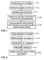
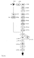
- In
Fig. 1 , in step S100 a sequence of images is taken, e.g. by a video camera mounted on a vehicle in order to take said sequence of images of a blind spot region, situated near by the vehicle. Said images might also be referred to by "frames" or "fields". - In step S102, the images of said sequence are partitioned into blocks, e.g. into blocks with 8 x 8 pixels each or with 16 x 16 pixels each, but different block sizes or block shapes are also within the scope of the present invention.
- In step S104 moving blocks are identified which have moved between consecutive images of said sequence. This might be performed by evaluating the sum of absolute differences of pixel values from a block compared to corresponding blocks of subsequent images in said sequence or by evaluating other known error measures like cross correlation or mean squared errors.
- In step S106 a distance and a direction of the movement is determined, e.g. by comparing the position of the moving blocks in consecutive images.
- In step S108, adjacent blocks within an image are grouped, for which directions within a predetermined direction interval and distances within a predetermined distance interval have been determined. The predetermined direction interval and the predetermined distance interval are used to detect a movement in basically the same direction by basically a same distance. The predetermined intervals might be fixed or might be adaptive, e.g. to the actual directions or distances of said moving blocks._This movement might also be determined by calculating a motion vector between blocks of consecutive images and comparing said motion vectors.
- Such grouped adjacent blocks are considered a moving object in said blind spot region of the vehicle. Instead the wording "grouping" also the wordings "segmenting", "segmentation" or "clustering" might be used within this description.
- In an embodiment at least one false alarm is determined among said moving objects and an alarm is generated only if at least one of said moving objects is no false alarm. Such false alarms might otherwise disturb the driver of a vehicle which no longer would trust the blind spot detection or might result in accidents and injuries.
- In a further embodiment an object size of said moving object is determined and compared with a predetermined size. A false alarm is generated if said object size is smaller than said predetermined size. Small objects are not considered to be a danger for a moving vehicle so that no alarm has to be created, if only such small objects are situated in a blind spot region of the vehicle. Small objects below a predetermined size might be no vehicles.
- In a further embodiment a vanishing point within said images is determined and said predetermined size depends on a distance of said moving object from said vanishing point. The vanishing point within an image normally is used as a point in a perspective drawing to which parallel lines appear to converge. Also in image processing this point can be determined. Objects nearby the vanishing point of an image have a smaller size within the image than objects which appear to be nearer to the vehicle.
- Objects nearby a vanishing point appear smaller and therefore are processed differently.
- In a further embodiment the vanishing point within the images is identified, an object size of the moving object is determined and a vertical distance of the moving object from said vanishing point is determined. Objects that are small and high above a vanishing point are normally no danger within a blind spot region of a vehicle, because these objects are not situated on a nearby lane but somewhere in the sky.
- In a further embodiment histogram and/or edge-based statistical measures of at least one of said moving objects is calculated, evaluated and a false alarm is generated based on said step of evaluating. Such histogram and/or edge-based statistical measures might comprise a variance, an inter quarter range (IQR), a mean, a median, an energy, an edge energy, a uniformity, a smoothness, a third moment and/or an entropy. Such statistical measures are known from describing images and can be used to classify moving objects. For example, road signs normally show two peaks in a histogram, one at a low luminance value and another one at a high luminance value. Road signs are considered not to be a threat for a vehicle, so that a corresponding false alarm is generated.
- In a further embodiment the trajectory of said moving object is evaluated and the false alarm is generated based on said step of evaluating. Normally noise occurs for only short time instances and such noise has no trajectory. A detection of a moving object might only be considered if the number of trajectory points of the last frames have also been detected as moving objects and the average motion of these frames is positive.
- In a further embodiment a size of the moving object is determined and a difference between a region surface and a convex hull of said moving object is calculated, if said size is greater than a predetermined size. The moving object is redefined, if said difference is above a predetermined difference. If a region of a moving object is too large and has too many concave parts, it has to be considered further, e.g. it might be_divided into a plurality of moving objects.
- According to a further embodiment, said images of said sequence are split into at least two regions. Normally there are very small objects with very low motion near to the vanishing point and on the other hand, there are very large and very fast moving objects in a nearer or front part of the image. So the different areas of the image have different properties. Each region can be treated appropriately with splitting the image into at least two regions. The location where to split depends on a camera mounting angle or the vanishing point, respectively. For instance, when the image is split into two regions this location can be somewhere between the middle and one third of the image width. The regions should overlap slightly, to avoid border problems and obtain less abrupt changes between the regions.
- As it is depicted in
Fig. 2 , in a step S200 the images are split into regions, the blocks are grouped in the regions in a step S202 and false alarm detection is adapted according to the different regions in a step S204. Within this embodiment the motion estimation and the used algorithms can be adapted better to the different properties within the regions. The search range of the motion estimation may be adapted to the region as well as a match block size. For instance, the search range and match block size in the region with the vanishing point is lower than in the region without the vanishing point. - In a further embodiment the training data for a classification is different in all regions, since the perspective is changing. Obstacles in the region with the vanishing point are seen from the front, whereas obstacles in the right area, i.e. the region without the vanishing point are seen from the side.
- According to a further embodiment, the different regions can be cropped or re-sampled to different resolutions, thereby reducing computation time in case of down-scaling, i.e. using less pixels, and allowing sub-pixel accuracy in case of up-scaling, i.e. calculating additional pixel value in-between the measured pixel values.
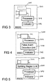
- In
Fig. 3 an embodiment of blindspot detection device 300 is depicted, which comprises acamera 302, aprocessor 304 and anindicator 306. Thecamera 302 is configured to take a sequence of images of the blind spot region. As a camera 302 a monocular camera may be used for the proposed method and system. - The
processor 304 is configured to partition each of said images of said sequence into blocks, to identify moving blocks that have performed a movement between consecutive images of said sequence, to determine a direction and a distance of said movement of said moving blocks, to group adjacent moving blocks, for which directions within a predetermined direction interval and distances within a predetermined distance interval have been determined and to determine said moving objects. - The
indicator 306 is configured to indicate a dangerous situation, if a moving object in said blind spot region has been detected. Such indicator might be an alarm sound or an optical signal, e.g. light emitting diode (LED), which is blinking or is emitting light continuously. - The blind spot detection device might also comprise active sensors 308 (showed optionally in
Fig. 3 ) based on Radar, Lidar, GPS (Global Positioning System) or ultra-sonic to verify the blind spot detection devices with said active sensors. - In
Fig. 4 a further embodiment of a blindspot detection device 300 is depicted wherein additionally a falsealarm detection unit 400 is connected to theprocessor 304 and to theindicator 306. The false alarm detection unit is configured to identify false alarms amongst said moving objects and theindicator 306 is further configured to generate an alarm if at least one of said moving objects is no false alarm. - In
Fig. 5 a further embodiment of a blind spot detection device is depicted which additionally comprises asplitting region unit 500 that is connected to thecamera 302 and to theprocessor 304. The splittingregion unit 500 is configured to split the images of said sequence into at least two regions. - In
Fig. 6 a top view of ablind spot region 600 of a vehicle 602, which is driving on amiddle lane 603 of a three-lane road is depicted together with aleft lane 604 and aright lane 606. Aleft camera 610 is mounted on a leftrear view mirror 612 and a right camera 613 is mounted on a rightrear view mirror 614. Theleft camera 610 has aleft view angle 620 and the right camera 613 has aright view angle 622. Afirst vehicle 630 and asecond vehicle 632 behind saidfirst vehicle 630 are driving on theleft lane 604. On the right lane 606 athird vehicle 634 is approaching theblind spot region 600. A "may detect area" 640 is also shown. Theblind spot region 600 and the may detectarea 640 are part of theleft view angle 620 and theright view angle 622. When a vehicle, like thefirst vehicle 630 is inside theblind spot region 600, it is considered as a threat, no matter what velocity it has. As soon as a vehicle, like thethird vehicle 634, enters the may detectarea 640 it should be detected by the blind spot detection device. Thethird vehicle 634 is considered as a threat if its velocity is too high. - A vehicle, like the
second vehicle 632, that is outside the may detectarea 640 is not classified as a threat but may also be tracked. - The blind spot detection device detects
vehicles blind spot region 600 using a single camera sensor mounted on the own vehicle 602. Theblind spot 600 on the left side and the right side are handled similar. If a vehicle like thefirst vehicle 630 is in theblind spot region 600 or other vehicles like thesecond vehicle 634 are about to enter theblind spot region 600 with high velocity the driver of the own vehicle 602 is warned by an optical sign (e.g. a light emitting diode LED) or by an acoustic signal if the driver intends to change the lanes. - The block diagram in
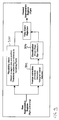
Fig. 7 depicts the processing steps of the proposed approach. Acamera - Blocks which move in the same direction or have the same motion vector are segmented or grouped to moving objects in a step S708. In the step S710 false alarms among the moving objects are detected. Afterwards a box fitting step S712 is performed as an abstract model of the vehicle to which it is fitted to find contact points to a road plane for an angle/distance/velocity estimation that is performed in step S714. Afterwards a threat or danger is identified in step S716 and a corresponding warning is initiated e.g. an acoustic signal is given. The angle/ distance /velocity estimation S714 helps to identify objects in a distance which is not dangerous.
- In
Fig. 8 an image with grouped blocks is depicted. Adjacent blocks with the same motion vector are labeled with the same numbers (1, 2, 3). Different regions are each labeled with individual numbers. It is not known after this grouping or segmenting step, if the region is either a successful detection, as it is the case for thevehicle 802 or a false alarm, as it is the case with the post 840 of aroad sign 804 or a crosswalk sign 806. - In
Fig. 9 a block diagram of the false alarm rejection principle is depicted. After a raw segmentation of the regions, including right and wrong segmentations, aplausibility check 900 is performed based on a region size and position, wherein thresholds depend on the distance to the vanishing point. Afeature extraction 902 based on structural measures or histogram-based features and acorresponding classification 904 are used to detect false alarms that later on are rejected in order to obtain only correct segmented regions as moving objects. - Local block-based motion estimation is used for the detection of moving objects. Detected moving objects are segmented into regions that outline the objects. Every contiguous region that consists of connected blocks is labeled with a different number, wherein a block is connected with the region if the region touches at least one of four (or eight) direct neighboring blocks. Afterwards, a loop through all these regions is used to consider every contiguous region individually. Afterwards a decision is made, which of these regions are false alarms. This decision is based on different plausibility factors.
- Labeled regions with fewer blocks than a certain threshold are rejected. The threshold depends on the distance to the vanishing point where cars or vehicles are usually uncovered behind the own obstacle. Since vehicles like cars or vans have a minimum size, detected regions that are small and high above the vanishing points (background/sky) are also rejected. Expensive filtering during post-processing of the vector field can be reduced this way.
- Furthermore, histogram and edge-based statistical texture measures are calculated for these areas. Based on these measures, a decision is made whether to reject the region or to further consider it. A classifier is used for the decision. Road signs, for instance, are usually represented as two high peaks in the histogram, one at higher luminance value and one at a lower luminance value, respectively. Also a Haar transform (usually used in face recognition) or other features like, for instance, variance, inter quartile range (IQR), mean, median, energy, edge energy as well as variance or mean in all histograms can be used.
- Furthermore, the statistical structural measures uniformity, smoothness, third moment and entropy are used. Spectral texture features can be used to detect periodicity and the FFT (Fast Fourier Transformation) does not need not to be computed again by using phase correlation motion estimation.
- Statistical moments of a gray-level histogram might be used to describe a texture of an image. If z denotes discrete random variables representing gray-levels in a range [0,L-1], and if p(zi), i=0,1,...,L-1 is a normalized histogram, then the following equations apply:
- A mean value m is

- A variance σ is:

- A smoothness R is:

- The third moment µ 3 is:

and describes the skewness of the histogram. - The uniformity U is:

- The entropy E is:

- The majority of the other false alarms can be suppressed by keeping track of their trajectory. Normally noise occurs only for short time instances and has no trajectory. For instance, a moving object is not considered a false alarm, if a number of the trajectory points of the last frames have also been detected as obstacles and the average motion of this number of frames is positive. At 30 frames per second (fps), e.g. it could be tested, whether two trajectory points of the last three frames are known. A longer history would result in a better decision but a lower response time of the system.
- If a region is too large and has too many concave parts, it has to be considered further. This can easily be measured as a difference of the region services and of the convex hull surface. The histogram of the motion vectors is taken for this region and the threshold is adapted.
- In
Fig. 10 a block diagram of the region splitting principle is depicted. Normally the images of a sequence are similar. There are very small cars with very low motion near to the vanishing point. Sub-pixel accuracy might be very helpful here, since motion is often between zero and one pixel. At the other hand, there are very large and very fast moving objects in the right hand side of the image. Since all objects are getting smaller with higher distance (near the left vanishing point), the variance is increasing there. The sheet metals of closer cars have lower variance since they become larger (per blocks). Otherwise there is more texture near the vanishing point in the left of the image. So the images are split into at least two regions, e.g. a left region 1202 and aright region 1204, as it is depicted inFig. 12 . So the image is split into two regions (far and nearby region). - In
Fig. 11 a top view of a split camera with slightly overlappingregions Fig. 12 ) depends on the camera mounting angle or the vanishingpoint 1210 respectively. For instance, this can be somewhere between the middle and one third of the image width. The regions might overlap slightly in order to avoid problems at the borders and for less abrupt change. - Thus, the motion estimation and all algorithms can be adapted much better to the different properties of the two regions. For instance, the search range of the motion estimation may be adapted to the region. The search region and the match block size in the
right area 1204 are lower than in the left region 1202. - The training data for the classification is different in the regions because of the changed perspective. Obstacles as moving objects in the left area 1202 is seen from the front, whereas obstacles in the
right area 1204 are seen from the side. - As it is depicted in
Fig. 13 animage 1300, which is split into tworegions right region 1304 are rather large the down-sampling can be performed in order to reduce computation time. Whereas in theleft region 1302 an up-scaling can be performed to allow sub-pixel accuracy. The results of these regions can be later on merged again. - The monocular passive blind spot detection is based on motion estimation (block-based) where conventional approaches usually have problems. With the proposed method and device false alarms can successfully rejected based on the above-mentioned criteria, and the large search range and motion model related problems can be handled using splitting of regions. So the system performance, accuracy and reliability may be improved. Additionally to the performance improvement the splitting of regions reduces the computation cost (search range).
- The monocular camera just needs one camera, whereas stereo approaches need an expensive second camera and difficult depth estimation. The proposed device and method is completely passive, which makes it very cheap and no interference with other active sensors can occur. The system can handle monochrome as well as color images.
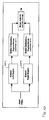
- In
Fig. 14 an overview of the proposed method is depicted. A camera sensor S1402 takes a sequence of images which are afterwards pre-processed in a step S1404, e.g. a filtering step. Afterwards a block-based motion estimation is performed in step S1406, wherein in a step S1408 the forward/backward motion vector combination is used, to which in a next step S1410 a median filter is applied. Border motion vectors are suppressed in a next step S1412 and a transformation of Cartesian to polar coordinates is performed in the next step S 1414. Implausible motion vectors are suppressed in a next step S1416 and afterwards a segmentation or a grouping of blocks with similar motion vectors is performed in a step S1418. The objects are closed in a step S1420 and the corresponding regions are labeled in a step S1422. In a step S1424 a feature extraction is performed on a sequence of images taken by the camera sensor S1402 and the features are classified in thenext step S 1426 with the help of training data. The result of the classification in step S 1426 and the result of the labeling of regions in step S1422 are combined so that for all labels a false alarm rejection step S 1428 is performed thereby taking into account a region trajectory in a step S1430. Afterwards a box fitting in a step S1430 and a distance calculation in a step S1432 is performed for all labels so that afterwards a flat decision in a step S1434 can be performed.
Claims (21)
- Method for detecting moving objects in a blind spot region of a vehicle, comprising:taking a sequence of images of said blind spot region;partitioning each of said images of said sequence into blocks;identifying moving blocks which have performed a movement between consecutive images of said sequence;determining a direction and a distance of said movement of said moving blocks;grouping adjacent moving blocks, for which directions within a predetermined direction interval and distances within a predetermined distance interval have been determined; anddetermining said moving objects based on said step of grouping.
- Method according to claim 1, further comprising:determining at least one false alarm among said moving objects; andgenerating an alarm if at least one of said moving objects is no false alarm.
- Method according to claim 2, comprising:determining an object size of said moving object;comparing said object size with a predetermined size; andgenerating said false alarm if said object size is smaller than said predetermined size.
- Method according to claim 3, further comprising:determining a vanishing point within said images, wherein said predetermined size depends on a distance of said moving object from said vanishing point.
- Method according to claim 2, further comprising:identifying a vanishing point within said images,determining an object size of said moving object;determining a vertical distance of said moving object from said vanishing point; andgenerating said false alarm, if said object size is below a predetermined object size and if said vertical distance is above a predetermined distance.
- Method according to any of claims 2 to 5, further comprising:calculating a histogram and/or edge based statistical measure of at least one of said moving objects;evaluating said histogram and/or edge based statistical measure; andgenerating said false alarm based on said step of evaluating.
- Method according to claim 6, wherein said statistical measure is a variance, an inter quartier range, a mean, a median, an energy, an edge energy, a uniformity, a smoothness, a third moment and/or an entropy.
- Method according to any of claims 2 to 7, further comprising:evaluating a trajectory of said moving object; andgenerating said false alarm based on said step of evaluating.
- Method according to any of claims 2 to 8, further comprising:determining a size of said moving object;calculating a difference between a region surface and a convex hull if said size is greater than a predetermined size; andredefining said moving objects, if said difference is above a predetermined difference.
- Method according to any of claim 1 to 9, further comprising:splitting said images of said sequence into at least two regions.
- Method according to claim 10, further comprising:using different criteria in said at least two regions in said steps of grouping said adjacent blocks.
- Method according to claim 11, wherein a different search region and/or a different matchblock size are used as different criteria.
- Method according to any of claims 10 to 12, further comprising:using different training data for identifying moving objects in said at least two regions.
- Method according to any of claims 10 to 13, further comprising:upscaling or downscaling images differently in said at least two regions.
- Method according to any of claims 2 to 9, further comprising:splitting said images of said sequence into at least two regions; andusing different thresholds for identifying false alarms within different regions.
- Method according to any of of claim 10 to 15, further comprising:splitting said images of said sequence into two regions.
- Blind spot detection device for a vehicle, comprising:a camera configured to take a sequence of images of said blind spot region;a processor configured to partition each of said images of said sequence into blocks; to identify moving blocks which have performed a movement between consecutive images of said sequence; to determine a direction and a distance of said movement of said moving blocks, to group adjacent moving blocks, for which directions within a predetermined direction interval and distances within a predetermined distance interval have been determined; and further configured to determine said moving objects; andan indicator configured to indicate a dangerous situation, if a moving object in said blind spot has been detected.
- Blind spot detection device according to claim 17, further comprising:a false alarm rejection unit, connected to said processor and to said indicator, said false alarm rejection unit being configured to identify false alarms among said moving objects; wherein said indicator is further configured to generate an alarm if at least one of said moving objects is no false alarm.
- Blind spot detection device according to any of claims 17 to 18, further comprising:a splitting region unit, configured to split said images of said sequence into at least two regions.
- Blind spot detection device according to any of claims 17 to 19, further comprising:an active sensor configured to determine a distance to said moving object.
- Computer program product, comprising a computer program code which when loaded into a processor performs the method according to any of claims 1 to 16.
Priority Applications (5)
| Application Number | Priority Date | Filing Date | Title |
|---|---|---|---|
| EP19188942.7A EP3594853A3 (en) | 2007-05-03 | 2007-05-03 | Method for detecting moving objects in a blind spot region of a vehicle and blind spot detection device |
| EP07008959A EP1988488A1 (en) | 2007-05-03 | 2007-05-03 | Method for detecting moving objects in a blind spot region of a vehicle and blind spot detection device |
| CN2008101258443A CN101303735B (en) | 2007-05-03 | 2008-04-30 | Method for detecting moving objects in a blind spot region of a vehicle and blind spot detection device |
| JP2008120555A JP5297078B2 (en) | 2007-05-03 | 2008-05-02 | Method for detecting moving object in blind spot of vehicle, and blind spot detection device |
| US12/114,239 US8040227B2 (en) | 2007-05-03 | 2008-05-02 | Method for detecting moving objects in a blind spot region of a vehicle and blind spot detection device |
Applications Claiming Priority (1)
| Application Number | Priority Date | Filing Date | Title |
|---|---|---|---|
| EP07008959A EP1988488A1 (en) | 2007-05-03 | 2007-05-03 | Method for detecting moving objects in a blind spot region of a vehicle and blind spot detection device |
Related Child Applications (1)
| Application Number | Title | Priority Date | Filing Date |
|---|---|---|---|
| EP19188942.7A Division EP3594853A3 (en) | 2007-05-03 | 2007-05-03 | Method for detecting moving objects in a blind spot region of a vehicle and blind spot detection device |
Publications (1)
| Publication Number | Publication Date |
|---|---|
| EP1988488A1 true EP1988488A1 (en) | 2008-11-05 |
Family
ID=38921773
Family Applications (2)
| Application Number | Title | Priority Date | Filing Date |
|---|---|---|---|
| EP19188942.7A Withdrawn EP3594853A3 (en) | 2007-05-03 | 2007-05-03 | Method for detecting moving objects in a blind spot region of a vehicle and blind spot detection device |
| EP07008959A Ceased EP1988488A1 (en) | 2007-05-03 | 2007-05-03 | Method for detecting moving objects in a blind spot region of a vehicle and blind spot detection device |
Family Applications Before (1)
| Application Number | Title | Priority Date | Filing Date |
|---|---|---|---|
| EP19188942.7A Withdrawn EP3594853A3 (en) | 2007-05-03 | 2007-05-03 | Method for detecting moving objects in a blind spot region of a vehicle and blind spot detection device |
Country Status (4)
| Country | Link |
|---|---|
| US (1) | US8040227B2 (en) |
| EP (2) | EP3594853A3 (en) |
| JP (1) | JP5297078B2 (en) |
| CN (1) | CN101303735B (en) |
Cited By (6)
| Publication number | Priority date | Publication date | Assignee | Title |
|---|---|---|---|---|
| CN102194239A (en) * | 2010-03-16 | 2011-09-21 | 索尼公司 | Method and system for detecting moving objects |
| WO2011131477A1 (en) * | 2010-04-23 | 2011-10-27 | Valeo Schalter Und Sensoren Gmbh | Method for warning a driver of a vehicle of the presence of objects in a blind spot region and corresponding driver assistance system |
| CN103337168A (en) * | 2013-06-04 | 2013-10-02 | 深圳市华宝电子科技有限公司 | A method, an apparatus, and a system for vehicle data acquisition |
| CN111507162A (en) * | 2019-01-30 | 2020-08-07 | 斯特拉德视觉公司 | Blind spot warning method and device based on cooperation of communication between vehicles |
| CN113807325A (en) * | 2021-11-17 | 2021-12-17 | 南京三叶虫创新科技有限公司 | Line type identification method and system based on image processing |
| US11682211B2 (en) | 2019-07-05 | 2023-06-20 | Ava Video Security Limited | Computer-implemented method |
Families Citing this family (34)
| Publication number | Priority date | Publication date | Assignee | Title |
|---|---|---|---|---|
| JP2010215787A (en) | 2009-03-17 | 2010-09-30 | Fujifilm Corp | Inorganic phosphor particle and distributed electroluminescence element using the same |
| EP2419861A1 (en) * | 2009-04-14 | 2012-02-22 | Koninklijke Philips Electronics N.V. | Key frames extraction for video content analysis |
| TW201100280A (en) * | 2009-06-19 | 2011-01-01 | Automotive Res & Testing Ct | Collision warning system for vehicle |
| US8527151B2 (en) * | 2009-12-07 | 2013-09-03 | Ford Global Technologies, Llc | Side impact safety system with blind-spot detection radar data fusion |
| JP2012221331A (en) * | 2011-04-12 | 2012-11-12 | Hitachi Ltd | Video monitoring system and number of persons estimating method |
| US8791802B2 (en) * | 2011-09-09 | 2014-07-29 | Robert Bosch Gmbh | Driver assistance system for reducing blind-spot-detection false alerts |
| EP2578464B1 (en) * | 2011-10-06 | 2014-03-19 | Honda Research Institute Europe GmbH | Video-based warning system for a vehicle |
| CN102509089B (en) * | 2011-11-29 | 2013-06-19 | 青岛科技大学 | Method for recognizing zebra crossing and measuring zebra crossing distance based on line-by-line scanning |
| US20130181860A1 (en) * | 2012-01-16 | 2013-07-18 | Ford Global Technologies, Llc | Radar based multifunctional safety system |
| JP5486031B2 (en) * | 2012-03-06 | 2014-05-07 | 本田技研工業株式会社 | Light distribution control device |
| BR112015001861B1 (en) * | 2012-07-27 | 2022-05-31 | Nissan Motor Co., Ltd | Three-dimensional object detection device |
| CN104512329B (en) * | 2013-09-27 | 2017-04-05 | 比亚迪股份有限公司 | Move backward safe householder methods, device and automobile |
| KR102233391B1 (en) * | 2014-06-16 | 2021-03-29 | 팅크웨어(주) | Electronic apparatus, control method of electronic apparatus and computer readable recording medium |
| KR101692628B1 (en) * | 2014-12-24 | 2017-01-04 | 한동대학교 산학협력단 | Method for detecting right lane area and left lane area of rear of vehicle using region of interest and image monitoring system for vehicle using the same |
| JP6543050B2 (en) * | 2015-03-06 | 2019-07-10 | 株式会社デンソーテン | Obstacle detection device and obstacle detection method |
| WO2016148322A1 (en) * | 2015-03-19 | 2016-09-22 | 삼성전자 주식회사 | Method and device for detecting voice activity based on image information |
| JP6507862B2 (en) * | 2015-06-02 | 2019-05-08 | トヨタ自動車株式会社 | Peripheral monitoring device and driving support device |
| WO2017024458A1 (en) * | 2015-08-10 | 2017-02-16 | Bayerische Motoren Werke Aktiengesellschaft | System, method and apparatus for vehicle and computer readable medium |
| JP6775285B2 (en) * | 2015-09-24 | 2020-10-28 | アルパイン株式会社 | Rear side vehicle detection alarm device |
| US10019805B1 (en) * | 2015-09-29 | 2018-07-10 | Waymo Llc | Detecting vehicle movement through wheel movement |
| US20170151909A1 (en) * | 2015-11-30 | 2017-06-01 | Razmik Karabed | Image processing based dynamically adjusting surveillance system |
| CN105667397B (en) * | 2015-12-30 | 2018-10-16 | 深圳佑驾创新科技有限公司 | Rear-view system for automobile and method |
| US9996752B2 (en) * | 2016-08-30 | 2018-06-12 | Canon Kabushiki Kaisha | Method, system and apparatus for processing an image |
| CN106251701B (en) * | 2016-09-14 | 2018-11-06 | 郑州轻工业学院 | Vehicle rearview monitor and alarm system and method based on rotation zoom multi-cam |
| DE102016218852A1 (en) * | 2016-09-29 | 2018-03-29 | Conti Temic Microelectronic Gmbh | Detection of objects from images of a camera |
| DE102016123207A1 (en) * | 2016-12-01 | 2018-06-07 | HELLA GmbH & Co. KGaA | Method for detecting a disturbance in a radar signal |
| KR102313026B1 (en) * | 2017-04-11 | 2021-10-15 | 현대자동차주식회사 | Vehicle and method for collision avoidance assist when backing up the vehicle |
| US10839266B2 (en) * | 2018-03-30 | 2020-11-17 | Intel Corporation | Distributed object detection processing |
| US10300851B1 (en) * | 2018-10-04 | 2019-05-28 | StradVision, Inc. | Method for warning vehicle of risk of lane change and alarm device using the same |
| US11037303B2 (en) * | 2019-01-31 | 2021-06-15 | Sony Corporation | Optical flow based detection and tracking of multiple moving objects in successive frames |
| KR102540574B1 (en) * | 2021-02-26 | 2023-06-08 | 이화여자대학교 산학협력단 | Method for providing augmented reality in a car using stretchable display, recording medium and device for performing the method |
| CN113205704B (en) * | 2021-03-19 | 2022-06-24 | 深圳市点创科技有限公司 | Blind area detection method and device for large vehicle and storage medium |
| CN114202965B (en) * | 2022-02-18 | 2022-05-17 | 上海齐感电子信息科技有限公司 | Driving assistance method and device, vehicle-mounted terminal and storage medium |
| CN115147726B (en) * | 2022-09-05 | 2023-03-24 | 清华大学 | City form map generation method and device, electronic equipment and readable storage medium |
Citations (2)
| Publication number | Priority date | Publication date | Assignee | Title |
|---|---|---|---|---|
| JP2000285245A (en) | 1999-03-31 | 2000-10-13 | Toshiba Corp | Method and device for preventing collision of moving body and recording medium |
| EP1562146A2 (en) | 2004-02-06 | 2005-08-10 | Sharp Kabushiki Kaisha | Image-based detection of motion in vehicle environment |
Family Cites Families (17)
| Publication number | Priority date | Publication date | Assignee | Title |
|---|---|---|---|---|
| DE4332612C2 (en) * | 1992-09-25 | 1996-02-22 | Yazaki Corp | Exterior view monitoring method for motor vehicles |
| US6488369B1 (en) * | 2000-01-31 | 2002-12-03 | Hewlett-Packard Company | Ink container configured to establish reliable electrical and fluidic connections to a receiving station |
| ES2158827B1 (en) * | 2000-02-18 | 2002-03-16 | Fico Mirrors Sa | DEVICE FOR DETECTION OF PRESENCE OF OBJECTS. |
| GB2369737B (en) | 2000-05-08 | 2005-02-02 | Automotive Tech Int | Vehicular blind spot identification and monitoring system |
| US6678413B1 (en) * | 2000-11-24 | 2004-01-13 | Yiqing Liang | System and method for object identification and behavior characterization using video analysis |
| WO2004021546A2 (en) | 2002-08-09 | 2004-03-11 | Conti Temic Microelectronic Gmbh | Means of transport with a three-dimensional distance camera and method for the operation thereof |
| FR2854692B1 (en) | 2003-05-07 | 2006-02-17 | Peugeot Citroen Automobiles Sa | OPTICAL EXPLORATION DEVICE AND VEHICLE COMPRISING SUCH A DEVICE |
| JP4628712B2 (en) * | 2004-07-09 | 2011-02-09 | 財団法人生産技術研究奨励会 | Method and apparatus for recognizing moving object on image |
| JP4039423B2 (en) * | 2004-12-14 | 2008-01-30 | 日産自動車株式会社 | Edge position calculation device, obstacle detection system |
| JP2006197034A (en) * | 2005-01-11 | 2006-07-27 | Sumitomo Electric Ind Ltd | Image recognition system, imaging apparatus, and image recognition method |
| JP4277217B2 (en) * | 2005-02-04 | 2009-06-10 | 住友電気工業株式会社 | Approaching moving body display device, system and method, and collision information providing device and method |
| JP4517393B2 (en) * | 2005-02-16 | 2010-08-04 | 株式会社デンソー | Driving assistance device |
| JP4687160B2 (en) * | 2005-03-14 | 2011-05-25 | アイシン精機株式会社 | Perimeter monitoring device |
| JP4539378B2 (en) * | 2005-03-08 | 2010-09-08 | アイシン・エィ・ダブリュ株式会社 | Driving support device and driving support method |
| JP2006318272A (en) * | 2005-05-13 | 2006-11-24 | Nissan Motor Co Ltd | Vehicular object detection device and method |
| US7804980B2 (en) * | 2005-08-24 | 2010-09-28 | Denso Corporation | Environment recognition device |
| US20080166018A1 (en) * | 2007-01-05 | 2008-07-10 | Motorola, Inc. | Method and apparatus for performing object recognition on a target detected using motion information |
-
2007
- 2007-05-03 EP EP19188942.7A patent/EP3594853A3/en not_active Withdrawn
- 2007-05-03 EP EP07008959A patent/EP1988488A1/en not_active Ceased
-
2008
- 2008-04-30 CN CN2008101258443A patent/CN101303735B/en active Active
- 2008-05-02 JP JP2008120555A patent/JP5297078B2/en active Active
- 2008-05-02 US US12/114,239 patent/US8040227B2/en active Active
Patent Citations (2)
| Publication number | Priority date | Publication date | Assignee | Title |
|---|---|---|---|---|
| JP2000285245A (en) | 1999-03-31 | 2000-10-13 | Toshiba Corp | Method and device for preventing collision of moving body and recording medium |
| EP1562146A2 (en) | 2004-02-06 | 2005-08-10 | Sharp Kabushiki Kaisha | Image-based detection of motion in vehicle environment |
Non-Patent Citations (2)
| Title |
|---|
| "Vehicle detection and tracking using the block matching algorithm", RECENT ADVANCES IN SIGNAL PROCESSING AND COMMUNICATIONS, 1999, pages 160 - 165 |
| DI STEFANO LUIGI ET AL: "Vehicle detection and tracking using the block matching algorithm", RECENT ADVANCES IN SIGNAL PROCESSING AND COMMUNICATIONS - WORLD SCIENTIFIC AND ENGINEERING ACADEMY AND SOCIETY, 1999, pages 160 - 165, XP007903993 * |
Cited By (12)
| Publication number | Priority date | Publication date | Assignee | Title |
|---|---|---|---|---|
| CN102194239A (en) * | 2010-03-16 | 2011-09-21 | 索尼公司 | Method and system for detecting moving objects |
| EP2372642A1 (en) | 2010-03-16 | 2011-10-05 | Sony Corporation | Method and system for detecting moving objects |
| US8406472B2 (en) | 2010-03-16 | 2013-03-26 | Sony Corporation | Method and system for processing image data |
| CN102194239B (en) * | 2010-03-16 | 2016-04-06 | 索尼公司 | For the treatment of the method and system of view data |
| WO2011131477A1 (en) * | 2010-04-23 | 2011-10-27 | Valeo Schalter Und Sensoren Gmbh | Method for warning a driver of a vehicle of the presence of objects in a blind spot region and corresponding driver assistance system |
| CN103337168A (en) * | 2013-06-04 | 2013-10-02 | 深圳市华宝电子科技有限公司 | A method, an apparatus, and a system for vehicle data acquisition |
| CN103337168B (en) * | 2013-06-04 | 2015-09-02 | 深圳市华宝电子科技有限公司 | A kind of vehicle data collection method, Apparatus and system |
| CN111507162A (en) * | 2019-01-30 | 2020-08-07 | 斯特拉德视觉公司 | Blind spot warning method and device based on cooperation of communication between vehicles |
| CN111507162B (en) * | 2019-01-30 | 2023-11-07 | 斯特拉德视觉公司 | Blind spot warning method and device based on cooperation of inter-vehicle communication |
| US11682211B2 (en) | 2019-07-05 | 2023-06-20 | Ava Video Security Limited | Computer-implemented method |
| CN113807325A (en) * | 2021-11-17 | 2021-12-17 | 南京三叶虫创新科技有限公司 | Line type identification method and system based on image processing |
| CN113807325B (en) * | 2021-11-17 | 2022-02-22 | 南京三叶虫创新科技有限公司 | Line type identification method and system based on image processing |
Also Published As
| Publication number | Publication date |
|---|---|
| EP3594853A2 (en) | 2020-01-15 |
| US8040227B2 (en) | 2011-10-18 |
| EP3594853A3 (en) | 2020-04-08 |
| JP2009064410A (en) | 2009-03-26 |
| CN101303735B (en) | 2013-03-20 |
| US20080309516A1 (en) | 2008-12-18 |
| CN101303735A (en) | 2008-11-12 |
| JP5297078B2 (en) | 2013-09-25 |
Similar Documents
| Publication | Publication Date | Title |
|---|---|---|
| US8040227B2 (en) | Method for detecting moving objects in a blind spot region of a vehicle and blind spot detection device | |
| Gandhi et al. | Pedestrian collision avoidance systems: A survey of computer vision based recent studies | |
| EP2993654B1 (en) | Method and system for forward collision warning | |
| US10970871B2 (en) | Estimating two-dimensional object bounding box information based on bird's-eye view point cloud | |
| EP3296923B1 (en) | A method of detecting an overtaking vehicle, related processing system, overtaking vehicle detection system and vehicle | |
| US7545956B2 (en) | Single camera system and method for range and lateral position measurement of a preceding vehicle | |
| EP3007099B1 (en) | Image recognition system for a vehicle and corresponding method | |
| US7027615B2 (en) | Vision-based highway overhead structure detection system | |
| JP3822515B2 (en) | Obstacle detection device and method | |
| CN106647776B (en) | Method and device for judging lane changing trend of vehicle and computer storage medium | |
| EP2833096B1 (en) | Method for determining a current distance and/or a current speed of a target object based on a reference point in a camera image, camera system and motor vehicle | |
| CN108162858B (en) | Vehicle-mounted monitoring device and method thereof | |
| KR101103526B1 (en) | Collision Avoidance Method Using Stereo Camera | |
| EP2741234B1 (en) | Object localization using vertical symmetry | |
| Berriel et al. | A particle filter-based lane marker tracking approach using a cubic spline model | |
| Yoneda et al. | Simultaneous state recognition for multiple traffic signals on urban road | |
| Di et al. | Forward Collision Warning system based on vehicle detection and tracking | |
| Saboune et al. | A visual blindspot monitoring system for safe lane changes | |
| Kim et al. | An intelligent and integrated driver assistance system for increased safety and convenience based on all-around sensing | |
| Riera et al. | Driver behavior analysis using lane departure detection under challenging conditions | |
| Hwang et al. | Vision-based vehicle detection and tracking algorithm design | |
| KR20070019347A (en) | device and method for detecting mobile in automated driving system | |
| Seo et al. | Use of a monocular camera to analyze a ground vehicle’s lateral movements for reliable autonomous city driving | |
| Shashidhar et al. | Computer Vision and the IoT-Based Intelligent Road Lane Detection System | |
| Shalu et al. | An intelligent lane and obstacle detection using YOLO algorithm |
Legal Events
| Date | Code | Title | Description |
|---|---|---|---|
| PUAI | Public reference made under article 153(3) epc to a published international application that has entered the european phase |
Free format text: ORIGINAL CODE: 0009012 |
|
| AK | Designated contracting states |
Kind code of ref document: A1 Designated state(s): AT BE BG CH CY CZ DE DK EE ES FI FR GB GR HU IE IS IT LI LT LU LV MC MT NL PL PT RO SE SI SK TR |
|
| AX | Request for extension of the european patent |
Extension state: AL BA HR MK RS |
|
| 17P | Request for examination filed |
Effective date: 20090408 |
|
| 17Q | First examination report despatched |
Effective date: 20090514 |
|
| AKX | Designation fees paid |
Designated state(s): DE FR GB |
|
| STAA | Information on the status of an ep patent application or granted ep patent |
Free format text: STATUS: THE APPLICATION HAS BEEN REFUSED |
|
| 18R | Application refused |
Effective date: 20190325 |