EP1988373A1 - A vectorial polarimetry method and apparatus for analysing the three-dimensional electromagnetic field resulting from an interaction between a focused illuminating field and a sample to be observed - Google Patents
A vectorial polarimetry method and apparatus for analysing the three-dimensional electromagnetic field resulting from an interaction between a focused illuminating field and a sample to be observed Download PDFInfo
- Publication number
- EP1988373A1 EP1988373A1 EP07107376A EP07107376A EP1988373A1 EP 1988373 A1 EP1988373 A1 EP 1988373A1 EP 07107376 A EP07107376 A EP 07107376A EP 07107376 A EP07107376 A EP 07107376A EP 1988373 A1 EP1988373 A1 EP 1988373A1
- Authority
- EP
- European Patent Office
- Prior art keywords
- polarisation
- light
- state
- sample
- spatial
- Prior art date
- Legal status (The legal status is an assumption and is not a legal conclusion. Google has not performed a legal analysis and makes no representation as to the accuracy of the status listed.)
- Withdrawn
Links
- 238000000034 method Methods 0.000 title claims abstract description 67
- 230000003993 interaction Effects 0.000 title claims abstract description 35
- 238000000711 polarimetry Methods 0.000 title claims description 30
- 230000005672 electromagnetic field Effects 0.000 title claims description 15
- 238000005259 measurement Methods 0.000 claims abstract description 56
- 238000009826 distribution Methods 0.000 claims abstract description 43
- 230000003287 optical effect Effects 0.000 claims description 75
- 210000001747 pupil Anatomy 0.000 claims description 38
- 238000005286 illumination Methods 0.000 claims description 36
- 238000012545 processing Methods 0.000 claims description 11
- 238000001514 detection method Methods 0.000 claims description 10
- 230000001268 conjugating effect Effects 0.000 claims description 2
- 239000000523 sample Substances 0.000 description 81
- 238000003384 imaging method Methods 0.000 description 11
- 230000000694 effects Effects 0.000 description 10
- 238000004590 computer program Methods 0.000 description 5
- 238000013500 data storage Methods 0.000 description 5
- 230000004075 alteration Effects 0.000 description 4
- 230000006870 function Effects 0.000 description 4
- 238000004458 analytical method Methods 0.000 description 3
- 238000004364 calculation method Methods 0.000 description 3
- 238000013461 design Methods 0.000 description 3
- 230000005684 electric field Effects 0.000 description 3
- 238000000572 ellipsometry Methods 0.000 description 3
- 238000005516 engineering process Methods 0.000 description 3
- 238000000386 microscopy Methods 0.000 description 3
- 230000008569 process Effects 0.000 description 3
- 238000004088 simulation Methods 0.000 description 3
- 230000002123 temporal effect Effects 0.000 description 3
- 241000282461 Canis lupus Species 0.000 description 2
- 230000005540 biological transmission Effects 0.000 description 2
- 238000004624 confocal microscopy Methods 0.000 description 2
- 239000004973 liquid crystal related substance Substances 0.000 description 2
- 101100166427 Arabidopsis thaliana CCD4 gene Proteins 0.000 description 1
- 101100139907 Arabidopsis thaliana RAR1 gene Proteins 0.000 description 1
- 101000857682 Homo sapiens Runt-related transcription factor 2 Proteins 0.000 description 1
- 102100025368 Runt-related transcription factor 2 Human genes 0.000 description 1
- 101100028790 Saccharomyces cerevisiae (strain ATCC 204508 / S288c) PBS2 gene Proteins 0.000 description 1
- 238000012512 characterization method Methods 0.000 description 1
- 238000010276 construction Methods 0.000 description 1
- 239000000835 fiber Substances 0.000 description 1
- 238000001459 lithography Methods 0.000 description 1
- 239000000463 material Substances 0.000 description 1
- 238000000399 optical microscopy Methods 0.000 description 1
- 230000005693 optoelectronics Effects 0.000 description 1
- 239000002245 particle Substances 0.000 description 1
- 238000001398 photonic force microscopy Methods 0.000 description 1
- 230000005855 radiation Effects 0.000 description 1
- 238000012795 verification Methods 0.000 description 1
- 238000011179 visual inspection Methods 0.000 description 1
Images


Classifications
-
- G—PHYSICS
- G01—MEASURING; TESTING
- G01J—MEASUREMENT OF INTENSITY, VELOCITY, SPECTRAL CONTENT, POLARISATION, PHASE OR PULSE CHARACTERISTICS OF INFRARED, VISIBLE OR ULTRAVIOLET LIGHT; COLORIMETRY; RADIATION PYROMETRY
- G01J4/00—Measuring polarisation of light
- G01J4/04—Polarimeters using electric detection means
Definitions
- the present invention relates to vectorial polarimetry.
- the invention relates to a vectorial polarimetry method with applications on microscopy, metrology, molecular imaging, and optical data storage.
- a beam of electromagnetic (EM) radiation can be represented as a vectorial field that propagates along a given direction, which will be denoted by Z in this document.
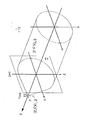
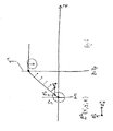
- Figure 1 is a schematic representation of a beam of light being focused by an optical system ⁇ in the region ⁇ .
- Figure 1 shows a typical beam-like field E 0 (x,y,z) that propagates along the positive direction Z.
- E 0 (x,y,z,t) can indicate possible changes in time of the field; for example induced modulations by mechanical or opto-electronic means.
- the subject of this invention is applicable to time-varying electromagnetic fields as well.
- ⁇ can be any optical system that focuses the beam, e.g. a combination of refracting and/or reflecting surfaces, a diffraction grating, etc.
- N.A. sufficiently large numerical aperture
- the general EM field possesses a longitudinal component, E 1 z (x', y', z), which is parallel to the direction of propagation of the original beam, as well as transverse components, E 1 x' (x', y', z) and E 1 y (x', y', z), parallel to the plane X'-Y' .
- E 1 z x', y', z
- E 1 y y', z
- the vectorial structure of the EM field in the focal region of a highly focused beam has been studied for several years now; its most common intended applications reside in the areas of optical storage, microscopy and scanning optical microscopy, photonic force microscopy, lithography, laser microfabrication, particle guiding or trapping, and single molecule imaging.
- the influence of the spatial distribution of the state of polarisation of the beam before it is strongly focused on the focused EM field has also been explored vastly. Perhaps one of the most common distributions is that of cylindrical vector beams, which include radial polarisation and azimuthal polarisation, but infinite number of other possibilities exist.
- Different polarisation distributions can be attained by using, for example, discrete polarisation elements like a pixelated spatial light modulator, continuous polarisation devices like the newly reported space-variant waveplate, or by simple phase and amplitude masks. Cylindrical vector fields can produce spots of focused light smaller than what scalar diffraction theory predicts. Susanne Quabis et al. published a remarkably clear and intuitive article in 2000 where they report that it is possible to produce foci of light as tight as 0.1 ⁇ (where ⁇ is used to represent the wavelength of the focused beam) using annular pupil apertures and radial polarisation.
- optical methods for storing and reading data, and for analysing materials and biological tissue are based on the illumination, detection, and processing of the optical signal at a plane that is an optical conjugate of the recorded medium or sample under observation. For this reason the information is limited by the size of the smallest spot of light on the sample that those methods can produce.
- the vast majority of the optical storage methods are based on the principle of the confocal microscope, which relies on the collection of all the energy scattered from a sample in one single detector. This does not provide any means to retrieve information of the interaction of the sample with the longitudinal component of the focused field.
- Both inventions treat the illumination and scattered field as simply composed by a finite number of rays with different angles of incidence on the sample, and do not even acknowledge that the field formed on the focusing region depends on the distribution of the state of polarisation on the entrance pupil of the illumination arm.
- the present invention provides a vectorial polarimetry apparatus and method for analysing the three-dimensional electromagnetic field resulting from an interaction between a focused illuminating beam and a sample to be observed, by characterising the distribution of the state of polarisation of light across a measurement plane.
- the apparatus of the invention comprises:
- the apparatus further comprises a light splitter through which both the illuminating light beam and the reflected light from the sample pass, and for separating the illuminating light from the reflected light.
- the light splitter comprises at least one beam splitter.
- the beam-splitter is preferably a non-polarising beam splitter.
- the light splitter may also function to reflect light from the sample toward the spatial polarisation state analyser.
- the light splitter may comprise at least one mirror that cover only a part of the cross section of the illumination as to reflect some of the light towards the sample and let some of the light go through towards the detection arm, although alternative designs are envisaged and may be employed.
- the apparatus further comprises a high numerical aperture optical collector for capturing the light that has been scattered by the sample.
- the means to control the state of polarisation at different positions across the beam width of the light beam is a spatial polarisation state control which is preferably further adapted to control the state of polarisation of both the illuminating and detected light.
- the or each spatial polarisation state analyser is adapted to measure the spatial distribution of the Stokes Vector.
- the spatial polarisation state analyser comprises means for measuring the state of polarisation at different positions on the measuring plane.
- the spatial polarisation state analyser may comprise a polarisation state analyser and an intensity detector with spatial resolution across the width of the measuring plane.
- the polarisation state analyser comprises sequential combinations of waveplates and polarisers that can measure the state of polarisation in combination with the pixelated detector.
- the apparatus may comprise a plurality of polarisation analysers, each polarisation analyser taking a light intensity measurement at a different position in the measuring plane.
- the multiple light intensity measurements may then be performed sequentially in time. Alternatively the multiple light intensity measurements may be performed simultaneously by splitting the light and using more than one optical detector.
- the detector comprises at least one pixelated detector for performing the intensity polarimetry measurements at different positions across the measuring surface.
- the at least one pixelated detector may be a CCD.
- the at least one pixelated detector may alternatively be an array of photodiodes or any other type of pixelated detector.
- the apparatus further comprises a control and processing unit.
- the control and processing unit may comprise:
- the control unit may be arranged so as to synchronise and processes the operation and the data measured by the apparatus.
- This embodiment may additionally comprise a first light splitter to direct reflected light from the sample to the at least one spatial polarisation state analyser; and a second light splitter to direct reflected light from the sample to the at least one confocal polarisation state analyser.
- said confocal polarisation state analyser is adapted to choose measurements that return from different depths within the sample.
- the first beam splitters are arranged so that light that returns from the sample is first directed towards the spatial polarisation state analyser and then to the confocal polarisation state analyser.
- the first beam splitters are arranged so that light that returns from the sample is first directed towards the confocal polarisation state analyser and then to the spatial polarisation state analyser.
- the illumination/light source may comprise at least one laser.
- the light source comprises a laser and a spatial filter in combination with a collimator lens to expand the output of the laser to produce a resulting collimated beam.
- the means to control the state of polarisation at different positions across the beam width of the light beam is a spatial polarisation state control.
- the spatial polarisation state control comprises a pixelated or continuous spatial light modulator (SLM).
- the spatial polarisation state control may comprise a liquid crystal SLM followed by any polarisation optics like polarisers, prisms and waveplates.
- the means to control the state of polarisation at different positions across the beam width of the light beam may suitably comprise discrete polarisation elements.
- discrete polarisation elements may be selected from the group comprising a pixelated spatial light modulator, continuous polarisation devices, or phase and amplitude masks.
- the polarisation state generator can act selectively across the beam's width.
- the focusing system may comprise a combination of refracting and/or reflecting surfaces.
- the focusing system may suitably comprise a diffraction grating.
- the focusing system may be arranged so as to further collect the reflected light from the sample.
- the apparatus of the invention may further comprise an optical system for selecting the optical measuring plane.
- the measuring plane may be conjugate to the entrance pupil of the focusing system.
- the optical system comprises means for optically conjugating the exit plane of the spatial polarisation state control and the entrance pupil of the focusing system.
- the optical system is preferably a 4f system.
- the optical system may comprise means for producing an image of the same entrance pupil of the focusing system onto the detector measuring plane.
- the measurement plane is an exit pupil of the optical system.
- the invention further provides a method for analysing the three-dimensional electromagnetic beam resulting from an interaction between a focused illuminating beam and a sample to be observed, by characterising the distribution of the state of polarisation of light across a measurement plane, the method comprising the steps of:
- the method further comprises the step of controlling the state of polarisation of the detected light.
- the method further comprising the step of measuring the spatial distribution of the Stokes vector.
- the method further comprises the step of measuring the state of polarisation at different positions on the pupil.
- the method may further comprise the step of taking light intensity measurements at different positions in the measuring plane. Multiple light intensity measurements may be performed sequentially in time. Alternatively, the multiple light intensity measurements may be performed simultaneously by splitting the light and using more than one optical detector.
- the method further comprises the step of processing the acquired data to estimate the three-dimensional vectorial field and/or characteristics of the observed sample.
- the method further comprises:
- a computer program comprising program instructions for causing a computer program to carry out the above method which may be embodied on a record medium, carrier signal or read-only memory.
- the invention further provides a computer program comprising program instructions for causing a computer to perform a method for analysing the three-dimensional electromagnetic beam resulting from an interaction between a focused illuminating beam and a sample to be observed, by characterising the distribution of the state of polarisation of light across a measurement plane, the method comprising the steps of:
- the invention disclosed in this document relates to an optical vectorial imaging method for reading and encoding information with applications in, for example, information storage, microscopy, molecular imaging, and optical metrology.
- the method can retrieve information of the interaction of a tightly focused light source and a sample under observation by measuring the spatial distribution of the complete or incomplete state of polarisation of light at an axial position in the detection arm of the optical system that is not necessarily a conjugate surface to the focused spot or sample under observation.
- a surface as such can be, but it is not limited to, the exit pupil of a microscope or a confocal microscope.
- This spatial distribution of the state of polarisation on the detection system will depend on the distribution of the state of polarisation across the illumination beam and the sample under observation, and this invention comprises the use of any polarimetry method to assess the effect of a sample or information storage medium on the spatial distribution of the state of polarisation across the measuring beam and/or detected beam.
- the invention we disclose in this document constitutes, but is not limited to, a novel far-field alternative to the method reported in 2005 by Ellis and Dogariu in which they describe a near-field method for characterising the polarisation properties of electromagnetic fields for which the electric field vector at a point may fluctuate in three dimensions.
- the electromagnetic field that results from the interaction of the illumination light and the sample will be, in general, a three-dimensional vector field.
- the invention disclosed in this document relates to a method to measure or estimate this resulting three-dimensional electromagnetic beam without the need of a near-field probe.
- at least one illuminating vector EM field is needed but it is possible to use more than one illumination fields (e.g. sequentially) for robustness and/or over-determination.
- the present invention is not a simple substitute to any of the aforementioned technologies; it constitutes a new method or strategy to optically inspect a sample which is capable to retrieve information that is not available to any of the current state of the art technologies. Therefore it opens a new domain for information from a sample to be read and stored.
- imaging polarimetry where the polarisation properties of different positions within a sample are measured at once using an imaging optical system.
- imaging polarimetry these different positions must be separated enough to be resolved, according to scalar theory, with the imaging system, and the measurements are made on a plane that is a conjugate to the sample.
- the present invention must not be compared to the measurement of polarisation aberrations either.
- the effect of polarisation aberrations on the size of a focusing spot has been studied for several years, but up this date there has not been a report of measuring the polarisation information on the pupil of an optical system after the light has scattered from the object under observation.
- the invention reported here presents an strategy to assess the effect of the sample on the whole three-dimensional EM vector field and for any possible configuration of the focused field.
- Z-polarised confocal microscopy a phase mask is used at the position of the pupil plane but the detection of the collected light is made with a confocal system, therefore the field that goes through the pupil phase mask is averaged and never resolved spatially.
- the optical pupil has access to the largest possible area where the longitudinal component of the field can be projected and have a significant effect.
- a spatially divided detector on this pupil with N number of pixels the dimensionality and the possibilities for optical multiplexing may increase, in principle, by a factor of N.
- a readily available 64 by 64 CCD detector and increase the dimensionality of the multiplexing scheme at least by a factor of 4096, multiplied by the detection bit-depth and the four dimensions of the state of polarisation at each detector pixel.
- the EM field in the focal region ⁇ of a focused beam depends on the initial spatial distribution of the EM field across the area covered by the original beam (before the focusing occurs), the wavelength of light, and the N.A. of the focusing system and its aberrations.
- Figures 1 and 2 are schematic representations of a beam of light being focused by an optical system ⁇ in the region ⁇ .
- Figure 2 represents a transverse cut of Figure 1 .
- the EM field has, in general, three vectorial components, which may vary as a function of the spatial coordinates x', y', and z.
- the resulting EM field can depend on the sample, including its effect on the longitudinal component of the illumination.
- the resulting EM field can depend on the orientation of the molecule's electric dipole moment, and in the case of a data storage medium, sub-diffraction-limit features of the recorded medium could also interact with any or all three vectorial components of the illumination.
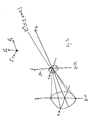
- this resulting EM field as E 2 (x',y',z ⁇ z i ) in Figs. 3a and 3b .
- Figure 3a is a schematic representation of a beam of light being focused by an optical system ⁇ in the region ⁇ and the EM field E 2 (x',y',z ⁇ z i ) that results from the interaction between the illumination and the sample.
- Figure 3b is a schematic representation of a beam of light being focused by an optical system ⁇ in the region ⁇ and the EM field E 2 (x',y',z ⁇ z i ) that results from the interaction between the illumination and the sample. This figure represents a transverse cut of Fig. 3a .
- the subject invention includes a new method to study, measure, analyse, detect, etc., this EM field, E 2 (x',y',z ⁇ z i ), that results from the interaction of the illumination field and the sample.
- the method consists on the assessment of the spatial or spatio-temporal distribution of the state of polarisation on a plane that is not necessarily a conjugate to the focal region ⁇ .
- the exit pupil of the optical system is a good example of such a plane, or any other plane optically near the exit pupil.
- the exit pupil in Optics is defined as the image of the aperture stop of an optical system as seen through the optical system from the image space; this is a good example of a plane to measure the distribution of the state of polarisation but other planes where the projection of the longitudinal component of the focused field and/or the field that results from the interaction of the illumination with the sample is not negligible.
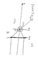
- Figure 4 shows a schematic representation of an example of such a measurement in the particular case where the collecting (imaging) arm is facing the illumination arm, which results in a transmission configuration.
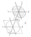
- the invention also comprises reflection configurations, for which the illumination focusing objective acts as a collector as well, like in Fig. 5 or in any reflection-type microscope system.
- the measuring plane ⁇ as the pupil plane because the optical pupil of the system is an excellent candidate for the measurements, but ⁇ can be any other surface where a projection of the longitudinal component of the focused field is not negligible; see Fig. 6 .
- Figure 4 is a schematic representation of the light that results from the interaction of a focused field and a sample as it propagates through an optical system.
- This invention relates to the idea of completely characterising the distribution of the state of polarisation of light across a plane like the exit pupil ⁇ .
- the crosses represent examples of sample points but the distribution can be measured using any geometry or any pixel shape and size.
- a suitable measurement surface ⁇ can be any surface in the optical system where the projection of the longitudinal component of the focused field does not have a negligible magnitude for the polarimetry measurement to be meaningful.
- the measurement of the state of polarisation at each position on the pupil ⁇ can be made by any existing or to-be-developed polarimetry or ellipsometry method.
- the spatial discrimination of the distribution of the state of polarisation can be performed with a spatially divided detector like, for example, a CCD, which divides the measuring plane in small pixel elements of arbitrary chosen shape and size.
- a CCD which divides the measuring plane in small pixel elements of arbitrary chosen shape and size.
- any Polarisation State Analyser PSA
- PSA Polarisation State Analyser
- more than one pixelated detectors can be used depending on the polarimetry method of choice.
- the assessment of the state of polarisation of the light can be done routinely nowadays using well established polarimetry methods.
- the most important claim of this invention is that by measuring and analysing the distribution of the state of polarisation on the pupil plane it is possible to retrieve information of the three-dimensional vectorial EM interaction of the illumination focused field and the sample, and no one has reported this before. Furthermore, this analysis can be repeated more than one time using different illumination fields, simply by engineering the distribution of the state of polarisation on the entrance pupil of the illumination arm, as explained above.
- Figure 7 a shows a vectorial polarimetry apparatus according to one embodiment of the present invention.
- the apparatus has a reflection configuration. Its basic components are a spatial polarisation state generator 102, a light splitter 104, a focusing system 106, a spatial polarisation state analyser 108 and a control and processing unit 110.
- the characteristics and design of the sample 112 can be part of the apparatus in an optical data storage embodiment, see Fig. 11 .
- the spatial polarisation state generator 102 comprises a light (illumination) source and a means to control the state of polarisation at different positions across the beam width. This can be achieved by, for example, discrete polarisation elements like a pixelated spatial light modulator, continuous polarisation devices like a space-variant waveplate, or by simple phase and amplitude masks.
- the light splitter is any device that can separate the illumination arm from the detection arm. This can be easily done by light beam splitters, for example a cube, a pellicle, or a plate. Another alternative is to use mirrors that cover only a part of the cross section of the illumination as to reflect some of the light towards the sample and let some of the light go through towards the detection arm. The use of any other light splitter is also comprised in this invention.
- the focusing system ⁇ in this configuration is the responsible of bringing light to a focus, and also acts as the collector of the light that returns from the sample.
- this system can be a combination of refracting and/or reflecting surfaces, a diffraction grating or any other suitable optical system.
- the only requirement is that the numerical aperture is high enough as to produce a tight focus with a suitable three-dimensional vectorial structure at the focus.
- the spatial polarisation state analyser comprises a polarisation sensitive detector that can measure the state of polarisation at different positions across the width of the measuring plane ⁇ .
- the measurement of the spatial distribution of the Stokes Vector is a suitable type of measurement that the spatial polarisation state analyser can perform. This particular type of measurement can be done by any well known and established, or newly developed, polarimetry technique; we repeat that the requirement for this invention is that the state of polarisation is measured, calibrated, and estimated at different positions across the measuring plane ⁇ .
- this measurement at each position in ⁇ requires typically four light intensity measurements, each using a different polarisation analyser; the measurements can be done sequentially in time, or simultaneously by splitting the light, using different polarisation analysers, and more than one optical detector.
- a pixelated detector - for example a CCD, or an array of photodiodes - can be an adequate means to perform the intensity polarimetry measurements at different positions across the measuring surface ⁇ . If light is split, then more than one pixelated detectors can be necessary.
- the control and processing unit 110 comprises a means to control the spatial polarisation state generator, synchronise the measurements of the spatial polarisation state analyser, and process the acquired data to estimate the three-dimensional vectorial field and/or characteristics of the observed sample.
- Figure 7b shows a vectorial polarimetry apparatus in the transmission configuration according to the present invention. Its basic components are similar to the apparatus in the reflection configuration, but the light splitter is not strictly necessary and a separate high numerical aperture optical collector ⁇ ' 114 is necessary to capture the light that has been scattered by the sample. The description for the rest of the components is the same as in the reflection configuration example shown in Figure 7a ).
- Figure 7c shows a vectorial polarimetry apparatus in the reflection configuration, in accordance with a further embodiment of the invention, that uses the spatial polarisation state control on the illumination and the detection arms.
- the apparatus comprises an illumination source 116 and separate spatial polarisation state control 118.
- the apparatus further comprises a spatial polarisation state detector 120.
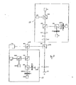
- Figure 8 shows a further embodiment of a vectorial polarimetry apparatus according to the present invention.
- the illumination light source 116 can be a laser which is then expanded by means of, for example, a typical spatial filter combination 122 with a collimator lens 124.
- the resulting beam 126 which can be collimated, passes through a spatial polarisation state control device 128.
- This device can be a pixelated or continuous spatial light modulator (SLM); an example of it is a liquid crystal SLM followed by any polarisation optics like polarisers, prisms and waveplates.
- SLM pixelated or continuous spatial light modulator
- the aim, as mentioned before, is to produce a beam with controlled state of polarisation at different positions across its width.
- the beam then passes through a beam-splitter 104 which can be a non-polarising beam splitter, and is reflected towards the sample 112.
- An optional optical system 130 for example a 4f system, between the beam-splitter and the focusing system ⁇ can be used to select the optical plane that is conjugate to the entrance pupil of the focusing system ⁇ 106.
- one possible choice is to optically conjugate the exit plane of the spatial polarisation state control and the entrance pupil of the focusing system ⁇ .
- this optional optical system can produce an image of the same entrance pupil of the focusing system ⁇ onto the detector measuring plane ⁇ .
- the focusing system can be described as per the previous examples.
- the state of polarisation at different positions on the pupil will be measured by the spatial polarisation state analyser 108.
- This can be formed by a polarisation state analyser 132 and an intensity detector 134 with spatial resolution across the width of the measuring plane ⁇ .
- the polarisation state analyser 132 in this case can be formed by sequential combinations of waveplates and polarisers that can measure the state of polarisation in combination with the pixelated detector.
- a control unit 110 synchronises and processes the operation and the data measured by the apparatus.
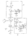
- Figure 9 shows a further embodiment of a vectorial polarimetry apparatus in accordance with the present invention.
- This embodiment comprises a confocal polarisation state analyser 136.
- Light generate by the spatial polarisation state generator (PSG) 102 passes through beam-splitters BS1 204 and BS2 304 before reaching L1, which is the focusing system ⁇ 206.
- L1 which is the focusing system ⁇ 206.
- the light that returns from the sample is collected again by L1 206 and then separated by BS2 304 again.
- Spatial polarisation state analyser 138 a division-of amplitude polarimeter (DOAP) with pixelated detectors, CCD1 - CCD4 140-143 that measure the state of polarisation at different positions across the measuring surface ⁇ , which is now a set of four optically identical surfaces for simultaneous measurements.
- BS5 404 and BS6 504 are beam-splitters that can be non-polarising.
- PBS2 146 is a polarising beam splitter that directs two orthogonal state of polarisation to pixelated detectors CCD1140 and CCD2 141, for example, linear horizontal and linear vertical.
- QWP2 148 can be a linear quarter-waveplate oriented at 45 degrees with respect to linear polariser P4 150, and P3 152 can be linear polariser at 45 degrees.
- DOAP can measure the Stokes vector at all pixels in the detectors, provided they are registered appropriately, instantaneously. It is another example of a Spatial polarisation state analyser, but other types may be used.
- the light that returns from the sample and passes through BS2 304 without being reflected will pass though BS1 204 again and then enter a confocal polarisation state analyser 136, which can be used to choose measurements that return from different depths within the sample.
- Figure 10 shows a further embodiment of a vectorial polarimetry apparatus in accordance with the present invention.
- the difference between this embodiment and the previous embodiment is that in the embodiment shown in figure 9 , the light that returns from the sample 112 is first directed towards the confocal polarisation state analyser 138 by beam-splitter 704 and then to the spatial polarisation state analyser 136 by beam-splitter 604, but the operation is the same. Through this difference it is possible to choose which polarisation state analyser receives more of the light that returns from the sample 112.
- possible shapes of "pits" in the storage media that can be used to multiplex data are geometrical scatterers like, but not limited to, the examples of the sample ⁇ 112 shown in Figure 11 .
- the orientation, size, and shape, for example, of the scatterers 160 could be used to store the multiplexed information.
- the amount of multiplexed data will depend on the number of pixels used in the spatial polarisation state analyser, signal-to-noise-ratio, and incident distribution of the state of polarisation generated by the spatial polarisation state generator in the apparatus.
- the shape, size, orientation, depth, height, etc of small manufactured samples can be used to store information, which can then be read using a method and apparatus according to the present invention. This is an example of means to store information but may not be limited to the features mentioned as long as the feature being used has an effect on the distribution of the state of polarisation across the measuring plane.
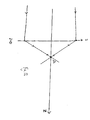
- Figure 12 is a schematic representation of the geometry used in to make the numerical calculations reported in this disclosure.
- the measurement plane ⁇ collected the light scattered back by the point scatterer.
- Richards and Wolf method was used to calculate the EM field in the focused region ⁇ and then calculated the EM field that results from the interaction of this field and a point-scatterer on the optical axis in the center of the focusing region ⁇ . We call this field the scattered field.
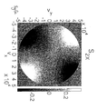
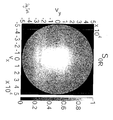
- Figures 13a - 13d show the spatial distribution of the four Stokes parameters of the scattered field behind the aperture of the collector/objective lens.
- Figures 13a to 13d show numerical calculations of the spatial distribution of the four Stokes parameters (So, S 1 , S 2 , S 3 ) behind the aperture of the collector/objective lens of the field scattered by a point scatterer.
- the scale of coordinate axes v x and v y is in optical units with respect to the N.A. ⁇
- We repeat that the measurement of the Stokes parameters can be made with any polarimetry or ellipsometry method.
- the scale of coordinate axes v x and v y is in optical units with respect to the N.A. of 0.85. Note that even though once the scattered light has been collected by the lens into a beam-like field again the nature of the three-dimensional EM field interaction with the sample is present as a non-homogeneous distribution of the state of polarisation across the aperture. This is the type of information retrieval that this invention is related to.
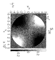
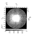
- Figure 14 we show the result of another simulation; this time we chose uniformly distributed right-circular polarisation across the illumination beam instead of horizontal linearly polarised. The rest of the simulation parameters were chosen to be the same. It can be seen clearly, even by visual inspection only, that the two scenarios can be easily distinguished.
- Figure 14 shows numerical calculations of the spatial distribution of the 4 Stokes parameters (S 0 , S 1 , S 2 , S 3 ) behind the aperture of the collector/objective lens of the field scattered by a point scatterer.
- An important application of the subject invention is in the area of optical data storage.
- Different sub-wavelength features in a sample which are readily available by means of micro-lithographic methods, can produce different EM field distributions on the pupil of an optical system in the domain of this invention. These patterns can be seen as signature that can be used to store information. Since it is not necessary that the structure of the sample is larger than the diffraction limited spot, this invention provides with a new way to multiplex optical data.
- the present invention can be coupled to confocal measurements if depth discrimination within a sample are sought for. By weighting the signals measured on the pupil with the intensity collected in a confocal aperture one could acquire "confocal far-field three-dimensional optical polarimetry" measurements, or images, if the sample is scanned with the illumination spot.
- the invention also extends to computer programs, particularly computer programs stored on or in a carrier adapted to bring the invention into practice.
- the program may be in the form of source code, object code, or a code intermediate source and object code, such as in partially compiled form or in any other form suitable for use in the implementation of the method according to the invention.
- the carrier may comprise a storage medium such as ROM, e.g. CD ROM, or magnetic recording medium, e.g. a floppy disk or hard disk.
- the carrier may be an electrical or optical signal which may be transmitted via an electrical or an optical cable or by radio or other means.
Abstract
A method and apparatus for analysing the three-dimensional electromagnetic beam resulting from an interaction between a focused illuminating beam and a sample to be observed, by characterising the distribution of the state of polarisation of light across a measurement plane, the method comprising the steps of generating a beam of illuminating light; controlling the state of polarisation at different positions across the beam width of the light beam; focussing said illuminating light beam to a focus, wherein said focus is a tight focus and said focused light has a suitable three-dimensional vectorial structure at the focus; detecting and measuring the state of polarisation of the reflected light at different positions across the width of the measurement plane to retrieve information on the three dimensional vectorial electromagnetic interaction of the illuminated focused field and the sample.
Description
- The present invention relates to vectorial polarimetry. In particular the invention relates to a vectorial polarimetry method with applications on microscopy, metrology, molecular imaging, and optical data storage.
- A beam of electromagnetic (EM) radiation can be represented as a vectorial field that propagates along a given direction, which will be denoted by Z in this document.
Figure 1 is a schematic representation of a beam of light being focused by an optical system Σ in the region Ω .Figure 1 shows a typical beam-like field E0(x,y,z) that propagates along the positive direction Z. A more explicit representation of the field would require a temporal variable, E0(x,y,z,t), that can indicate possible changes in time of the field; for example induced modulations by mechanical or opto-electronic means. The subject of this invention is applicable to time-varying electromagnetic fields as well. For simplicity, in the rest of the document, the possible temporal variation of the fields will be assumed as implicit, and the temporal variable will not be included in the text. If a beam of light propagates through an isotropic medium, its EM vector field, at every position within the beam, lies on a plane (X-Y) that is perpendicular to the direction of propagation. In other words, for a beam-like field there is no component of the EM field along the direction of propagation Z; or there is no longitudinal component of the EM field. InFig. 1 , E0(x,y,z) is the representation of an example of such a beam-like field. - When light is brought to a focus by an optical system (e.g. Σ at z=0 in
Fig. 1 , wherein Σ can be any optical system that focuses the beam, e.g. a combination of refracting and/or reflecting surfaces, a diffraction grating, etc.) with a sufficiently large numerical aperture (N.A.), the EM field (E1(x',y',z)) that is formed in the region Ω around the focus no longer necessarily lies on a single plane perpendicular to the direction of propagation of the original beam. Near the focal region Ω the general EM field possesses a longitudinal component, E1 z(x', y', z), which is parallel to the direction of propagation of the original beam, as well as transverse components, E1 x' (x', y', z) and E1 y (x', y', z), parallel to the plane X'-Y' . Note that the primed coordinates x' and y' are the same as x and y. We choose to use the primed coordinate system around the focal region to emphasize the difference between the beam-like field and the focused field. The total longitudinal component of the focused field depends on the state of polarisation of the original beam, or more accurately, on the distribution of the state of polarisation across a transverse section of the original beam; inFig. 1 , for example, the field distribution E0(x, y, z=0) at z=0. This became well known since the publication of a seminal paper in 1959 by Richards and Wolf where they analysed a focused field in an aplanatic system, and is also true as long as the N.A. is sufficiently large, even if the system is not aplanatic; for example in the presence of optical aberrations, or dielectric interfaces. The vectorial structure of the EM field in the focal region of a highly focused beam has been studied for several years now; its most common intended applications reside in the areas of optical storage, microscopy and scanning optical microscopy, photonic force microscopy, lithography, laser microfabrication, particle guiding or trapping, and single molecule imaging. The influence of the spatial distribution of the state of polarisation of the beam before it is strongly focused on the focused EM field has also been explored vastly. Perhaps one of the most common distributions is that of cylindrical vector beams, which include radial polarisation and azimuthal polarisation, but infinite number of other possibilities exist. Different polarisation distributions can be attained by using, for example, discrete polarisation elements like a pixelated spatial light modulator, continuous polarisation devices like the newly reported space-variant waveplate, or by simple phase and amplitude masks. Cylindrical vector fields can produce spots of focused light smaller than what scalar diffraction theory predicts. Susanne Quabis et al. published a remarkably clear and intuitive article in 2000 where they report that it is possible to produce foci of light as tight as 0.1λ (where λ is used to represent the wavelength of the focused beam) using annular pupil apertures and radial polarisation. Most of the efforts to tailor or engineer the distribution of the state of polarisation of a beam have been aimed to produce the smallest possible spot of light at the region of focus, and hence achieve what is commonly referred to as imaging beyond the diffraction limit. These schemes referred to as sub-diffraction limit imaging methods base their so-called "super-resolution" on detecting the intensity of all the light that has been scattered from a spot of light that is smaller to what scalar diffraction predicts. Important attempts have also been made to determine the three-dimensional orientation of single molecules. - Reference is made to the method reported in 2005 by Ellis and Dogariu in which they describe a near-field method for characterising the polarisation properties of electromagnetic fields for which the electric field vector at a point may fluctuate in three dimensions. In their publication they model and measure the superposition of three orthogonal laser light beams generated by three independent laser sources, which form a three-dimensional electromagnetic field at the point where they intersect. Ellis and Dogariu used 9 different configurations of a near-field detector that consisted of two opposing near-field sharp fibers placed in close proximity to the point of the intersection of the beams. The relevance of their work to this disclosure is the experimental verification, although by means of a near-field method, that there exists important and retrievable information in a three-dimensional electromagnetic field, they call this retrieval of polarisation information: "three-dimensional optical polarimetry".
- We described above the principles of how it is possible to engineer a three-dimensional electromagnetic field by means of focusing a beam of light with a chosen distribution of the state of polarisation across its waist, using an optical system with a sufficiently high N.A.. If such an illuminating focused beam impinges on a sample to be observed, i.e. optically analysed, the electromagnetic field that results from the interaction of the illumination light and the sample will be, in general, a three-dimensional vector field.
- Most of the current optical methods for storing and reading data, and for analysing materials and biological tissue are based on the illumination, detection, and processing of the optical signal at a plane that is an optical conjugate of the recorded medium or sample under observation. For this reason the information is limited by the size of the smallest spot of light on the sample that those methods can produce. The vast majority of the optical storage methods are based on the principle of the confocal microscope, which relies on the collection of all the energy scattered from a sample in one single detector. This does not provide any means to retrieve information of the interaction of the sample with the longitudinal component of the focused field.
- There are other methods that not only detect the total intensity of the scattered field but they also analyse the state of polarisation at a plane that is a conjugate to the sample. Such is the case of the multiplexing method by Török et al., where they suggest the use of a polarising beam-splitter to multiplex the signal encoded in the angular orientation of a step-like feature in an optical disk. By using polarisation they claim that it is possible to detect different orientations of the step-like feature. There is no account in the patent by Török et al. of the influence of the longitudinal component of the scattered field on the pupil of the optical system.
- Only two patents and one scientific publication have made use of a limited part of the information of the state of polarisation on the pupil plane to assess optical properties of the object under observation. In the patent by Zhan and Legger and the one by Gold et al. only homogeneous linearly polarised light is used, which means that the longitudinal component of the electric field is zero at the center of the focused spot (on the optical axis), and negligible at positions near the optical axis. Hence, the EM field used to illuminate the sample is not considered as a three dimensional field. The patents by Zhan and Legger and by Gold et al. relate to an incomplete polarimetry method known as ellipsometry. Both inventions treat the illumination and scattered field as simply composed by a finite number of rays with different angles of incidence on the sample, and do not even acknowledge that the field formed on the focusing region depends on the distribution of the state of polarisation on the entrance pupil of the illumination arm.
- One scientific paper has been published where the authors claim they can simulate the assessment of the effect of a sample on the longitudinal component of a focused field. The technique reported is called "Z-polarised confocal microscopy". The biggest limitation of this technique is that it only attempts to measure the effect of the sample on the longitudinal component of the field and no strategy is mentioned as to how to measure the effect of the sample on the transverse components of the focused field.
- It is an object of the invention to provide a new method or strategy to optically inspect a sample which is capable to retrieve information that is not available to any of the current state of the art technologies. Such a method or strategy would open a new domain for information from a sample to be read and stored.
- It is a further object of the invention to provide a method to measure or estimate a three-dimensional electromagnetic beam without the need of a near-field probe.
- Accordingly, the present invention provides a vectorial polarimetry apparatus and method for analysing the three-dimensional electromagnetic field resulting from an interaction between a focused illuminating beam and a sample to be observed, by characterising the distribution of the state of polarisation of light across a measurement plane.
- The apparatus of the invention comprises:
- a) a spatial polarisation state generator comprising an illumination source for generating a beam of light and means to control the state of polarisation at different positions across the beam width of the light beam;
- b) a focusing system for bringing said illuminating light beam to a focus, wherein the focusing system has a numerical aperture high enough as to produce a tight focus with a suitable three-dimensional vectorial structure at the focus; and
- c) at least one spatial polarisation state analyser comprising a polarisation sensitive detector that can measure the state of polarisation of the light from the sample at different positions across the width of the measuring plane to retrieve information on the three dimensional vectorial electromagnetic interaction of the illuminated focused field and the sample.
- According to one embodiment of the invention the apparatus further comprises a light splitter through which both the illuminating light beam and the reflected light from the sample pass, and for separating the illuminating light from the reflected light.
- Preferably the light splitter comprises at least one beam splitter. The beam-splitter is preferably a non-polarising beam splitter. The light splitter may also function to reflect light from the sample toward the spatial polarisation state analyser.
- The light splitter may comprise at least one mirror that cover only a part of the cross section of the illumination as to reflect some of the light towards the sample and let some of the light go through towards the detection arm, although alternative designs are envisaged and may be employed.
- According to one embodiment of the invention, the apparatus further comprises a high numerical aperture optical collector for capturing the light that has been scattered by the sample.
- Preferably the means to control the state of polarisation at different positions across the beam width of the light beam is a spatial polarisation state control which is preferably further adapted to control the state of polarisation of both the illuminating and detected light.
- In accordance with one embodiment of the invention, the or each spatial polarisation state analyser is adapted to measure the spatial distribution of the Stokes Vector.
- Preferably, and in accordance with any embodiment, the spatial polarisation state analyser comprises means for measuring the state of polarisation at different positions on the measuring plane. The spatial polarisation state analyser may comprise a polarisation state analyser and an intensity detector with spatial resolution across the width of the measuring plane.
- According to one embodiment of the invention, the polarisation state analyser comprises sequential combinations of waveplates and polarisers that can measure the state of polarisation in combination with the pixelated detector.
- The apparatus may comprise a plurality of polarisation analysers, each polarisation analyser taking a light intensity measurement at a different position in the measuring plane. The multiple light intensity measurements may then be performed sequentially in time. Alternatively the multiple light intensity measurements may be performed simultaneously by splitting the light and using more than one optical detector.
- Preferably the detector comprises at least one pixelated detector for performing the intensity polarimetry measurements at different positions across the measuring surface. The at least one pixelated detector may be a CCD. The at least one pixelated detector may alternatively be an array of photodiodes or any other type of pixelated detector.
- Preferably the apparatus further comprises a control and processing unit.
- The control and processing unit may comprise:
- means for controlling the spatial polarisation state generator,
- means for synchronising the measurements of the spatial polarisation state analyser, and
- means for processing the acquired data to estimate the three-dimensional vectorial field and/or characteristics of the observed sample.
- The control unit may be arranged so as to synchronise and processes the operation and the data measured by the apparatus.
- According to one embodiment of the invention the apparatus of the invention further comprises:
- at least one spatial polarisation state analyser comprising a polarisation sensitive detector that can measure the state of polarisation of the reflected light at different positions across the width of the measurement plane; and
- at least one confocal polarisation state analyser comprising a polarisation sensitive detector that can measure the state of polarisation at different positions across the width of the measuring plane to retrieve information on the three dimensional vectorial electromagnetic interaction of the illuminated focused field and the sample.
- This embodiment may additionally comprise a first light splitter to direct reflected light from the sample to the at least one spatial polarisation state analyser; and a second light splitter to direct reflected light from the sample to the at least one confocal polarisation state analyser.
- Preferably said confocal polarisation state analyser is adapted to choose measurements that return from different depths within the sample.
- According to one embodiment, the first beam splitters are arranged so that light that returns from the sample is first directed towards the spatial polarisation state analyser and then to the confocal polarisation state analyser.
- According to a further embodiment, the first beam splitters are arranged so that light that returns from the sample is first directed towards the confocal polarisation state analyser and then to the spatial polarisation state analyser.
- The illumination/light source may comprise at least one laser. According to one embodiment, the light source comprises a laser and a spatial filter in combination with a collimator lens to expand the output of the laser to produce a resulting collimated beam.
- Preferably the means to control the state of polarisation at different positions across the beam width of the light beam is a spatial polarisation state control. Preferably the spatial polarisation state control comprises a pixelated or continuous spatial light modulator (SLM). The spatial polarisation state control may comprise a liquid crystal SLM followed by any polarisation optics like polarisers, prisms and waveplates.
- The means to control the state of polarisation at different positions across the beam width of the light beam may suitably comprise discrete polarisation elements. Such discrete polarisation elements may be selected from the group comprising a pixelated spatial light modulator, continuous polarisation devices, or phase and amplitude masks.
- Preferably the polarisation state generator can act selectively across the beam's width.
- The focusing system may comprise a combination of refracting and/or reflecting surfaces. The focusing system may suitably comprise a diffraction grating.
- The focusing system may be arranged so as to further collect the reflected light from the sample.
- The apparatus of the invention may further comprise an optical system for selecting the optical measuring plane. The measuring plane may be conjugate to the entrance pupil of the focusing system. Preferably the optical system comprises means for optically conjugating the exit plane of the spatial polarisation state control and the entrance pupil of the focusing system. The optical system is preferably a 4f system.
- The optical system may comprise means for producing an image of the same entrance pupil of the focusing system onto the detector measuring plane. Preferably the measurement plane is an exit pupil of the optical system.
- The invention further provides a method for analysing the three-dimensional electromagnetic beam resulting from an interaction between a focused illuminating beam and a sample to be observed, by characterising the distribution of the state of polarisation of light across a measurement plane, the method comprising the steps of:
- a) generating a beam of illuminating light;
- b) controlling the state of polarisation at different positions across the beam width of the light beam;
- c) focussing said illuminating light beam to a focus, wherein said focus is a tight focus and said focused light has a suitable three-dimensional vectorial structure at the focus;
- d) detecting and measuring the state of polarisation of the reflected light at different positions across the width of the measurement plane to retrieve information on the three dimensional vectorial electromagnetic interaction of the illuminated focused field and the sample.
- Preferably the method further comprises the step of controlling the state of polarisation of the detected light.
- In accordance with one embodiment of the invention the method further comprising the step of measuring the spatial distribution of the Stokes vector.
- Preferably the method further comprises the step of measuring the state of polarisation at different positions on the pupil.
- The method may further comprise the step of taking light intensity measurements at different positions in the measuring plane. Multiple light intensity measurements may be performed sequentially in time. Alternatively, the multiple light intensity measurements may be performed simultaneously by splitting the light and using more than one optical detector.
- Preferably the method further comprises the step of processing the acquired data to estimate the three-dimensional vectorial field and/or characteristics of the observed sample.
- According to one embodiment of the invention, the method further comprises:
- calculating the electromagnetic field of the illuminating light beam in the focused region;
- calculating the electromagnetic field that results from interaction of a field and point scatterer on the optical axis at the center of the focused region
- determining a polarisation quantity that varies across the pupil of the system as a means to retrieve information on the interaction between the illuminating light and the sample.
- There is also provided a computer program comprising program instructions for causing a computer program to carry out the above method which may be embodied on a record medium, carrier signal or read-only memory.
- Accordingly, the invention further provides a computer program comprising program instructions for causing a computer to perform a method for analysing the three-dimensional electromagnetic beam resulting from an interaction between a focused illuminating beam and a sample to be observed, by characterising the distribution of the state of polarisation of light across a measurement plane, the method comprising the steps of:
- e) generating a beam of illuminating light;
- f) controlling the state of polarisation at different positions across the beam width of the light beam;
- g) focussing said illuminating light beam to a focus, wherein said focus is a tight focus and said focused light has a suitable three-dimensional vectorial structure at the focus;
- h) detecting and measuring the state of polarisation of the reflected light at different positions across the width of the measurement plane to retrieve information on the three dimensional vectorial electromagnetic interaction of the illuminated focused field and the sample.
- The invention disclosed in this document relates to an optical vectorial imaging method for reading and encoding information with applications in, for example, information storage, microscopy, molecular imaging, and optical metrology. The method can retrieve information of the interaction of a tightly focused light source and a sample under observation by measuring the spatial distribution of the complete or incomplete state of polarisation of light at an axial position in the detection arm of the optical system that is not necessarily a conjugate surface to the focused spot or sample under observation. A surface as such can be, but it is not limited to, the exit pupil of a microscope or a confocal microscope. This spatial distribution of the state of polarisation on the detection system will depend on the distribution of the state of polarisation across the illumination beam and the sample under observation, and this invention comprises the use of any polarimetry method to assess the effect of a sample or information storage medium on the spatial distribution of the state of polarisation across the measuring beam and/or detected beam.
- The invention we disclose in this document constitutes, but is not limited to, a novel far-field alternative to the method reported in 2005 by Ellis and Dogariu in which they describe a near-field method for characterising the polarisation properties of electromagnetic fields for which the electric field vector at a point may fluctuate in three dimensions.
- As mentioned above, if an illuminating focused beam impinges on a sample to be observed, i.e. optically analysed, the electromagnetic field that results from the interaction of the illumination light and the sample will be, in general, a three-dimensional vector field. The invention disclosed in this document relates to a method to measure or estimate this resulting three-dimensional electromagnetic beam without the need of a near-field probe. For this characterisation at least one illuminating vector EM field is needed but it is possible to use more than one illumination fields (e.g. sequentially) for robustness and/or over-determination.
- It will be appreciated that the present invention is not a simple substitute to any of the aforementioned technologies; it constitutes a new method or strategy to optically inspect a sample which is capable to retrieve information that is not available to any of the current state of the art technologies. Therefore it opens a new domain for information from a sample to be read and stored.
- The subject of the present invention must not be compared to a technique known as imaging polarimetry, where the polarisation properties of different positions within a sample are measured at once using an imaging optical system. In imaging polarimetry these different positions must be separated enough to be resolved, according to scalar theory, with the imaging system, and the measurements are made on a plane that is a conjugate to the sample.
- Likewise, the present invention must not be compared to the measurement of polarisation aberrations either. The effect of polarisation aberrations on the size of a focusing spot has been studied for several years, but up this date there has not been a report of measuring the polarisation information on the pupil of an optical system after the light has scattered from the object under observation.
- The invention reported here presents an strategy to assess the effect of the sample on the whole three-dimensional EM vector field and for any possible configuration of the focused field. In Z-polarised confocal microscopy a phase mask is used at the position of the pupil plane but the detection of the collected light is made with a confocal system, therefore the field that goes through the pupil phase mask is averaged and never resolved spatially.
- The optical pupil has access to the largest possible area where the longitudinal component of the field can be projected and have a significant effect. By placing a spatially divided detector on this pupil with N number of pixels the dimensionality and the possibilities for optical multiplexing may increase, in principle, by a factor of N. As an example one could use a readily available 64 by 64 CCD detector and increase the dimensionality of the multiplexing scheme at least by a factor of 4096, multiplied by the detection bit-depth and the four dimensions of the state of polarisation at each detector pixel.
- The present invention will be more clearly understood from the following description with reference to the accompanying drawings, in which:-
-
Figure 1 is a schematic representation of a beam of light being focused by an optical system Σ in the region Ω (prior art). -
Figure 2 is a further schematic representation of a beam of light being focused by an optical system Σ in the region Ω (prior art). -
Figure 3a is a schematic representation of a beam of light being focused by an optical system Σ in the region Ω and the EM field E2 (x',y',z≃ zi) that results from the interaction between the illumination and the sample (prior art). -
Figure 3b is a further schematic representation of a beam of light being focused by an optical system Σ in the region Ω and the EM field E2 (x',y',z ≃zi) that results from the interaction between the illumination and the sample (prior art). -
Figure 4 is a schematic representation of the light that results from the interaction of a focused field and a sample as it propagates through an optical system on to a plane Γ where the distribution of the state of polarisation can be measured with a method and apparatus as described in the present invention. -
Figure 5 is a representation of a reflection configuration within an apparatus of the invention. -
Figure 6 is a representation of a suitable measurement surface. -
Figures 7a - 7c show vectorial polarimetry apparatuses according to various embodiments of the present invention. -
Figure 8 is a detailed representation of one embodiment of a vectorial polarimetry apparatus according to the present invention. -
Figure 9 is a detailed representation of a further embodiment of a vectorial polarimetry apparatus according to the present invention. -
Figure 10 is a detailed representation of a further embodiment of a vectorial polarimetry apparatus according to the present invention. -
Figure 11 is a representation of examples of manufactured sub-diffraction limit samples that may store multiplexed information that can be retrieved with a method and apparatus according to the present invention. - The EM field in the focal region Ω of a focused beam depends on the initial spatial distribution of the EM field across the area covered by the original beam (before the focusing occurs), the wavelength of light, and the N.A. of the focusing system and its aberrations. We shall write the initial EM field as E0 (x,y) to emphasise that its spatial distribution could be any function of the coordinates x and y. With this we also make clear that the state of polarisation of light across the beam is not necessarily the same at every point that has coordinates (x,y).
-
Figures 1 and2 are schematic representations of a beam of light being focused by an optical system Σ in the region Ω.Figure 2 represents a transverse cut ofFigure 1 . - We mentioned above that in the region around the focus, denoted by Ω, where the light is brought to a focus, the EM field has, in general, three vectorial components, which may vary as a function of the spatial coordinates x', y', and z. We shall denote this three-dimensional field by E1 (x',y',z≃ zi), where the ≃ symbol simply indicates that the focal region has a small but finite extent around the axial position z= zi. When a sample (the object under optical observation or the medium where some information is being encoded into or read from) interacts with this general EM field produced by the illumination, an EM field results which is also a three-dimensional vectorial EM field. Clearly, the resulting EM field can depend on the sample, including its effect on the longitudinal component of the illumination. For example, in the case of a single molecule the resulting EM field can depend on the orientation of the molecule's electric dipole moment, and in the case of a data storage medium, sub-diffraction-limit features of the recorded medium could also interact with any or all three vectorial components of the illumination. We will denote this resulting EM field as E2 (x',y',z ≃zi) in
Figs. 3a and3b . -
Figure 3a is a schematic representation of a beam of light being focused by an optical system Σ in the region Ω and the EM field E2 (x',y',z ≃zi) that results from the interaction between the illumination and the sample. -
Figure 3b is a schematic representation of a beam of light being focused by an optical system Σ in the region Ω and the EM field E2 (x',y',z ≃ zi) that results from the interaction between the illumination and the sample. This figure represents a transverse cut ofFig. 3a . - The subject invention includes a new method to study, measure, analyse, detect, etc., this EM field, E2 (x',y',z ≃ zi), that results from the interaction of the illumination field and the sample. The method consists on the assessment of the spatial or spatio-temporal distribution of the state of polarisation on a plane that is not necessarily a conjugate to the focal region Ω. The exit pupil of the optical system is a good example of such a plane, or any other plane optically near the exit pupil. The exit pupil in Optics is defined as the image of the aperture stop of an optical system as seen through the optical system from the image space; this is a good example of a plane to measure the distribution of the state of polarisation but other planes where the projection of the longitudinal component of the focused field and/or the field that results from the interaction of the illumination with the sample is not negligible.
-
Figure 4 shows a schematic representation of an example of such a measurement in the particular case where the collecting (imaging) arm is facing the illumination arm, which results in a transmission configuration. The invention, however, also comprises reflection configurations, for which the illumination focusing objective acts as a collector as well, like inFig. 5 or in any reflection-type microscope system. We will refer here to the measuring plane Γ as the pupil plane because the optical pupil of the system is an excellent candidate for the measurements, but Γ can be any other surface where a projection of the longitudinal component of the focused field is not negligible; seeFig. 6 . -
Figure 4 is a schematic representation of the light that results from the interaction of a focused field and a sample as it propagates through an optical system. This invention relates to the idea of completely characterising the distribution of the state of polarisation of light across a plane like the exit pupil Γ. The crosses represent examples of sample points but the distribution can be measured using any geometry or any pixel shape and size. - As seen in
Figure 6 , a suitable measurement surface Γ can be any surface in the optical system where the projection of the longitudinal component of the focused field does not have a negligible magnitude for the polarimetry measurement to be meaningful. - The measurement of the state of polarisation at each position on the pupil Γ can be made by any existing or to-be-developed polarimetry or ellipsometry method. The spatial discrimination of the distribution of the state of polarisation can be performed with a spatially divided detector like, for example, a CCD, which divides the measuring plane in small pixel elements of arbitrary chosen shape and size. In front of the CCD any Polarisation State Analyser (PSA) can be used to determine the state of polarisation as a function of the pixel distribution of the detector. Obviously, more than one pixelated detectors can be used depending on the polarimetry method of choice. The assessment of the state of polarisation of the light can be done routinely nowadays using well established polarimetry methods. The most important claim of this invention is that by measuring and analysing the distribution of the state of polarisation on the pupil plane it is possible to retrieve information of the three-dimensional vectorial EM interaction of the illumination focused field and the sample, and no one has reported this before. Furthermore, this analysis can be repeated more than one time using different illumination fields, simply by engineering the distribution of the state of polarisation on the entrance pupil of the illumination arm, as explained above.
-
Figure 7 a) shows a vectorial polarimetry apparatus according to one embodiment of the present invention. The apparatus has a reflection configuration. Its basic components are a spatialpolarisation state generator 102, alight splitter 104, a focusingsystem 106, a spatialpolarisation state analyser 108 and a control andprocessing unit 110. The characteristics and design of thesample 112 can be part of the apparatus in an optical data storage embodiment, seeFig. 11 . - The spatial
polarisation state generator 102 comprises a light (illumination) source and a means to control the state of polarisation at different positions across the beam width. This can be achieved by, for example, discrete polarisation elements like a pixelated spatial light modulator, continuous polarisation devices like a space-variant waveplate, or by simple phase and amplitude masks. - The light splitter is any device that can separate the illumination arm from the detection arm. This can be easily done by light beam splitters, for example a cube, a pellicle, or a plate. Another alternative is to use mirrors that cover only a part of the cross section of the illumination as to reflect some of the light towards the sample and let some of the light go through towards the detection arm. The use of any other light splitter is also comprised in this invention.
- The focusing system Σ in this configuration is the responsible of bringing light to a focus, and also acts as the collector of the light that returns from the sample. As mentioned earlier, this system can be a combination of refracting and/or reflecting surfaces, a diffraction grating or any other suitable optical system. The only requirement is that the numerical aperture is high enough as to produce a tight focus with a suitable three-dimensional vectorial structure at the focus.
- The spatial polarisation state analyser comprises a polarisation sensitive detector that can measure the state of polarisation at different positions across the width of the measuring plane Γ. The measurement of the spatial distribution of the Stokes Vector, for instance, is a suitable type of measurement that the spatial polarisation state analyser can perform. This particular type of measurement can be done by any well known and established, or newly developed, polarimetry technique; we repeat that the requirement for this invention is that the state of polarisation is measured, calibrated, and estimated at different positions across the measuring plane Γ. Continuing with the Stokes Vector example, this measurement at each position in Γ requires typically four light intensity measurements, each using a different polarisation analyser; the measurements can be done sequentially in time, or simultaneously by splitting the light, using different polarisation analysers, and more than one optical detector. A pixelated detector - for example a CCD, or an array of photodiodes - can be an adequate means to perform the intensity polarimetry measurements at different positions across the measuring surface Γ. If light is split, then more than one pixelated detectors can be necessary.
- The control and
processing unit 110 comprises a means to control the spatial polarisation state generator, synchronise the measurements of the spatial polarisation state analyser, and process the acquired data to estimate the three-dimensional vectorial field and/or characteristics of the observed sample. -
Figure 7b ) shows a vectorial polarimetry apparatus in the transmission configuration according to the present invention. Its basic components are similar to the apparatus in the reflection configuration, but the light splitter is not strictly necessary and a separate high numerical aperture optical collector Σ' 114 is necessary to capture the light that has been scattered by the sample. The description for the rest of the components is the same as in the reflection configuration example shown inFigure 7a ). -
Figure 7c ) shows a vectorial polarimetry apparatus in the reflection configuration, in accordance with a further embodiment of the invention, that uses the spatial polarisation state control on the illumination and the detection arms. The apparatus comprises anillumination source 116 and separate spatial polarisation state control 118. The apparatus further comprises a spatialpolarisation state detector 120. Someone skilled in the art can identify the advantages of such configuration. If the polarisation features across the measuring plane Γ for a given sample are well identified, one could design a system like the one inFigure 7c ) that picks such features without necessarily measuring all the polarisation properties of the sample. -
Figure 8 shows a further embodiment of a vectorial polarimetry apparatus according to the present invention. In the system inFigure 8 , theillumination light source 116 can be a laser which is then expanded by means of, for example, a typicalspatial filter combination 122 with acollimator lens 124. The resultingbeam 126, which can be collimated, passes through a spatial polarisationstate control device 128. This device can be a pixelated or continuous spatial light modulator (SLM); an example of it is a liquid crystal SLM followed by any polarisation optics like polarisers, prisms and waveplates. The aim, as mentioned before, is to produce a beam with controlled state of polarisation at different positions across its width. This is achieved by the combination just described or any other polarisation state generators that can act selectively across the beam's width. The beam then passes through a beam-splitter 104 which can be a non-polarising beam splitter, and is reflected towards thesample 112. An optionaloptical system 130, for example a 4f system, between the beam-splitter and the focusing system Σ can be used to select the optical plane that is conjugate to the entrance pupil of the focusingsystem Σ 106. - For example, one possible choice is to optically conjugate the exit plane of the spatial polarisation state control and the entrance pupil of the focusing system Σ. At the same time, this optional optical system can produce an image of the same entrance pupil of the focusing system Σ onto the detector measuring plane Γ. The focusing system can be described as per the previous examples. Once the light returns from the sample and passes through the focusing system Σ and the optional optical system it will pass through the beam-splitter. Both passes through the beam-splitter and through any optics involved, should be properly calibrated; this is possible by any readily available or newly developed method.
- After the beam-splitter, the state of polarisation at different positions on the pupil will be measured by the spatial
polarisation state analyser 108. This can be formed by a polarisation state analyser 132 and anintensity detector 134 with spatial resolution across the width of the measuring plane Γ. - The polarisation state analyser 132 in this case can be formed by sequential combinations of waveplates and polarisers that can measure the state of polarisation in combination with the pixelated detector. Again, a
control unit 110 synchronises and processes the operation and the data measured by the apparatus. -
Figure 9 shows a further embodiment of a vectorial polarimetry apparatus in accordance with the present invention. This embodiment comprises a confocalpolarisation state analyser 136. - Light generate by the spatial polarisation state generator (PSG) 102 passes through beam-
splitters BS1 204 andBS2 304 before reaching L1, which is the focusingsystem Σ 206. The light that returns from the sample is collected again byL1 206 and then separated byBS2 304 again. - One
branch 137 goes towards a Spatial polarisation state analyser 138: a division-of amplitude polarimeter (DOAP) with pixelated detectors, CCD1 - CCD4 140-143 that measure the state of polarisation at different positions across the measuring surface Γ, which is now a set of four optically identical surfaces for simultaneous measurements.BS5 404 andBS6 504 are beam-splitters that can be non-polarising. PBS2 146 is a polarising beam splitter that directs two orthogonal state of polarisation to pixelated detectors CCD1140 andCCD2 141, for example, linear horizontal and linear vertical.QWP2 148 can be a linear quarter-waveplate oriented at 45 degrees with respect tolinear polariser P4 150, and P3 152 can be linear polariser at 45 degrees. Such DOAP can measure the Stokes vector at all pixels in the detectors, provided they are registered appropriately, instantaneously. It is another example of a Spatial polarisation state analyser, but other types may be used. - The light that returns from the sample and passes through
BS2 304 without being reflected will pass thoughBS1 204 again and then enter a confocalpolarisation state analyser 136, which can be used to choose measurements that return from different depths within the sample. -
Figure 10 shows a further embodiment of a vectorial polarimetry apparatus in accordance with the present invention. The difference between this embodiment and the previous embodiment is that in the embodiment shown infigure 9 , the light that returns from thesample 112 is first directed towards the confocalpolarisation state analyser 138 by beam-splitter 704 and then to the spatialpolarisation state analyser 136 by beam-splitter 604, but the operation is the same. Through this difference it is possible to choose which polarisation state analyser receives more of the light that returns from thesample 112. - In information and data storage applications, for example, possible shapes of "pits" in the storage media that can be used to multiplex data are geometrical scatterers like, but not limited to, the examples of the
sample Ω 112 shown inFigure 11 . The orientation, size, and shape, for example, of thescatterers 160 could be used to store the multiplexed information. The amount of multiplexed data will depend on the number of pixels used in the spatial polarisation state analyser, signal-to-noise-ratio, and incident distribution of the state of polarisation generated by the spatial polarisation state generator in the apparatus. The shape, size, orientation, depth, height, etc of small manufactured samples can be used to store information, which can then be read using a method and apparatus according to the present invention. This is an example of means to store information but may not be limited to the features mentioned as long as the feature being used has an effect on the distribution of the state of polarisation across the measuring plane. - As an example we provide numerical results of this effect which can be understood as simulated measurements. We chose a constant distribution of the state of polarisation across the illumination beam (although this invention comprises any spatial distribution, which may not be constant): horizontal linearly polarised (along the X direction). Our simulation uses a reflection scanning microscope configuration as in
Figure 12. Figure 12 is a schematic representation of the geometry used in to make the numerical calculations reported in this disclosure. The measurement plane Γ collected the light scattered back by the point scatterer. We used Richards and Wolf method to calculate the EM field in the focused region Ω and then calculated the EM field that results from the interaction of this field and a point-scatterer on the optical axis in the center of the focusing region Ω. We call this field the scattered field. -
Figures 13a - 13d show the spatial distribution of the four Stokes parameters of the scattered field behind the aperture of the collector/objective lens.Figures 13a to 13d show numerical calculations of the spatial distribution of the four Stokes parameters (So, S1, S2, S3) behind the aperture of the collector/objective lens of the field scattered by a point scatterer. The point scatterer was illuminated with a N.A. = 0.85 focused field that started as uniformly horizontal linearly polarised before the focusing occurred. Images are normalised to unit maximum total intensity. The scale of coordinate axes vx and vy is in optical units with respect to the N.A.} We repeat that the measurement of the Stokes parameters can be made with any polarimetry or ellipsometry method. The scale of coordinate axes vx and vy is in optical units with respect to the N.A. of 0.85. Note that even though once the scattered light has been collected by the lens into a beam-like field again the nature of the three-dimensional EM field interaction with the sample is present as a non-homogeneous distribution of the state of polarisation across the aperture. This is the type of information retrieval that this invention is related to. - In
Figure 14 we show the result of another simulation; this time we chose uniformly distributed right-circular polarisation across the illumination beam instead of horizontal linearly polarised. The rest of the simulation parameters were chosen to be the same. It can be seen clearly, even by visual inspection only, that the two scenarios can be easily distinguished. We chose Stokes parameters for the examples because they constitute one of the most complete measurements of polarisation, however the invention should also include any polarisation quantity that varies across the pupil of the system as a mean to retrieve information of the interaction between the illumination and the sample.Figure 14 shows numerical calculations of the spatial distribution of the 4 Stokes parameters (S0, S1, S2, S3) behind the aperture of the collector/objective lens of the field scattered by a point scatterer. The point scatterer was illuminated with a N.A. = 0.85 focused field that started as uniformly right-circularly polarised before the focusing occurred. Images are normalised to unit maximum total intensity. The scale of coordinate axes vx and vy is in optical units with respect to the N.A. - An important application of the subject invention is in the area of optical data storage. Different sub-wavelength features in a sample, which are readily available by means of micro-lithographic methods, can produce different EM field distributions on the pupil of an optical system in the domain of this invention. These patterns can be seen as signature that can be used to store information. Since it is not necessary that the structure of the sample is larger than the diffraction limited spot, this invention provides with a new way to multiplex optical data.
- We would like to note that calibration of systems can be very straightforward in the light of very robust existing methods. Also, that the present invention can be coupled to confocal measurements if depth discrimination within a sample are sought for. By weighting the signals measured on the pupil with the intensity collected in a confocal aperture one could acquire "confocal far-field three-dimensional optical polarimetry" measurements, or images, if the sample is scanned with the illumination spot.
- The general operation of the subject invention has been described previously and someone skilled in the art could conceive specific embodiments that implement the method disclosed herein. In this section we present some examples of such embodiments and describe some applications. We make clear that other embodiments that make use of the method disclosed herein are also comprised by the current invention.
- The invention also extends to computer programs, particularly computer programs stored on or in a carrier adapted to bring the invention into practice. The program may be in the form of source code, object code, or a code intermediate source and object code, such as in partially compiled form or in any other form suitable for use in the implementation of the method according to the invention. The carrier may comprise a storage medium such as ROM, e.g. CD ROM, or magnetic recording medium, e.g. a floppy disk or hard disk. The carrier may be an electrical or optical signal which may be transmitted via an electrical or an optical cable or by radio or other means.
- The words "comprises/comprising" and the words "having/including" when used herein with reference to the present invention are used to specify the presence of stated features, integers, steps or components but does not preclude the presence or addition of one or more other features, integers, steps, components or groups thereof.
- It is appreciated that certain features of the invention, which are, for clarity, described in the context of separate embodiments, may also be provided in combination in a single embodiment. Conversely, various features of the invention which are, for brevity, described in the context of a single embodiment, may also be provided separately or in any suitable sub-combination. The invention is not limited to the embodiments hereinbefore described but may be varied in both construction and detail.
Claims (36)
- A vectorial polarimetry apparatus for analysing the three-dimensional electromagnetic field resulting from an interaction between a focused illuminating beam and a sample to be observed, by characterising the distribution of the state of polarisation of light across a measurement plane, the apparatus comprising:a) a spatial polarisation state generator comprising an illumination source for generating a beam of light and means to control the state of polarisation at different positions across the beam width of the light beam;b) a focusing system for bringing said illuminating light beam to a focus, wherein the focusing system has a numerical aperture high enough as to produce a tight focus with a suitable three-dimensional vectorial structure at the focus; andc) at least one spatial polarisation state analyser comprising a polarisation sensitive detector that can measure the state of polarisation of the light from the sample at different positions across the width of the measuring plane to retrieve information on the three dimensional vectorial electromagnetic interaction of the illuminated focused field and the sample.
- The apparatus of claim 1 further comprising:a light splitter through which both the illuminating light beam and the reflected light from the sample pass, and for separating the illuminating light from the reflected light.
- The apparatus of claim 2 wherein the light splitter comprises at least one mirror that cover only a part of the cross section of the illumination as to reflect some of the light towards the sample and let some of the light go through towards the detection arm.
- The apparatus of claim 1 further comprising:a high numerical aperture optical collector for capturing the light that has been scattered by the sample.
- The apparatus of claim 4 wherein the means to control the state of polarisation at different positions across the beam width of the light beam is a spatial polarisation state control which is further adapted to control the state of polarisation of both the illuminating and detected light.
- The apparatus of any preceding claim wherein the at least one spatial polarisation state analyser is adapted to measure the spatial distribution of the Stokes Vector.
- The apparatus of any preceding claim wherein the spatial polarisation state analyser comprises means for measuring the state of polarisation at different positions on the measuring plane.
- The apparatus of any preceding claim wherein the spatial polarisation state analyser comprises a polarisation state analyser and an intensity detector with spatial resolution across the width of the measuring plane.
- The apparatus of Claim 8 wherein the polarisation state analyser comprises sequential combinations of waveplates and polarisers that can measure the state of polarisation in combination with the pixelated detector.
- The apparatus of any preceding claim wherein the apparatus comprises a plurality of polarisation analysers, each polarisation analyser taking a light intensity measurement at a different position in the measuring plane.
- The apparatus of Claim 10 wherein the multiple light intensity measurements are performed sequentially in time.
- The apparatus of Claim 10 wherein the multiple light intensity measurements are performed simultaneously by splitting the light and using more than one optical detector.
- The apparatus of any preceding claim wherein the detector comprises at least one pixelated detector for performing the intensity polarimetry measurements at different positions across the measuring surface.
- The apparatus of any preceding claim further comprising a control and processing unit.
- The apparatus of claim 14 wherein the control and processing unit comprises:means for controlling the spatial polarisation state generator,means for synchronising the measurements of the spatial polarisation state analyser, andmeans for processing the acquired data to estimate the three-dimensional vectorial field and/or characteristics of the observed sample.
- The apparatus of claim 1 further comprising:at least one spatial polarisation state analyser comprising a polarisation sensitive detector that can measure the state of polarisation of the reflected light at different positions across the width of the measurement plane;at least one confocal polarisation state analyser comprising a polarisation sensitive detector that can measure the state of polarisation at different positions across the width of the measuring plane to retrieve information on the three dimensional vectorial electromagnetic interaction of the illuminated focused field and the sample;a first light splitter to direct reflected light from the sample to the at least one spatial polarisation state analyser; anda second light splitter to direct reflected light from the sample to the at least one confocal polarisation state analyser.
- The apparatus of Claim 16 wherein said confocal polarisation state analyser is adapted to choose measurements that return from different depths within the sample.
- The apparatus of any preceding claim wherein the light source comprises a laser.
- The apparatus of any preceding claim wherein the light source comprises a laser and a spatial filter in combination with a collimator lens to expand the output of the laser to produce a resulting collimated beam.
- The apparatus of any preceding claim wherein the means to control the state of polarisation at different positions across the beam width of the light beam comprises discrete polarisation elements.
- The apparatus of claim 20 wherein the discrete polarisation elements are selected from the group comprising a pixelated spatial light modulator, continuous polarisation devices, or phase and amplitude masks.
- The apparatus of any preceding claim wherein the polarisation state generator can act selectively across the beam's width.
- The apparatus of any preceding claim, further comprising an optical system for selecting the optical measuring plane.
- The apparatus of any preceding claim wherein the measuring plane is conjugate to the entrance pupil of the focusing system.
- The apparatus of claim 23 or 24 wherein the optical system comprises means for optically conjugating the exit plane of the spatial polarisation state control and the entrance pupil of the focusing system.
- The apparatus of any of claims 23 to 25 wherein the optical system comprises means for producing an image of the same entrance pupil of the focusing system onto the detector measuring plane.
- The apparatus of any preceding claim wherein the measurement plane is an exit pupil.
- A method for analysing the three-dimensional electromagnetic beam resulting from an interaction between a focused illuminating beam and a sample to be observed, by characterising the distribution of the state of polarisation of light across a measurement plane, the method comprising the steps of:i) generating a beam of illuminating light;j) controlling the state of polarisation at different positions across the beam width of the light beam;k) focussing said illuminating light beam to a focus, wherein said focus is a tight focus and said focused light has a suitable three-dimensional vectorial structure at the focus;1) detecting and measuring the state of polarisation of the reflected light at different positions across the width of the measurement plane to retrieve information on the three dimensional vectorial electromagnetic interaction of the illuminated focused field and the sample.
- The method of claim 28 further comprising the step of controlling the state of polarisation of the detected light.
- The method of claim 28 or claim 29 further comprising the step of measuring the spatial distribution of the Stokes vector.
- The method of any of claims 28 to 30 further comprising the step of measuring the state of polarisation at different positions on the pupil.
- The method of any of claims 28 to 31 further comprising the step of taking light intensity measurements at different positions in the measuring plane.
- The method of claim 32 wherein multiple light intensity measurements are performed sequentially in time.
- The method of claim 32 wherein multiple light intensity measurements are performed simultaneously by splitting the light and using more than one optical detector.
- The method of any of claims 28 to 34 further comprising the step of processing the acquired data to estimate the three-dimensional vectorial field and/or characteristics of the observed sample.
- The method of any of claims 28 to 35 further comprising:calculating the electromagnetic field of the illuminating light beam in the focused region;calculating the electromagnetic field that results from interaction of a field and point scatterer on the optical axis at the center of the focused regiondetermining a polarisation quantity that varies across the pupil of the system as a means to retrieve information on the interaction between the illuminating light and the sample.
Priority Applications (5)
| Application Number | Priority Date | Filing Date | Title |
|---|---|---|---|
| EP07107376A EP1988373A1 (en) | 2007-05-02 | 2007-05-02 | A vectorial polarimetry method and apparatus for analysing the three-dimensional electromagnetic field resulting from an interaction between a focused illuminating field and a sample to be observed |
| EP08749813A EP2142896A1 (en) | 2007-05-02 | 2008-04-28 | A vectorial polarimetry method and apparatus for analysing the three-dimensional electromagnetic field resulting from an interaction between a focused illuminating field and a sample to be observed |
| PCT/EP2008/055191 WO2008135438A1 (en) | 2007-05-02 | 2008-04-28 | A vectorial polarimetry method and apparatus for analysing the three-dimensional electromagnetic field resulting from an interaction between a focused illuminating field and a sample to be observed |
| US12/598,583 US8456632B2 (en) | 2007-05-02 | 2008-04-28 | Vectorial polarimetry method and apparatus for analyzing the three-dimensional electromagnetic field resulting from an interaction between a focused illuminating field and a sample to be observed |
| JP2010504725A JP2010525349A (en) | 2007-05-02 | 2008-04-28 | Vector polarimetry method and apparatus for analyzing a three-dimensional electromagnetic field resulting from an interaction between a focused illumination field and an observed sample |
Applications Claiming Priority (1)
| Application Number | Priority Date | Filing Date | Title |
|---|---|---|---|
| EP07107376A EP1988373A1 (en) | 2007-05-02 | 2007-05-02 | A vectorial polarimetry method and apparatus for analysing the three-dimensional electromagnetic field resulting from an interaction between a focused illuminating field and a sample to be observed |
Publications (1)
| Publication Number | Publication Date |
|---|---|
| EP1988373A1 true EP1988373A1 (en) | 2008-11-05 |
Family
ID=38178926
Family Applications (2)
| Application Number | Title | Priority Date | Filing Date |
|---|---|---|---|
| EP07107376A Withdrawn EP1988373A1 (en) | 2007-05-02 | 2007-05-02 | A vectorial polarimetry method and apparatus for analysing the three-dimensional electromagnetic field resulting from an interaction between a focused illuminating field and a sample to be observed |
| EP08749813A Withdrawn EP2142896A1 (en) | 2007-05-02 | 2008-04-28 | A vectorial polarimetry method and apparatus for analysing the three-dimensional electromagnetic field resulting from an interaction between a focused illuminating field and a sample to be observed |
Family Applications After (1)
| Application Number | Title | Priority Date | Filing Date |
|---|---|---|---|
| EP08749813A Withdrawn EP2142896A1 (en) | 2007-05-02 | 2008-04-28 | A vectorial polarimetry method and apparatus for analysing the three-dimensional electromagnetic field resulting from an interaction between a focused illuminating field and a sample to be observed |
Country Status (4)
| Country | Link |
|---|---|
| US (1) | US8456632B2 (en) |
| EP (2) | EP1988373A1 (en) |
| JP (1) | JP2010525349A (en) |
| WO (1) | WO2008135438A1 (en) |
Cited By (1)
| Publication number | Priority date | Publication date | Assignee | Title |
|---|---|---|---|---|
| CN105589385A (en) * | 2016-01-29 | 2016-05-18 | 福州大学 | Driving control system of three-wafer type polarization encoder, and realization method thereof |
Families Citing this family (11)
| Publication number | Priority date | Publication date | Assignee | Title |
|---|---|---|---|---|
| FR2941047A1 (en) * | 2009-01-15 | 2010-07-16 | Centre Nat Rech Scient | DEVICE AND METHOD FOR DETERMINING POLARIZATION INFORMATION AND POLARIMETRIC IMAGER |
| DE102010046438A1 (en) * | 2010-09-24 | 2012-03-29 | Fraunhofer-Gesellschaft zur Förderung der angewandten Forschung e.V. | Apparatus and method for the optical characterization of materials |
| EP2650661A1 (en) * | 2012-04-13 | 2013-10-16 | National University of Ireland, Galway | Vectorial polarimetry apparatus with phase and polarization spatial control |
| KR102072358B1 (en) * | 2013-09-17 | 2020-02-03 | 삼성전자 주식회사 | Ellipsometer for detecting surface |
| US9793178B2 (en) * | 2014-08-28 | 2017-10-17 | University Of Rochester | Focused beam scatterometry apparatus and method |
| US9720075B2 (en) * | 2014-11-21 | 2017-08-01 | Nec Corporation | System and method for remote object sensing |
| US9952141B1 (en) * | 2015-06-25 | 2018-04-24 | J.A. Woollam Co., Inc. | Method of characterizing a beam of electromagnetic radiation in ellipsometer and the like systems |
| US11385167B2 (en) * | 2019-10-01 | 2022-07-12 | Onto Innovation Inc. | Beamsplitter based ellipsometer focusing system |
| US11346769B2 (en) | 2020-02-20 | 2022-05-31 | Onto Innovation Inc. | Fast generalized multi-wavelength ellipsometer |
| US11346768B1 (en) * | 2020-12-02 | 2022-05-31 | Onto Innovation Inc. | Vortex polarimeter |
| CN113504642B (en) * | 2021-06-09 | 2022-12-20 | 浙江工业大学 | Method for constructing distribution of tightly focused light field with multiple hollows |
Family Cites Families (5)
| Publication number | Priority date | Publication date | Assignee | Title |
|---|---|---|---|---|
| JPH06103252B2 (en) * | 1989-05-04 | 1994-12-14 | サーマ―ウェイブ・インク | High resolution ellipsometer apparatus and method |
| US7115858B1 (en) * | 2000-09-25 | 2006-10-03 | Nanometrics Incorporated | Apparatus and method for the measurement of diffracting structures |
| HU226937B1 (en) * | 2000-11-17 | 2010-03-29 | Mta Szegedi Biolog Koezpont | Method and apparatus for determining polarization amount of material by a laser scanning microscope |
| JP4223769B2 (en) * | 2002-08-30 | 2009-02-12 | 富士通株式会社 | measuring device |
| JP4174419B2 (en) * | 2003-09-17 | 2008-10-29 | 株式会社フォトニックラティス | Ellipsometer |
-
2007
- 2007-05-02 EP EP07107376A patent/EP1988373A1/en not_active Withdrawn
-
2008
- 2008-04-28 JP JP2010504725A patent/JP2010525349A/en active Pending
- 2008-04-28 WO PCT/EP2008/055191 patent/WO2008135438A1/en active Application Filing
- 2008-04-28 EP EP08749813A patent/EP2142896A1/en not_active Withdrawn
- 2008-04-28 US US12/598,583 patent/US8456632B2/en not_active Expired - Fee Related
Non-Patent Citations (2)
| Title |
|---|
| LARA D ET AL: "AXIALLY RESOLVED COMPLETE MUELLER MATRIX CONFOCAL MICROSCOPY", APPLIED OPTICS, OSA, OPTICAL SOCIETY OF AMERICA, WASHINGTON, DC, US, vol. 45, no. 9, 20 March 2006 (2006-03-20), pages 1917 - 1930, XP001241234, ISSN: 0003-6935 * |
| LARA D ET AL: "DOUBLE-PASS AXIALLY RESOLVED CONFOCAL MUELLER MATRIX IMAGING POLARIMETRY", OPTICS LETTERS, OSA, OPTICAL SOCIETY OF AMERICA, WASHINGTON, DC, US, 1 November 2005 (2005-11-01), pages 2879 - 2881, XP001235440, ISSN: 0146-9592 * |
Cited By (2)
| Publication number | Priority date | Publication date | Assignee | Title |
|---|---|---|---|---|
| CN105589385A (en) * | 2016-01-29 | 2016-05-18 | 福州大学 | Driving control system of three-wafer type polarization encoder, and realization method thereof |
| CN105589385B (en) * | 2016-01-29 | 2017-11-17 | 福州大学 | The driving control system and its implementation of three chip type polarization state encoders |
Also Published As
| Publication number | Publication date |
|---|---|
| US20100128268A1 (en) | 2010-05-27 |
| WO2008135438A1 (en) | 2008-11-13 |
| JP2010525349A (en) | 2010-07-22 |
| US8456632B2 (en) | 2013-06-04 |
| EP2142896A1 (en) | 2010-01-13 |
Similar Documents
| Publication | Publication Date | Title |
|---|---|---|
| US8456632B2 (en) | Vectorial polarimetry method and apparatus for analyzing the three-dimensional electromagnetic field resulting from an interaction between a focused illuminating field and a sample to be observed | |
| CN106767400B (en) | Structure detection confocal microscopic imaging method and device based on spatial light modulator | |
| EP2152164B1 (en) | Three dimensional imaging | |
| EP1476715B1 (en) | Improved spatial wavefront analysis and 3d measurement | |
| JP6716121B2 (en) | Digital holographic microscope | |
| US20080088851A1 (en) | Spatial and spectral wavefront analysis and measurement | |
| JP2005530144A (en) | Single structure optical measurement | |
| JP2005530144A5 (en) | ||
| JP2010525349A5 (en) | ||
| EP2650661A1 (en) | Vectorial polarimetry apparatus with phase and polarization spatial control | |
| CN109470173A (en) | A kind of binary channels simultaneous phase shifting interference microscopic system | |
| CN105758381A (en) | Method for detecting inclination of camera die set based on frequency spectrum analysis | |
| JP2001108417A (en) | Optical shape measuring instrument | |
| TW201142237A (en) | Method and system for evaluating a height of structures | |
| EP2845169B1 (en) | Improvements in providing image data | |
| KR101505745B1 (en) | Dual detection confocal reflecting microscope and method of detecting information on height of sample using same | |
| US11293864B2 (en) | Device, use of the device and a method for high-contrast imaging | |
| WO2019093895A1 (en) | Label-free microscopy | |
| CN109612942A (en) | A kind of ellipsometer and the detection method based on the ellipsometer | |
| WO2008037007A1 (en) | Methods for optical microscopy | |
| RU2722335C1 (en) | Method of authenticating and manufacturing quality of protective holograms made based on diffraction microstructures, and device for implementation thereof | |
| Goloborodko et al. | Hartmann wavefront scanner for determining surface features | |
| JP2018021841A (en) | Detector | |
| JP3456695B2 (en) | Birefringence measuring method and apparatus therefor | |
| JP2022118395A (en) | Optical measuring device and data operation method of optical measuring device |
Legal Events
| Date | Code | Title | Description |
|---|---|---|---|
| PUAI | Public reference made under article 153(3) epc to a published international application that has entered the european phase |
Free format text: ORIGINAL CODE: 0009012 |
|
| AK | Designated contracting states |
Kind code of ref document: A1 Designated state(s): AT BE BG CH CY CZ DE DK EE ES FI FR GB GR HU IE IS IT LI LT LU LV MC MT NL PL PT RO SE SI SK TR |
|
| AX | Request for extension of the european patent |
Extension state: AL BA HR MK RS |
|
| AKX | Designation fees paid | ||
| REG | Reference to a national code |
Ref country code: DE Ref legal event code: 8566 |
|
| STAA | Information on the status of an ep patent application or granted ep patent |
Free format text: STATUS: THE APPLICATION IS DEEMED TO BE WITHDRAWN |
|
| 18D | Application deemed to be withdrawn |
Effective date: 20090506 |