EP1987952A1 - Printer - Google Patents
Printer Download PDFInfo
- Publication number
- EP1987952A1 EP1987952A1 EP07714400A EP07714400A EP1987952A1 EP 1987952 A1 EP1987952 A1 EP 1987952A1 EP 07714400 A EP07714400 A EP 07714400A EP 07714400 A EP07714400 A EP 07714400A EP 1987952 A1 EP1987952 A1 EP 1987952A1
- Authority
- EP
- European Patent Office
- Prior art keywords
- impression cylinder
- drying
- drying device
- cylinder
- support part
- Prior art date
- Legal status (The legal status is an assumption and is not a legal conclusion. Google has not performed a legal analysis and makes no representation as to the accuracy of the status listed.)
- Withdrawn
Links
Images


Classifications
-
- B—PERFORMING OPERATIONS; TRANSPORTING
- B41—PRINTING; LINING MACHINES; TYPEWRITERS; STAMPS
- B41F—PRINTING MACHINES OR PRESSES
- B41F23/00—Devices for treating the surfaces of sheets, webs, or other articles in connection with printing
- B41F23/04—Devices for treating the surfaces of sheets, webs, or other articles in connection with printing by heat drying, by cooling, by applying powders
- B41F23/044—Drying sheets, e.g. between two printing stations
Definitions
- the present invention relates to printing presses, and in particular to sheet-fed printing presses for printing sheets.
- ink printed on a printed sheet has been dried overnight.
- the dried sheet has been sent to a subsequent process and subjected to cutting or the like.
- Patent Citation 1 discloses a structure of a sheet-fed printing press including a drier having: an air guide part having a concave outline conforming to a cylinder; and a modular air blowing part.
- the above-mentioned structure is capable of drying ink, which has been printed on a paper, with the use of the drier that utilizes hot air and infrared rays in combination.
- Hot air blown from the air blowing part flows into the air guide part, and the hot air is guided by the air guide part so as to be immediately in front of the cylinder. It is described that the hot air, blown out from the air blowing part, can be thus blown on a printed paper placed on the cylinder.
- the above-mentioned drier is capable of slidingly moving the air blowing part in a direction of the rotation axis of the cylinder, and of rotating the air guide part around a rotation joint. It is described that, in doing so, the maintenance of the cylinder can be easily carried out.
- the air guide part was located between the air blowing part and the cylinder, thereby increasing the distance therebetween.
- the intensity of infrared rays emitted onto the cylinder from the air blowing part was reduced, thereby making it difficult to expedite the drying of ink.
- the present invention has been made in view of the above-described problems, and its object is to provide a printing press capable of expediting the drying of ink printed on a sheet, and facilitating maintenance.
- the present invention provides the following means.
- the present invention provides a printing press including: an impression cylinder for allowing ink to be transferred on a printing paper during transport of the printing paper therethrough; an transfer cylinder for transporting the printing paper on which the ink has been transferred; a drying part for drying the ink transferred on the printing paper; and a support part for supporting the drying part so that it is rotatable around a rotation axis extending parallel to the rotation axis of the impression cylinder, thereby bringing the drying part close to and away from the impression cylinder.
- the support part for supporting the drying part so that it can be brought close to and away from the impression cylinder; thus, the drying of ink printed on the printing paper can be expedited, and in addition, the maintenance of the impression cylinder and the drying part can be facilitated.
- the support part supports the drying part so that it is rotatable around the rotation axis extending parallel to the rotation axis of the impression cylinder; thus, when the drying part is brought to the impression cylinder, the drying part can be in close proximity to the impression cylinder. Therefore, the drying part can be brought in close proximity to the printing paper on which ink has been transferred, and the drying of the ink can be expedited.
- the drying part when the drying part is removed from the impression cylinder, the drying part can be at a position far from the impression cylinder; therefore, for example, at such a position far from the impression cylinder, the drying part can be slidingly moved in the direction of the rotation axis of the impression cylinder.
- the maintenance of the drying part can be easily carried out.
- the drying part is moved in a plane approximately perpendicular to the rotation axis of the impression cylinder; therefore, for example, even if various mechanisms are located beside the impression cylinder and/or the transfer cylinder, the drying part can be moved, and the maintenance of the drying part can be facilitated.
- a pushing-up part for pushing up the support part in a direction in which it is taken away from the impression cylinder or the transfer cylinder.
- the pushing-up part pushes up the support part in the direction in which it is taken away from the impression cylinder, thereby pushing up the drying part, supported by the support part, in the direction in which the drying part is taken away from the impression cylinder.
- the support part and the drying part can be taken away from the impression cylinder by means of the pushing-up force of the pushing-up part.
- the maintenance of the impression cylinder or the drying part can be facilitated.
- the drying part is preferably supported on the support part so as to be rotatable in a direction in which the drying part is taken away from the impression cylinder.
- the drying part located close to the impression cylinder can be taken away from the impression cylinder, thereby forming a space communicating with the outside.
- the impression cylinder becomes accessible from the outside through this space, and the maintenance of the impression cylinder can be facilitated.
- the maintenance of the impression cylinder can be made easier than a method involving rotating its support part.
- the support part is preferably equipped with a movement support part which supports the drying part so that it is movable in the direction of the rotation axis of the impression cylinder.
- the support part is equipped with a movement support part which supports the drying part so that it is movable in the direction of the rotation axis of the impression cylinder in this way, the maintenance of the drying part can be facilitated.
- the drying part is moved in the direction of the rotation axis of the impression cylinder by means of the movement support part; therefore, the drying part can be taken further away from the impression cylinder, thereby making it possible to form a larger space communicating with the outside.
- the drying part will not be an obstacle, and the maintenance can be further facilitated.
- the drying part Since the drying part is moved in the direction of the rotation axis of the impression cylinder by means of the movement support part, the drying part can be moved to a larger space. Thus, the maintenance of the drying part can be further facilitated.
- the printing press of the present invention includes the support part for supporting the drying part so that it can be brought close to and away from the impression cylinder, thus achieving the effects of allowing the drying of ink which is printed on printing paper to be expedited, and allowing the maintenance of the impression cylinder and the drying part to be facilitated.
- FIGS. 1 to 4 a sheet-fed printing press according to a first embodiment of the present invention will be described with reference to FIGS. 1 to 4 .
- FIG. 1 is a cross-sectional view for describing a structure of a sheet-fed printing press according to the present embodiment.
- the sheet-fed printing press (hereinafter, simply called a "printing press") 1 in the present embodiment is a double-sided printing press for printing the front side and back side of a sheet (printing paper) P serving as a substrate.
- the printing press 1 includes: a feeder 3; a plurality of printing units 5a for printing the front side of each sheet; an inverting unit 21 for inverting each sheet; a plurality of printing units 5b for printing the back side of each sheet; and a paper ejecting device 7.
- the feeder 3 serves as a device for feeding, one by one, stacked sheet substrates.
- the paper ejecting device 7 serves as a device for collecting and stacking printed substrates.
- the paper ejecting device 7 is provided with an imaging device (not shown) for grasping how the substrate is printed.
- the paper ejecting device 7 is provided with an ejected paper identification device (not shown) for making markings or the like on the printed sheets P.
- an ejected paper identification device for example, a tape inserter for putting tags on predetermined sheets P, and/or double delivery or the like for separating a predetermined number of sheets P into a different stack from the other sheets is used.
- a plurality of the printing units 5a, 5b are provided.
- the printing units 5a, 5b each include: an ink device 9 for supplying ink; a plate cylinder 13 located facing the ink device 9; a blanket cylinder 15 located facing the plate cylinder 13; an impression cylinder 17 located facing the blanket cylinder 15; and an transfer cylinder 18 located between the impression cylinders 17 of the respective printing units 5a, 5b.
- the printing units 5a, 5b each include: the ink device 9 for supplying ink; a dampening device 11 for supplying dampening solution; the plate cylinder 13 located facing these ink devices 9 and dampening device 11; the blanket cylinder 15 located facing the plate cylinder 13; the impression cylinder 17 located facing the blanket cylinder 15; and the transfer cylinder 18 located between the impression cylinders 17 of the respective printing units 5a, 5b.
- Each ink device 9 includes a plurality of ink rollers, and is formed so as to sequentially supply ink from an ink reservoir, in which ink is stored, toward the plate cylinder 13.
- Each ink device 9 includes four ink-applying rollers that come into contact with the plate cylinder 13 during printing.
- Each dampening device 11 includes a plurality of rollers, and is formed so as to supply dampening solution, stored in a solution vessel, toward the plate cylinder 13.
- Each dampening device 11 includes a single dampening roller that comes into contact with the plate cylinder during printing.
- Each plate cylinder 13 is formed into a cylindrical shape, around the periphery of which a printing plate, having a printing image formed thereon, is wound. The printing plate is formed and changed for each image to be printed. Each plate cylinder 13 is in a state where a part of its periphery covering a certain angle is cut out in the axial direction, and the resulting gap is provided with plate clamping devices (not shown) for holding and fixing a plate head and a plate bottom which are upstream and downstream, respectively, of the printing plate.
- a blanket made of rubber or the like is wound around the periphery of each blanket cylinder 15.
- Each blanket cylinder 15 is in a state where a part of its periphery covering a certain angle is cut out in the axial direction, and the resulting gap is provided with a rubber clamping device (not shown) for holding and fixing the upstream end and the downstream end of the rubber.
- Each blanket cylinder 15 is formed so that it can be taken away from the plate cylinder 13 (i.e., the cylinders can be disconnected) in a non-printing period during which printing is not performed.
- Each impression cylinder 17 is located facing the blanket cylinder 15, and is formed into a cylindrical shape. During printing, each impression cylinder 17 comes into contact with the blanket cylinder 15, and presses the substrate supplied between the impression cylinder 17 and the blanket cylinder 15 with a desired pressure.
- Each transfer cylinder 18 is provided between the impression cylinders 17 of the respective printing units 5, and is formed into a cylindrical shape. Each transfer cylinder 18 sends the sheets P, serving as substrates, from upstream of impression cylinder 17 to downstream of impression cylinder 17.
- FIG. 2 is a partial cross-sectional view for describing a structure of each printing unit shown in FIG. 1 .
- the printing units 5a, 5b each further include: a drying device (drying part) 51 for drying ink printed on the sheet P; and a support part 53 for supporting the drying device 51 so that it can be brought close to and away from the impression cylinder 17.
- frames 55 serving as casings for the printing units 5a, 5b are each formed with a convex part 57 in which the ink device 9, the dampening device 11 and the like are located.
- a space 59 through which a worker can pass is formed between the convex parts 57, 57 in the adjacent printing units 5a, 5a, or between the convex parts 57, 57 in the adjacent printing units 5b, 5b.
- an inter-unit step 61 serving as a footboard for a worker is located, and a concave cutout part 63 is formed under the inter-unit step 61 (at a lower part of FIG. 2 ).
- the inter-unit step 61 is located so as to cover the cutout part 63.
- the cutout part 63 may be provided with wiring through which electric power is supplied to the drying device 51, or may be used as a ventilation duct.
- the inter-unit step 61 is fixed so as to be rotatable toward the downstream side printing unit 5a or printing unit 5b with respect to the direction in which the sheet P flows.
- the drying device 51 serves to dry ink printed on the sheet P, and is a UV irradiation type drying device for irradiating ultraviolet rays (hereinafter, expressed as UV), for example. It should be noted that the drying device 51 is not particularly limited, the above-mentioned UV irradiation type drying device, a drying device for irradiating infrared rays, or a drying device for blowing hot air being usable in accordance with the drying properties of ink.
- UV UV irradiation type drying device for irradiating ultraviolet rays
- FIG. 3 is a partial cross-sectional view for describing a situation in which the drying device 51 and the support part 53 in FIG. 2 are separated from the impression cylinder 17.
- the support part 53 serves to support the drying device 51, and to rotate around a rotation shaft 67 so as to bring the drying device 51 close to and away from the impression cylinder 17.
- the drying device 51 when the drying device 51 is rotated upward, the drying device 51 can be taken away so as to be located at a position where it can be slidingly moved in the direction of the rotation axis of the impression cylinder 17. By slidingly moving the drying device 51, the impression cylinder 17 becomes accessible from the space 59.
- the support part 53 includes: a pair of rotation members 65; the rotation shaft 67 provided at one end of the rotation members 65; two rails (movement support part) 69 provided extending across a pair of the rotation members 65; and a spring part (pushing-up part) 71 for urging the support part 53 in the direction in which it separates from the impression cylinder 17.
- the rotation members 65 each consist of a rod member bent so as to be roughly L-shaped, and are located at an operating frame (for example, a frame located closer to the viewer with respect to the plane of FIG. 2 ) and at a power drive frame (for example, a frame located away from the viewer with respect to the plane of FIG. 2 ) in the printing units 5a and 5b.
- the rotation members 65 are arranged approximately in parallel with each other, and the rotation member 65 located at the operating side of the printing press 1 (for example, one located closer to the viewer with respect to the plane of FIG. 2 ), is formed (as a lever) so that a worker can hold it.
- a worker can hold the rotation member 65, located at the operating side, and can rotate it so that the support part 53 and the drying device 51 are brought close to and away from the impression cylinder 17.
- the rotation shaft 67 serves to rotatably support the rotation members 65 with respect to the frames 55, and is located above the impression cylinder 17 and close to the bottom face of the space 59.
- the rotation shaft 67 has a rotation axis extending parallel to the rotation axis of the impression cylinder 17.
- the rails 69 serve to support the drying device 51 so that it is movable in the direction of the rotation axis of the impression cylinder 17.
- the two rails 69 are arranged side by side so as to extend in the direction of the rotation axis of the impression cylinder 17, and are located so as to connect with a pair of the rotation members 65.
- the spring part 71 is a member that is fixed, at one end thereof, to the rotation members 65, and is fixed, at the other end thereof, to the frame 55.
- the spring part 71 is compressed in a state where the drying device 51 is located close to the impression cylinder 17, and urges the drying device 51 and the support part 53 in the direction in which they separate from the impression cylinder 17.
- the spring part 71 may be a known spring such as a coil spring.
- the means for urging the support part 53 as described above is not particularly limited since the spring part 71 may be used, or other urging means may be used.
- the sheets P are sent out one by one from the feeder 3.
- the sheet P has its front side printed when passing through the first four printing units 5a. Thereafter, the sheet P is inverted by the inverting unit 21.
- the sheet P which has been inverted has its back side printed when passing through the four printing units 5b located at the downstream side.
- the sheet P, which has its both sides printed in this manner, is sent to the paper ejecting device 7.
- the sheet, on which predetermined ink has been printed in the printing units 5a, 5b is transported to the transfer cylinder 18 by the impression cylinder 17 as shown in FIG. 2 .
- a region of the sheet on which ink has been printed facing the drying device 51 is irradiated with ultraviolet rays emitted from the drying device 51, thereby drying the ink on the sheet.
- the sheet, the ink of which has been dried, is transported from the impression cylinder 17 to the transfer cylinder 18, and is then transported from the transfer cylinder 18 to the impression cylinder 17 of the next printing units 5a, 5b.
- both the printing and drying steps are carried out in each of the printing units 5a, 5b.
- the inter-unit step 61 is rotated upward, exposing the drying device 51 located within the cutout part 63 to the outside, as shown in FIG. 3 .
- the rotation member 65 is grasped and rotated in the direction in which the drying device 51 and the support part 53 are separated from the impression cylinder 17.
- the drying device 51 and the support part 53 are rotated in the direction in which they separate from the impression cylinder 17 by the urging force of the spring part 71 alone.
- the drying device 51 Upon rotation of the drying device 51 to the cutout part 63, the drying device 51 is then slidingly moved along the rails 69, parallel to the rotational center axis of the impression cylinder 17. For example, the drying device 51 is slidingly moved to the operating side of the printing units 5a, 5b (the near side of FIG. 3 ).
- the drying device 51 Upon movement of the drying device 51, there occurs a situation in which only the support part 53 is located between the space 59 and the impression cylinder 17. Since the support part 53 is constituted by a combination of the rotation members 65 and the rails 69, a space from which the impression cylinder 17 is accessible is formed between the space 59 and the impression cylinder 17. A worker carries out the maintenance of the impression cylinder 17 through this space.
- the maintenance of the drying device 51 is carried out in a situation where it has been slidingly moved along the rails 69.
- the support part 53 for supporting the drying device 51 so that it can be brought close to and away from the impression cylinder 17, thus making it possible to expedite the drying of ink printed on sheets, and to facilitate the maintenance of the impression cylinder 17 and the drying device 51.
- the support part 53 supports the drying device 51 so that it is rotatable around the rotation axis extending parallel to the rotation axis of the impression cylinder 17; therefore, when the drying device 51 is brought to the impression cylinder 17, the drying device 51 can be in close proximity to the impression cylinder 17.
- the drying device 51 can be brought in close proximity to the sheet on which ink has been transferred, and the drying of the ink can be facilitated.
- the drying device 51 when the drying device 51 is taken away from the impression cylinder 17, the drying device 51 can be moved to a position far from the impression cylinder 17; therefore, for example, at a position far from the impression cylinder 17, the drying device 51 can be slidingly moved in the direction of the rotation axis of the impression cylinder 17.
- the maintenance of the drying device 51 can be easily carried out.
- the drying device 51 is moved in a plane approximately perpendicular to the rotation axis of the impression cylinder 17; therefore, for example, even if various mechanisms are located beside the impression cylinder 17 and/or the transfer cylinder 18, the drying device 51 can be slidingly moved, and the maintenance of the drying device 51 can be facilitated.
- the spring part 71 pushes up the support part 53 in the direction in which it separates from the impression cylinder 17, thereby pushing up the drying device 51 supported by the support part 53 in the direction in which the drying device 51 separates from the impression cylinder 17.
- the support part 53 and the drying device 51 can be removed from the impression cylinder 17 by means of the pushing-up force of the spring part 71.
- the support part 53 includes the rails 69 that support the drying device 51 so that it is slidingly movable in the direction of the rotation axis of the impression cylinder 17, the maintenance of the drying device 51 can be facilitated.
- the drying device 51 is moved in the direction of the rotation axis of the impression cylinder 17; therefore, the drying device 51 can be taken further away from the impression cylinder 17, thereby making it possible to form a larger space communicating with the outside.
- the drying device 51 will not be an obstacle, and the maintenance can be further facilitated.
- the drying device 51 can be moved in the direction of the rotation axis of the impression cylinder 17 by means of the rails 69, the drying device 51 can be moved to a larger space. Thus, the maintenance of the drying device 51 can be further facilitated.
- the printing units 5a, 5b each include the drying device 51, a drying unit for drying ink does not have to be located upstream of the inverting unit 21 in the printing press 1.
- a paper ejecting device 7 such as a long delivery apparatus including a plurality of drying devices for drying ink does not have to be used.
- FIG. 4 is a diagram for describing another embodiment of the printing press shown in FIG. 1 .
- the printing press 1 is not particularly limited to a double-sided sheet-fed printing press capable of printing the front side and back side of each sheet as described above, and may be a sheet-fed printing press capable of printing only the front side of each sheet as shown in FIG. 4 .
- a basic structure of a printing press according to the present variation is similar to that of the printing press according to the first embodiment, but the structure of a support part differs from the first embodiment. Hence, in the present embodiment, only the surroundings of the support part will be described with reference to FIG. 5 , and the description of the other constituent elements and the like will be omitted.
- FIG. 5 is a partial cross-sectional view for describing the structure of the support part in the printing press according to the present variation.
- printing units 5a, 5b of the printing press 101 each include: a drying device 51 for drying ink printed on a sheet P; and a support part 153 for supporting the drying device 51 so that it can be brought close to and away from an impression cylinder 17.
- the support part 153 serves to support the drying device 51, and to rotate around a rotation shaft 67 so as to bring the drying device 51 close to and away from the impression cylinder 17.
- the support part 153 includes: a pair of rotation members 65; the rotation shaft 67 provided at one end of the rotation members 65; a spring part 71 for urging the support part 53 in a direction in which it separates from the impression cylinder 17; a rotation support part 155 for rotatably supporting the drying device 51 on the rotation members 65; and a stopper 157 for regulating the rotation of the drying device 51 around the rotation support part 155.
- the rotation support part 155 is located at one end of the rotation members 65 (at the left side end in FIG. 5 ), and connects the rotation members 65 with the drying device 51 so that the drying device 51 can rotate around one end of the rotation members 65.
- the stopper 157 is provided at the rotation members 65, and serves to regulate the rotation range of the drying device 51 when the drying device 51 is rotated toward the impression cylinder 17. Specifically, the stopper serves to regulate the position of the drying device 51 so that the surface of the drying device 51 providing UV irradiation faces the impression cylinder 17.
- the functions of the printing press 101 and drying device 51 according to the present variation are similar to those of the printing press and drying device according to the first embodiment, and therefore, the description thereof will be omitted.
- an inter-unit step 61 is rotated upward, exposing the drying device 51 located within a cutout part 63 to the outside. Then, the drying device 51 is rotated by means of the rotation support part 155 as indicated by the chain double-dashed line in FIG. 5 .
- a space from which the impression cylinder 17 is accessible is formed between the cutout part 63 and the impression cylinder 17. A worker carries out the maintenance of the impression cylinder 17 through this space.
- the drying device 51 is rotated above the support part 153 in the direction in which it is separated from the impression cylinder 17, and therefore, the maintenance of the impression cylinder 17 can be facilitated.
- the drying device 51 By connecting the drying device 51 with the rotation members 65 using the rotation support part 155, the drying device 51 can be rotated in the direction in which it is separated from the impression cylinder 17 over the support part 153.
- the drying device 51 located close to the impression cylinder 17 can be taken away from the impression cylinder 17, thereby making it possible to form a space communicated with the outside.
- the impression cylinder 17 becomes accessible from the outside through this space, and the maintenance of the impression cylinder 17 can be facilitated.
- the maintenance of the impression cylinder 17 can be facilitated as compared with a method of rotating the entire support part 153.
- the basic structure of a printing press according to the present embodiment is similar to that of the printing press according to the first embodiment, but the structure of a support part differs from the first embodiment. Hence, in the present embodiment, only the surroundings of the support part will be described with reference to FIG. 6 , and the description of the other constituent elements and the like will be omitted.
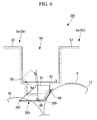
- FIG. 6 is a partial cross-sectional view for describing the structure of the support part in the printing press according to the present embodiment.
- printing units 5a, 5b of the printing press 201 each include: a drying device 51 for drying ink printed on a sheet P; and a support part 253 for supporting the drying device 51 so that it can be brought close to and away from an impression cylinder 17.
- the support part 253 serves to support the drying device 51, and to rotate around a rotation shaft 267 so as to bring the drying device 251 close to and away from the impression cylinder 17.
- the support part 253 allows the drying device 51 to be brought in close proximity to the impression cylinder 17.
- the drying device 51 when the drying device 51 is rotated upward, as indicated by the chain double-dashed line in FIG. 6 , the drying device 51 can be taken away so as to be located at a position where it can be slidingly moved in the direction of the rotation axis of the impression cylinder 17. By slidingly moving the drying device 51, the impression cylinder 17 becomes accessible from a cutout part 63.
- the support part 253 includes: a pair of rotation members 265; the rotation shaft 267 provided at one end of the rotation members 265; and two rails 69 provided across the pair of the rotation members 265.
- the rotation members 265 each consist of a rod member bent so as to be roughly L-shaped, and are located at an operating-side frame (for example, a frame located closer to the view with respect to the plane of FIG. 6 ) and at a driven-side frame (for example, a frame located further from the viewer with respect to the plane of FIG. 6 ) in the printing units 5a, 5b.
- the rotation members 265 are arranged approximately in parallel with each other, and the rotation member 265, located at the operating side in the printing press 201 (for example, one located closer to the viewer with respect to the plane of FIG. 6 ), is formed (as a lever) so that a worker can hold it.
- a worker can hold the rotation member 265 located at the operating side and can rotate it so that the support part 253 and the drying device 51 are brought close to and away from the impression cylinder 17.
- the rotation shaft 267 serves to rotatably support the rotation members 265 with respect to a frame 55, and is located close to an transfer cylinder 18.
- the rotation shaft 267 has a rotation axis extending parallel to the rotation axis of the transfer cylinder 18.
- the functions of the printing press 201 and drying device 51 according to the present variation are similar to those of the printing press and drying device according to the first embodiment, and therefore, the description thereof will be omitted.
- an inter-unit step 61 is rotated upward, exposing the drying device 51 located within the cutout part 63 to the outside, as shown in FIG. 6 . Then, the rotation member 265 is grasped and rotated in the direction in which the drying device 51 and the support part 253 are separated from the impression cylinder 17 as indicated by the chain double-dashed line in FIG. 6 .
- the drying device 51 Upon rotation of the drying device 51 to the cutout part 63, the drying device 51 is then slidingly moved along the rails 69, parallel to the rotational center axis of the transfer cylinder 18. For example, the drying device 51 is slidingly moved to the operating side of the printing units 5a, 5b (toward the viewer of FIG. 6 ).
- a space from which the impression cylinder 17 is accessible is formed between the cutout part 63 and the impression cylinder 17. A worker carries out the maintenance of the impression cylinder 17 through this space.
- the maintenance of the drying device 51 is carried out in a situation where it has been slidingly moved along the rails 69.
Landscapes
- Engineering & Computer Science (AREA)
- Mechanical Engineering (AREA)
- Supply, Installation And Extraction Of Printed Sheets Or Plates (AREA)
Abstract
A printing press capable of expediting the drying of ink printed on a sheet and facilitating maintenance is provided. The printing press is characterized by including: an impression cylinder (17) for transferring ink onto printing paper (P) during transport of the printing paper (P) therethrough; an transfer cylinder (18) for transporting the printing paper (P) on which the ink has been transferred; a drying part (51) for drying the ink transferred on the printing paper (P); and a support part (53) for supporting the drying part (51) so that it can rotate around a rotation axis extending parallel to the rotation axis of the impression cylinder (18), thereby bringing the drying part (51) close to and away from the impression cylinder (17).
Description
- The present invention relates to printing presses, and in particular to sheet-fed printing presses for printing sheets.
- Conventionally, in a sheet-fed printing press, ink printed on a printed sheet has been dried overnight. The dried sheet has been sent to a subsequent process and subjected to cutting or the like.
- However, in recent years, there has been demand to carry out cutting or the like after printing is done on a sheet, and the need for the provision of a drier for drying printed ink has been increased also in a sheet-fed printing press.
- Therefore, in order to satisfy the above-described needs, a sheet-fed printing press equipped with a drier for drying ink has been proposed (see Patent Citation 1, for example).
- Patent Citation 1: Japanese Unexamined Patent Application, Publication No.
2005-125739 - Patent Citation 1 mentioned above discloses a structure of a sheet-fed printing press including a drier having: an air guide part having a concave outline conforming to a cylinder; and a modular air blowing part.
- It is described that the above-mentioned structure is capable of drying ink, which has been printed on a paper, with the use of the drier that utilizes hot air and infrared rays in combination. Hot air blown from the air blowing part flows into the air guide part, and the hot air is guided by the air guide part so as to be immediately in front of the cylinder. It is described that the hot air, blown out from the air blowing part, can be thus blown on a printed paper placed on the cylinder.
- The above-mentioned drier is capable of slidingly moving the air blowing part in a direction of the rotation axis of the cylinder, and of rotating the air guide part around a rotation joint. It is described that, in doing so, the maintenance of the cylinder can be easily carried out.
- However, in the drier of the above-mentioned sheet-fed printing press, a gap is created between the air blowing part and the air guide part. Therefore, there was a problem that a part of the hot air, blown from the air blowing part, flowed out through the gap, and was not used for the drying of ink. Since there exists a large distance between the air blowing part and the cylinder, the temperature of the hot air, blown out from the air blowing part, was reduced when the hot air was blown on a paper placed on the cylinder, thus causing a problem that it was difficult to expedite drying.
- The air guide part was located between the air blowing part and the cylinder, thereby increasing the distance therebetween. Thus, there was a problem that the intensity of infrared rays emitted onto the cylinder from the air blowing part was reduced, thereby making it difficult to expedite the drying of ink.
- It is conceivable that this problem can be solved by a method involving locating the air blowing part closer to the cylinder and removing the air guide part.
- However, in such a structure, there is the problem that it is difficult to carry out the maintenance of the cylinder. That is, in the sheet-fed printing press, various mechanisms are located beside the cylinder. Therefore, a air blowing part which is located closer to the cylinder interferes with those mechanisms, thus making it impossible to slidingly move the air blowing part in the direction of the rotation axis of the cylinder. As a result, the cylinder is always covered by the air blowing part, thus causing a problem that it is difficult to carry out the maintenance of the cylinder. Since it is impossible to take out the air blowing part, there is the problem that it is also difficult to carry out the maintenance of the air blowing part.
- The present invention has been made in view of the above-described problems, and its object is to provide a printing press capable of expediting the drying of ink printed on a sheet, and facilitating maintenance.
- To achieve the above object, the present invention provides the following means.
- The present invention provides a printing press including: an impression cylinder for allowing ink to be transferred on a printing paper during transport of the printing paper therethrough; an transfer cylinder for transporting the printing paper on which the ink has been transferred; a drying part for drying the ink transferred on the printing paper; and a support part for supporting the drying part so that it is rotatable around a rotation axis extending parallel to the rotation axis of the impression cylinder, thereby bringing the drying part close to and away from the impression cylinder.
- According to the present invention, there is provided the support part for supporting the drying part so that it can be brought close to and away from the impression cylinder; thus, the drying of ink printed on the printing paper can be expedited, and in addition, the maintenance of the impression cylinder and the drying part can be facilitated.
- The support part supports the drying part so that it is rotatable around the rotation axis extending parallel to the rotation axis of the impression cylinder; thus, when the drying part is brought to the impression cylinder, the drying part can be in close proximity to the impression cylinder. Therefore, the drying part can be brought in close proximity to the printing paper on which ink has been transferred, and the drying of the ink can be expedited.
- On the other hand, when the drying part is removed from the impression cylinder, the drying part can be at a position far from the impression cylinder; therefore, for example, at such a position far from the impression cylinder, the drying part can be slidingly moved in the direction of the rotation axis of the impression cylinder. Thus, the maintenance of the drying part can be easily carried out. By slidingly moving the drying part, a space which communicates with the outside can be formed between the impression cylinder and the drying part, and the access to the impression cylinder can be facilitated.
- The drying part is moved in a plane approximately perpendicular to the rotation axis of the impression cylinder; therefore, for example, even if various mechanisms are located beside the impression cylinder and/or the transfer cylinder, the drying part can be moved, and the maintenance of the drying part can be facilitated.
- In the foregoing invention, there is preferably provided a pushing-up part for pushing up the support part in a direction in which it is taken away from the impression cylinder or the transfer cylinder.
- By providing the pushing-up part in this way, the maintenance of the impression cylinder and the drying part can be facilitated.
- The pushing-up part pushes up the support part in the direction in which it is taken away from the impression cylinder, thereby pushing up the drying part, supported by the support part, in the direction in which the drying part is taken away from the impression cylinder. For example, when a worker caries out the maintenance of the impression cylinder or the drying part, the support part and the drying part can be taken away from the impression cylinder by means of the pushing-up force of the pushing-up part. Thus, there is no need to use the force of a worker in taking the support part and the drying part away from the impression cylinder, and the maintenance of the impression cylinder or the drying part can be facilitated.
- In the foregoing invention, the drying part is preferably supported on the support part so as to be rotatable in a direction in which the drying part is taken away from the impression cylinder.
- In such an aspect, since the drying part on the support part is rotated in the direction in which it is taken away from the impression cylinder, the maintenance of the impression cylinder can be facilitated.
- By rotating the drying part on the support part in the direction in which it is taken away from the impression cylinder, the drying part located close to the impression cylinder can be taken away from the impression cylinder, thereby forming a space communicating with the outside. The impression cylinder becomes accessible from the outside through this space, and the maintenance of the impression cylinder can be facilitated.
- Since it is possible to carry out the maintenance of the impression cylinder without rotating its support part, the maintenance of the impression cylinder can be made easier than a method involving rotating its support part.
- In the foregoing invention, the support part is preferably equipped with a movement support part which supports the drying part so that it is movable in the direction of the rotation axis of the impression cylinder.
- Since the support part is equipped with a movement support part which supports the drying part so that it is movable in the direction of the rotation axis of the impression cylinder in this way, the maintenance of the drying part can be facilitated.
- The drying part is moved in the direction of the rotation axis of the impression cylinder by means of the movement support part; therefore, the drying part can be taken further away from the impression cylinder, thereby making it possible to form a larger space communicating with the outside. Thus, when the maintenance of the impression cylinder is carried out, the drying part will not be an obstacle, and the maintenance can be further facilitated.
- Since the drying part is moved in the direction of the rotation axis of the impression cylinder by means of the movement support part, the drying part can be moved to a larger space. Thus, the maintenance of the drying part can be further facilitated.
- The printing press of the present invention includes the support part for supporting the drying part so that it can be brought close to and away from the impression cylinder, thus achieving the effects of allowing the drying of ink which is printed on printing paper to be expedited, and allowing the maintenance of the impression cylinder and the drying part to be facilitated.
-
- [
FIG. 1 ] A cross-sectional view for describing a structure of a sheet-fed printing press according to a first embodiment of the present invention. - [
FIG. 2 ] A partial cross-sectional view for describing a structure of a printing unit shown inFIG. 1 . - [
FIG. 3 ] A partial cross-sectional view for describing a situation in which a printing device and a support part shown inFIG. 2 are taken away from an impression cylinder. - [
FIG. 4 ] A diagram for describing another embodiment of the printing press shown inFIG. 1 . - [
FIG. 5 ] A partial cross-sectional view for describing a structure of a support part in a printing press according to a variation of the first embodiment of the present invention. - [
FIG. 6 ] A partial cross-sectional view for describing a structure of a support part in a printing press according to a second embodiment of the present invention. -
- 1, 101, 201: printing press
- 17: impression cylinder
- 18: transfer cylinder
- 51: drying device (drying part)
- 53, 153, 253: support part
- 69: rail (movement support part)
- 71: spring part (pushing-up part)
- P: sheet (printing paper)
- Hereinafter, a sheet-fed printing press according to a first embodiment of the present invention will be described with reference to
FIGS. 1 to 4 . -
FIG. 1 is a cross-sectional view for describing a structure of a sheet-fed printing press according to the present embodiment. - The sheet-fed printing press (hereinafter, simply called a "printing press") 1 in the present embodiment is a double-sided printing press for printing the front side and back side of a sheet (printing paper) P serving as a substrate. From the upstream side, from which the sheets P serving as substrates are fed, toward the downstream side, the printing press 1 includes: a feeder 3; a plurality of
printing units 5a for printing the front side of each sheet; an invertingunit 21 for inverting each sheet; a plurality ofprinting units 5b for printing the back side of each sheet; and a paper ejecting device 7. - The feeder 3 serves as a device for feeding, one by one, stacked sheet substrates.
- The paper ejecting device 7 serves as a device for collecting and stacking printed substrates. The paper ejecting device 7 is provided with an imaging device (not shown) for grasping how the substrate is printed.
- The paper ejecting device 7 is provided with an ejected paper identification device (not shown) for making markings or the like on the printed sheets P. As the delivery identification device, for example, a tape inserter for putting tags on predetermined sheets P, and/or double delivery or the like for separating a predetermined number of sheets P into a different stack from the other sheets is used.
- As shown in
FIG. 1 , a plurality of theprinting units printing units 5a, and then the back side of each sheet P is printed using the fourprinting units 5b. - The
printing units ink device 9 for supplying ink; aplate cylinder 13 located facing theink device 9; ablanket cylinder 15 located facing theplate cylinder 13; animpression cylinder 17 located facing theblanket cylinder 15; and antransfer cylinder 18 located between theimpression cylinders 17 of therespective printing units - As shown in
FIG. 1 , theprinting units ink device 9 for supplying ink; a dampening device 11 for supplying dampening solution; theplate cylinder 13 located facing theseink devices 9 and dampening device 11; theblanket cylinder 15 located facing theplate cylinder 13; theimpression cylinder 17 located facing theblanket cylinder 15; and thetransfer cylinder 18 located between theimpression cylinders 17 of therespective printing units - Each
ink device 9 includes a plurality of ink rollers, and is formed so as to sequentially supply ink from an ink reservoir, in which ink is stored, toward theplate cylinder 13. Eachink device 9 includes four ink-applying rollers that come into contact with theplate cylinder 13 during printing. - Each dampening device 11 includes a plurality of rollers, and is formed so as to supply dampening solution, stored in a solution vessel, toward the
plate cylinder 13. Each dampening device 11 includes a single dampening roller that comes into contact with the plate cylinder during printing. - Each
plate cylinder 13 is formed into a cylindrical shape, around the periphery of which a printing plate, having a printing image formed thereon, is wound. The printing plate is formed and changed for each image to be printed. Eachplate cylinder 13 is in a state where a part of its periphery covering a certain angle is cut out in the axial direction, and the resulting gap is provided with plate clamping devices (not shown) for holding and fixing a plate head and a plate bottom which are upstream and downstream, respectively, of the printing plate. - A blanket made of rubber or the like is wound around the periphery of each
blanket cylinder 15. Eachblanket cylinder 15 is in a state where a part of its periphery covering a certain angle is cut out in the axial direction, and the resulting gap is provided with a rubber clamping device (not shown) for holding and fixing the upstream end and the downstream end of the rubber. - Each
blanket cylinder 15 is formed so that it can be taken away from the plate cylinder 13 (i.e., the cylinders can be disconnected) in a non-printing period during which printing is not performed. - Each
impression cylinder 17 is located facing theblanket cylinder 15, and is formed into a cylindrical shape. During printing, eachimpression cylinder 17 comes into contact with theblanket cylinder 15, and presses the substrate supplied between theimpression cylinder 17 and theblanket cylinder 15 with a desired pressure. - Each
transfer cylinder 18 is provided between theimpression cylinders 17 of therespective printing units 5, and is formed into a cylindrical shape. Eachtransfer cylinder 18 sends the sheets P, serving as substrates, from upstream ofimpression cylinder 17 to downstream ofimpression cylinder 17. - The above-described
plate cylinders 13,blanket cylinders 15,impression cylinders 17, and transfercylinders 18 are rotated by a single main motor (not shown) provided in the printing press 1. In other words, a torque from the main motor is transmitted to theimpression cylinders 17,transfer cylinders 18,blanket cylinders 15 and theplate cylinders 13 via gears. -
FIG. 2 is a partial cross-sectional view for describing a structure of each printing unit shown inFIG. 1 . - As shown in
FIG. 2 , theprinting units support part 53 for supporting the dryingdevice 51 so that it can be brought close to and away from theimpression cylinder 17. - As shown in
FIG. 1 , frames 55 serving as casings for theprinting units convex part 57 in which theink device 9, the dampening device 11 and the like are located. As shown inFIG. 2 , aspace 59 through which a worker can pass is formed between theconvex parts adjacent printing units convex parts adjacent printing units frame 55 located at a bottom face of thespace 59, aninter-unit step 61 serving as a footboard for a worker is located, and aconcave cutout part 63 is formed under the inter-unit step 61 (at a lower part ofFIG. 2 ). In other words, theinter-unit step 61 is located so as to cover thecutout part 63. - The
cutout part 63 may be provided with wiring through which electric power is supplied to the dryingdevice 51, or may be used as a ventilation duct. - The
inter-unit step 61 is fixed so as to be rotatable toward the downstreamside printing unit 5a orprinting unit 5b with respect to the direction in which the sheet P flows. - The drying
device 51 serves to dry ink printed on the sheet P, and is a UV irradiation type drying device for irradiating ultraviolet rays (hereinafter, expressed as UV), for example. It should be noted that the dryingdevice 51 is not particularly limited, the above-mentioned UV irradiation type drying device, a drying device for irradiating infrared rays, or a drying device for blowing hot air being usable in accordance with the drying properties of ink. -
FIG. 3 is a partial cross-sectional view for describing a situation in which thedrying device 51 and thesupport part 53 inFIG. 2 are separated from theimpression cylinder 17. - The
support part 53 serves to support the dryingdevice 51, and to rotate around arotation shaft 67 so as to bring thedrying device 51 close to and away from theimpression cylinder 17. - Specifically, as shown in
FIG. 2 , when thesupport part 53 rotates the dryingdevice 51 downward, this allows the dryingdevice 51 to be brought in close proximity to theimpression cylinder 17. - On the other hand, as shown in
FIG. 3 , when the dryingdevice 51 is rotated upward, the dryingdevice 51 can be taken away so as to be located at a position where it can be slidingly moved in the direction of the rotation axis of theimpression cylinder 17. By slidingly moving the dryingdevice 51, theimpression cylinder 17 becomes accessible from thespace 59. - As shown in
FIG. 2 , thesupport part 53 includes: a pair ofrotation members 65; therotation shaft 67 provided at one end of therotation members 65; two rails (movement support part) 69 provided extending across a pair of therotation members 65; and a spring part (pushing-up part) 71 for urging thesupport part 53 in the direction in which it separates from theimpression cylinder 17. - The
rotation members 65 each consist of a rod member bent so as to be roughly L-shaped, and are located at an operating frame (for example, a frame located closer to the viewer with respect to the plane ofFIG. 2 ) and at a power drive frame (for example, a frame located away from the viewer with respect to the plane ofFIG. 2 ) in theprinting units rotation members 65 are arranged approximately in parallel with each other, and therotation member 65 located at the operating side of the printing press 1 (for example, one located closer to the viewer with respect to the plane ofFIG. 2 ), is formed (as a lever) so that a worker can hold it. A worker can hold therotation member 65, located at the operating side, and can rotate it so that thesupport part 53 and the dryingdevice 51 are brought close to and away from theimpression cylinder 17. - The
rotation shaft 67 serves to rotatably support therotation members 65 with respect to theframes 55, and is located above theimpression cylinder 17 and close to the bottom face of thespace 59. Therotation shaft 67 has a rotation axis extending parallel to the rotation axis of theimpression cylinder 17. - The
rails 69 serve to support the dryingdevice 51 so that it is movable in the direction of the rotation axis of theimpression cylinder 17. The tworails 69 are arranged side by side so as to extend in the direction of the rotation axis of theimpression cylinder 17, and are located so as to connect with a pair of therotation members 65. - The
spring part 71 is a member that is fixed, at one end thereof, to therotation members 65, and is fixed, at the other end thereof, to theframe 55. Thespring part 71 is compressed in a state where the dryingdevice 51 is located close to theimpression cylinder 17, and urges the dryingdevice 51 and thesupport part 53 in the direction in which they separate from theimpression cylinder 17. It should be noted that thespring part 71 may be a known spring such as a coil spring. The means for urging thesupport part 53 as described above is not particularly limited since thespring part 71 may be used, or other urging means may be used. - Next, the functions of the printing press 1 structured as described above will be described.
- First, as shown in
FIG. 1 , the sheets P are sent out one by one from the feeder 3. The sheet P has its front side printed when passing through the first fourprinting units 5a. Thereafter, the sheet P is inverted by the invertingunit 21. - The sheet P which has been inverted has its back side printed when passing through the four
printing units 5b located at the downstream side. The sheet P, which has its both sides printed in this manner, is sent to the paper ejecting device 7. - Next, the functions of the drying device, which are features of the present embodiment, will be described.
- The sheet, on which predetermined ink has been printed in the
printing units transfer cylinder 18 by theimpression cylinder 17 as shown inFIG. 2 . A region of the sheet on which ink has been printed facing the dryingdevice 51 is irradiated with ultraviolet rays emitted from the dryingdevice 51, thereby drying the ink on the sheet. The sheet, the ink of which has been dried, is transported from theimpression cylinder 17 to thetransfer cylinder 18, and is then transported from thetransfer cylinder 18 to theimpression cylinder 17 of thenext printing units - By repeating the above-described steps, both the printing and drying steps are carried out in each of the
printing units - Next, a maintenance method for the
impression cylinder 17 or the dryingdevice 51, which is a feature of the present embodiment, will be described. - When the maintenance of the
impression cylinder 17 or the dryingdevice 51 is to be carried out, first, theinter-unit step 61 is rotated upward, exposing the dryingdevice 51 located within thecutout part 63 to the outside, as shown inFIG. 3 . Then, therotation member 65 is grasped and rotated in the direction in which thedrying device 51 and thesupport part 53 are separated from theimpression cylinder 17. At this time, since the urging force of thespring part 71 is exerted, the force for rotating the dryingdevice 51 and thesupport part 53 is small. Alternatively, the dryingdevice 51 and thesupport part 53 are rotated in the direction in which they separate from theimpression cylinder 17 by the urging force of thespring part 71 alone. - Upon rotation of the drying
device 51 to thecutout part 63, the dryingdevice 51 is then slidingly moved along therails 69, parallel to the rotational center axis of theimpression cylinder 17. For example, the dryingdevice 51 is slidingly moved to the operating side of theprinting units FIG. 3 ). - Upon movement of the drying
device 51, there occurs a situation in which only thesupport part 53 is located between thespace 59 and theimpression cylinder 17. Since thesupport part 53 is constituted by a combination of therotation members 65 and therails 69, a space from which theimpression cylinder 17 is accessible is formed between thespace 59 and theimpression cylinder 17. A worker carries out the maintenance of theimpression cylinder 17 through this space. - On the other hand, the maintenance of the drying
device 51 is carried out in a situation where it has been slidingly moved along therails 69. - In the above-described structure, there is provided the
support part 53 for supporting the dryingdevice 51 so that it can be brought close to and away from theimpression cylinder 17, thus making it possible to expedite the drying of ink printed on sheets, and to facilitate the maintenance of theimpression cylinder 17 and the dryingdevice 51. - The
support part 53 supports the dryingdevice 51 so that it is rotatable around the rotation axis extending parallel to the rotation axis of theimpression cylinder 17; therefore, when the dryingdevice 51 is brought to theimpression cylinder 17, the dryingdevice 51 can be in close proximity to theimpression cylinder 17. Thus, the dryingdevice 51 can be brought in close proximity to the sheet on which ink has been transferred, and the drying of the ink can be facilitated. - On the other hand, when the drying
device 51 is taken away from theimpression cylinder 17, the dryingdevice 51 can be moved to a position far from theimpression cylinder 17; therefore, for example, at a position far from theimpression cylinder 17, the dryingdevice 51 can be slidingly moved in the direction of the rotation axis of theimpression cylinder 17. Thus, the maintenance of the dryingdevice 51 can be easily carried out. By slidingly moving the dryingdevice 51, a space communicating with the outside can be formed between theimpression cylinder 17 and the dryingdevice 51, and the access to theimpression cylinder 17 can be facilitated. - The drying
device 51 is moved in a plane approximately perpendicular to the rotation axis of theimpression cylinder 17; therefore, for example, even if various mechanisms are located beside theimpression cylinder 17 and/or thetransfer cylinder 18, the dryingdevice 51 can be slidingly moved, and the maintenance of the dryingdevice 51 can be facilitated. - By providing the
spring part 71, the maintenance of theimpression cylinder 17 and the dryingdevice 51 can be facilitated. - The
spring part 71 pushes up thesupport part 53 in the direction in which it separates from theimpression cylinder 17, thereby pushing up the dryingdevice 51 supported by thesupport part 53 in the direction in which thedrying device 51 separates from theimpression cylinder 17. For example, when a worker carries out the maintenance of theimpression cylinder 17 or the dryingdevice 51, thesupport part 53 and the dryingdevice 51 can be removed from theimpression cylinder 17 by means of the pushing-up force of thespring part 71. Thus, there is no need to use the force of a worker in taking thesupport part 53 and the dryingdevice 51 away from theimpression cylinder 17, and the maintenance of theimpression cylinder 17 or the dryingdevice 51 can be facilitated. - Since the
support part 53 includes therails 69 that support the dryingdevice 51 so that it is slidingly movable in the direction of the rotation axis of theimpression cylinder 17, the maintenance of the dryingdevice 51 can be facilitated. - By means of the
rails 69, the dryingdevice 51 is moved in the direction of the rotation axis of theimpression cylinder 17; therefore, the dryingdevice 51 can be taken further away from theimpression cylinder 17, thereby making it possible to form a larger space communicating with the outside. Thus, when the maintenance of theimpression cylinder 17 is carried out, the dryingdevice 51 will not be an obstacle, and the maintenance can be further facilitated. - Since the drying
device 51 can be moved in the direction of the rotation axis of theimpression cylinder 17 by means of therails 69, the dryingdevice 51 can be moved to a larger space. Thus, the maintenance of the dryingdevice 51 can be further facilitated. - Since the
printing units device 51, a drying unit for drying ink does not have to be located upstream of the invertingunit 21 in the printing press 1. At the same time, a paper ejecting device 7 such as a long delivery apparatus including a plurality of drying devices for drying ink does not have to be used. -
FIG. 4 is a diagram for describing another embodiment of the printing press shown inFIG. 1 . - It should be noted that the printing press 1 is not particularly limited to a double-sided sheet-fed printing press capable of printing the front side and back side of each sheet as described above, and may be a sheet-fed printing press capable of printing only the front side of each sheet as shown in
FIG. 4 . - Next, a variation of the embodiment of the present invention will be described with reference to
FIG. 5 . - A basic structure of a printing press according to the present variation is similar to that of the printing press according to the first embodiment, but the structure of a support part differs from the first embodiment. Hence, in the present embodiment, only the surroundings of the support part will be described with reference to
FIG. 5 , and the description of the other constituent elements and the like will be omitted. -
FIG. 5 is a partial cross-sectional view for describing the structure of the support part in the printing press according to the present variation. - It should be noted that the same constituent elements as those of the first embodiment are identified by the same reference characters, and the description thereof will be omitted.
- As shown in
FIG. 5 ,printing units printing press 101 each include: a dryingdevice 51 for drying ink printed on a sheet P; and asupport part 153 for supporting the dryingdevice 51 so that it can be brought close to and away from animpression cylinder 17. - As shown in
FIG. 2 , thesupport part 153 serves to support the dryingdevice 51, and to rotate around arotation shaft 67 so as to bring thedrying device 51 close to and away from theimpression cylinder 17. - The
support part 153 includes: a pair ofrotation members 65; therotation shaft 67 provided at one end of therotation members 65; aspring part 71 for urging thesupport part 53 in a direction in which it separates from theimpression cylinder 17; arotation support part 155 for rotatably supporting the dryingdevice 51 on therotation members 65; and astopper 157 for regulating the rotation of the dryingdevice 51 around therotation support part 155. - The
rotation support part 155 is located at one end of the rotation members 65 (at the left side end inFIG. 5 ), and connects therotation members 65 with the dryingdevice 51 so that the dryingdevice 51 can rotate around one end of therotation members 65. - The
stopper 157 is provided at therotation members 65, and serves to regulate the rotation range of the dryingdevice 51 when the dryingdevice 51 is rotated toward theimpression cylinder 17. Specifically, the stopper serves to regulate the position of the dryingdevice 51 so that the surface of the dryingdevice 51 providing UV irradiation faces theimpression cylinder 17. - Next, the functions of the
printing press 101 structured as described above, and the functions of the dryingdevice 51 will be described. - The functions of the
printing press 101 and dryingdevice 51 according to the present variation are similar to those of the printing press and drying device according to the first embodiment, and therefore, the description thereof will be omitted. - Next, a maintenance method for the
impression cylinder 17 or the dryingdevice 51, which is a feature of the present variation, will be described. - When the maintenance of the
impression cylinder 17 is carried out in theprinting press 101 according to the present variation, similarly to the first embodiment, aninter-unit step 61 is rotated upward, exposing the dryingdevice 51 located within acutout part 63 to the outside. Then, the dryingdevice 51 is rotated by means of therotation support part 155 as indicated by the chain double-dashed line inFIG. 5 . - Upon rotation of the drying
device 51, a space from which theimpression cylinder 17 is accessible is formed between thecutout part 63 and theimpression cylinder 17. A worker carries out the maintenance of theimpression cylinder 17 through this space. - It should be noted that the method of carrying out the maintenance of the
impression cylinder 17 and the dryingdevice 51 by rotating theentire support part 153 in the direction in which it separated from theimpression cylinder 17 is similar to that of the first embodiment, and therefore, the description thereof will be omitted. - In the above-described structure, the drying
device 51 is rotated above thesupport part 153 in the direction in which it is separated from theimpression cylinder 17, and therefore, the maintenance of theimpression cylinder 17 can be facilitated. - By connecting the drying
device 51 with therotation members 65 using therotation support part 155, the dryingdevice 51 can be rotated in the direction in which it is separated from theimpression cylinder 17 over thesupport part 153. - By rotating the drying
device 51 in the direction in which it is separated from theimpression cylinder 17, the dryingdevice 51 located close to theimpression cylinder 17 can be taken away from theimpression cylinder 17, thereby making it possible to form a space communicated with the outside. Theimpression cylinder 17 becomes accessible from the outside through this space, and the maintenance of theimpression cylinder 17 can be facilitated. - Since it is possible to carry out the maintenance of the
impression cylinder 17 without rotating theentire support part 153, the maintenance of theimpression cylinder 17 can be facilitated as compared with a method of rotating theentire support part 153. - Next, a second embodiment of the present invention will be described with reference to
FIG. 6 . - The basic structure of a printing press according to the present embodiment is similar to that of the printing press according to the first embodiment, but the structure of a support part differs from the first embodiment. Hence, in the present embodiment, only the surroundings of the support part will be described with reference to
FIG. 6 , and the description of the other constituent elements and the like will be omitted. -
FIG. 6 is a partial cross-sectional view for describing the structure of the support part in the printing press according to the present embodiment. - It should be noted that the same constituent elements as those of the first embodiment are identified by the same reference characters, and the description thereof will be omitted.
- As shown in
FIG. 6 ,printing units printing press 201 each include: a dryingdevice 51 for drying ink printed on a sheet P; and asupport part 253 for supporting the dryingdevice 51 so that it can be brought close to and away from animpression cylinder 17. - The
support part 253 serves to support the dryingdevice 51, and to rotate around arotation shaft 267 so as to bring the drying device 251 close to and away from theimpression cylinder 17. - Specifically, as indicated by the solid line in
FIG. 6 , when the dryingdevice 51 is rotated downward, thesupport part 253 allows the dryingdevice 51 to be brought in close proximity to theimpression cylinder 17. - On the other hand, when the drying
device 51 is rotated upward, as indicated by the chain double-dashed line inFIG. 6 , the dryingdevice 51 can be taken away so as to be located at a position where it can be slidingly moved in the direction of the rotation axis of theimpression cylinder 17. By slidingly moving the dryingdevice 51, theimpression cylinder 17 becomes accessible from acutout part 63. - As shown in
FIG. 6 , thesupport part 253 includes: a pair ofrotation members 265; therotation shaft 267 provided at one end of therotation members 265; and tworails 69 provided across the pair of therotation members 265. - The
rotation members 265 each consist of a rod member bent so as to be roughly L-shaped, and are located at an operating-side frame (for example, a frame located closer to the view with respect to the plane ofFIG. 6 ) and at a driven-side frame (for example, a frame located further from the viewer with respect to the plane ofFIG. 6 ) in theprinting units rotation members 265 are arranged approximately in parallel with each other, and therotation member 265, located at the operating side in the printing press 201 (for example, one located closer to the viewer with respect to the plane ofFIG. 6 ), is formed (as a lever) so that a worker can hold it. A worker can hold therotation member 265 located at the operating side and can rotate it so that thesupport part 253 and the dryingdevice 51 are brought close to and away from theimpression cylinder 17. - The
rotation shaft 267 serves to rotatably support therotation members 265 with respect to aframe 55, and is located close to antransfer cylinder 18. Therotation shaft 267 has a rotation axis extending parallel to the rotation axis of thetransfer cylinder 18. - Next, the functions of the
printing press 201 structured as described above, and the functions of the dryingdevice 51 will be described. - The functions of the
printing press 201 and dryingdevice 51 according to the present variation are similar to those of the printing press and drying device according to the first embodiment, and therefore, the description thereof will be omitted. - Next, a maintenance method for the
impression cylinder 17 or the dryingdevice 51, which is a feature of the present embodiment, will be described. - When the maintenance of the
impression cylinder 17 or the dryingdevice 51 is carried out, first, aninter-unit step 61 is rotated upward, exposing the dryingdevice 51 located within thecutout part 63 to the outside, as shown inFIG. 6 . Then, therotation member 265 is grasped and rotated in the direction in which thedrying device 51 and thesupport part 253 are separated from theimpression cylinder 17 as indicated by the chain double-dashed line inFIG. 6 . - Upon rotation of the drying
device 51 to thecutout part 63, the dryingdevice 51 is then slidingly moved along therails 69, parallel to the rotational center axis of thetransfer cylinder 18. For example, the dryingdevice 51 is slidingly moved to the operating side of theprinting units FIG. 6 ). - Upon movement of the drying
device 51, a space from which theimpression cylinder 17 is accessible is formed between thecutout part 63 and theimpression cylinder 17. A worker carries out the maintenance of theimpression cylinder 17 through this space. - On the other hand, the maintenance of the drying
device 51 is carried out in a situation where it has been slidingly moved along therails 69.
Claims (4)
- A printing press comprising:an impression cylinder for transferring ink onto printing paper during transport of the printing paper therethrough;an transfer cylinder for transporting the printing paper on which the ink has been transferred;a drying part for drying the ink transferred on the printing paper; anda support part for supporting the drying part so that it is rotatable around a rotation axis extending parallel to the rotation axis of the impression cylinder, thereby bringing the drying part close to and away from the impression cylinder.
- The printing press according to claim 1, comprising a pushing-up part for pushing up the support part in a direction in which it is separated from the impression cylinder or the transfer cylinder.
- The printing press according to claim 1 or 2, wherein the drying part is supported so as to be rotatable in a direction in which the drying part is separated from the impression cylinder over the support part.
- The printing press according to any one of claims 1 to 3, wherein the support part comprises a movement support part for supporting the drying device so that it is movable in the direction of the rotation axis of the impression cylinder.
Applications Claiming Priority (2)
| Application Number | Priority Date | Filing Date | Title |
|---|---|---|---|
| JP2006043806A JP2007223066A (en) | 2006-02-21 | 2006-02-21 | Printing machine |
| PCT/JP2007/052870 WO2007097263A1 (en) | 2006-02-21 | 2007-02-16 | Printer |
Publications (1)
| Publication Number | Publication Date |
|---|---|
| EP1987952A1 true EP1987952A1 (en) | 2008-11-05 |
Family
ID=38437303
Family Applications (1)
| Application Number | Title | Priority Date | Filing Date |
|---|---|---|---|
| EP07714400A Withdrawn EP1987952A1 (en) | 2006-02-21 | 2007-02-16 | Printer |
Country Status (5)
| Country | Link |
|---|---|
| US (1) | US20090050008A1 (en) |
| EP (1) | EP1987952A1 (en) |
| JP (1) | JP2007223066A (en) |
| CN (1) | CN101360611A (en) |
| WO (1) | WO2007097263A1 (en) |
Cited By (2)
| Publication number | Priority date | Publication date | Assignee | Title |
|---|---|---|---|---|
| WO2016050862A1 (en) * | 2014-09-30 | 2016-04-07 | manroland sheetfed GmbH | Sheet-fed rotary offset printing press having devices for the homogeneous drying of printed sheets which are printed on both sides |
| EP4059717A1 (en) * | 2021-03-18 | 2022-09-21 | Heidelberger Druckmaschinen AG | Hot air dryer in a printing press |
Families Citing this family (5)
| Publication number | Priority date | Publication date | Assignee | Title |
|---|---|---|---|---|
| KR101040669B1 (en) * | 2008-10-15 | 2011-06-10 | 주식회사 디지아이 | Heating device of digital printing machine |
| JP5517474B2 (en) * | 2009-02-25 | 2014-06-11 | 三菱重工印刷紙工機械株式会社 | Printing apparatus, printing method, sheet-fed printing press and rotary printing press |
| JP5695899B2 (en) * | 2010-12-28 | 2015-04-08 | リョービMhiグラフィックテクノロジー株式会社 | Printer |
| JP5931565B2 (en) * | 2012-04-25 | 2016-06-08 | リョービMhiグラフィックテクノロジー株式会社 | Printer |
| EP3015266A1 (en) * | 2014-10-30 | 2016-05-04 | KBA-NotaSys SA | Printing press comprising a magnetic orientation unit and a movable drying/curing unit |
Family Cites Families (9)
| Publication number | Priority date | Publication date | Assignee | Title |
|---|---|---|---|---|
| US3052991A (en) * | 1959-02-24 | 1962-09-11 | Midland Ross Corp | Apparatus for uniform accelerated drying of web material |
| EP0044369B1 (en) * | 1980-07-18 | 1987-11-11 | Jean Lucien Sarda | Thermal engraving machine for relief printing |
| US4340893A (en) * | 1980-11-05 | 1982-07-20 | Xerox Corporation | Scanning dryer for ink jet printers |
| DE9405223U1 (en) * | 1994-03-28 | 1994-06-09 | Man Roland Druckmaschinen Ag, 63069 Offenbach | Dryer device for a sheet-fed rotary printing machine |
| JP2002248733A (en) * | 2001-02-23 | 2002-09-03 | Japan Storage Battery Co Ltd | UV irradiation device |
| JP4041744B2 (en) * | 2003-01-15 | 2008-01-30 | リョービ株式会社 | Printing machine with plate temperature controller |
| JP2005125739A (en) * | 2003-10-27 | 2005-05-19 | Heidelberger Druckmas Ag | Sheet-feed press with drier |
| JP2007007936A (en) * | 2005-06-29 | 2007-01-18 | Mitsubishi Heavy Ind Ltd | Drying device of sheet-fed press |
| JP4658723B2 (en) * | 2005-07-14 | 2011-03-23 | 株式会社小森コーポレーション | Printing machine or coating machine |
-
2006
- 2006-02-21 JP JP2006043806A patent/JP2007223066A/en not_active Withdrawn
-
2007
- 2007-02-16 EP EP07714400A patent/EP1987952A1/en not_active Withdrawn
- 2007-02-16 WO PCT/JP2007/052870 patent/WO2007097263A1/en not_active Ceased
- 2007-02-16 CN CNA2007800016972A patent/CN101360611A/en active Pending
- 2007-02-16 US US12/279,147 patent/US20090050008A1/en not_active Abandoned
Non-Patent Citations (1)
| Title |
|---|
| See references of WO2007097263A1 * |
Cited By (2)
| Publication number | Priority date | Publication date | Assignee | Title |
|---|---|---|---|---|
| WO2016050862A1 (en) * | 2014-09-30 | 2016-04-07 | manroland sheetfed GmbH | Sheet-fed rotary offset printing press having devices for the homogeneous drying of printed sheets which are printed on both sides |
| EP4059717A1 (en) * | 2021-03-18 | 2022-09-21 | Heidelberger Druckmaschinen AG | Hot air dryer in a printing press |
Also Published As
| Publication number | Publication date |
|---|---|
| WO2007097263A1 (en) | 2007-08-30 |
| JP2007223066A (en) | 2007-09-06 |
| CN101360611A (en) | 2009-02-04 |
| US20090050008A1 (en) | 2009-02-26 |
Similar Documents
| Publication | Publication Date | Title |
|---|---|---|
| JP7258730B2 (en) | Mechanical structure and method for continuously processing sheet-shaped base material | |
| US8870361B2 (en) | Printing device, printing method, sheet-fed printing press, and rotary printing press | |
| US20090050008A1 (en) | Printing press | |
| US8505450B2 (en) | Printing unit, printing press and method of producing labels or self-adhesive labels in a printing press | |
| CN101180186B (en) | Single-pass double-sided image transfer process and system | |
| CN106794693B (en) | Combined printing press | |
| US6477950B1 (en) | Apparatus and method for duplex printing of a sheet-like substrate | |
| CN109153272B (en) | Sheetfed Press | |
| US20080022875A1 (en) | Sheet-fed printing press | |
| JP2010094953A (en) | Printer and paper sheet printer | |
| JPH0775885B2 (en) | Device for replacing plate | |
| WO2011013442A1 (en) | Printing machine | |
| US5558021A (en) | Printing device for printing plastic cards | |
| US20070289461A1 (en) | Printing Machine Having at Least One Printing Unit for Imprinting a Web of Material to Be Imprinted by Offset Printing in a Variable Cut Length and a Folder | |
| DE102015223110A1 (en) | Apparatus and method for treating substrates | |
| JP4851419B2 (en) | Apparatus and method for finishing a sheet-like substrate in a sheet printer | |
| DE102015223104A1 (en) | Apparatus for treating substrates | |
| JP2009096201A (en) | Printing plate exchanging method and exchanging device in processing machine | |
| CN118139745A (en) | Device for providing sheet-like substrate sections, and machine and method for handling and/or processing web-like substrates | |
| JP2010149412A (en) | Printing apparatus, printing method, sheet-fed printer, and rotary printing machine | |
| DE102015223095A1 (en) | Apparatus for treating substrates | |
| JP2013241002A (en) | Sheet digital printing apparatus | |
| JP2009072932A (en) | Guide mechanism in surface treatment device of printing machine | |
| JP2008162283A (en) | Sheet-fed printing press equipped with foil transfer unit | |
| JP5468929B2 (en) | Printer |
Legal Events
| Date | Code | Title | Description |
|---|---|---|---|
| PUAI | Public reference made under article 153(3) epc to a published international application that has entered the european phase |
Free format text: ORIGINAL CODE: 0009012 |
|
| 17P | Request for examination filed |
Effective date: 20080818 |
|
| AK | Designated contracting states |
Kind code of ref document: A1 Designated state(s): DE |
|
| RBV | Designated contracting states (corrected) |
Designated state(s): DE |
|
| STAA | Information on the status of an ep patent application or granted ep patent |
Free format text: STATUS: THE APPLICATION HAS BEEN WITHDRAWN |
|
| 18W | Application withdrawn |
Effective date: 20091020 |