EP1987790B1 - Dismountable medical pincer system - Google Patents
Dismountable medical pincer system Download PDFInfo
- Publication number
- EP1987790B1 EP1987790B1 EP08008152.4A EP08008152A EP1987790B1 EP 1987790 B1 EP1987790 B1 EP 1987790B1 EP 08008152 A EP08008152 A EP 08008152A EP 1987790 B1 EP1987790 B1 EP 1987790B1
- Authority
- EP
- European Patent Office
- Prior art keywords
- force
- seat
- connection element
- transmission element
- handle
- Prior art date
- Legal status (The legal status is an assumption and is not a legal conclusion. Google has not performed a legal analysis and makes no representation as to the accuracy of the status listed.)
- Active
Links
Images


Classifications
-
- A—HUMAN NECESSITIES
- A61—MEDICAL OR VETERINARY SCIENCE; HYGIENE
- A61B—DIAGNOSIS; SURGERY; IDENTIFICATION
- A61B17/00—Surgical instruments, devices or methods, e.g. tourniquets
- A61B17/16—Bone cutting, breaking or removal means other than saws, e.g. Osteoclasts; Drills or chisels for bones; Trepans
- A61B17/1604—Chisels; Rongeurs; Punches; Stamps
- A61B17/1606—Chisels; Rongeurs; Punches; Stamps of forceps type, i.e. having two jaw elements moving relative to each other
- A61B17/1608—Chisels; Rongeurs; Punches; Stamps of forceps type, i.e. having two jaw elements moving relative to each other the two jaw elements being linked to two elongated shaft elements moving longitudinally relative to each other
-
- A—HUMAN NECESSITIES
- A61—MEDICAL OR VETERINARY SCIENCE; HYGIENE
- A61B—DIAGNOSIS; SURGERY; IDENTIFICATION
- A61B17/00—Surgical instruments, devices or methods, e.g. tourniquets
- A61B17/16—Bone cutting, breaking or removal means other than saws, e.g. Osteoclasts; Drills or chisels for bones; Trepans
- A61B17/1662—Bone cutting, breaking or removal means other than saws, e.g. Osteoclasts; Drills or chisels for bones; Trepans for particular parts of the body
- A61B17/1679—Bone cutting, breaking or removal means other than saws, e.g. Osteoclasts; Drills or chisels for bones; Trepans for particular parts of the body for the ear
-
- A—HUMAN NECESSITIES
- A61—MEDICAL OR VETERINARY SCIENCE; HYGIENE
- A61B—DIAGNOSIS; SURGERY; IDENTIFICATION
- A61B17/00—Surgical instruments, devices or methods, e.g. tourniquets
- A61B17/16—Bone cutting, breaking or removal means other than saws, e.g. Osteoclasts; Drills or chisels for bones; Trepans
- A61B17/1662—Bone cutting, breaking or removal means other than saws, e.g. Osteoclasts; Drills or chisels for bones; Trepans for particular parts of the body
- A61B17/1688—Bone cutting, breaking or removal means other than saws, e.g. Osteoclasts; Drills or chisels for bones; Trepans for particular parts of the body for the sinus or nose
-
- A—HUMAN NECESSITIES
- A61—MEDICAL OR VETERINARY SCIENCE; HYGIENE
- A61B—DIAGNOSIS; SURGERY; IDENTIFICATION
- A61B17/00—Surgical instruments, devices or methods, e.g. tourniquets
- A61B2017/0046—Surgical instruments, devices or methods, e.g. tourniquets with a releasable handle; with handle and operating part separable
- A61B2017/00464—Surgical instruments, devices or methods, e.g. tourniquets with a releasable handle; with handle and operating part separable for use with different instruments
-
- A—HUMAN NECESSITIES
- A61—MEDICAL OR VETERINARY SCIENCE; HYGIENE
- A61B—DIAGNOSIS; SURGERY; IDENTIFICATION
- A61B17/00—Surgical instruments, devices or methods, e.g. tourniquets
- A61B2017/00477—Coupling
- A61B2017/00482—Coupling with a code
-
- A—HUMAN NECESSITIES
- A61—MEDICAL OR VETERINARY SCIENCE; HYGIENE
- A61B—DIAGNOSIS; SURGERY; IDENTIFICATION
- A61B17/00—Surgical instruments, devices or methods, e.g. tourniquets
- A61B17/28—Surgical forceps
- A61B17/29—Forceps for use in minimally invasive surgery
- A61B2017/2901—Details of shaft
- A61B2017/2902—Details of shaft characterized by features of the actuating rod
-
- A—HUMAN NECESSITIES
- A61—MEDICAL OR VETERINARY SCIENCE; HYGIENE
- A61B—DIAGNOSIS; SURGERY; IDENTIFICATION
- A61B17/00—Surgical instruments, devices or methods, e.g. tourniquets
- A61B17/28—Surgical forceps
- A61B17/29—Forceps for use in minimally invasive surgery
- A61B17/2909—Handles
- A61B2017/2912—Handles transmission of forces to actuating rod or piston
- A61B2017/2919—Handles transmission of forces to actuating rod or piston details of linkages or pivot points
- A61B2017/292—Handles transmission of forces to actuating rod or piston details of linkages or pivot points connection of actuating rod to handle, e.g. ball end in recess
-
- A—HUMAN NECESSITIES
- A61—MEDICAL OR VETERINARY SCIENCE; HYGIENE
- A61B—DIAGNOSIS; SURGERY; IDENTIFICATION
- A61B90/00—Instruments, implements or accessories specially adapted for surgery or diagnosis and not covered by any of the groups A61B1/00 - A61B50/00, e.g. for luxation treatment or for protecting wound edges
- A61B90/03—Automatic limiting or abutting means, e.g. for safety
Definitions
- the invention relates to a collapsible medical forceps system, comprising a first force transmission element, which is designed for transmitting a first maximum force, with at least one second force transmission element, which is designed to transmit a second maximum force, which is greater than the first maximum force, and with at least a first handle, which has at least one movable grip part, wherein the at least one first handle has a coupling device, by means of which one of the force transmission elements can be frictionally connected to the movable grip part, wherein the first force transmission element, a first connection element and the at least second force transmission element, a second Connecting element to the respective connection of the coupling device, wherein the coupling device has a first receptacle, which is designed for non-positive connection with the first connecting element, and at least a second receptacle, which is designed for non-positive connection with the second connecting element.
- a collapsible medical forceps system is known under the brand CLICKline®, which is distributed by Karl Storz GmbH & Co. KG and, for example, in the company catalog " Storz Karl Storz endoscopes, volume laparoscopy, 5th edition, 2005 ", pages 72ff , is described.
- Medical forceps are used in open or endoscopic surgery, for example for cutting, grasping, coagulating, etc. of tissue in the human or animal body.
- a medical forceps generally include a handle having at least one movable handle portion, an elongated shaft connected to the handle, at least one movable tool, such as a jaw portion, at the distal end of the shaft, and a power transmission element, typically in the form of a pull and pull Push rod, which is the at least one movable tool with the at least one movable handle part of the handle connects frictionally.
- a handle having at least one movable handle portion, an elongated shaft connected to the handle, at least one movable tool, such as a jaw portion, at the distal end of the shaft, and a power transmission element, typically in the form of a pull and pull Push rod, which is the at least one movable tool with the at least one movable handle part of the handle connects frictionally.
- such medical forceps are configured separable, with a collapsible forceps usually disassemble into the assembly handle, shaft and power transmission element, which can be connected to the power transmission element and at least one tool as a unit, which also serves as a labor input of the forceps referred to as.
- the disassembly of a medical forceps not only increases the ease of cleaning the forceps, but also increases the functional variability of such forceps, by combining different handles with different shanks and / or work inserts.
- the known pliers system comprises on the one hand several different handles and on the other hand a plurality of different shafts and work inserts.
- the handles may differ in the maximum force that can be generated in each case, for example by providing handles whose at least one movable handle part can generate a large force due to high leverage, while other handles are smaller and generate a correspondingly smaller force.
- a higher force is required, for example, for cutting or punching of bone tissue, while for fine preparation of softer tissue, a smaller handle is better suited, because with him the force exerted by the doctor's hand force is better dosed.
- the power transmission elements may differ in terms of the maximum transferable power with them.
- the maximum transferable force with the respective force transmission element is determined by the thickness or strength of the force transmission element and its connecting element for connection to the movable Limited grip.
- a force transmission element for this purpose must be formed with a certain thickness, for example, a diameter of 3 mm. This also requires a correspondingly larger outer diameter of the outer shaft, through which the force transmission element extends between the handle and the at least one tool.
- the force transmission element is pushed from the distal side through the outer shaft.
- the connecting element at the proximal end of the force transmission element for example in the form of a ball is formed, it must also be able to pass through the outer shaft until it protrudes from the proximal end of the outer shaft. If the power transmission element is now designed for a large force transmission, the connecting element must also be designed with appropriate strength, so that the connection between the force transmission element and the handle can withstand large forces overall. In order for the relatively large-sized connecting element can pass through the outer shaft, the outer shaft must have a relatively large diameter.
- connection between the power transmission element and the handle on the power transmission element designed with a small maximum power transmission, so that the connecting element can be dimensioned smaller at the proximal end of the power transmission element, although the outer shaft dimension variable and in particular be selected thin, but the maximum transferable force remains limited to that of the smallest or weakest power transmission element.
- the pliers-pressing doctor must therefore carefully dose his hand force in this case in order to avoid breakage of the power transmission element.
- the known medical forceps system therefore has the disadvantage that the connecting elements of the existing power transmission elements are fixed to only one thickness dimensioning, which leads either to undesirably large outer diameters of the outer shafts or the risk of breakage of the power transmission element.
- the invention has the object of developing a collapsible medical forceps system of the type mentioned in that with one and the same handle power transmission elements with different power transmission design can be connected without thereby a minimum diameter of the outer shaft is fixed.
- the above-mentioned object is achieved in that the cross-sectional size and / or cross-sectional shape of the first connecting element transversely to the longitudinal direction of the first force transmission element differs from the cross-sectional size and / or cross-sectional shape of the second connecting element transversely to the longitudinal direction of the second force transmission element ,
- the collapsible medical forceps system thus has at least one handle, with which optionally at least two force transmission elements designed for different maximum force transmission can be connected.
- the coupling device of this first handle is configured with at least two receptacles, wherein the one receptacle is designed to non-positively with the connecting element of the first power transmission element to connect the handle, and the at least one other receptacle is adapted to frictionally connect the connecting element of the second power transmission element with the same handle.
- the coupling device can also have more than two receptacles for more than two differently designed power transmission elements.
- receptacle is to be understood in the context of the present invention in general and includes all embodiments thereof, which allow a frictional connection of the respective connecting element with the receptacle.
- the first connecting element is spherical with a first diameter and the second connecting element is spherical with a second diameter which is larger than the first diameter.
- the design of the connecting elements in spherical shape has the advantage of easier manufacturability, because the connecting elements can be formed as turned parts and in particular in one operation in one piece with the rest of the body of the respective power transmission element.
- the spherical configuration of the connecting elements makes it possible for them to rotate in the respective receptacle in spite of the non-positive connection about the longitudinal axis of the force transmission element, so that the tool, for example one or more jaw parts at the distal end of the instrument, rotate relative to the handle leave, whereby the position of the tool without changing the position of the handle can be changed by the operator.
- the first receptacle is axially spaced from the second receptacle.
- the present invention achieved ability to combine with the same grip differently designed power transmission elements, not at the expense of a higher transverse dimension of the coupling device and thus the handle in the region of the coupling device is because the at least two shots of the coupling device behind the other in the longitudinal direction Power transmission direction are arranged.
- the first connecting element engages through the second receptacle when it is non-positively connected in the first receptacle.
- This embodiment is particularly suitable when the first and second connecting element are different in cross-sectional size.
- the connecting element with a smaller cross-sectional size can then pass unhindered through the distal second receptacle, which is designed for frictional connection of the connecting element with a larger cross-sectional size, in order to be able to be frictionally connected to the first proximal receptacle.
- the above-mentioned advantage of a very slim-fitting coupling device is realized even better.
- the coupling device has a coupling element which is movable between a first position and a second position and which has the first and the at least second receptacles at least partially, wherein in the first position the first or the at least second connecting element is insertable or removable in the first or second receptacle, and in the second position, the first or the at least second connecting element is locked in the first or second receptacle.
- the design of the coupling device with a movable between an insertion and a locking position coupling element has the advantage that the frictional connection of the respective power transmission element with the handle can be done in an easy to handle manner, and in particular when the coupling element is provided with a control mechanism, preferably automatic Wise.
- the coupling element is movable by a rotational movement from the first position to the second position or vice versa, wherein the coupling element with an axially movable slide, which is connected to the movable handle part, connected and relative to the slide axially immovable is, and wherein the rotational movement is derived from an axial movement of the slider.
- the coupling element is thus advantageously automatically rotated from the insertion position into the locking position and reversed accordingly when unlocking.
- the first receptacle has a receiving section, in which the first connecting element comes to lie in the frictionally connected state, and a locking section, which has a slot comprising, which engages over the force transmitting element distally in front of the first connecting element and has a width which is smaller than the maximum cross section of the first connecting element.
- the second receptacle has a receiving portion in which the second connecting element comes to lie in the frictionally connected state, and a locking portion having a slot which engages over the force transmission element distally in front of the second connecting element and has a width which is smaller as the maximum cross-section of the second connecting element.
- the latter comprises at least one second handle, which has at least one movable grip part, wherein the at least one second grip has a second coupling device, by means of which only the second force transmission element can be frictionally connected to the movable grip part, while a frictional grip Connection is excluded with the first power transmission element.
- This embodiment has the particular advantage that the pliers system on the one hand has a kind of handles that allow to connect with the same handle differently dimensioned or designed for different power transmission force transmission elements with the same handle, these handles are designed in terms of their maximum power generation so that the weaker dimensioned power transmission element is not subject to a risk of breakage, while the pliers system comprises at least a second type of handles, which are designed for higher force generation, while only exclusively correspondingly larger-sized force transmission elements can be non-positively connected with this type of handles.
- the advantages of the above coding of power transmission elements on certain handles and on the other hand the number of Kombinieraji different power transmission elements combined with one and the same handle in a pliers system.
- the second coupling device has a receptacle for the second connecting element, which is formed such that the first connecting element in the receptacle can not be locked.
- This measure has the advantage that even at the first actuation of the handle for the operator recognizable no power transmission from the handle on the tool is present, so that misuse is excluded from the outset.
- the receptacle of the second coupling device is formed to be the same or substantially equal to the second receptacle of the first coupling device.
- the second coupling device may also be designed as a rotatable coupling element, in which then, in contrast to the coupling element of the first coupling device, only the second receptacle is present, while the first picture is missing at this coupling element.
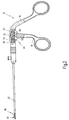
- Fig. 1 a disposable medical forceps system provided with the general reference numeral 10 is shown.
- the forceps system 10 is used without limitation in ear, nose and throat medicine or surgery.
- the forceps system 10 has a first handle 12 and a second handle 14.
- the first handle 12 has a first movable grip part 16 and a first immovable grip part 18.
- the second handle 14 has a second movable grip part 20 and a second immovable grip part 22.
- the first handle 12 is designed to generate a maximum force that is less than the maximum force that can be generated with the second handle 14. This is realized in the embodiment shown in that the first movable handle part 16 of the first handle 12 with respect to a first pivot axis 24 has a smaller lever length than the second movable handle portion 20 with respect to a second pivot axis 26.
- a first working insert 28 and a shaft 30 are shown, wherein the assembly of the work insert 28 and the shaft 30 can be connected to the first handle 12, wherein Fig. 1 the work insert 28 and the shaft 30 are removed from the handle 12.
- the first work insert 28 has a first force transmission element 32, which is connected on the one hand distally with a movable tool 34, which is formed for example as a movable cutting, punching or grasping jaw part.
- the power transmission element 32 is in the form of a pull / push rod. A proximal end of the power transmission element 32, which in Fig.
- Fig. 1 is not shown, is used for frictional connection with the first handle 12, more specifically with the first movable handle portion 16 so that a movement of the first movable handle member 16 is converted into an axial movement of the first power transmission element 32, the latter moves the distal tool 34 ,
- the first working insert 28 is detached from the shaft 30 and shown slightly distally pulled out of the shaft 30, so that the proximal end of the first force-transmitting element 32 in Fig. 1 is not visible.
- a second work insert 36 with a second power transmission element 38, a second distal movable tool 40 and a second shaft 42 is shown.
- the first power transmission element 32 which is frictionally connectable to the first handle 12, may be one which is designed for a power transmission of a high maximum force, as shown schematically and enlarged in the cutout A in Fig. 1 is shown, or such a force transmission element, which is designed for power transmission of a low maximum force, as shown in the cut B in Fig. 1 is shown. Accordingly, the force transmission element shown in the section B is formed with a lower thickness than the force transmission element shown in section A.
- the second handle 14 which is designed to generate large forces, can only be frictionally connected with such a force transmission element 38, which is correspondingly designed for the transmission of high forces, as in the cutout C in FIG Fig. 1 is shown, the the cutout A in Fig. 1 equivalent.
- the first power transmission member 32 will be described as one adapted to transmit a low maximum force, and the second power transmission member 38 as one adapted to transmit a high maximum force, that is greater than the maximum Force that can be transmitted to the first power transmission element 32.
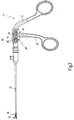
- a pliers composed of the first handle 12 and the second shaft 42 together with the second working insert 36 and distal tool 40 including the force transmission element 38 is shown.
- the force transmission element 38 has at its proximal end a second connecting element 44, which is of spherical design.
- the handle 12 has a coupling device 46 for non-positive connection of the force-transmitting element 38 with the handle 12, more particularly the movable handle part 16.
- the connecting element 44 is locked to the first coupling device, so that the in Fig. 2 shown pliers is ready.
- Fig. 3 is in the same graphic representation as in Fig. 2 a pliers composed of the handle 14 and the work insert 36 with shaft 42 and power transmission element 38 is shown, wherein the handle 14 has a coupling device 48 which will be described in more detail below.
- the coupling device 46 has a slider 50 which is axially movable in a handle housing 52 of the handle 12, i. In the longitudinal direction of the shaft 42 and the power transmission element 38.
- the coupling device 46 further comprises a coupling element 54 which is arranged in a blind hole receptacle 56 of the slider 50, wherein the first coupling element 54 relative to the slider 50 is axially immovable in the blind hole receptacle 56th However, about an axis 58 which is perpendicular to the longitudinal direction of the power transmission element 38, is rotatably movable.
- the first coupling element 54 is in Fig. 7 in isolation and shown enlarged again.
- the slider 50 has a recess 60, in which a driving pin 62 of the first movable grip member 16 engages, so that upon pivoting of the first movable grip member 16 about the pivot axis 24 of the carriage 50 in the axial direction to the distal or proximal, depending on the pivoting direction of the Handle part 16, is moved axially.
- the coupling element 54 has a recess 64 formed in the coupling element 54 for receiving the non-positive connection of the connecting element 44 of the force-transmitting element 38.
- the receptacle 64 is designed to be substantially spherical in cross section, so that the spherically shaped connecting element 44 can be accommodated in the receptacle 64 in a form-fitting manner.
- the receptacle 64 has in more detail a receiving portion 66, in which the second connecting element 44 comes to lie in the frictionally connected state, and a locking portion 68 which has a slot which engages over the force transmitting element 38 distally in front of the connecting element 44 and has a width which smaller than the maximum cross-section of the connecting element 44 is as shown Fig. 4b ).
- the locking portion 68 extends in the circumferential direction about the axis of rotation 58 laterally from the receiving portion 66 away. In this embodiment, there is a positive connection between the connecting element 44 and the receptacle 64 in the locked state.
- the coupling element 54 is in the blind hole receiving 56 by about 90 ° - which rotation may correspond to another angle of rotation - rotatable about the axis of rotation 58, between a first position (insertion position), in Fig. 4a ), and a second position (locking position), which in Fig. 4b ) is shown.
- the power transmission element 38 is non-positively connected to the coupling device 46 and thus to the handle 12 and the movable handle portion 16.
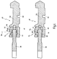
- Fig. 5a ) and b) is now shown that not only the designed for a high power transmission force transmission element 38 can be positively connected to the coupling device 46, but also designed for a power transmission of a lower maximum force force transmission element 32 can be positively connected.
- the power transmission member 32 is formed with a lesser thickness than the power transmission member 38 as a whole, and has at its proximal end a connecting member 70 which, although spherical like the second connecting member 44, differs from the latter in its cross-sectional size, i. is smaller.
- connecting element 70 and the connecting element 44 do not differ or not only with respect to their cross-sectional size, but also embodiments are possible in which the connecting elements 70 and 44 differ in their cross-sectional shape.
- first Connecting element 70 instead of spherical cuboid, cylindrical or be formed as flattening, just to name examples.
- the coupling device 46 has a receptacle 72 for the first connecting element 70, which is axially spaced from the receptacle 64, wherein the receptacle 72 is arranged proximally of the receptacle 64.
- the receptacle 72 in turn has a receiving portion 74, which is partially formed in the illustrated embodiment in the carriage 50. However, the receiving portion 74 may also be arranged completely in the coupling element 54.
- the receptacle 72 further has a locking portion 76 which has a slot which engages over the force-transmitting element 32 distally in front of the connecting element 70 and has a width which is smaller than the maximum cross-section of the connecting element 70.
- Fig. 7 extends the locking portion 76 in the circumferential direction about the axis of rotation 58 laterally from the receiving portion 74, in the same direction of rotation as the locking portion 68 of the receptacle 64th
- Fig. 5a shows the coupling element 54 in turn in the insertion position in which the power transmission element 32 can be inserted with the connecting element 70 in the front in the receptacle 72, or can be pulled out again
- Fig. 5b shows the coupling element 54 in a rotated about the axis of rotation 58 by 90 ° relative to the insertion position locking position in which the power transmission element 32 is non-positively connected to the coupling device 46.
- the connecting element 70 engages through the receptacle 64 when it is connected to the receptacle 72.
- the receptacle 64 is correspondingly formed with a suitably large cross-section.
- the length of the power transmission elements 32 and 38 is preferably different, so that regardless of the Power transmission element 32 or 38, the tool 34 or 40 at the distal end at the same distance from the handle 12 is located.
- either the power transmission element 32 or the power transmission element 38 can thus be connected non-positively. Since the handle 12 can only produce a maximum force that the power transmission element 32 can withstand, there is no or only a small risk of breakage when the "weaker" power transmission element 32 is connected to the handle 12.
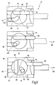
- the handle 14 which is designed to generate higher forces, on the other hand, as will be described below, non-positively connected only with the second power transmission element 38, while the first power transmission element 32 is not frictionally connected to the second handle 14.
- the coupling device 48 has a slider 78, which is preferably identical to the slider 50 of the coupling device 46, which reduces the manufacturing costs, because for the handle 12 and the handle 14 at least partially identical components can be used.
- the function of the slider 78 is identical to the function of the slider 50, as already described above.
- the coupling device 48 further comprises a coupling element 80, which is also identical to the coupling element 54 except for the following exception.
- the coupling element 80 has only one receptacle 82 which is identical to the receptacle 64 of the coupling element 54.
- the receptacle 72 of the coupling element 54 is missing. This has the consequence that the connecting element 70 of the force transmission element 32 in the in Fig. 6a ) insertion into the receptacle 82, however, is between the receptacle 82 and the connecting element 70 upon rotation of the coupling element 80 in its locking position according to Fig. 6b ) no frictional connection of the connecting member 70 made with the receptacle 82, because the connecting element 70 has a smaller cross-section than the locking portion 84 of the receptacle 82nd
- the handle 14 thus has a coding property, which allows only a non-positive connection of the stronger power transmission element 38 with the handle 14, but not a frictional connection of the weaker dimensioned power transmission element 32 with the handle 14.
- FIG. 8a ) to c) are plan views of the partially shown slider 50 and the coupling element 54th
- the coupling element 54 has a first control cam 86, which is formed in the form of a slot-shaped exception, which is also in Fig. 7 you can see.
- the coupling element 54 further has a second control cam 88, which is also formed as a slot-shaped recess, but in contrast to the first control cam 86 assumes a curved course.
- the first cam 86 is open at one end 90 and the second cam 88 at one end 92, wherein the ends 90 and 92 with respect to the axis of rotation 58, the in Fig. 8a ) to c) is perpendicular to the plane of the drawing, offset by about 180 °.
- the slider 50 has two recesses 94 and 96.
- two guide elements 98 and 100 are provided, which are immovable and, for example, attached to the inside of the handle housing 52.
- Fig. 8a shows the coupling element 54 in its insertion position, in which the power transmission element 32 or the power transmission element 38 can be introduced with their respective connecting element 44 or 70 ahead in the respective first or second receptacle described above.
- the guide member 100 is in this position with the second control cam 88 in engagement.
- the axial mobility of the slider 50 is limited in the operational state of operation of the forceps described above by a stop which is formed by a proximal shaft edge. Only by loosening, for example, the shaft 42 of the handle 12 (see. Fig. 1 and Fig. 2 ), the slider 50 can be axially moved beyond its working range corresponding to the axial movement stroke, which is required for actuating, for example.
Description
Die Erfindung betrifft ein zerlegbares medizinisches Zangensystem, mit einem ersten Kraftübertragungselement, das zur Kraftübertragung einer ersten maximalen Kraft ausgelegt ist, mit zumindest einem zweiten Kraftübertragungselement, das zur Kraftübertragung einer zweiten maximalen Kraft ausgelegt ist, die größer ist als die erste maximale Kraft, und mit zumindest einem ersten Griff, der zumindest ein bewegliches Griffteil aufweist, wobei der zumindest eine erste Griff eine Kupplungsvorrichtung aufweist, mittels der eines der Kraftübertragungselemente kraftschlüssig mit dem beweglichen Griffteil verbunden werden kann, wobei das erste Kraftübertragungselement ein erstes Verbindungselement und das zumindest zweite Kraftübertragungselement ein zweites Verbindungselement zur jeweiligen Verbindung der Kupplungsvorrichtung aufweist, wobei die Kupplungsvorrichtung eine erste Aufnahme, die zur kraftschlüssigen Verbindung mit dem ersten Verbindungselement ausgelegt ist, und zumindest eine zweite Aufnahme aufweist, die zur kraftschlüssigen Verbindung mit dem zweiten Verbindungselement ausgelegt ist.The invention relates to a collapsible medical forceps system, comprising a first force transmission element, which is designed for transmitting a first maximum force, with at least one second force transmission element, which is designed to transmit a second maximum force, which is greater than the first maximum force, and with at least a first handle, which has at least one movable grip part, wherein the at least one first handle has a coupling device, by means of which one of the force transmission elements can be frictionally connected to the movable grip part, wherein the first force transmission element, a first connection element and the at least second force transmission element, a second Connecting element to the respective connection of the coupling device, wherein the coupling device has a first receptacle, which is designed for non-positive connection with the first connecting element, and at least a second receptacle, which is designed for non-positive connection with the second connecting element.
Ein solches zerlegbares medizinisches Zangensystem ist aus dem Dokument
Ein zerlegbares medizinisches Zangensystem ist unter der Marke CLICKline® bekannt, das von der Karl Storz GmbH & Co. KG vertrieben wird und beispielsweise in dem Firmenkatalog "
Medizinische Zangen werden in der offenen oder in der endoskopischen Chirurgie beispielsweise zum Schneiden, Fassen, Koagulieren, usw. von Gewebe im menschlichen oder tierischen Körper verwendet.Medical forceps are used in open or endoscopic surgery, for example for cutting, grasping, coagulating, etc. of tissue in the human or animal body.
Eine medizinische Zange weist allgemein einen Griff mit zumindest einem beweglichen Griffteil, einen lang erstreckten Schaft, der mit dem Griff verbunden ist, zumindest ein bewegliches Werkzeug, beispielsweise Maulteil, am distalen Ende des Schafts sowie ein Kraftübertragungselement auf, üblicherweise in Form einer Zug- und Druckstange, das das zumindest eine bewegliche Werkzeug mit dem zumindest einen beweglichen Griffteil des Griffs kraftschlüssig verbindet. Durch Bewegen des zumindest einen beweglichen Griffteils wird die dabei erzeugte Kraft von dem Kraftübertragungselement auf das zumindest eine beweglichen Werkzeug zum Bewegen desselben übertragen.A medical forceps generally include a handle having at least one movable handle portion, an elongated shaft connected to the handle, at least one movable tool, such as a jaw portion, at the distal end of the shaft, and a power transmission element, typically in the form of a pull and pull Push rod, which is the at least one movable tool with the at least one movable handle part of the handle connects frictionally. By moving the at least one movable grip part, the force generated thereby is transmitted from the force transmission element to the at least one movable tool for moving the same.
Aus Gründen der besseren Reinigbarkeit werden solche medizinischen Zangen zerlegbar ausgestaltet, wobei sich eine zerlegbare Zange üblicherweise in die Baugruppen Griff, Schaft und Kraftübertragungselement zerlegen lässt, wobei mit dem Kraftübertragungselement auch das zumindest eine Werkzeug als Baueinheit verbunden sein kann, die auch als Arbeitseinsatz der Zange bezeichnet wird.For reasons of better cleanability, such medical forceps are configured separable, with a collapsible forceps usually disassemble into the assembly handle, shaft and power transmission element, which can be connected to the power transmission element and at least one tool as a unit, which also serves as a labor input of the forceps referred to as.
Die Zerlegbarkeit einer medizinischen Zange erhöht nicht nur die Reinigungsfreundlichkeit der Zange, sondern erhöht auch die Funktionsvariabilität einer solchen Zange, indem verschiedene Griffe mit verschiedenen Schäften und/oder Arbeitseinsätzen kombiniert werden können.The disassembly of a medical forceps not only increases the ease of cleaning the forceps, but also increases the functional variability of such forceps, by combining different handles with different shanks and / or work inserts.
Das bekannte Zangensystem umfasst einerseits mehrere verschiedene Griffe und andererseits eine Mehrzahl an verschiedenen Schäften und Arbeitseinsätzen. So können die Griffe sich hinsichtlich der jeweils erzeugbaren maximalen Kraft unterscheiden, indem beispielsweise Griffe bereitgestellt werden, deren zumindest eines bewegliches Griffteil aufgrund hoher Hebelwirkung eine große Kraft erzeugen kann, während andere Griffe kleiner ausgebildet sind und eine entsprechend kleinere Kraft erzeugen. Eine höhere Kraft ist beispielsweise zum Schneiden bzw. Stanzen von Knochengewebe erforderlich, während zum feinen Präparieren von weicherem Gewebe ein kleinerer Handgriff besser geeignet ist, weil mit ihm die von der Hand des Arztes ausgeübte Kraft besser dosierbar ist.The known pliers system comprises on the one hand several different handles and on the other hand a plurality of different shafts and work inserts. Thus, the handles may differ in the maximum force that can be generated in each case, for example by providing handles whose at least one movable handle part can generate a large force due to high leverage, while other handles are smaller and generate a correspondingly smaller force. A higher force is required, for example, for cutting or punching of bone tissue, while for fine preparation of softer tissue, a smaller handle is better suited, because with him the force exerted by the doctor's hand force is better dosed.
Auch die Kraftübertragungselemente können sich hinsichtlich der mit ihnen maximal übertragbaren Kraft unterscheiden. Die mit dem jeweiligen Kraftübertragungselement maximal übertragbare Kraft ist durch die Dicke bzw. Stärke des Kraftübertragungselements und seines Verbindungselements zur Verbindung mit dem beweglichen Griffteil begrenzt. Zum Schneiden von Knochengewebe muss von dem Griff eine hohe Kraft von dem Kraftübertragungselement auf das zumindest eine Werkzeug am distalen Ende übertragen werden, so dass ein Kraftübertragungselement für diese Zwecke mit einer gewissen Stärke ausgebildet sein muss, beispielsweise einem Durchmesser von 3 mm. Dies bedingt auch einen entsprechend größeren Außendurchmesser des Außenschafts, durch den sich das Kraftübertragungselement zwischen dem Griff und dem zumindest einen Werkzeug erstreckt.Also, the power transmission elements may differ in terms of the maximum transferable power with them. The maximum transferable force with the respective force transmission element is determined by the thickness or strength of the force transmission element and its connecting element for connection to the movable Limited grip. For cutting bone tissue, a high force must be transmitted from the handle to the at least one tool at the distal end of the handle, so that a force transmission element for this purpose must be formed with a certain thickness, for example, a diameter of 3 mm. This also requires a correspondingly larger outer diameter of the outer shaft, through which the force transmission element extends between the handle and the at least one tool.
In räumlich engen Operationsgebieten, wie beispielsweise im Bereich der HNO, sind dagegen sehr schlank bauende Außenschäfte mit geringem Durchmesser erforderlich, so dass das Kraftübertragungselement entsprechend ebenfalls relativ dünn ausgebildet werden muss, beispielsweise mit einem Durchmesser von etwa 1 mm.In spatially narrow operating areas, such as in the field of ENT, on the other hand, very slender outer shells with a small diameter are required, so that the force transmission element must also be made relatively thin accordingly, for example with a diameter of about 1 mm.
Wünschenswert ist es, um eine möglichst hohe Kompatibilität zu erreichen, dass Kraftübertragungselemente, die für die verschiedenen maximal übertragbaren Kräfte ausgelegt sind, mit ein und demselben Griff verbinden werden können, um die Anzahl an bereitzustellenden Griffen möglichst gering zu halten.It is desirable to achieve the highest possible compatibility that power transmission elements, which are designed for the various maximum transferable forces can be connected with one and the same handle to minimize the number of handles to be provided as low as possible.
Das oben genannte bekannte zerlegbare Zangensystem ist jedoch nicht in der Lage, Kraftübertragungselemente mit unterschiedlichen Durchmessern in einem Griff aufzunehmen. Vielmehr sind die Verbindungselemente der Kraftübertragungselemente einerseits und der Kupplungsvorrichtung des oder der Griffe einheitlich ausgebildet, damit möglichst jedes Kraftübertragungselement mit ein und demselben Griff verbunden werden kann. Dies führt jedoch zu den nachstehend erläuterten technischen Problemen, insbesondere wenn Kraftübertragungselemente mit stark unterschiedlichen Stärken und damit Beanspruchbarkeiten in einem Zangensystem zusammengefasst werden sollen.However, the above known collapsible forceps system is incapable of receiving force transmission members of different diameters in a handle. Rather, the connecting elements of the power transmission elements on the one hand and the coupling device of the handle or handles are uniform, so that as far as possible each power transmission element can be connected to one and the same handle. However, this leads to the technical problems explained below, in particular when force transmission elements with greatly differing strengths and, thus, toughness in a tong system are to be combined.
Bei der Vormontage des Arbeitseinssatzes wird das Kraftübertragungselement von distal her durch den Außenschaft geschoben. Das Verbindungselement am proximalen Ende des Kraftübertragungselements, das beispielsweise in Form einer Kugel ausgebildet ist, muss dabei ebenfalls durch den Außenschaft treten können, bis es aus dem proximalen Ende des Außenschafts vorragt. Ist das Kraftübertragungselement nun auf eine große Kraftübertragung ausgelegt, muss auch das Verbindungselement mit entsprechender Stärke ausgelegt sein, damit die Verbindung zwischen dem Kraftübertragungselement und dem Griff insgesamt großen Kräften standhalten kann. Damit das relativ groß dimensionierte Verbindungselement durch den Außenschaft hindurchtreten kann, muss der Außenschaft einen relativ großen Durchmesser aufweisen. Ein solches Zangensystem hat dann den Nachteil, dass bei einer Verbindung des Griffs mit einem dünneren Kraftübertragungselement der Außenschaft dennoch den gleichen großen Durchmesser aufweisen muss wie im Fall der Verbindung eines stärker dimensionierten Kraftübertragungselements mit dem Griff, damit die Kompatibilität zwischen verschiedenen Kraftübertragungselementen und demselben Griff nicht aufgegeben werden muss. Andernfalls müsste ein zweiter Griff mit einer anderen Kupplungsvorrichtung bereitgestellt werden, was jedoch dem Sinn einer höheren Kompatibilität zuwiderläuft und die Anzahl an unterschiedlichen Griffen unerwünscht erhöht.During pre-assembly of the working set, the force transmission element is pushed from the distal side through the outer shaft. The connecting element at the proximal end of the force transmission element, for example in the form of a ball is formed, it must also be able to pass through the outer shaft until it protrudes from the proximal end of the outer shaft. If the power transmission element is now designed for a large force transmission, the connecting element must also be designed with appropriate strength, so that the connection between the force transmission element and the handle can withstand large forces overall. In order for the relatively large-sized connecting element can pass through the outer shaft, the outer shaft must have a relatively large diameter. Such a pliers system then has the disadvantage that when the handle is connected to a thinner power transmission element, the outer shaft must nevertheless have the same large diameter as in the case of the connection of a more strongly dimensioned force transmission element with the handle, so that the compatibility between different power transmission elements and the same handle is not must be abandoned. Otherwise, a second grip would have to be provided with another coupling device, which, however, runs counter to the sense of higher compatibility and undesirably increases the number of different handles.
Wird umgekehrt die Verbindung zwischen dem Kraftübertragungselement und dem Griff auf das Kraftübertragungselement mit kleiner maximaler Kraftübertragung ausgelegt, so dass das Verbindungselement am proximalen Ende des Kraftübertragungselements kleiner dimensioniert werden kann, kann zwar die Außenschaftabmessung variabel und insbesondere dünn gewählt werden, die maximal übertragbare Kraft bleibt aber auf diejenige des kleinsten bzw. schwächsten Kraftübertragungselements begrenzt. Dies bedeutet, dass beim Einsatz von viel Kraft erfordernden Werkzeugen, wie beispielsweise Knochenstanzen, mit einem entsprechend groß dimensionierten Griff, ein Bruch des Kraftübertragungselements im Bereich des Verbindungselements nicht ausgeschlossen werden kann, wenn der Griff mit großer Handkraft betätigt wird.Conversely, if the connection between the power transmission element and the handle on the power transmission element designed with a small maximum power transmission, so that the connecting element can be dimensioned smaller at the proximal end of the power transmission element, although the outer shaft dimension variable and in particular be selected thin, but the maximum transferable force remains limited to that of the smallest or weakest power transmission element. This means that when using tools requiring much force, such as bone punches, with a correspondingly large-sized handle, a breakage of the force transmission element in the region of the connecting element can not be excluded when the handle is operated with great manual force.
Der die Zange betätigende Arzt muss daher in diesem Fall seine Handkraft behutsam dosieren, um einen Bruch des Kraftübertragungselements zu vermeiden.The pliers-pressing doctor must therefore carefully dose his hand force in this case in order to avoid breakage of the power transmission element.
Das bekannte medizinische Zangensystem hat daher den Nachteil, dass die Verbindungselemente der vorhandenen Kraftübertragungselemente auf nur eine Stärkendimensionierung festgelegt sind, was entweder zu unerwünscht großen Außendurchmessern der Außenschäfte oder der Gefahr eines Bruches des Kraftübertragungselements führt.The known medical forceps system therefore has the disadvantage that the connecting elements of the existing power transmission elements are fixed to only one thickness dimensioning, which leads either to undesirably large outer diameters of the outer shafts or the risk of breakage of the power transmission element.
Das aus dem eingangs genannten Dokument
Der Erfindung liegt die Aufgabe zugrunde, ein zerlegbares medizinisches Zangensystem der eingangs genannten Art dahingehend weiterzubilden, dass mit ein und demselben Griff Kraftübertragungselemente mit unterschiedlicher Kraftübertragungsauslegung verbunden werden können, ohne dass dadurch ein Mindestdurchmesser des Außenschaftes festgelegt ist.The invention has the object of developing a collapsible medical forceps system of the type mentioned in that with one and the same handle power transmission elements with different power transmission design can be connected without thereby a minimum diameter of the outer shaft is fixed.
Hinsichtlich des eingangs genannten zerlegbaren medizinischen Zangensystems wird die vorstehend genannte Aufgabe erfindungsgemäß dadurch gelöst, dass sich die Querschnittsgröße und/oder Querschnittsform des ersten Verbindungselements quer zur Längsrichtung des ersten Kraftübertragungselements von der Querschnittsgröße und/oder Querschnittsform des zweiten Verbindungselements quer zur Längsrichtung des zweiten Kraftübertragungselements unterscheidet.With regard to the above-mentioned dismountable medical forceps system, the above-mentioned object is achieved in that the cross-sectional size and / or cross-sectional shape of the first connecting element transversely to the longitudinal direction of the first force transmission element differs from the cross-sectional size and / or cross-sectional shape of the second connecting element transversely to the longitudinal direction of the second force transmission element ,
Das erfindungsgemäße zerlegbare medizinische Zangensystem weist somit zumindest einen Griff auf, mit dem wahlweise zumindest zwei auf unterschiedliche maximale Kraftübertragung ausgelegte Kraftübertragungselemente verbunden werden können. Dazu ist die Kupplungsvorrichtung dieses ersten Griffs mit zumindest zwei Aufnahmen ausgestaltet, wobei die eine Aufnahme dazu ausgelegt ist, das Verbindungselement des ersten Kraftübertragungselements kraftschlüssig mit dem Griff zu verbinden, und die zumindest eine andere Aufnahme dazu ausgelegt ist, das Verbindungselement des zweiten Kraftübertragungselements kraftschlüssig mit demselben Griff zu verbinden. Bei dem erfindungsgemäßen zerlegbaren medizinischen Zangensystem kann somit die Anzahl an bereitzuhaltenden Griffen verringert werden, da ein und derselbe Griff mit unterschiedlichen Kraftübertragungselementen verbunden werden kann. Dies bedeutet weiterhin, dass ein für eine kleinere Kraftübertragung ausgelegtes Kraftübertragungselement, das entsprechend mit geringerer Stärke dimensioniert ist, zusammen mit einem schlankeren Schaft mit dem Griff verbunden werden kann, ebenso wie ein für eine höhere Kraftübertragung ausgelegtes stärker dimensioniertes Kraftübertragungselement, das mit einem entsprechend größer dimensionierten Schaft ebenso mit demselben Griff verbunden werden kann. Es versteht sich, dass die Kupplungsvorrichtung auch mehr als zwei Aufnahmen für mehr als zwei verschieden ausgelegte Kraftübertragungselemente aufweisen kann.The collapsible medical forceps system according to the invention thus has at least one handle, with which optionally at least two force transmission elements designed for different maximum force transmission can be connected. For this purpose, the coupling device of this first handle is configured with at least two receptacles, wherein the one receptacle is designed to non-positively with the connecting element of the first power transmission element to connect the handle, and the at least one other receptacle is adapted to frictionally connect the connecting element of the second power transmission element with the same handle. Thus, in the collapsible medical forceps system of the present invention, the number of handles to be held can be reduced since one and the same handle can be connected to different power transmission members. This also means that a designed for a smaller power transmission force transmission, which is dimensioned accordingly with lower strength, together with a slimmer shaft can be connected to the handle, as well as designed for a higher power transmission larger-sized power transmission element, with a correspondingly larger dimensioned shaft can also be connected to the same handle. It is understood that the coupling device can also have more than two receptacles for more than two differently designed power transmission elements.
Der Begriff "Aufnahme" ist im Sinne der vorliegenden Erfindung allgemein zu verstehen und umfasst alle Ausgestaltungen derselben, die eine kraftschlüssige Verbindung des jeweiligen Verbindungselements mit der Aufnahme ermöglichen.The term "receptacle" is to be understood in the context of the present invention in general and includes all embodiments thereof, which allow a frictional connection of the respective connecting element with the receptacle.
Im einfachsten Fall ist das erste Verbindungselement, wie in einer weiteren bevorzugten Ausgestaltung vorgesehen, kugelförmig mit einem ersten Durchmesser und das zweite Verbindungselement kugelförmig mit einem zweiten Durchmesser, der größer als der erste Durchmesser ist.In the simplest case, as provided in a further preferred embodiment, the first connecting element is spherical with a first diameter and the second connecting element is spherical with a second diameter which is larger than the first diameter.
Die Ausgestaltung der Verbindungselemente in Kugelform hat den Vorteil einer einfacheren Herstellbarkeit, weil die Verbindungselemente als Drehteile und insbesondere in einem Arbeitsgang einstückig mit dem übrigen Körper des jeweiligen Kraftübertragungselements ausgebildet werden können. Außerdem ermöglicht es die kugelförmige Ausgestaltung der Verbindungselemente, dass sich diese in der jeweiligen Aufnahme trotz der kraftschlüssigen Verbindung um die Längsachse des Kraftübertragungselements drehen lassen, so dass sich das Werkzeug, beispielsweise ein oder mehrere Maulteile am distalen Ende des Instruments, relativ zum Griff drehen lassen, wodurch die Position des Werkzeugs ohne Veränderung der Position des Griffs von der Bedienungsperson verändert werden kann.The design of the connecting elements in spherical shape has the advantage of easier manufacturability, because the connecting elements can be formed as turned parts and in particular in one operation in one piece with the rest of the body of the respective power transmission element. In addition, the spherical configuration of the connecting elements makes it possible for them to rotate in the respective receptacle in spite of the non-positive connection about the longitudinal axis of the force transmission element, so that the tool, for example one or more jaw parts at the distal end of the instrument, rotate relative to the handle leave, whereby the position of the tool without changing the position of the handle can be changed by the operator.
In einer weiteren bevorzugten Ausgestaltung des zerlegbaren medizinischen Zangensystems ist die erste Aufnahme von der zweiten Aufnahme axial beabstandet.In a further preferred embodiment of the collapsible medical forceps system, the first receptacle is axially spaced from the second receptacle.
Hierbei ist von Vorteil, dass die erfindungsgemäß erreichte Möglichkeit, mit demselben Griff unterschiedlich ausgelegte Kraftübertragungselemente verbinden zu können, nicht zu Lasten einer höheren Querabmessung der Kupplungsvorrichtung und damit des Griffs im Bereich der Kupplungsvorrichtung geht, weil die zumindest zwei Aufnahmen der Kupplungsvorrichtung hintereinander in Längsrichtung der Kraftübertragungsrichtung angeordnet sind.It is advantageous that the present invention achieved ability to combine with the same grip differently designed power transmission elements, not at the expense of a higher transverse dimension of the coupling device and thus the handle in the region of the coupling device is because the at least two shots of the coupling device behind the other in the longitudinal direction Power transmission direction are arranged.
In diesem Zusammenhang ist bevorzugt, wenn das erste Verbindungselement durch die zweite Aufnahme hindurchgreift, wenn es in der ersten Aufnahme kraftschlüssig verbunden ist.In this context, it is preferred if the first connecting element engages through the second receptacle when it is non-positively connected in the first receptacle.
Diese Ausgestaltung eignet sich insbesondere dann, wenn das erste und zweite Verbindungselement hinsichtlich ihrer Querschnittsgröße unterschiedlich sind. Das Verbindungselement mit kleinerer Querschnittsgröße kann dann durch die distal gelegene zweite Aufnahme, die zur kraftschlüssigen Verbindung des Verbindungselements mit größerer Querschnittsgröße ausgelegt ist, ungehindert hindurchgreifen, um mit der ersten proximal gelegenen Aufnahme kraftschlüssig verbunden werden zu können. In dieser Ausgestaltung wird insbesondere der vorstehend genannte Vorteil einer sehr schlankbauenden Kupplungsvorrichtung noch besser verwirklicht.This embodiment is particularly suitable when the first and second connecting element are different in cross-sectional size. The connecting element with a smaller cross-sectional size can then pass unhindered through the distal second receptacle, which is designed for frictional connection of the connecting element with a larger cross-sectional size, in order to be able to be frictionally connected to the first proximal receptacle. In this embodiment, in particular the above-mentioned advantage of a very slim-fitting coupling device is realized even better.
In einer weiteren bevorzugten Ausgestaltung des Zangensystems weist die Kupplungsvorrichtung ein zwischen einer ersten Stellung und einer zweiten Stellung bewegliches Kupplungselement auf, das die erste und die zumindest zweite Aufnahme zumindest teilweise aufweist, wobei in der ersten Stellung das erste oder das zumindest zweite Verbindungselement in die erste oder zweite Aufnahme einführbar oder herausnehmbar ist, und in der zweiten Stellung das erste oder das zumindest zweite Verbindungselement in der ersten bzw. zweiten Aufnahme verriegelt ist.In a further preferred embodiment of the pliers system, the coupling device has a coupling element which is movable between a first position and a second position and which has the first and the at least second receptacles at least partially, wherein in the first position the first or the at least second connecting element is insertable or removable in the first or second receptacle, and in the second position, the first or the at least second connecting element is locked in the first or second receptacle.
Die Ausgestaltung der Kupplungsvorrichtung mit einem zwischen einer Einführstellung und einer Verriegelungsstellung beweglichen Kupplungselement hat den Vorteil, dass das kraftschlüssige Verbinden des jeweiligen Kraftübertragungselements mit dem Griff auf einfach handhabbare Weise erfolgen kann, und insbesondere, wenn das Kupplungselement mit einem Steuermechanismus versehen ist, vorzugsweise auf automatische Weise.The design of the coupling device with a movable between an insertion and a locking position coupling element has the advantage that the frictional connection of the respective power transmission element with the handle can be done in an easy to handle manner, and in particular when the coupling element is provided with a control mechanism, preferably automatic Wise.
Dabei ist es bevorzugt, wenn das Kupplungselement durch eine Drehbewegung von der ersten Stellung in die zweite Stellung bzw. umgekehrt bewegbar ist, wobei das Kupplungselement mit einem axial beweglichen Schieber, der mit dem beweglichen Griffteil verbunden ist, verbunden ist und relativ zum Schieber axial unbeweglich ist, und wobei die Drehbewegung aus einer axialen Bewegung des Schiebers abgeleitet wird.It is preferred if the coupling element is movable by a rotational movement from the first position to the second position or vice versa, wherein the coupling element with an axially movable slide, which is connected to the movable handle part, connected and relative to the slide axially immovable is, and wherein the rotational movement is derived from an axial movement of the slider.
Durch die Mitnahme des Kupplungselements bei einer axialen Bewegung des Schiebers beim kraftschlüssigen Verbinden des ersten oder zweiten Verbindungselements mit dem Kupplungselement wird das Kupplungselement somit vorteilhafterweise selbsttätig von der Einführstellung in die Verriegelungsstellung gedreht und beim Entriegeln entsprechend umgekehrt.By the entrainment of the coupling element in an axial movement of the slide in the non-positive connection of the first or second connecting element with the coupling element, the coupling element is thus advantageously automatically rotated from the insertion position into the locking position and reversed accordingly when unlocking.
In einer weiteren bevorzugten Ausgestaltung weist die erste Aufnahme einen Aufnahmeabschnitt, in dem das erste Verbindungselement im kraftschlüssig verbundenen Zustand zu liegen kommt, und einen Verriegelungsabschnitt auf, der einen Schlitz aufweist, der das Kraftübertragungselement distal vor dem ersten Verbindungselement übergreift und eine Breite aufweist, die kleiner als der maximale Querschnitt des ersten Verbindungselements ist.In a further preferred refinement, the first receptacle has a receiving section, in which the first connecting element comes to lie in the frictionally connected state, and a locking section, which has a slot comprising, which engages over the force transmitting element distally in front of the first connecting element and has a width which is smaller than the maximum cross section of the first connecting element.
Ebenso bevorzugt und entsprechend weist die zweite Aufnahme einen Aufnahmeabschnitt, in dem das zweite Verbindungselement im kraftschlüssig verbundenen Zustand zu liegen kommt, und einen Verriegelungsabschnitt auf, der einen Schlitz aufweist, der das Kraftübertragungselement distal vor dem zweiten Verbindungselement übergreift und eine Breite aufweist, die kleiner als der maximale Querschnitt des zweiten Verbindungselements ist.Also preferably and correspondingly, the second receptacle has a receiving portion in which the second connecting element comes to lie in the frictionally connected state, and a locking portion having a slot which engages over the force transmission element distally in front of the second connecting element and has a width which is smaller as the maximum cross-section of the second connecting element.
Diese vorstehend genannten Ausgestaltungen sind insbesondere mit der drehbaren Ausgestaltung des zuvor genannten Kupplungselements von Vorteil, weil sich die kraftschlüssige Verbindung zwischen dem ersten bzw. zweiten Kraftübertragungselement und der ersten bzw. zweiten Aufnahme sehr einfach gestaltet, indem nämlich das erste bzw. zweite Verbindungselement zunächst in der Einführstellung des Kupplungselements in den Aufnahmeabschnitt eingeführt werden kann, wonach das Kupplungselement um eine Drehung, beispielsweise um 90°, um eine senkrecht zur Längsrichtung des jeweiligen Kraftübertragungselements verlaufenden Drehachse gedreht wird, wodurch die Ränder des jeweiligen Schlitzes das jeweilige Kraftübertragungselement distal vor dessen Verbindungselement übergreifen, um eine besonders stabile und möglichst spielfreie kraftschlüssige Verbindung des jeweiligen Kraftübertragungselements in der jeweiligen Aufnahme herzustellen.These abovementioned embodiments are particularly advantageous with the rotatable embodiment of the aforementioned coupling element because the frictional connection between the first and second force transmission element and the first and second receptacle is very simple, namely by firstly connecting the first and second connection element in FIG the insertion of the coupling element can be introduced into the receiving portion, after which the coupling element is rotated by a rotation, for example by 90 °, about a perpendicular to the longitudinal direction of the respective force transmission element axis of rotation, whereby the edges of the respective slot engage over the respective force transmission element distally in front of the connecting element In order to produce a particularly stable and play-free frictional connection of the respective power transmission element in the respective recording.
In einer weiteren bevorzugten Ausgestaltung des Zangensystems umfasst dieses zumindest einen zweiten Griff, der zumindest ein bewegliches Griffteil aufweist, wobei der zumindest eine zweite Griff eine zweite Kupplungsvorrichtung aufweist, mittels der nur das zweite Kraftübertragungselement kraftschlüssig mit dem beweglichen Griffteil verbunden werden kann, während eine kraftschlüssige Verbindung mit dem ersten Kraftübertragungselement ausgeschlossen ist.In a further preferred embodiment of the pliers system, the latter comprises at least one second handle, which has at least one movable grip part, wherein the at least one second grip has a second coupling device, by means of which only the second force transmission element can be frictionally connected to the movable grip part, while a frictional grip Connection is excluded with the first power transmission element.
Diese Ausgestaltung hat nun den besonderen Vorteil, dass das Zangensystem einerseits eine Art Griffe aufweist, die es erlauben, mit demselben Griff unterschiedlich dimensionierte bzw. für unterschiedliche Kraftübertragung ausgelegte Kraftübertragungselemente mit demselben Griff zu verbinden, wobei diese Griffe hinsichtlich ihrer maximalen Krafterzeugung so ausgelegt sind, dass auch das schwächer dimensionierte Kraftübertragungselement nicht einer Bruchgefahr unterliegt, während das Zangensystem zumindest eine zweite Art von Griffen umfasst, die für eine höhere Krafterzeugung ausgelegt sind, während mit dieser Art Griffen ausschließlich entsprechend stärker dimensionierte Kraftübertragungselemente kraftschlüssig verbunden werden können. In dieser Ausgestaltung werden somit die Vorteile der oben genannten Codierung von Kraftübertragungselementen auf bestimmte Griffe und zum anderen die Anzahl an Kombiniermöglichkeiten verschiedener Kraftübertragungselemente mit ein und demselben Griff in einem Zangensystem miteinander kombiniert.This embodiment has the particular advantage that the pliers system on the one hand has a kind of handles that allow to connect with the same handle differently dimensioned or designed for different power transmission force transmission elements with the same handle, these handles are designed in terms of their maximum power generation so that the weaker dimensioned power transmission element is not subject to a risk of breakage, while the pliers system comprises at least a second type of handles, which are designed for higher force generation, while only exclusively correspondingly larger-sized force transmission elements can be non-positively connected with this type of handles. In this embodiment, thus, the advantages of the above coding of power transmission elements on certain handles and on the other hand, the number of Kombiniermöglichkeiten different power transmission elements combined with one and the same handle in a pliers system.
In diesem Zusammenhang ist es weiter bevorzugt, wenn die zweite Kupplungsvorrichtung eine Aufnahme für das zweite Verbindungselement aufweist, die so ausgebildet ist, dass das erste Verbindungselement in der Aufnahme nicht verriegelt werden kann.In this context, it is further preferred if the second coupling device has a receptacle for the second connecting element, which is formed such that the first connecting element in the receptacle can not be locked.
Diese Maßnahme hat den Vorteil, dass bereits bei der ersten Betätigung des Griffs für die Bedienungsperson erkennbar keine Kraftübertragung vom Griff auf das Werkzeug vorhanden ist, so dass ein Fehlgebrauch von vornherein ausgeschlossen ist.This measure has the advantage that even at the first actuation of the handle for the operator recognizable no power transmission from the handle on the tool is present, so that misuse is excluded from the outset.
Dabei ist es weiterhin bevorzugt, wenn die Aufnahme der zweiten Kupplungsvorrichtung gleich oder im Wesentlichen gleich zu der zweiten Aufnahme der ersten Kupplungsvorrichtung ausgebildet ist.In this case, it is further preferred if the receptacle of the second coupling device is formed to be the same or substantially equal to the second receptacle of the first coupling device.
Beispielsweise kann die zweite Kupplungsvorrichtung ebenfalls als drehbares Kupplungselement ausgebildet sein, bei dem dann im Unterschied zu dem Kupplungselement der ersten Kupplungsvorrichtung nur die zweite Aufnahme vorhanden ist, während die erste Aufnahme bei diesem Kupplungselement fehlt. Der Vorteil dieser Maßnahme besteht darin, dass für das gesamte Zangensystem im Wesentlichen gleiche Teile verwendet werden können, wobei nur geringfügige Modifikationen für die unterschiedlichen Funktionen vorgenommen werden müssen, was die Herstellungskosten des erfindungsgemäßen Zangensystems reduziert.For example, the second coupling device may also be designed as a rotatable coupling element, in which then, in contrast to the coupling element of the first coupling device, only the second receptacle is present, while the first picture is missing at this coupling element. The advantage of this measure is that substantially the same parts can be used for the entire forceps system, with only minor modifications to the different functions must be made, which reduces the manufacturing cost of the forceps system according to the invention.
Weitere Vorteile und Merkmale ergeben sich aus der nachfolgenden Beschreibung und der beigefügten Zeichnung.Further advantages and features will become apparent from the following description and the accompanying drawings.
Es versteht sich, dass die vorstehend genannten und nachstehend noch zu erläuternden Merkmale nicht nur in der jeweils angegebenen Kombination, sondern auch in anderen Kombinationen oder in Alleinstellung verwendbar sind, ohne den Rahmen der vorliegenden Erfindung zu verlassen.It is understood that the features mentioned above and those yet to be explained can be used not only in the particular combination given, but also in other combinations or in isolation, without departing from the scope of the present invention.
Ausführungsbeispiele der Erfindung sind in der Zeichnung dargestellt und werden mit Bezug auf diese hiernach näher beschrieben. Es zeigen:
- Fig. 1
- ein zerlegbares medizinisches Zangensystem, wobei beispielhaft zwei Zangen in zerlegtem Zustand gezeigt sind;
- Fig. 2
- eine der beiden Zangen in
Fig. 1 in zusammengesetztem Zustand, teilweise im Längsschnitt; - Fig. 3
- die andere der beiden Zangen in
Fig. 1 im zusammengesetzten Zustand, teilweise im Längsschnitt; - Fig. 4a) und b)
- eine Kupplungsvorrichtung der Zange in
Fig. 2 im vergrößerten Maßstab und im Längsschnitt, wobei gemäßFig. 4a ) ein Kraftübertragungselement in die Kupplungsvorrichtung eingeführt und gemäßFig. 4b ) in dieser verriegelt ist; - Fig. 5a) und b) Fig. 4a) und b)
- entsprechende Darstellungen der Verbindung eines weiteren Kraftübertragungselements mit der Kupplungsvorrichtung in
Fig. 4a ) und b); - Fig. 6
- eine Kupplungsvorrichtung der Zange in
Fig. 3 im vergrößerten Maßstab und im Längsschnitt, wobei inFig. 6a ) das Kraftübertragungselement gemäßFig. 4a ) in die Kupplungsvorrichtung eingeführt ist, undFig. 6b ) zeigt, dass dieses erste Kraftübertragungselement nicht mit dieser Kupplungsvorrichtung kraftschlüssig verbunden werden kann; - Fig. 7
- ein Kupplungselement der Kupplungsvorrichtung in
Fig. 4 und5 in einer perspektivischen Darstellung und in noch weiter vergrößertem Maßstab; und - Fig. 8a) bis c)
- schematische Darstellungen der Kupplungsvorrichtung in
Fig. 4 ,5 oder6 in Draufsicht zur Erläuterung eines Steuermechanismus zum Überführen des Kupplungselements von einer Einführstellung gemäßFig. 8a ) in eine Verriegelungsstellung gemäßFig. 8c ).
- Fig. 1
- a collapsible medical forceps system, wherein two forceps are shown in disassembled state by way of example;
- Fig. 2
- one of the two pliers in
Fig. 1 in assembled condition, partly in longitudinal section; - Fig. 3
- the other of the two pliers in
Fig. 1 in the assembled state, partly in longitudinal section; - Fig. 4a) and b)
- a coupling device of the pliers in
Fig. 2 on an enlarged scale and in longitudinal section, according toFig. 4a ) A force transmission element is inserted into the coupling device and according toFig. 4b ) is locked in this; - Fig. 5a) and b) Fig. 4a) and b)
- corresponding representations of the connection of another power transmission element with the coupling device in
Fig. 4a ) and b); - Fig. 6
- a coupling device of the pliers in
Fig. 3 on an enlarged scale and in longitudinal section, inFig. 6a ) According to the power transmission elementFig. 4a ) is introduced into the coupling device, andFig. 6b ) shows that this first power transmission element can not be frictionally connected to this coupling device; - Fig. 7
- a coupling element of the coupling device in
Fig. 4 and5 in a perspective view and on a further enlarged scale; and - 8a) to c)
- schematic representations of the coupling device in
Fig. 4 .5 or6 in plan view for explaining a control mechanism for transferring the coupling element from an insertion position according toFig. 8a ) in a locking position according toFig. 8c ).
In
Das Zangensystem 10 weist einen ersten Griff 12 und einen zweiten Griff 14 auf. Der erste Griff 12 weist ein erstes bewegliches Griffteil 16 und ein erstes unbewegliches Griffteil 18 auf. Ebenso weist der zweite Griff 14 ein zweites bewegliches Griffteil 20 und ein zweites unbewegliches Griffteil 22 auf.The
Der erste Griff 12 ist zur Erzeugung einer maximalen Kraft ausgelegt, die kleiner ist als die maximale Kraft, die mit dem zweiten Griff 14 erzeugt werden kann. Dies ist in dem gezeigten Ausführungsbeispiel dadurch realisiert, dass das erste bewegliche Griffteil 16 des ersten Griffs 12 in Bezug auf eine erste Schwenkachse 24 eine kleinere Hebellänge besitzt als das zweite bewegliche Griffteil 20 in Bezug auf eine zweite Schwenkachse 26.The
In
Weiterhin ist in
Das erste Kraftübertragungselement 32, das mit dem ersten Griff 12 kraftschlüssig verbindbar ist, kann ein solches sein, das für eine Kraftübertragung einer hohen maximalen Kraft ausgelegt ist, wie es schematisch und vergrößert in dem Ausschnitt A in
Demgegenüber ist der zweite Griff 14, der zur Erzeugung großer Kräfte ausgelegt ist, nur mit einem solchen Kraftübertragungselement 38 kraftschlüssig verbindbar, das entsprechend zur Kraftübertragung hoher Kräfte ausgelegt ist, wie in dem Ausschnitt C in
In der nachfolgenden Beschreibung wird das erste Kraftübertragungselement 32 als ein solches beschrieben, das zur Kraftübertragung einer niedrigen maximalen Kraft ausgelegt ist, und das zweite Kraftübertragungselement 38 als ein solches, das zur Kraftübertragung einer hohen maximalen Kraft ausgelegt ist, die also größer ist als die maximale Kraft, die mit dem ersten Kraftübertragungselement 32 übertragen werden kann.In the following description, the first
In
In
Zunächst wird mit Bezug auf
Die Kupplungsvorrichtung 46 weist einen Schieber 50 auf, der in einem Griffgehäuse 52 des Griffs 12 axial beweglich ist, d.h. in Längsrichtung des Schafts 42 bzw. des Kraftübertragungselements 38. Die Kupplungsvorrichtung 46 weist weiterhin ein Kupplungselement 54 auf, das in einer Sacklochaufnahme 56 des Schiebers 50 angeordnet ist, wobei das erste Kupplungselement 54 relativ zu dem Schieber 50 axial unbeweglich ist, in der Sacklochaufnahme 56 jedoch um eine Achse 58, die senkrecht zur Längsrichtung des Kraftübertragungselements 38 verläuft, drehbeweglich ist.The
Das erste Kupplungselement 54 ist in
Der Schieber 50 weist eine Ausnehmung 60 auf, in die ein Mitnehmerstift 62 des ersten beweglichen Griffteils 16 eingreift, so dass bei einer Verschwenkung des ersten beweglichen Griffteils 16 um die Schwenkachse 24 der Schlitten 50 in axialer Richtung nach distal oder proximal, je nach Schwenkrichtung des Griffteils 16, axial bewegt wird.The
Das Kupplungselement 54 weist eine als Ausnehmung in dem Kupplungselement 54 ausgebildeten Aufnahme 64 zur kraftschlüssigen Verbindung des Verbindungselements 44 des Kraftübertragungselements 38 auf. Die Aufnahme 64 ist im Querschnitt dazu im Wesentlichen kugelförmig ausgebildet, so dass das kugelförmig ausgebildete Verbindungselement 44 formschlüssig in der Aufnahme 64 aufgenommen werden kann.The
Die Aufnahme 64 weist genauer einen Aufnahmeabschnitt 66, in dem das zweite Verbindungselement 44 im kraftschlüssig verbundenen Zustand zu liegen kommt, und einen Verriegelungsabschnitt 68 auf, der einen Schlitz aufweist, der das Kraftübertragungselement 38 distal vor dem Verbindungselement 44 übergreift und eine Breite aufweist, die kleiner als der maximale Querschnitt des Verbindungselements 44 ist, wie aus
Das Kupplungselement 54 ist in der Sacklochaufnahme 56 um etwa 90° - wobei diese Drehung auch einem anderen Verdrehwinkel entsprechen kann - um die Drehachse 58 drehbar, und zwar zwischen einer ersten Stellung (Einführstellung), die in
Später wird noch beschrieben, wie die Drehbewegung des Kupplungselements 54 aus einer axialen Bewegung des Schiebers 50 heraus abgeleitet wird.It will be described later how the rotational movement of the
In
Das Kraftübertragungselement 32 ist gegenüber dem Kraftübertragungselement 38 insgesamt mit geringerer Stärke ausgebildet und weist an seinem proximalen Ende ein Verbindungselement 70 auf, das zwar ebenfalls wie das zweite Verbindungselement 44 kugelförmig ausgebildet ist, sich jedoch von Letzterem hinsichtlich seiner Querschnittsgröße unterscheidet, d.h. kleiner ist.The
Abweichend von dem gezeigten Ausführungsbeispiel ist es jedoch ebenso möglich, dass sich das Verbindungselement 70 und das Verbindungselement 44 nicht oder nicht nur hinsichtlich ihrer Querschnittsgröße unterscheiden, sondern es sind auch Ausgestaltungen möglich, bei denen sich die Verbindungselemente 70 und 44 hinsichtlich ihrer Querschnittsform unterscheiden. Beispielsweise kann das erste Verbindungselement 70 anstatt kugelförmig quaderförmig, zylinderförmig oder als Abflachungen ausgebildet sein, nur um Beispiele zu nennen.Deviating from the embodiment shown, however, it is also possible that the connecting
Die Kupplungsvorrichtung 46 weist für das erste Verbindungselement 70 eine Aufnahme 72 auf, die von der Aufnahme 64 axial beabstandet ist, wobei die Aufnahme 72 proximal von der Aufnahme 64 angeordnet ist.The
Die Aufnahme 72 weist wiederum einen Aufnahmeabschnitt 74 auf, der in dem gezeigten Ausführungsbeispiel teilweise auch in dem Schlitten 50 ausgebildet ist. Der Aufnahmeabschnitt 74 kann jedoch auch vollständig in dem Kupplungselement 54 angeordnet sein.The
Die Aufnahme 72 weist des Weiteren einen Verriegelungsabschnitt 76 auf, der einen Schlitz aufweist, der das Kraftübertragungselement 32 distal vor dem Verbindungselement 70 übergreift und eine Breite aufweist, die kleiner als der maximale Querschnitt des Verbindungselements 70 ist. Gemäß
Das Verbindungselement 70 greift durch die Aufnahme 64 hindurch, wenn es mit der Aufnahme 72 verbunden ist. Dazu ist die Aufnahme 64 entsprechend mit einem geeignet großen Querschnitt ausgebildet. Die Länge der Kraftübertragungselemente 32 und 38 ist vorzugsweise unterschiedlich, so dass sich unabhängig vom dem Kraftübertragungselement 32 oder 38 das Werkzeug 34 oder 40 am distalen Ende im gleichen Abstand vom Griff 12 befindet.The connecting
Mit dem Griff 12 kann somit wahlweise das Kraftübertragungselement 32 oder das Kraftübertragungselement 38 kraftschlüssig verbunden werden. Da der Griff 12 nur eine maximale Kraft erzeugen kann, dem das Kraftübertragungselement 32 standhalten kann, besteht keine oder nur eine geringe Bruchgefahr, wenn das "schwächere" Kraftübertragungselement 32 mit dem Griff 12 verbunden wird.With the
Der Griff 14, der zur Erzeugung höherer Kräfte ausgelegt ist, ist dagegen, wie nachfolgend beschrieben wird, nur mit dem zweiten Kraftübertragungselement 38 kraftschlüssig verbindbar, während das erste Kraftübertragungselement 32 mit dem zweiten Griff 14 nicht kraftschlüssig verbindbar ist.The
Gemäß
Die Kupplungsvorrichtung 48 weist ferner ein Kupplungselement 80 auf, das mit dem Kupplungselement 54 bis auf folgende Ausnahme ebenfalls identisch ausgebildet ist. Im Unterschied zu dem Kupplungselement 54 weist das Kupplungselement 80 nämlich nur eine Aufnahme 82 auf, die identisch mit der Aufnahme 64 des Kupplungselements 54 ausgebildet ist. Dagegen fehlt bei dem Kupplungselement 80 die Aufnahme 72 des Kupplungselements 54. Dies hat zur Folge, dass sich das Verbindungselement 70 des Kraftübertragungselements 32 in der in
Somit kann es nicht vorkommen, dass eine Bedienungsperson das schwächer dimensionierte Kraftübertragungselement 32 mit dem größer dimensionierten zweiten Griff 14 verbinden kann, wodurch ein Bruch des Kraftübertragungselements 32 in jedem Fall ausgeschlossen wird. Der Griff 14 besitzt somit eine Codierungseigenschaft, die nur eine kraftschlüssige Verbindung des stärker dimensionierten Kraftübertragungselements 38 mit dem Griff 14, nicht jedoch eine kraftschlüssige Verbindung des schwächer dimensionierten Kraftübertragungselements 32 mit dem Griff 14 zulässt.Thus, it can not happen that an operator can connect the smaller dimensioned
Sowohl das Kupplungselement 54 als auch das Kupplungselement 80 leiten ihre Drehbewegung zwischen der Einführstellung und der Verriegelungsstellung aus einer axialen Bewegung des Schiebers 50 bzw. 78 ab, wie hiernach anhand der schematischen Zeichnung in
Das Kupplungselement 54 weist eine erste Steuerkurve 86 auf, die in Form einer langlochförmigen Ausnahme ausgebildet ist, die auch in
Der Schieber 50 weist zwei Ausnehmungen 94 und 96 auf.The
Zur Steuerung der Drehbewegung des Kupplungselements 54 aus der axialen Bewegung des Schiebers 50 heraus sind zwei Führungselemente 98 und 100 vorgesehen, die unbeweglich sind und beispielsweise an der Innenseite des Griffgehäuses 52 befestigt sind.To control the rotational movement of the
Wird der Schieber 50 ausgehend von
Bei einer weiteren axialen Bewegung des Schiebers 50 in Richtung des Pfeils 102 tritt nun das Führungselement 100 aus der zweiten Steuerkurve 88 aus, und das Führungselement 98 tritt teilweise in die erste Steuerkurve 86 ein, verbleibt aber auch zum Teil in der Ausnehmung 94 des Schiebers 50, wodurch das Kupplungselement 54 drehfest mit dem Schieber 50 verriegelt ist. Nunmehr ist das Kraftübertragungselement 32 oder 38 kraftschlüssig mit der Kupplungsvorrichtung 46 verbunden. Die Zerlegung erfolgt entsprechend auf umgekehrte Weise.In a further axial movement of the
Die axiale Beweglichkeit des Schiebers 50 ist im einsatzbereiten Betriebszustand der oben beschriebenen Zange durch einen Anschlag begrenzt, der durch eine proximale Schaftkante gebildet wird. Erst durch Lösen beispielsweise des Schafts 42 von dem Handgriff 12 (vgl.
Trennung des Kraftübertragungselements 32 oder 38 mit bzw. von der Kupplungsvorrichtung 46 zu ermöglichen.To allow separation of the
Claims (9)
- A dismantlable medical forceps system, comprising a first force transmission element (32), which is designed to transmit a first maximum force, further comprising at least a second force transmission element (38), which is designed to transmit a second maximum force greater than the first maximum force, and further comprising at least a first grip (12), which has at least one movable grip part (16), the at least one first grip (12) having a coupling device (46) by means of which one of the force transmission elements (32, 38) can be connected with a force fit to the movable grip part (16), the first force transmission element (32) having a first connection element (70) and the at least second force transmission element (38) having a second connection element (44) for respective connection to the coupling device (46), wherein the coupling device (46) has a first seat (72), which is designed for force-fit connection to the first connection element (32), and at least a second seat (64), which is designed for force-fit connection to the second connection element (44), characterized in that the cross-sectional size and/or the cross-sectional shape of the first connection element (70) transverse to the longitudinal direction of the first force transmission element (32) differs from the cross-sectional size and/or the cross-sectional shape of the second connection element (44) transverse to the longitudinal direction of the second force transmission element (38).
- The forceps system of Claim 1, characterized in that the first seat (72) is at an axial distance from the second seat (64), wherein, preferably, the first connection element (70) engages through the second seat (64) when it is connected with a force fit to the first seat (72).
- The forceps system of Claim 1 or 2, characterized in that the coupling device (46) has a coupling element (54) which can move between a first position and a second position and which at least partially comprises the first and the at least second seats (64, 72), the first or the at least second connection element (44, 70) being able to be introduced into or removed from the first or second seat (64, 72) in the first position, and the first or the at least second connection element (44, 70) being able to be locked in the first or second seat (64, 72) in the second position.
- The forceps system of Claim 3, characterized in that the coupling element (54) can be moved by a rotation movement from the first position to the second position and vice versa, in that the coupling element (54) is connected to an axially movable slide (50), which is connected to the movable grip part (16), and is axially immovable relative to the slide (50), and in that the rotation movement is derived from an axial movement of the slide (50).
- The forceps system of anyone of Claims 1 through 4, characterized in that the first seat (72) has a seat portion (74), in which the first connection element (70) comes to lie when connected with a force fit, and a locking portion (76) having a slit which engages over the force transmission element (32) distally in front of the first connection element (70) and has a width smaller than the maximum cross section of the first connection element (70), and/or that the second seat (64) has a seat portion (66), in which the second connection element (44) comes to lie when connected with a force fit, and a locking portion (68) having a slit which engages over the force transmission element (38) distally in front of the second connection element (44) and has a width smaller than the maximum cross section of the second connection element (44).
- The forceps system of anyone of Claims 1 through 5, comprising at least one second grip (14), which has at least one movable grip part (20), characterized in that the at least one second grip (14) has a second coupling device (48) by means of which only the second force transmission element (38) can be connected with a force fit to the movable grip part (20), while a force-fit connection to the first force transmission element (32) is excluded.
- The forceps system of Claim 6, characterized in that the second coupling device (48) has a seat (82) for the second connection element (44), said seat (82) being designed such that the first connection element (70) cannot be locked in the seat (82).
- The forceps system of Claim 6 or 7, characterized in that the seat (82) of the second coupling device (48) is designed identically or substantially identically to the second seat (64) of the first coupling device (46).
- The forceps system of anyone of Claims 1 through 8, characterized in that the first connection element (70) is spherical with a first diameter, and the second connection element (44) is spherical with a second diameter greater than the first diameter.
Priority Applications (1)
| Application Number | Priority Date | Filing Date | Title |
|---|---|---|---|
| EP10185212A EP2305145B1 (en) | 2007-05-04 | 2008-04-29 | Dismountable medical pincer system |
Applications Claiming Priority (1)
| Application Number | Priority Date | Filing Date | Title |
|---|---|---|---|
| DE102007021658A DE102007021658A1 (en) | 2007-05-04 | 2007-05-04 | Dismountable medical forceps system |
Related Child Applications (1)
| Application Number | Title | Priority Date | Filing Date |
|---|---|---|---|
| EP10185212A Division-Into EP2305145B1 (en) | 2007-05-04 | 2008-04-29 | Dismountable medical pincer system |
Publications (3)
| Publication Number | Publication Date |
|---|---|
| EP1987790A2 EP1987790A2 (en) | 2008-11-05 |
| EP1987790A3 EP1987790A3 (en) | 2010-03-31 |
| EP1987790B1 true EP1987790B1 (en) | 2016-07-13 |
Family
ID=39639269
Family Applications (2)
| Application Number | Title | Priority Date | Filing Date |
|---|---|---|---|
| EP08008152.4A Active EP1987790B1 (en) | 2007-05-04 | 2008-04-29 | Dismountable medical pincer system |
| EP10185212A Active EP2305145B1 (en) | 2007-05-04 | 2008-04-29 | Dismountable medical pincer system |
Family Applications After (1)
| Application Number | Title | Priority Date | Filing Date |
|---|---|---|---|
| EP10185212A Active EP2305145B1 (en) | 2007-05-04 | 2008-04-29 | Dismountable medical pincer system |
Country Status (3)
| Country | Link |
|---|---|
| US (1) | US8123780B2 (en) |
| EP (2) | EP1987790B1 (en) |
| DE (1) | DE102007021658A1 (en) |
Families Citing this family (18)
| Publication number | Priority date | Publication date | Assignee | Title |
|---|---|---|---|---|
| DE102011007119A1 (en) * | 2011-04-11 | 2012-10-11 | Karl Storz Gmbh & Co. Kg | Handling device for a micro-invasive-surgical instrument |
| WO2012160715A1 (en) * | 2011-05-26 | 2012-11-29 | 株式会社平田精機 | Forceps and forceps unit |
| DE102011056003A1 (en) | 2011-12-02 | 2013-06-06 | Aesculap Ag | Surgical handle and surgical tubular shaft instrument with a surgical handle |
| DE102012200073A1 (en) | 2012-01-04 | 2013-07-04 | Karl Storz Gmbh & Co. Kg | Medical instrument |
| WO2013102235A1 (en) * | 2012-01-06 | 2013-07-11 | Jiwan Steven Singh | An insert and insert system for a laparoscopic instrument |
| DE102012022573A1 (en) * | 2012-11-20 | 2014-05-22 | Karl Storz Gmbh & Co. Kg | Medical instrument |
| DE102013100759A1 (en) * | 2013-01-25 | 2014-07-31 | Karl Storz Gmbh & Co. Kg | Medical instrument |
| DE102013111912A1 (en) | 2013-10-29 | 2015-04-30 | Aesculap Ag | Electrosurgical tubular shaft, surgical instrument handle and electrosurgical tubular shaft instrument |
| CN105125278A (en) * | 2014-05-29 | 2015-12-09 | 陆骏 | Combined endoscope surgical instrument |
| CN105322342B (en) * | 2014-07-21 | 2019-01-11 | 神讯电脑(昆山)有限公司 | Electricity burns knife quick-disassembly structure |
| USD761961S1 (en) * | 2014-11-07 | 2016-07-19 | Karl Storz Gmbh & Co. Kg | Forceps insert for laparoscopic procedures |
| USD804029S1 (en) * | 2015-01-16 | 2017-11-28 | Karl Storz Gmbh & Co. Kg | Scissor |
| US10646223B2 (en) * | 2015-02-15 | 2020-05-12 | Covidien Lp | Universal handle for surgical instruments |
| DE102019107091A1 (en) * | 2019-03-20 | 2020-09-24 | Karl Storz Se & Co. Kg | Shaft for an endoscopic instrument, endoscopic instrument and endoscopic system |
| DE102022116379A1 (en) * | 2022-06-30 | 2024-01-04 | Karl Storz Se & Co. Kg | Surgical instrument system, surgical instrument and method for assembling and disassembling the surgical instrument |
| DE102022116380A1 (en) * | 2022-06-30 | 2024-01-04 | Karl Storz Se & Co. Kg | Overload protection device for a modular surgical instrument and modular instrument system |
| DE102022118626A1 (en) * | 2022-07-26 | 2024-02-01 | Karl Storz Se & Co. Kg | Connection device, surgical instrument |
| DE102022125213A1 (en) | 2022-09-29 | 2024-04-04 | Karl Storz Se & Co. Kg | Coupling device and handle device for a surgical instrument, surgical instrument and method for assembling and method for disassembling the surgical instrument |
Family Cites Families (12)
| Publication number | Priority date | Publication date | Assignee | Title |
|---|---|---|---|---|
| US5478318A (en) * | 1990-07-26 | 1995-12-26 | Yoon; Inbae | Multiluminal endoscopic portal |
| DE4104757A1 (en) * | 1991-02-15 | 1992-08-20 | Heidmueller Harald | TROCAR |
| US5282800A (en) * | 1992-09-18 | 1994-02-01 | Edward Weck, Inc. | Surgical instrument |
| US5507774A (en) * | 1993-07-19 | 1996-04-16 | Wright Medical Technology, Inc. | Surgical instrument capable of disassembly |
| US5718714A (en) * | 1994-10-11 | 1998-02-17 | Circon Corporation | Surgical instrument with removable shaft assembly |
| US6099537A (en) * | 1996-02-26 | 2000-08-08 | Olympus Optical Co., Ltd. | Medical treatment instrument |
| US6086606A (en) * | 1998-05-06 | 2000-07-11 | Knodel; Bryan D. | Manually-operable surgical tool suitable for laparoscopic operations, readily adaptable for different functions by quick change of tissue-contacting operational elements |
| JP3917332B2 (en) * | 1999-08-04 | 2007-05-23 | ペンタックス株式会社 | Endoscope operation wire connecting part |
| US6077290A (en) * | 1999-09-10 | 2000-06-20 | Tnco, Incorporated | Endoscopic instrument with removable front end |
| DE20118882U1 (en) * | 2001-11-21 | 2002-05-08 | Rema Medizintechnik Gmbh | Surgical instrument |
| US7025775B2 (en) * | 2003-05-15 | 2006-04-11 | Applied Medical Resources Corporation | Surgical instrument with removable shaft apparatus and method |
| US7632270B2 (en) * | 2004-01-26 | 2009-12-15 | Bovie Medical Corporation | Multi-mode surgical instrument |
-
2007
- 2007-05-04 DE DE102007021658A patent/DE102007021658A1/en not_active Withdrawn
-
2008
- 2008-04-29 EP EP08008152.4A patent/EP1987790B1/en active Active
- 2008-04-29 EP EP10185212A patent/EP2305145B1/en active Active
- 2008-04-30 US US12/112,094 patent/US8123780B2/en active Active
Also Published As
| Publication number | Publication date |
|---|---|
| EP2305145B1 (en) | 2013-04-03 |
| DE102007021658A1 (en) | 2008-11-06 |
| US20080294192A1 (en) | 2008-11-27 |
| EP2305145A1 (en) | 2011-04-06 |
| EP1987790A3 (en) | 2010-03-31 |
| EP1987790A2 (en) | 2008-11-05 |
| US8123780B2 (en) | 2012-02-28 |
Similar Documents
| Publication | Publication Date | Title |
|---|---|---|
| EP1987790B1 (en) | Dismountable medical pincer system | |
| DE19707373C1 (en) | Releasable connection of two tube shaft instruments or instrument parts | |
| EP1082061B1 (en) | Handle for a medical hollow shaft instrument | |
| EP1014879B1 (en) | Medical screwdriver | |
| EP1054636B1 (en) | Handle for a medical instrument | |
| EP1043955B1 (en) | Medical forceps with two independently mobile jaw parts | |
| EP1649816B1 (en) | Deflectable endoscopic instrument | |
| DE10038576C1 (en) | Medical instrument with removable tool | |
| EP2612609B1 (en) | Medical instrument | |
| EP2103264B1 (en) | Medical instrument | |
| EP0977513B1 (en) | Medical sliding shaft instrument | |
| EP1790298A1 (en) | Surgical instrument guidance system | |
| EP1701661B1 (en) | Medical cutting and/or holding instrument | |
| EP2769682A1 (en) | Endoscopic instrument and shaft for an endoscopic instrument | |
| WO2004078046A1 (en) | Medical equipment for creating a surgical space for oral surgery | |
| EP1629785B1 (en) | Medical forceps | |
| EP3213700B1 (en) | Medical instrument | |
| EP2653118B1 (en) | Micro-invasive medical instrument | |
| WO2005023122A1 (en) | Medical instrument for dissecting tissue | |
| DE202007000427U1 (en) | Surgical operating handle for a surgical instrument, especially an endoscopic instrument, comprises a handle part positioned on the operating handle | |
| DE202018104218U1 (en) | Handle device and instrument system | |
| DE19915427A1 (en) | Surgical instrument has shaft holding tool, manual control, power transmission element, movable grip, and locking elements | |
| WO2024033228A1 (en) | Medical motor handpiece for 2-in-1 operation and medical manual instrument with 2-in-1 operation | |
| DE102022125213A1 (en) | Coupling device and handle device for a surgical instrument, surgical instrument and method for assembling and method for disassembling the surgical instrument | |
| EP3711689A1 (en) | Shaft for an endoscope instrument, endoscope instrument and endoscope system |
Legal Events
| Date | Code | Title | Description |
|---|---|---|---|
| PUAI | Public reference made under article 153(3) epc to a published international application that has entered the european phase |
Free format text: ORIGINAL CODE: 0009012 |
|
| AK | Designated contracting states |
Kind code of ref document: A2 Designated state(s): AT BE BG CH CY CZ DE DK EE ES FI FR GB GR HR HU IE IS IT LI LT LU LV MC MT NL NO PL PT RO SE SI SK TR |
|
| AX | Request for extension of the european patent |
Extension state: AL BA MK RS |
|
| PUAL | Search report despatched |
Free format text: ORIGINAL CODE: 0009013 |
|
| AK | Designated contracting states |
Kind code of ref document: A3 Designated state(s): AT BE BG CH CY CZ DE DK EE ES FI FR GB GR HR HU IE IS IT LI LT LU LV MC MT NL NO PL PT RO SE SI SK TR |
|
| AX | Request for extension of the european patent |
Extension state: AL BA MK RS |
|
| 17P | Request for examination filed |
Effective date: 20100929 |
|
| AKX | Designation fees paid |
Designated state(s): AT BE BG CH CY CZ DE DK EE ES FI FR GB GR HR HU IE IS IT LI LT LU LV MC MT NL NO PL PT RO SE SI SK TR |
|
| 17Q | First examination report despatched |
Effective date: 20111031 |
|
| REG | Reference to a national code |
Ref country code: DE Ref legal event code: R079 Ref document number: 502008014374 Country of ref document: DE Free format text: PREVIOUS MAIN CLASS: A61B0017280000 Ipc: A61B0017160000 |
|
| GRAP | Despatch of communication of intention to grant a patent |
Free format text: ORIGINAL CODE: EPIDOSNIGR1 |
|
| RIC1 | Information provided on ipc code assigned before grant |
Ipc: A61B 17/16 20060101AFI20160120BHEP Ipc: A61B 17/29 20060101ALI20160120BHEP Ipc: A61B 17/00 20060101ALI20160120BHEP |
|
| INTG | Intention to grant announced |
Effective date: 20160219 |
|
| RIN1 | Information on inventor provided before grant (corrected) |
Inventor name: BACHER, UWE Inventor name: STEFAN, JOCHEN |
|
| GRAS | Grant fee paid |
Free format text: ORIGINAL CODE: EPIDOSNIGR3 |
|
| GRAA | (expected) grant |
Free format text: ORIGINAL CODE: 0009210 |
|
| AK | Designated contracting states |
Kind code of ref document: B1 Designated state(s): AT BE BG CH CY CZ DE DK EE ES FI FR GB GR HR HU IE IS IT LI LT LU LV MC MT NL NO PL PT RO SE SI SK TR |
|
| REG | Reference to a national code |
Ref country code: GB Ref legal event code: FG4D Free format text: NOT ENGLISH |
|
| REG | Reference to a national code |
Ref country code: AT Ref legal event code: REF Ref document number: 811630 Country of ref document: AT Kind code of ref document: T Effective date: 20160715 Ref country code: CH Ref legal event code: EP |
|
| REG | Reference to a national code |
Ref country code: IE Ref legal event code: FG4D Free format text: LANGUAGE OF EP DOCUMENT: GERMAN |
|
| REG | Reference to a national code |
Ref country code: DE Ref legal event code: R096 Ref document number: 502008014374 Country of ref document: DE |
|
| REG | Reference to a national code |
Ref country code: LT Ref legal event code: MG4D |
|
| REG | Reference to a national code |
Ref country code: NL Ref legal event code: MP Effective date: 20160713 |
|
| PG25 | Lapsed in a contracting state [announced via postgrant information from national office to epo] |
Ref country code: NO Free format text: LAPSE BECAUSE OF FAILURE TO SUBMIT A TRANSLATION OF THE DESCRIPTION OR TO PAY THE FEE WITHIN THE PRESCRIBED TIME-LIMIT Effective date: 20161013 Ref country code: NL Free format text: LAPSE BECAUSE OF FAILURE TO SUBMIT A TRANSLATION OF THE DESCRIPTION OR TO PAY THE FEE WITHIN THE PRESCRIBED TIME-LIMIT Effective date: 20160713 Ref country code: FI Free format text: LAPSE BECAUSE OF FAILURE TO SUBMIT A TRANSLATION OF THE DESCRIPTION OR TO PAY THE FEE WITHIN THE PRESCRIBED TIME-LIMIT Effective date: 20160713 Ref country code: LT Free format text: LAPSE BECAUSE OF FAILURE TO SUBMIT A TRANSLATION OF THE DESCRIPTION OR TO PAY THE FEE WITHIN THE PRESCRIBED TIME-LIMIT Effective date: 20160713 Ref country code: IS Free format text: LAPSE BECAUSE OF FAILURE TO SUBMIT A TRANSLATION OF THE DESCRIPTION OR TO PAY THE FEE WITHIN THE PRESCRIBED TIME-LIMIT Effective date: 20161113 Ref country code: HR Free format text: LAPSE BECAUSE OF FAILURE TO SUBMIT A TRANSLATION OF THE DESCRIPTION OR TO PAY THE FEE WITHIN THE PRESCRIBED TIME-LIMIT Effective date: 20160713 |
|
| PG25 | Lapsed in a contracting state [announced via postgrant information from national office to epo] |
Ref country code: PT Free format text: LAPSE BECAUSE OF FAILURE TO SUBMIT A TRANSLATION OF THE DESCRIPTION OR TO PAY THE FEE WITHIN THE PRESCRIBED TIME-LIMIT Effective date: 20161114 Ref country code: GR Free format text: LAPSE BECAUSE OF FAILURE TO SUBMIT A TRANSLATION OF THE DESCRIPTION OR TO PAY THE FEE WITHIN THE PRESCRIBED TIME-LIMIT Effective date: 20161014 Ref country code: LV Free format text: LAPSE BECAUSE OF FAILURE TO SUBMIT A TRANSLATION OF THE DESCRIPTION OR TO PAY THE FEE WITHIN THE PRESCRIBED TIME-LIMIT Effective date: 20160713 Ref country code: SE Free format text: LAPSE BECAUSE OF FAILURE TO SUBMIT A TRANSLATION OF THE DESCRIPTION OR TO PAY THE FEE WITHIN THE PRESCRIBED TIME-LIMIT Effective date: 20160713 Ref country code: PL Free format text: LAPSE BECAUSE OF FAILURE TO SUBMIT A TRANSLATION OF THE DESCRIPTION OR TO PAY THE FEE WITHIN THE PRESCRIBED TIME-LIMIT Effective date: 20160713 Ref country code: ES Free format text: LAPSE BECAUSE OF FAILURE TO SUBMIT A TRANSLATION OF THE DESCRIPTION OR TO PAY THE FEE WITHIN THE PRESCRIBED TIME-LIMIT Effective date: 20160713 |
|
| REG | Reference to a national code |
Ref country code: FR Ref legal event code: PLFP Year of fee payment: 10 |
|
| REG | Reference to a national code |
Ref country code: DE Ref legal event code: R097 Ref document number: 502008014374 Country of ref document: DE |
|
| PG25 | Lapsed in a contracting state [announced via postgrant information from national office to epo] |
Ref country code: RO Free format text: LAPSE BECAUSE OF FAILURE TO SUBMIT A TRANSLATION OF THE DESCRIPTION OR TO PAY THE FEE WITHIN THE PRESCRIBED TIME-LIMIT Effective date: 20160713 Ref country code: EE Free format text: LAPSE BECAUSE OF FAILURE TO SUBMIT A TRANSLATION OF THE DESCRIPTION OR TO PAY THE FEE WITHIN THE PRESCRIBED TIME-LIMIT Effective date: 20160713 |
|
| PLBE | No opposition filed within time limit |
Free format text: ORIGINAL CODE: 0009261 |
|
| STAA | Information on the status of an ep patent application or granted ep patent |
Free format text: STATUS: NO OPPOSITION FILED WITHIN TIME LIMIT |
|
| PG25 | Lapsed in a contracting state [announced via postgrant information from national office to epo] |
Ref country code: CZ Free format text: LAPSE BECAUSE OF FAILURE TO SUBMIT A TRANSLATION OF THE DESCRIPTION OR TO PAY THE FEE WITHIN THE PRESCRIBED TIME-LIMIT Effective date: 20160713 Ref country code: SK Free format text: LAPSE BECAUSE OF FAILURE TO SUBMIT A TRANSLATION OF THE DESCRIPTION OR TO PAY THE FEE WITHIN THE PRESCRIBED TIME-LIMIT Effective date: 20160713 Ref country code: BG Free format text: LAPSE BECAUSE OF FAILURE TO SUBMIT A TRANSLATION OF THE DESCRIPTION OR TO PAY THE FEE WITHIN THE PRESCRIBED TIME-LIMIT Effective date: 20161013 Ref country code: DK Free format text: LAPSE BECAUSE OF FAILURE TO SUBMIT A TRANSLATION OF THE DESCRIPTION OR TO PAY THE FEE WITHIN THE PRESCRIBED TIME-LIMIT Effective date: 20160713 |
|
| 26N | No opposition filed |
Effective date: 20170418 |
|
| PG25 | Lapsed in a contracting state [announced via postgrant information from national office to epo] |
Ref country code: SI Free format text: LAPSE BECAUSE OF FAILURE TO SUBMIT A TRANSLATION OF THE DESCRIPTION OR TO PAY THE FEE WITHIN THE PRESCRIBED TIME-LIMIT Effective date: 20160713 |
|
| REG | Reference to a national code |
Ref country code: CH Ref legal event code: PL |
|
| REG | Reference to a national code |
Ref country code: IE Ref legal event code: MM4A |
|
| PG25 | Lapsed in a contracting state [announced via postgrant information from national office to epo] |
Ref country code: MC Free format text: LAPSE BECAUSE OF FAILURE TO SUBMIT A TRANSLATION OF THE DESCRIPTION OR TO PAY THE FEE WITHIN THE PRESCRIBED TIME-LIMIT Effective date: 20160713 |
|
| REG | Reference to a national code |
Ref country code: DE Ref legal event code: R081 Ref document number: 502008014374 Country of ref document: DE Owner name: KARL STORZ SE & CO. KG INTELLECTUAL PROPERTY, DE Free format text: FORMER OWNER: KARL STORZ GMBH & CO. KG, 78532 TUTTLINGEN, DE Ref country code: DE Ref legal event code: R082 Ref document number: 502008014374 Country of ref document: DE Representative=s name: WITTE, WELLER & PARTNER PATENTANWAELTE MBB, DE Ref country code: DE Ref legal event code: R081 Ref document number: 502008014374 Country of ref document: DE Owner name: KARL STORZ SE & CO. KG, DE Free format text: FORMER OWNER: KARL STORZ GMBH & CO. KG, 78532 TUTTLINGEN, DE |
|
| PG25 | Lapsed in a contracting state [announced via postgrant information from national office to epo] |
Ref country code: LU Free format text: LAPSE BECAUSE OF NON-PAYMENT OF DUE FEES Effective date: 20170429 Ref country code: CH Free format text: LAPSE BECAUSE OF NON-PAYMENT OF DUE FEES Effective date: 20170430 Ref country code: LI Free format text: LAPSE BECAUSE OF NON-PAYMENT OF DUE FEES Effective date: 20170430 |
|
| REG | Reference to a national code |
Ref country code: BE Ref legal event code: MM Effective date: 20170430 |
|
| REG | Reference to a national code |
Ref country code: FR Ref legal event code: PLFP Year of fee payment: 11 |
|
| PG25 | Lapsed in a contracting state [announced via postgrant information from national office to epo] |
Ref country code: IE Free format text: LAPSE BECAUSE OF NON-PAYMENT OF DUE FEES Effective date: 20170429 |
|
| PG25 | Lapsed in a contracting state [announced via postgrant information from national office to epo] |
Ref country code: BE Free format text: LAPSE BECAUSE OF NON-PAYMENT OF DUE FEES Effective date: 20170430 |
|
| REG | Reference to a national code |
Ref country code: AT Ref legal event code: MM01 Ref document number: 811630 Country of ref document: AT Kind code of ref document: T Effective date: 20170429 |
|
| PG25 | Lapsed in a contracting state [announced via postgrant information from national office to epo] |
Ref country code: AT Free format text: LAPSE BECAUSE OF NON-PAYMENT OF DUE FEES Effective date: 20170429 |
|
| PG25 | Lapsed in a contracting state [announced via postgrant information from national office to epo] |
Ref country code: MT Free format text: LAPSE BECAUSE OF FAILURE TO SUBMIT A TRANSLATION OF THE DESCRIPTION OR TO PAY THE FEE WITHIN THE PRESCRIBED TIME-LIMIT Effective date: 20160713 |
|
| PG25 | Lapsed in a contracting state [announced via postgrant information from national office to epo] |
Ref country code: HU Free format text: LAPSE BECAUSE OF FAILURE TO SUBMIT A TRANSLATION OF THE DESCRIPTION OR TO PAY THE FEE WITHIN THE PRESCRIBED TIME-LIMIT; INVALID AB INITIO Effective date: 20080429 |
|
| PG25 | Lapsed in a contracting state [announced via postgrant information from national office to epo] |
Ref country code: CY Free format text: LAPSE BECAUSE OF NON-PAYMENT OF DUE FEES Effective date: 20160713 |
|
| PG25 | Lapsed in a contracting state [announced via postgrant information from national office to epo] |
Ref country code: TR Free format text: LAPSE BECAUSE OF FAILURE TO SUBMIT A TRANSLATION OF THE DESCRIPTION OR TO PAY THE FEE WITHIN THE PRESCRIBED TIME-LIMIT Effective date: 20160713 |
|
| PGFP | Annual fee paid to national office [announced via postgrant information from national office to epo] |
Ref country code: FR Payment date: 20230321 Year of fee payment: 16 |
|
| PGFP | Annual fee paid to national office [announced via postgrant information from national office to epo] |
Ref country code: IT Payment date: 20230322 Year of fee payment: 16 Ref country code: GB Payment date: 20230322 Year of fee payment: 16 |
|
| P01 | Opt-out of the competence of the unified patent court (upc) registered |
Effective date: 20230527 |
|
| PGFP | Annual fee paid to national office [announced via postgrant information from national office to epo] |
Ref country code: DE Payment date: 20230321 Year of fee payment: 16 |