EP1987258B1 - Carrying structure for furniture, especially for kitchen furniture or the like - Google Patents
Carrying structure for furniture, especially for kitchen furniture or the like Download PDFInfo
- Publication number
- EP1987258B1 EP1987258B1 EP06779780A EP06779780A EP1987258B1 EP 1987258 B1 EP1987258 B1 EP 1987258B1 EP 06779780 A EP06779780 A EP 06779780A EP 06779780 A EP06779780 A EP 06779780A EP 1987258 B1 EP1987258 B1 EP 1987258B1
- Authority
- EP
- European Patent Office
- Prior art keywords
- uprights
- structure according
- crosspiece
- fact
- modular elements
- Prior art date
- Legal status (The legal status is an assumption and is not a legal conclusion. Google has not performed a legal analysis and makes no representation as to the accuracy of the status listed.)
- Not-in-force
Links
- 239000000463 material Substances 0.000 claims description 8
- 239000005871 repellent Substances 0.000 claims description 5
- 239000002184 metal Substances 0.000 claims description 4
- 238000005259 measurement Methods 0.000 claims description 3
- 230000000284 resting effect Effects 0.000 claims description 2
- 238000004140 cleaning Methods 0.000 description 4
- 230000008595 infiltration Effects 0.000 description 4
- 238000001764 infiltration Methods 0.000 description 4
- XLYOFNOQVPJJNP-UHFFFAOYSA-N water Substances O XLYOFNOQVPJJNP-UHFFFAOYSA-N 0.000 description 4
- WSFSSNUMVMOOMR-UHFFFAOYSA-N Formaldehyde Chemical compound O=C WSFSSNUMVMOOMR-UHFFFAOYSA-N 0.000 description 3
- 239000000853 adhesive Substances 0.000 description 3
- 230000001070 adhesive effect Effects 0.000 description 3
- 238000004519 manufacturing process Methods 0.000 description 3
- 238000004806 packaging method and process Methods 0.000 description 3
- 238000003860 storage Methods 0.000 description 3
- 239000000428 dust Substances 0.000 description 2
- 230000000694 effects Effects 0.000 description 2
- 229920005989 resin Polymers 0.000 description 2
- 239000011347 resin Substances 0.000 description 2
- 239000000126 substance Substances 0.000 description 2
- 230000008961 swelling Effects 0.000 description 2
- 230000015572 biosynthetic process Effects 0.000 description 1
- 230000003670 easy-to-clean Effects 0.000 description 1
- 239000003344 environmental pollutant Substances 0.000 description 1
- 230000002045 lasting effect Effects 0.000 description 1
- WSFSSNUMVMOOMR-NJFSPNSNSA-N methanone Chemical compound O=[14CH2] WSFSSNUMVMOOMR-NJFSPNSNSA-N 0.000 description 1
- 238000012986 modification Methods 0.000 description 1
- 230000004048 modification Effects 0.000 description 1
- 231100000719 pollutant Toxicity 0.000 description 1
- 238000002360 preparation method Methods 0.000 description 1
- 230000002035 prolonged effect Effects 0.000 description 1
- 230000002940 repellent Effects 0.000 description 1
- 238000004513 sizing Methods 0.000 description 1
- 230000009747 swallowing Effects 0.000 description 1
- 238000005406 washing Methods 0.000 description 1
Images


Classifications
-
- F—MECHANICAL ENGINEERING; LIGHTING; HEATING; WEAPONS; BLASTING
- F16—ENGINEERING ELEMENTS AND UNITS; GENERAL MEASURES FOR PRODUCING AND MAINTAINING EFFECTIVE FUNCTIONING OF MACHINES OR INSTALLATIONS; THERMAL INSULATION IN GENERAL
- F16B—DEVICES FOR FASTENING OR SECURING CONSTRUCTIONAL ELEMENTS OR MACHINE PARTS TOGETHER, e.g. NAILS, BOLTS, CIRCLIPS, CLAMPS, CLIPS OR WEDGES; JOINTS OR JOINTING
- F16B12/00—Jointing of furniture or the like, e.g. hidden from exterior
- F16B12/10—Jointing of furniture or the like, e.g. hidden from exterior using pegs, bolts, tenons, clamps, clips, or the like
- F16B12/12—Jointing of furniture or the like, e.g. hidden from exterior using pegs, bolts, tenons, clamps, clips, or the like for non-metal furniture parts, e.g. made of wood, of plastics
- F16B12/14—Jointing of furniture or the like, e.g. hidden from exterior using pegs, bolts, tenons, clamps, clips, or the like for non-metal furniture parts, e.g. made of wood, of plastics using threaded bolts or screws
-
- A—HUMAN NECESSITIES
- A47—FURNITURE; DOMESTIC ARTICLES OR APPLIANCES; COFFEE MILLS; SPICE MILLS; SUCTION CLEANERS IN GENERAL
- A47B—TABLES; DESKS; OFFICE FURNITURE; CABINETS; DRAWERS; GENERAL DETAILS OF FURNITURE
- A47B47/00—Cabinets, racks or shelf units, characterised by features related to dismountability or building-up from elements
- A47B47/04—Cabinets, racks or shelf units, characterised by features related to dismountability or building-up from elements made mainly of wood or plastics
-
- A—HUMAN NECESSITIES
- A47—FURNITURE; DOMESTIC ARTICLES OR APPLIANCES; COFFEE MILLS; SPICE MILLS; SUCTION CLEANERS IN GENERAL
- A47B—TABLES; DESKS; OFFICE FURNITURE; CABINETS; DRAWERS; GENERAL DETAILS OF FURNITURE
- A47B77/00—Kitchen cabinets
- A47B77/02—General layout, e.g. relative arrangement of compartments, working surface or surfaces, supports for apparatus
-
- A—HUMAN NECESSITIES
- A47—FURNITURE; DOMESTIC ARTICLES OR APPLIANCES; COFFEE MILLS; SPICE MILLS; SUCTION CLEANERS IN GENERAL
- A47B—TABLES; DESKS; OFFICE FURNITURE; CABINETS; DRAWERS; GENERAL DETAILS OF FURNITURE
- A47B2230/00—Furniture jointing; Furniture with such jointing
- A47B2230/07—Releasable locking means or connectors for fastening together parts of furniture
Definitions
- the present invention refers to a carrying structure for furniture, especially for kitchen furniture or the like.
- modular kitchens consisting of distinct modules such as, for instance, door units, units with drawers or baskets, wall units, units for supporting household appliances, sinks, cooktops, etc.
- modules normally consist of panels fastened together by means of adhesives or the like to define a compartment able to accommodate kitchen equipment such as household appliances (oven, dishwasher), or support shelves, baskets, drawers, etc.
- kitchen equipment such as household appliances (oven, dishwasher), or support shelves, baskets, drawers, etc.
- the known modules can be fitted together and arranged so as to define predetermined types of configurations, depending on the conformation of the interior to be furnished and specific aesthetic choices (either made during manufacture or by the end user).
- modules of pre-defined dimensions reduces the use of the inner compartment of the furniture units and restricts the relevant storage capacity.
- a further drawback of known kitchens is the difficulty in carrying out accurate cleaning operations, due in particular to the presence of spaces between the assembled modules, inside which dust and dirt in general gather.
- cleaning operations which are especially important for maintaining a suitable standard of hygiene inside an environment where food is prepared and cooked, the modules do in fact have to be separated and this operation is hard to do in the case of already-assembled kitchens.
- woody composition of the panels generally used to make the modules requires the limited use of water during cleaning operations so as to avoid infiltrations between one panel and another or inside the panels themselves, with the consequent possibility of swelling and/or the generation of mildew.
- woody panels normally used even when they are defined as “water repellent", are in any case partially subject to infiltration, especially at the joints between the surfaces and side edges of two panels.
- Another drawback consists in the difficulty during packaging, transport and assembly, due to the far-from-negligible overall dimensions of the single modules.
- each module consists, in general, of numerous panels (for example with a woody base) fastened together using potentially polluting adhesives that are harmful to people's health.
- resins are commonly used deriving from substances like formaldehyde, currently considered one of the most common pollutants of interiors. Molecules of formaldehyde are in fact released over time inside the environment and, though it is commonly thought that its concentration inside buildings is normally sufficiently reduced, prolonged exposure to large quantities or accidental swallowing can seriously affect people's health.
- Known kitchens are generally made of materials that are not fireproof, with increased risk of accidental fires, also in view of the presence of household appliances such as cooktops, ovens or the like.
- Document DE 14 29 602 A1 discloses an enclosure or cabinet particularly suitable for housing electrical apparatus, connection units or the like.
- Document EP 1 159 891 A discloses a modular framework for a shelf system made up of connectors in the shape of a cube with threaded bores in each face and connecting bars with threaded rods at their ends which fit into the bores. Removably carrying handles can be fitted into connectors at each end.
- these known solutions can be improved.
- the main aim of this invention is to eliminate the problems complained of above and associated with the known state of the art and to excogitate a carrying structure for furniture, especially for kitchen furniture or the like, which is versatile and adaptable to any type of environment or any type of aesthetic requirement.
- another purpose of the invention is to permit the sizing of the interior compartment in relation to specific storage requirements.
- Another purpose of the invention is to make cleaning easier so as to maintain an adequate standard of hygiene inside the environment.
- Another objective of the invention is to make a water-repellent structure which is not therefore liable to the damage notoriously caused by infiltrations and the presence of steam.
- Another purpose of the invention is to make kitchen packaging and transport operations easier.
- Another purpose of the invention is to avoid the use of polluting substances normally used to make kitchen furniture.
- a carrying structure for furniture especially to be employed in the kitchen furnishing industry, has been generally designated by reference numeral 1.
- Structure 1 comprises a plurality of modular elements 2, each of which featuring a pair of uprights 3 and a crosspiece 4.
- the crosspiece 4 has its ends associated with the uprights 3 by means of the interposition of temporary fastening means.
- each of the modular elements 2 comprises a front upright 5 and a rear upright 6, where the words "front” and “rear” refer, in this description and in a non-exclusive way, to the normal layout of the structure 1 after this has been positioned to furnish an interior.
- the temporary fastening means comprise a first joint 7, featuring a pair of lower protruding elements 7a and a pair of rear protruding elements 7b.
- the particular tubular configuration, open at the ends, of the uprights 3 and the crosspiece 4 permits the slotting in of the lower protruding elements 7a inside the opening defined at the upper end 5a of the front upright 5, and of the rear protruding elements 7b inside the opening defined at the front end 4a of the crosspiece 4 respectively.
- the fastening of the upper end 5a and front end 4a to the first joint 7 is done by means of threaded means 8 of the type commonly used, screws or the like, applied to an upper through hole 7c and a rear through hole 7d on first joint 7 respectively.
- the rear end 4b of the crosspiece 4 is fastened to the upper end 6a of the rear upright 6 by means of respective threaded means 8.
- first joint 7, uprights 3 and the relevant crosspiece 4 are however not to be ruled out.
- the modular elements can be associated with one another to make a hanging structure P or, alternatively, a ground structure T, both commonly used to furnish kitchens or the like.
- the modular elements 2 are associated with one another in a removable way by interposing cross connection elements 9, to delimit, below crosspieces 4, a compartment V for housing kitchen equipments or the like (such as, for instance, household appliances or kitchen implements).
- each of the cross connection elements 9 consists of a small crosspiece with ends associated with the front uprights 5 of two modular elements 2 which succeed one another at the respective first joints 7.
- a lower top 10 is associated by horizontal arrangement at the lower ends 5b and 6b, of the front uprights 5 and of the rear uprights 6 respectively to define a supporting base for the kitchen implements (or other equipment) arranged inside the compartment V.
- the lower top 10 features ground supporting feet 11.
- the front uprights 5 and the rear uprights 6 can comprise supporting means for an intermediate top 12, arranged horizontally inside compartment V, at a substantially middle section of the uprights.
- the modular elements 2 can comprise side panels 13 arranged vertically and able to laterally delimit the compartment V.
- Each of the side panels 13 is fastened, by means of the threaded means 8 to the front and rear uprights 5 and 6 of the respective modular element 2.
- Such outer modular elements 2 can comprise a further lower crosspiece 14; in the same way as seen for the crosspiece 4, the lower crosspiece 14 has its front end associated with a second joint 15 arranged at the lower end 5b of the front upright 5, and the rear end associated with the rear upright 6 at the lower end 6b. Fastening of the front and rear ends and of the lower crosspiece 14 is done by means of respective threaded means 8.
- side panels 13 can be associated with the modular elements 2 arranged inside the structure 1, to define a plurality of compartments V, each one separate from the other.
- one or more rear panels 16 can be associated with the modular elements 2, at the respective rear uprights 6, for the rear closing of the compartment V (at the portion of the structure 1 which commonly faces onto and is adjacent to a wall of the interior to be furnished).
- An upper top 17 is associated in a removable way with the modular elements 2, resting on the crosspieces 4 and on the small crosspieces 9, and extends horizontally along the entire ground structure T to define a supporting and/or work top, for instance, for the preparation of food.
- the upper top 17 can be made in a single body or as several distinct sections positioned alongside each other.
- both the front uprights 5 and the respective rear uprights 6 can support straight guide means of a sliding element, for example, of a basket or a drawer type.
- the hanging structure P comprises respective lower tops 10, intermediate tops 12 and upper tops 17, side panels 13, rear panels 16, as well as, if necessary, hinging means and straight guide means supported by the uprights 3.
- the hanging structure P can comprise a supporting column, fastened to a wall of the interior to be furnished, and means, of the traditionally used type, for fastening the rear uprights 6 to such column.
- the single modular elements 2 or the entire structure 1 can be made using materials of the metal, fireproof and water-repellent type.
- the extreme modularity of the structure also permits proposing a broad range of solutions able to cater for even much differing aesthetic requirements.
- the size of the internal compartment or compartments can also be as required to satisfy specific storage capacity needs.
- the high modularity of the structure also, in a far from negligible way, ensures easier packaging operations and permits reduced overall dimensions during transport.
Landscapes
- Engineering & Computer Science (AREA)
- General Engineering & Computer Science (AREA)
- Life Sciences & Earth Sciences (AREA)
- Wood Science & Technology (AREA)
- Mechanical Engineering (AREA)
- Combinations Of Kitchen Furniture (AREA)
Description
- The present invention refers to a carrying structure for furniture, especially for kitchen furniture or the like.
- With special reference to the interior decorating industry, the use is known of modular kitchens consisting of distinct modules such as, for instance, door units, units with drawers or baskets, wall units, units for supporting household appliances, sinks, cooktops, etc.
- Such modules normally consist of panels fastened together by means of adhesives or the like to define a compartment able to accommodate kitchen equipment such as household appliances (oven, dishwasher), or support shelves, baskets, drawers, etc.
- The known modules can be fitted together and arranged so as to define predetermined types of configurations, depending on the conformation of the interior to be furnished and specific aesthetic choices (either made during manufacture or by the end user).
- These known kitchens are not without drawbacks, including the fact that, though different variations are in general available, with different measurements and overall dimensions of the single modules, the possible configurations are however limited and not always perfectly adaptable to the interiors to be furnished or specific aesthetic requirements of the user.
- Furthermore, the presence of modules of pre-defined dimensions reduces the use of the inner compartment of the furniture units and restricts the relevant storage capacity.
- A further drawback of known kitchens is the difficulty in carrying out accurate cleaning operations, due in particular to the presence of spaces between the assembled modules, inside which dust and dirt in general gather. To perform such cleaning operations, which are especially important for maintaining a suitable standard of hygiene inside an environment where food is prepared and cooked, the modules do in fact have to be separated and this operation is hard to do in the case of already-assembled kitchens.
- Furthermore the woody composition of the panels generally used to make the modules requires the limited use of water during cleaning operations so as to avoid infiltrations between one panel and another or inside the panels themselves, with the consequent possibility of swelling and/or the generation of mildew.
- In particular, close to sinks and household appliances such as refrigerators, washing machines, dishwashers, etc., where the leaking of water and steam is frequent, the formation of swelling and mildew is very frequent.
- In fact, the woody panels normally used, even when they are defined as "water repellent", are in any case partially subject to infiltration, especially at the joints between the surfaces and side edges of two panels.
- Another drawback consists in the difficulty during packaging, transport and assembly, due to the far-from-negligible overall dimensions of the single modules.
- To the above drawbacks must be added the fact that each module consists, in general, of numerous panels (for example with a woody base) fastened together using potentially polluting adhesives that are harmful to people's health. To make these modules in fact, resins are commonly used deriving from substances like formaldehyde, currently considered one of the most common pollutants of interiors. Molecules of formaldehyde are in fact released over time inside the environment and, though it is commonly thought that its concentration inside buildings is normally sufficiently reduced, prolonged exposure to large quantities or accidental swallowing can seriously affect people's health.
- Known kitchens are generally made of materials that are not fireproof, with increased risk of accidental fires, also in view of the presence of household appliances such as cooktops, ovens or the like.
-
Document DE 14 29 602 A1 discloses an enclosure or cabinet particularly suitable for housing electrical apparatus, connection units or the like. - Document
EP 1 159 891 A discloses a modular framework for a shelf system made up of connectors in the shape of a cube with threaded bores in each face and connecting bars with threaded rods at their ends which fit into the bores. Removably carrying handles can be fitted into connectors at each end. However, also these known solutions can be improved. - The main aim of this invention is to eliminate the problems complained of above and associated with the known state of the art and to excogitate a carrying structure for furniture, especially for kitchen furniture or the like, which is versatile and adaptable to any type of environment or any type of aesthetic requirement.
- Within the scope of such technical aim, another purpose of the invention is to permit the sizing of the interior compartment in relation to specific storage requirements.
- Another purpose of the invention is to make cleaning easier so as to maintain an adequate standard of hygiene inside the environment.
- Another objective of the invention is to make a water-repellent structure which is not therefore liable to the damage notoriously caused by infiltrations and the presence of steam.
- Another purpose of the invention is to make kitchen packaging and transport operations easier.
- Another purpose of the invention is to avoid the use of polluting substances normally used to make kitchen furniture.
- Not the last purpose is to make a furniture structure that reduces the possibility of accidental fires or, in any case, limits their effects.
- This aim and these purposes are all achieved by the carrying structure for kitchen furniture according to claim 1.
- Further characteristics and advantages of the present invention will appear even more evident from the detailed description of a preferred, but not exclusive, form of embodiment of a carrying structure for furniture, especially for kitchen furniture or the like, illustrated by way of non limiting example in the accompanying drawings, wherein:
-
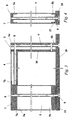
figure 1 is an axonometric view of the structure according to the invention; -
figure 2 is a side view of a modular element of the structure according to the invention; -
figures 3 and 4 are section views of a modular element of the structure according to the invention; -
figures 5, 6 and 7 are views of a part of the modular element. - With special reference to such figures, a carrying structure for furniture, especially to be employed in the kitchen furnishing industry, has been generally designated by reference numeral 1.
- Structure 1 comprises a plurality of
modular elements 2, each of which featuring a pair of uprights 3 and acrosspiece 4. Thecrosspiece 4 has its ends associated with the uprights 3 by means of the interposition of temporary fastening means. More specifically, each of themodular elements 2 comprises a front upright 5 and a rear upright 6, where the words "front" and "rear" refer, in this description and in a non-exclusive way, to the normal layout of the structure 1 after this has been positioned to furnish an interior. - As shown in
figures 5, 6 and 7 , the temporary fastening means comprise afirst joint 7, featuring a pair oflower protruding elements 7a and a pair ofrear protruding elements 7b. The particular tubular configuration, open at the ends, of the uprights 3 and thecrosspiece 4 permits the slotting in of thelower protruding elements 7a inside the opening defined at theupper end 5a of the front upright 5, and of the rear protrudingelements 7b inside the opening defined at thefront end 4a of thecrosspiece 4 respectively. - The fastening of the
upper end 5a andfront end 4a to thefirst joint 7 is done by means of threadedmeans 8 of the type commonly used, screws or the like, applied to an upper throughhole 7c and a rear throughhole 7d onfirst joint 7 respectively. - The
rear end 4b of thecrosspiece 4 is fastened to theupper end 6a of the rear upright 6 by means of respective threadedmeans 8. - Other configurations of
first joint 7, uprights 3 and therelevant crosspiece 4 are however not to be ruled out. - As shown in
figure 1 , the modular elements, suitably sized and conformed, can be associated with one another to make a hanging structure P or, alternatively, a ground structure T, both commonly used to furnish kitchens or the like. - With special, but not exclusive, reference to the ground structure T shown in
figure 1 , themodular elements 2 are associated with one another in a removable way by interposing cross connection elements 9, to delimit, belowcrosspieces 4, a compartment V for housing kitchen equipments or the like (such as, for instance, household appliances or kitchen implements). - In particular, each of the cross connection elements 9 consists of a small crosspiece with ends associated with the
front uprights 5 of twomodular elements 2 which succeed one another at the respectivefirst joints 7. - A
lower top 10 is associated by horizontal arrangement at thelower ends front uprights 5 and of therear uprights 6 respectively to define a supporting base for the kitchen implements (or other equipment) arranged inside the compartment V. - Advantageously, the
lower top 10 featuresground supporting feet 11. - Usefully, the
front uprights 5 and therear uprights 6 can comprise supporting means for anintermediate top 12, arranged horizontally inside compartment V, at a substantially middle section of the uprights. - With special reference to the outer side ends of the structure 1, the
modular elements 2 can compriseside panels 13 arranged vertically and able to laterally delimit the compartment V. - Each of the
side panels 13 is fastened, by means of the threadedmeans 8 to the front andrear uprights modular element 2. - Such outer
modular elements 2 can comprise a furtherlower crosspiece 14; in the same way as seen for thecrosspiece 4, thelower crosspiece 14 has its front end associated with asecond joint 15 arranged at thelower end 5b of the front upright 5, and the rear end associated with the rear upright 6 at thelower end 6b. Fastening of the front and rear ends and of thelower crosspiece 14 is done by means of respective threadedmeans 8. -
Further side panels 13 can be associated with themodular elements 2 arranged inside the structure 1, to define a plurality of compartments V, each one separate from the other. - Usefully, one or more
rear panels 16 can be associated with themodular elements 2, at the respectiverear uprights 6, for the rear closing of the compartment V (at the portion of the structure 1 which commonly faces onto and is adjacent to a wall of the interior to be furnished). - An
upper top 17 is associated in a removable way with themodular elements 2, resting on thecrosspieces 4 and on the small crosspieces 9, and extends horizontally along the entire ground structure T to define a supporting and/or work top, for instance, for the preparation of food. Theupper top 17 can be made in a single body or as several distinct sections positioned alongside each other. - Advantageously, to the
front uprights 5 hinging means of a door A can be associated able to open and close the compartment V, or alternatively, both thefront uprights 5 and the respectiverear uprights 6 can support straight guide means of a sliding element, for example, of a basket or a drawer type. - Similarly to what was seen above for the ground structure T, the hanging structure P comprises respective
lower tops 10,intermediate tops 12 andupper tops 17,side panels 13,rear panels 16, as well as, if necessary, hinging means and straight guide means supported by the uprights 3. - The hanging structure P can comprise a supporting column, fastened to a wall of the interior to be furnished, and means, of the traditionally used type, for fastening the
rear uprights 6 to such column. - Advantageously, the single
modular elements 2 or the entire structure 1 can be made using materials of the metal, fireproof and water-repellent type. - Practically speaking, it has been found how the invention described reaches the proposed aims, and, in particular, the fact is underlined that the presence of the modular elements which can be associated the one with the other permits obtaining an extremely versatile structure that is easily adaptable to any type of interior, both in terms of measurements and different layouts.
- The extreme modularity of the structure also permits proposing a broad range of solutions able to cater for even much differing aesthetic requirements.
- The size of the internal compartment or compartments can also be as required to satisfy specific storage capacity needs.
- It should also be noticed that once assembled, the structure is easy to clean and without the spaces usually found between the modules of traditional modular kitchens and which gather up dust or dirt that is hard to remove.
- To this must be added the fact that the manufacture of the modular elements and, if necessary, of the panels using materials of a metal, fireproof and water-repellent type, makes the structure considerably longer lasting and less liable to damage compared to modules of known type and eliminates, for example, problems tied to water infiltration and limits the effects in case of accidental fires breaking out.
- The high modularity of the structure also, in a far from negligible way, ensures easier packaging operations and permits reduced overall dimensions during transport.
- The manufacture of the elements making up the structure in materials of the metal type, together with assembly using slot-in and/or threaded fastening means permits avoiding the use of commonly used and potentially polluting resins or adhesives.
- The invention thus conceived is susceptible of numerous modifications and variations, all of which falling within the scope of the inventive concept. Furthermore all the details can be replaced with others that are technically equivalent.
- In practice, the materials used, as well as the shapes and dimensions, may be any according to requirements without because of this moving outside the protection scope of the following claims.
Claims (16)
- Carrying structure (1) for kitchen furniture or the like, comprising:a plurality of modular elements (2) each featuring at least two uprights (3), respectively a front upright (5) and a rear upright (6), and at least one crosspiece (4) associated with said two uprights (5, 6) by placing temporary fastening means (7, 7a, 7b, 8) in between, andat least one substantially continuous horizontal lower top (10) associated with the lower ends (5b, 6b) of the uprights (5, 6) of said plurality of modular elements (2),wherein said modular elements (2) are arranged at the lower ends (5b, 6b) of the respective uprights (5, 6) on and supported by said at least one substantially horizontal lower top (10) and are associated with each other in a removable way by interposing cross connection elements (9) so as to delimit, below said crosspieces (4), at least one housing compartment (V) for kitchen equipment or the like, and to support at least one substantially horizontal supporting and/or work top, andwherein each of said cross connection element comprises at least one small crosspiece (9) which is interposed between two succeeding front uprights (5) of two modular elements (2) which succeed one another on said at least one substantially horizontal lower top (10), with the ends of said small crosspiece (9) being associated with said two succeeding front uprights (5) at the respective fastening means (7,7a,7b,8) with the crosspiece (4) of the corresponding modular element (2),whereby said carrying structure (1) is adaptable to any type of interior to be furnished, as corresponding to said at least one substantially horizontal lower top (10), both in terms of measurements and different layouts,said carrying structure (1) being characterised in that said temporary fastening means (7,7a,7b,8) comprise at least one joint (7) which can be slotted in between an upper end (5a) of at least one (5) of said uprights, in particular of said front upright (5), and a front end (4a) of said crosspiece (4), said joint (7) featuring a pair of lower protruding elements (7a) and a pair of rear protruding elements (7b),wherein the uprights (3, 5, 6) and the crosspiece (4) have a tubular configuration, open at the ends, so as to permit the slotting in of the lower protruding elements (7a) of said joint (7) inside the opening defined at the upper end (5a) of the front upright (5) and the slotting in of the rear protruding elements (7b) of said joint (7) inside the opening defined at the front end (4a) of said crosspiece (4),wherein said joint (7) comprises an upper through hole (7c) and a rear through hole (7d) and the fastening of said upper end (5a) and of said front end (4a) to said joint (7) is done by means of threaded means (8) applied to said upper through hole (7c) and to said rear through hole (7d).
- Structure according to claim 1, wherein said threaded means (8) are able to fasten the upper end (5a) of said front upright (5) and the front end (4a) of said crosspiece (4) to said joint (7), and to fasten the rear end (4b) of the crosspiece (4) to the upper end (6a) of said rear upright (6).
- Structure according to claim 1, wherein the modular elements (2) arranged at the outer sides of said carrying structure (1) comprise a further lower crosspiece (14) that is associated at its front end with a further joint (15) arranged at the lower end (5b) of the front upright (5), and is associated at its rear end with the lower end (6b) of the rear upright (6) of the modular element (2).
- Structure according to one or more of the preceding claims, characterized by the fact that it comprises at least one substantially horizontal upper top (17), associated with at least one of said modular elements (2) in a removable way and resting on said crosspiece (4).
- Structure according to one or more of the preceding claims, characterized by the fact that at least one of said uprights (5, 6) comprises supporting means of at least one intermediate top (12), substantially horizontal and arranged inside said compartment (V), at a substantially middle section of said upright (5,6).
- Structure according to one or more of the preceding claims, characterized by the fact that at least one of said uprights (5, 6) comprises hinging means of at least one door able to open and close said compartment.
- Structure according to one or more of the preceding claims, characterized by the fact that at least one of said uprights comprises straight guide means of at least one sliding element along a substantially horizontal direction.
- Structure according to one or more of the preceding claims, characterized by the fact that said sliding element is of a basket, a drawer type or the like.
- Structure according to one or more of the preceding claim, characterized by the fact that at least one of said modular elements (2) comprises a side panel (13) arranged substantially vertical and associated in a removable way with at least one between said uprights (5, 6) and said crosspiece (4).
- Structure according to one or more of the preceding claims, characterized by the fact that it comprises at least one rear panel (16) associated in a removable way with at least one of said modular elements (2), by at least one of said uprights.
- Structure according to one or more of the preceding claims, characterized by the fact that said supporting and/or work top is defined by at least one among said lower top (10), said intermediate top (12) and said upper top (17).
- Structure according to one or more of the preceding claims, characterized by the fact that said modular elements (2) are made using materials of the metal type.
- Structure according to one or more of the preceding claims, characterized by the fact that said modular elements (2) are made using materials of the water-repellent type.
- Structure according to one or more of the preceding claims, characterized by the fact that said modular elements (2) are made using materials of the fireproof type.
- Structure according to one or more of the preceding claims, wherein said carrying structure exhibits at least two portions, as defined by said horizontal lower top (10) and by said modular elements (2), which are reciprocally arranged according to an angled configuration.
- Structure according to one or more of the preceding claims, wherein said at least one substantially horizontal lower top (10) features ground supporting feet (11) at positions which are different from and not aligned with those of the lower ends (5b, 6b) of said uprights (5, 6), whereby said modular elements (2) are arranged on and supported by said at least one substantially horizontal lower top (10) independently from said ground supporting feet (11).
Applications Claiming Priority (2)
| Application Number | Priority Date | Filing Date | Title |
|---|---|---|---|
| IT000057A ITMO20060057A1 (en) | 2006-02-21 | 2006-02-21 | CARRIER STRUCTURE FOR FURNITURE, PARTICULARLY FOR THE FURNISHING OF KITCHENS OR SIMILAR |
| PCT/IB2006/001759 WO2007096695A1 (en) | 2006-02-21 | 2006-06-27 | Carrying structure for furniture, especially for kitchen furniture or the like. |
Publications (2)
| Publication Number | Publication Date |
|---|---|
| EP1987258A1 EP1987258A1 (en) | 2008-11-05 |
| EP1987258B1 true EP1987258B1 (en) | 2013-03-13 |
Family
ID=37410188
Family Applications (1)
| Application Number | Title | Priority Date | Filing Date |
|---|---|---|---|
| EP06779780A Not-in-force EP1987258B1 (en) | 2006-02-21 | 2006-06-27 | Carrying structure for furniture, especially for kitchen furniture or the like |
Country Status (5)
| Country | Link |
|---|---|
| US (1) | US20090218919A1 (en) |
| EP (1) | EP1987258B1 (en) |
| CN (1) | CN101379304A (en) |
| IT (1) | ITMO20060057A1 (en) |
| WO (1) | WO2007096695A1 (en) |
Families Citing this family (2)
| Publication number | Priority date | Publication date | Assignee | Title |
|---|---|---|---|---|
| WO2020119875A1 (en) * | 2018-12-09 | 2020-06-18 | El Tonsy Husham Hassan Mohamed Hussin | Integrated smart, healthy and safe cooking oven (pressure oven). |
| US20230248142A1 (en) * | 2022-02-10 | 2023-08-10 | Scott C. Lunt | Outdoor cabinet apparatus and method |
Family Cites Families (22)
| Publication number | Priority date | Publication date | Assignee | Title |
|---|---|---|---|---|
| US1473817A (en) * | 1919-11-15 | 1923-11-13 | Kawneer Mfg Company | Metal frame and interlocking joint |
| US2466869A (en) * | 1942-02-26 | 1949-04-12 | Farley & Loetscher Mfg Company | Cabinet construction |
| GB621680A (en) * | 1945-11-14 | 1949-04-14 | Robert Cliffe | Improvements in or relating to cabinet and like furniture framework and joints |
| FR1239881A (en) * | 1958-11-12 | 1960-08-26 | Removable shelving or similar furniture | |
| US3178244A (en) * | 1961-03-31 | 1965-04-13 | Stanley Works | Modular enclosure |
| US3150903A (en) * | 1962-10-22 | 1964-09-29 | Vega Ind Inc | Frame structure for cabinets and the like |
| US3178245A (en) * | 1962-10-31 | 1965-04-13 | Kenneth S Morioka | Modular cabinet structure |
| US3297380A (en) * | 1963-03-14 | 1967-01-10 | Sel Rex Corp | Electroplating installation |
| DE1429602A1 (en) | 1964-11-17 | 1969-08-07 | Krone Kg | Universal box |
| DE1429611A1 (en) * | 1964-12-31 | 1969-05-29 | Lust Kg Ernst | closet |
| GB1336991A (en) * | 1969-12-22 | 1973-11-14 | Symons M W | Structure and method of forming such a structure |
| US3877765A (en) * | 1972-08-14 | 1975-04-15 | Mpc Corp | Furniture structure |
| FR2364354A1 (en) * | 1976-09-09 | 1978-04-07 | Beaux Dominique | Modular structure assembled without tools - has metal corner plates with pins passed through holes in structure and plates |
| US5626404A (en) * | 1988-06-10 | 1997-05-06 | Herman Miller, Inc. | Work space management system and cabinet therefor |
| FR2634259B1 (en) * | 1988-07-13 | 1990-11-09 | Girinon Rene | ASSEMBLY SYSTEM FOR PRODUCING VARIOUS OBJECTS OF THE FURNITURE TYPE IN PARTICULAR |
| US5470139A (en) * | 1994-01-24 | 1995-11-28 | Hsiao; Szu-Chang | Combined display case |
| US6152553A (en) * | 1998-05-29 | 2000-11-28 | Wunderlich; Dale N. | Modular furniture construction system |
| US20070092333A1 (en) * | 1999-11-15 | 2007-04-26 | Tom Viscount | Apparatus for securely yet removably installing an ornament onto a substantially planar surface |
| EP1159891A1 (en) | 2000-05-29 | 2001-12-05 | Swatch Ag | Modular framework for furniture and handles for transport of such furniture |
| DE202004001722U1 (en) * | 2004-02-05 | 2004-06-24 | Tzeng, Ren-Ju | Connecting structure for tubes used in furniture and rack constructions has threaded holes in connecting elements and with countersink to accommodate flange of threaded bolt in initial stage of connection |
| WO2006043898A1 (en) * | 2004-10-19 | 2006-04-27 | Technigroup Far East Pte Ltd | Modular storage system |
| WO2009076715A1 (en) * | 2007-12-17 | 2009-06-25 | Ted Turnour | Interlocking assembly system and method |
-
2006
- 2006-02-21 IT IT000057A patent/ITMO20060057A1/en unknown
- 2006-06-27 US US12/224,131 patent/US20090218919A1/en not_active Abandoned
- 2006-06-27 WO PCT/IB2006/001759 patent/WO2007096695A1/en active Application Filing
- 2006-06-27 EP EP06779780A patent/EP1987258B1/en not_active Not-in-force
- 2006-06-27 CN CNA2006800530707A patent/CN101379304A/en active Pending
Also Published As
| Publication number | Publication date |
|---|---|
| EP1987258A1 (en) | 2008-11-05 |
| ITMO20060057A1 (en) | 2007-08-22 |
| WO2007096695A1 (en) | 2007-08-30 |
| US20090218919A1 (en) | 2009-09-03 |
| CN101379304A (en) | 2009-03-04 |
Similar Documents
| Publication | Publication Date | Title |
|---|---|---|
| JPS6254002B2 (en) | ||
| US7624745B2 (en) | Drawer-type dishwasher having modular support body | |
| EP1987258B1 (en) | Carrying structure for furniture, especially for kitchen furniture or the like | |
| US20070182293A1 (en) | Universal bracket used to fix doors to cabinet pull-out elements | |
| US7959742B2 (en) | Outer support body for a drawer-type dishwasher | |
| US6000874A (en) | Furniture system, in particular a kitchen furniture system | |
| CN203970954U (en) | For the household electrical appliance of tableware | |
| US8752914B1 (en) | Dish rack mounted in kitchen cabinet | |
| WO2006038244A1 (en) | Universal bracket used to fix doors to cabinet pull-out elements | |
| WO2017178161A1 (en) | Mounting device and domestic appliance | |
| US11980287B1 (en) | Backward-angled dual-frame cabinet system | |
| CN210433265U (en) | Combined tableware mat | |
| JP7415586B2 (en) | kitchen unit | |
| JP6989866B1 (en) | Face-to-face storage box Storage case installed on the kitchen. | |
| CN210947024U (en) | Water tank and cleaning equipment | |
| DE102014203961B4 (en) | Board, washing container, dishwasher and process | |
| CN207383912U (en) | A kind of multifunctional unit kitchen cabinet | |
| EP3318806A1 (en) | Protective wall for a cooking hob | |
| DE202008004255U1 (en) | Kitchen furniture item | |
| DE19742220A1 (en) | Storage system for kitchen | |
| US2306106A (en) | Kitchen cabinet | |
| NO20210051A1 (en) | ||
| JP3198737U (en) | Multi dining storage furniture | |
| DE102021203013A1 (en) | Extendable connecting rail and household appliance | |
| WO2002053007A1 (en) | Dishwasher |
Legal Events
| Date | Code | Title | Description |
|---|---|---|---|
| PUAI | Public reference made under article 153(3) epc to a published international application that has entered the european phase |
Free format text: ORIGINAL CODE: 0009012 |
|
| 17P | Request for examination filed |
Effective date: 20080911 |
|
| AK | Designated contracting states |
Kind code of ref document: A1 Designated state(s): AT BE BG CH CY CZ DE DK EE ES FI FR GB GR HU IE IS IT LI LT LU LV MC NL PL PT RO SE SI SK TR |
|
| 17Q | First examination report despatched |
Effective date: 20101001 |
|
| DAX | Request for extension of the european patent (deleted) | ||
| REG | Reference to a national code |
Ref country code: DE Ref legal event code: R079 Ref document number: 602006035073 Country of ref document: DE Free format text: PREVIOUS MAIN CLASS: F16B0012020000 Ipc: A63C0005000000 |
|
| GRAP | Despatch of communication of intention to grant a patent |
Free format text: ORIGINAL CODE: EPIDOSNIGR1 |
|
| RIC1 | Information provided on ipc code assigned before grant |
Ipc: A63C 5/04 20060101ALI20120917BHEP Ipc: A63C 5/00 20060101AFI20120917BHEP |
|
| GRAS | Grant fee paid |
Free format text: ORIGINAL CODE: EPIDOSNIGR3 |
|
| GRAA | (expected) grant |
Free format text: ORIGINAL CODE: 0009210 |
|
| AK | Designated contracting states |
Kind code of ref document: B1 Designated state(s): AT BE BG CH CY CZ DE DK EE ES FI FR GB GR HU IE IS IT LI LT LU LV MC NL PL PT RO SE SI SK TR |
|
| REG | Reference to a national code |
Ref country code: GB Ref legal event code: FG4D |
|
| REG | Reference to a national code |
Ref country code: CH Ref legal event code: EP Ref country code: AT Ref legal event code: REF Ref document number: 600431 Country of ref document: AT Kind code of ref document: T Effective date: 20130315 |
|
| REG | Reference to a national code |
Ref country code: IE Ref legal event code: FG4D |
|
| REG | Reference to a national code |
Ref country code: DE Ref legal event code: R096 Ref document number: 602006035073 Country of ref document: DE Effective date: 20130508 |
|
| PG25 | Lapsed in a contracting state [announced via postgrant information from national office to epo] |
Ref country code: BG Free format text: LAPSE BECAUSE OF FAILURE TO SUBMIT A TRANSLATION OF THE DESCRIPTION OR TO PAY THE FEE WITHIN THE PRESCRIBED TIME-LIMIT Effective date: 20130613 Ref country code: ES Free format text: LAPSE BECAUSE OF FAILURE TO SUBMIT A TRANSLATION OF THE DESCRIPTION OR TO PAY THE FEE WITHIN THE PRESCRIBED TIME-LIMIT Effective date: 20130624 Ref country code: LT Free format text: LAPSE BECAUSE OF FAILURE TO SUBMIT A TRANSLATION OF THE DESCRIPTION OR TO PAY THE FEE WITHIN THE PRESCRIBED TIME-LIMIT Effective date: 20130313 Ref country code: SE Free format text: LAPSE BECAUSE OF FAILURE TO SUBMIT A TRANSLATION OF THE DESCRIPTION OR TO PAY THE FEE WITHIN THE PRESCRIBED TIME-LIMIT Effective date: 20130313 |
|
| REG | Reference to a national code |
Ref country code: AT Ref legal event code: MK05 Ref document number: 600431 Country of ref document: AT Kind code of ref document: T Effective date: 20130313 |
|
| REG | Reference to a national code |
Ref country code: NL Ref legal event code: VDEP Effective date: 20130313 |
|
| REG | Reference to a national code |
Ref country code: LT Ref legal event code: MG4D |
|
| PG25 | Lapsed in a contracting state [announced via postgrant information from national office to epo] |
Ref country code: GR Free format text: LAPSE BECAUSE OF FAILURE TO SUBMIT A TRANSLATION OF THE DESCRIPTION OR TO PAY THE FEE WITHIN THE PRESCRIBED TIME-LIMIT Effective date: 20130614 Ref country code: SI Free format text: LAPSE BECAUSE OF FAILURE TO SUBMIT A TRANSLATION OF THE DESCRIPTION OR TO PAY THE FEE WITHIN THE PRESCRIBED TIME-LIMIT Effective date: 20130313 Ref country code: FI Free format text: LAPSE BECAUSE OF FAILURE TO SUBMIT A TRANSLATION OF THE DESCRIPTION OR TO PAY THE FEE WITHIN THE PRESCRIBED TIME-LIMIT Effective date: 20130313 Ref country code: LV Free format text: LAPSE BECAUSE OF FAILURE TO SUBMIT A TRANSLATION OF THE DESCRIPTION OR TO PAY THE FEE WITHIN THE PRESCRIBED TIME-LIMIT Effective date: 20130313 |
|
| PG25 | Lapsed in a contracting state [announced via postgrant information from national office to epo] |
Ref country code: BE Free format text: LAPSE BECAUSE OF FAILURE TO SUBMIT A TRANSLATION OF THE DESCRIPTION OR TO PAY THE FEE WITHIN THE PRESCRIBED TIME-LIMIT Effective date: 20130313 |
|
| PG25 | Lapsed in a contracting state [announced via postgrant information from national office to epo] |
Ref country code: NL Free format text: LAPSE BECAUSE OF FAILURE TO SUBMIT A TRANSLATION OF THE DESCRIPTION OR TO PAY THE FEE WITHIN THE PRESCRIBED TIME-LIMIT Effective date: 20130313 Ref country code: IS Free format text: LAPSE BECAUSE OF FAILURE TO SUBMIT A TRANSLATION OF THE DESCRIPTION OR TO PAY THE FEE WITHIN THE PRESCRIBED TIME-LIMIT Effective date: 20130713 Ref country code: PT Free format text: LAPSE BECAUSE OF FAILURE TO SUBMIT A TRANSLATION OF THE DESCRIPTION OR TO PAY THE FEE WITHIN THE PRESCRIBED TIME-LIMIT Effective date: 20130715 Ref country code: EE Free format text: LAPSE BECAUSE OF FAILURE TO SUBMIT A TRANSLATION OF THE DESCRIPTION OR TO PAY THE FEE WITHIN THE PRESCRIBED TIME-LIMIT Effective date: 20130313 Ref country code: AT Free format text: LAPSE BECAUSE OF FAILURE TO SUBMIT A TRANSLATION OF THE DESCRIPTION OR TO PAY THE FEE WITHIN THE PRESCRIBED TIME-LIMIT Effective date: 20130313 Ref country code: CZ Free format text: LAPSE BECAUSE OF FAILURE TO SUBMIT A TRANSLATION OF THE DESCRIPTION OR TO PAY THE FEE WITHIN THE PRESCRIBED TIME-LIMIT Effective date: 20130313 Ref country code: RO Free format text: LAPSE BECAUSE OF FAILURE TO SUBMIT A TRANSLATION OF THE DESCRIPTION OR TO PAY THE FEE WITHIN THE PRESCRIBED TIME-LIMIT Effective date: 20130313 Ref country code: SK Free format text: LAPSE BECAUSE OF FAILURE TO SUBMIT A TRANSLATION OF THE DESCRIPTION OR TO PAY THE FEE WITHIN THE PRESCRIBED TIME-LIMIT Effective date: 20130313 |
|
| PG25 | Lapsed in a contracting state [announced via postgrant information from national office to epo] |
Ref country code: PL Free format text: LAPSE BECAUSE OF FAILURE TO SUBMIT A TRANSLATION OF THE DESCRIPTION OR TO PAY THE FEE WITHIN THE PRESCRIBED TIME-LIMIT Effective date: 20130313 Ref country code: CY Free format text: LAPSE BECAUSE OF FAILURE TO SUBMIT A TRANSLATION OF THE DESCRIPTION OR TO PAY THE FEE WITHIN THE PRESCRIBED TIME-LIMIT Effective date: 20130313 |
|
| PLBE | No opposition filed within time limit |
Free format text: ORIGINAL CODE: 0009261 |
|
| STAA | Information on the status of an ep patent application or granted ep patent |
Free format text: STATUS: NO OPPOSITION FILED WITHIN TIME LIMIT |
|
| PG25 | Lapsed in a contracting state [announced via postgrant information from national office to epo] |
Ref country code: DK Free format text: LAPSE BECAUSE OF FAILURE TO SUBMIT A TRANSLATION OF THE DESCRIPTION OR TO PAY THE FEE WITHIN THE PRESCRIBED TIME-LIMIT Effective date: 20130313 Ref country code: MC Free format text: LAPSE BECAUSE OF FAILURE TO SUBMIT A TRANSLATION OF THE DESCRIPTION OR TO PAY THE FEE WITHIN THE PRESCRIBED TIME-LIMIT Effective date: 20130313 |
|
| REG | Reference to a national code |
Ref country code: CH Ref legal event code: PL |
|
| 26N | No opposition filed |
Effective date: 20131216 |
|
| GBPC | Gb: european patent ceased through non-payment of renewal fee |
Effective date: 20130627 |
|
| REG | Reference to a national code |
Ref country code: IE Ref legal event code: MM4A |
|
| REG | Reference to a national code |
Ref country code: DE Ref legal event code: R097 Ref document number: 602006035073 Country of ref document: DE Effective date: 20131216 Ref country code: DE Ref legal event code: R119 Ref document number: 602006035073 Country of ref document: DE Effective date: 20140101 |
|
| REG | Reference to a national code |
Ref country code: FR Ref legal event code: ST Effective date: 20140228 |
|
| PG25 | Lapsed in a contracting state [announced via postgrant information from national office to epo] |
Ref country code: CH Free format text: LAPSE BECAUSE OF NON-PAYMENT OF DUE FEES Effective date: 20130630 Ref country code: GB Free format text: LAPSE BECAUSE OF NON-PAYMENT OF DUE FEES Effective date: 20130627 Ref country code: IE Free format text: LAPSE BECAUSE OF NON-PAYMENT OF DUE FEES Effective date: 20130627 Ref country code: LI Free format text: LAPSE BECAUSE OF NON-PAYMENT OF DUE FEES Effective date: 20130630 Ref country code: DE Free format text: LAPSE BECAUSE OF NON-PAYMENT OF DUE FEES Effective date: 20140101 |
|
| PG25 | Lapsed in a contracting state [announced via postgrant information from national office to epo] |
Ref country code: FR Free format text: LAPSE BECAUSE OF NON-PAYMENT OF DUE FEES Effective date: 20130701 |
|
| PG25 | Lapsed in a contracting state [announced via postgrant information from national office to epo] |
Ref country code: TR Free format text: LAPSE BECAUSE OF FAILURE TO SUBMIT A TRANSLATION OF THE DESCRIPTION OR TO PAY THE FEE WITHIN THE PRESCRIBED TIME-LIMIT Effective date: 20130313 |
|
| PG25 | Lapsed in a contracting state [announced via postgrant information from national office to epo] |
Ref country code: HU Free format text: LAPSE BECAUSE OF FAILURE TO SUBMIT A TRANSLATION OF THE DESCRIPTION OR TO PAY THE FEE WITHIN THE PRESCRIBED TIME-LIMIT; INVALID AB INITIO Effective date: 20060627 Ref country code: LU Free format text: LAPSE BECAUSE OF NON-PAYMENT OF DUE FEES Effective date: 20130627 |
|
| PGFP | Annual fee paid to national office [announced via postgrant information from national office to epo] |
Ref country code: IT Payment date: 20150624 Year of fee payment: 10 |
|
| PG25 | Lapsed in a contracting state [announced via postgrant information from national office to epo] |
Ref country code: IT Free format text: LAPSE BECAUSE OF NON-PAYMENT OF DUE FEES Effective date: 20160627 |