EP1986853B1 - Supporting frame for a printing screen - Google Patents
Supporting frame for a printing screen Download PDFInfo
- Publication number
- EP1986853B1 EP1986853B1 EP07712684A EP07712684A EP1986853B1 EP 1986853 B1 EP1986853 B1 EP 1986853B1 EP 07712684 A EP07712684 A EP 07712684A EP 07712684 A EP07712684 A EP 07712684A EP 1986853 B1 EP1986853 B1 EP 1986853B1
- Authority
- EP
- European Patent Office
- Prior art keywords
- printing screen
- engagement
- interface
- apertures
- interface units
- Prior art date
- Legal status (The legal status is an assumption and is not a legal conclusion. Google has not performed a legal analysis and makes no representation as to the accuracy of the status listed.)
- Active
Links
Images



Classifications
-
- B—PERFORMING OPERATIONS; TRANSPORTING
- B41—PRINTING; LINING MACHINES; TYPEWRITERS; STAMPS
- B41F—PRINTING MACHINES OR PRESSES
- B41F15/00—Screen printers
-
- B—PERFORMING OPERATIONS; TRANSPORTING
- B41—PRINTING; LINING MACHINES; TYPEWRITERS; STAMPS
- B41F—PRINTING MACHINES OR PRESSES
- B41F15/00—Screen printers
- B41F15/14—Details
- B41F15/34—Screens, Frames; Holders therefor
- B41F15/36—Screens, Frames; Holders therefor flat
-
- B—PERFORMING OPERATIONS; TRANSPORTING
- B41—PRINTING; LINING MACHINES; TYPEWRITERS; STAMPS
- B41M—PRINTING, DUPLICATING, MARKING, OR COPYING PROCESSES; COLOUR PRINTING
- B41M1/00—Inking and printing with a printer's forme
- B41M1/12—Stencil printing; Silk-screen printing
-
- H—ELECTRICITY
- H05—ELECTRIC TECHNIQUES NOT OTHERWISE PROVIDED FOR
- H05K—PRINTED CIRCUITS; CASINGS OR CONSTRUCTIONAL DETAILS OF ELECTRIC APPARATUS; MANUFACTURE OF ASSEMBLAGES OF ELECTRICAL COMPONENTS
- H05K3/00—Apparatus or processes for manufacturing printed circuits
- H05K3/10—Apparatus or processes for manufacturing printed circuits in which conductive material is applied to the insulating support in such a manner as to form the desired conductive pattern
- H05K3/12—Apparatus or processes for manufacturing printed circuits in which conductive material is applied to the insulating support in such a manner as to form the desired conductive pattern using thick film techniques, e.g. printing techniques to apply the conductive material or similar techniques for applying conductive paste or ink patterns
- H05K3/1216—Apparatus or processes for manufacturing printed circuits in which conductive material is applied to the insulating support in such a manner as to form the desired conductive pattern using thick film techniques, e.g. printing techniques to apply the conductive material or similar techniques for applying conductive paste or ink patterns by screen printing or stencil printing
- H05K3/1225—Screens or stencils; Holders therefor
-
- H—ELECTRICITY
- H05—ELECTRIC TECHNIQUES NOT OTHERWISE PROVIDED FOR
- H05K—PRINTED CIRCUITS; CASINGS OR CONSTRUCTIONAL DETAILS OF ELECTRIC APPARATUS; MANUFACTURE OF ASSEMBLAGES OF ELECTRICAL COMPONENTS
- H05K2203/00—Indexing scheme relating to apparatus or processes for manufacturing printed circuits covered by H05K3/00
- H05K2203/01—Tools for processing; Objects used during processing
- H05K2203/0147—Carriers and holders
- H05K2203/0169—Using a temporary frame during processing
Definitions
- the present invention relates to printing screens, often alternatively referred to as stencils or masks, for use in the screen printing of workpieces, typically electronic substrates, such as circuit boards and components, frames therefor, and printing screen units.
- printing screens have been mounted in large rectangular frames by a flexible, perforate sheet, typically a woven mesh of polypropylene or stainless steel strands, which acts to tension the printing screen.
- the mounting system does exhibit a number of drawbacks, notably in not allowing the printing screen to be detached from the frame without permanently damaging the perforate sheet, which requires the printing screens to be maintained in the mounted state, and thus requires a large storage facility for storing a large number of mounted printing screens.
- the printing screen which comprises a thin, stiff metal sheet, typically of stainless steel, includes a plurality of fixing apertures at the opposite edges thereof by which the printing screen is mounted to a frame by mechanical tensioning mechanisms which engage the fixing apertures in the printing screen and act to tension the printing screen, with the tensioning force typically being provided by hydraulic, pneumatic or spring means.
- this mounting system does suffer from a number of drawbacks.
- the printing screens are very thin, typically having a thickness of from 0.1 to 0.25 mm, the edges thereof are razor sharp, which can lead to personal injury to a user if not handled with the utmost care.
- a mounting system which enables a printing screen to be demounted after use, and also, in utilizing an attachment frame, typically in the form of extrusions, shields the edges of the printing screen and thus prevents the possibility of personal injury to a user as could be caused by the sharp edges of a printing screen.
- WO-A-2003/015486 discloses a stencil which includes mounting apertures at the edges thereof and stress-relief zones located between the mounting apertures at the respective ones of the edges of the stencil and a central stencilling region.
- the present invention provides a supporting frame for supporting a printing screen, comprising a sheet, at least sections of at least one pair of opposite edges of which include one of engagement apertures or engagement projections, preferably at least ones of the one of engagement apertures or engagement projections are circular in shape, the supporting frame comprising: at least one pair of interface units which are attachable to the at least one pair of opposite edges of the printing screen, wherein the interface units each comprise at least one coupling element which includes the other of engagement apertures or engagement projections, preferably at least ones of the other of engagement apertures or engagement projections are circular in shape, for inter-engaging with the one of engagement apertures or engagement projections at a respective one of the opposite edges of the printing screen, and an interface member for engagement to a tensioning mechanism which includes a coupling section which comprises first and second body parts which together define a coupling slot therebetween which receives the at least one coupling element and the respective edge of the printing screen and captively holds the at least one coupling element therein, wherein the coupling slot and the at least
- the at least one pair of opposite edges of the printing screen include engagement apertures and the at least one coupling element of each interface unit includes engagement projections for engaging the engagement apertures in the edges of the printing screen.
- At least sections of the at least one pair of opposite edges of the printing screen include a plurality of rows of one of engagement apertures or engagement projections which are disposed one inwardly of the other relative to the respective edge of the printing screen and the coupling elements of the interface units include a plurality of rows of the other of engagement apertures or engagement projections which correspond to the rows of the one of engagement apertures or engagement projections in the respective edges of the printing screen.
- the rows of the one of engagement apertures or engagement projections in each edge of the printing screen are located in offset relation along a length of the respective edge of the printing screen and the rows of the other of engagement apertures or engagement projections on each coupling element are located in a counterpart offset relation.
- the at least one coupling element is an element separate to the printing screen.
- the coupling slot comprises a support slot part which supports the at least one coupling element and includes an engagement surface at an inner edge thereof, against which the at least one coupling element is engaged when a tensioning force is applied to the interface member.
- the coupling slot comprises a recessed slot part which includes at least one recess into which extend the distal ends of the engagement projections, such as to retain the printing screen captively thereon.
- the support slot part and the recessed slot part are disposed in opposed relation.
- the interface member includes an engagement section which is disposed outwardly of the coupling slot and provides for engagement to a tensioning mechanism.
- the supporting frame includes: one pair of interface units which are in use attached to one pair of opposite edges of the printing screen.
- the printing screen has two pairs of opposite edges, at least section of which include the one of engagement apertures or engagement projections, and comprises: first and second pairs of interface units which are in use attached to the respective pairs of opposite edges of the printing screen.
- the supporting frame further comprises: corner pieces which are disposed adjacent ends of the interface units.
- corner pieces couple adjacent ends of the interface units.
- corner pieces are parts separate to the interface units.
- corner pieces are integral parts of at least ones of the interface units.
- the interface members of one of the pairs of interface units are longer than the interface members of the other of the pairs of interface units, such that the ends of the interface members of the one of the pairs of interface units overlap the adjacent ends of the interface members of the other of the pairs of interface units.
- corner pieces are parts separate to the interface units and are attached to the ends of the interface members of the one of the pairs of interface units.
- corner pieces are defined by the ends of the interface members of the one of the pairs of interface units.
- each coupling element comprises an elongate strip which includes the other of the engagement apertures or engagement projections thereon.
- At least ones of the interface units comprise a plurality of coupling elements.
- the coupling elements are disposed in end-to-end relation along a length of the interface member.
- the coupling elements are disposed in spaced relation along a length of the interface member.
- the supporting frame is configured to provide for relative movement of the interface members on being tensioned by a tensioning mechanism.
- the present invention provides a printing screen unit, comprising: a printing screen, comprising a sheet, at least sections of at least one pair of opposite edges of which include one of engagement apertures or engagement projections; and the above-described supporting frame.
- the printing screen includes a pattern of printing apertures which define a pattern of deposits to be printed thereby.
- the printing screen is a blank and includes no printing apertures therein.
- the printing screen comprises a metal sheet.
- the printing screen comprises a plastics sheet.
- the present invention provides a method of fitting a supporting frame to a printing screen, comprising the steps of: providing a printing screen, comprising a sheet having two pairs of opposite edges, at least sections of which include a plurality of rows of one of engagement apertures or engagement projections, preferably engagement apertures, which are disposed one inwardly of the other relative to the respective edge of the sheet and located in offset relation along a length of the respective edge of the sheet, and preferably at least ones of the one of engagement apertures or engagement projections are circular in shape; and fitting at least one coupling element, which includes the other of engagement apertures or engagement projections, preferably engagement projections, to each edge of the sheet by inter-engaging the other of engagement apertures or engagement projections in the one of engagement apertures or engagement projections in the sheet, and preferably at least ones of the other of engagement apertures or engagement projections are circular in shape.
- the present invention provides an improved printing screen unit which is compatible with existing support frame systems, with the interface members protecting edges of the printing screen from damage during handling and mounting, thereby increasing the life of the printing screen, and the sharp edges of the printing screen being enclosed, making the printing screen safer to handle.
- the attachment of a printing screen to interface members further simplifies the manufacture of the printing screen unit as a whole, in obviating the need for an adhesive bond.
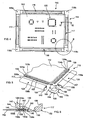
- Figures 1 to 3 illustrate a prior art printing screen unit 10, as disclosed in WO-A-2003/093012 .
- the printing screen unit 10 comprises a printing screen 12, in this embodiment of rectangular shape, and a supporting frame 14 for supporting the printing screen 12, which comprises first and second pairs of interface members 16, 16, 17, 17 which are attached to the respective pairs of opposite edges of the printing screen 12 and first to fourth corner pieces 18a-d which couple the respective ones of the interface members 16, 16, 17,17.
- the printing screen 12 includes a pattern of printing apertures 20 which define the pattern of deposits to be printed.
- the pattern of printing apertures 20 are typically formed by laser cutting or etching.
- the printing screen 12 typically comprises a sheet of a metal, such as stainless steel, or a plastic.
- edges of the printing screen 12 to which tensioning mechanisms are attached each comprise a plurality of spaced projections 22 along the length thereof which define a castellated structure, and are folded to define attachment elements 24.
- the edges of the printing screen 12 are each folded along a line intersecting the projections 22, such that the projections 22 define a hook element and the attachment elements 24, as defined thereby, enclose an acute angle with the main body of the printing screen 12.
- the interface members 16, 16, 17, 17 each include an attachment section 26 which defines an attachment slot 32 which extends along the length thereof and in which a respective one of the attachment elements 24 of the printing screen 12 is located.
- the interface members 16, 16, 17, 17 each further include an engagement section 40 which, relative to the printing screen 12, is disposed outwardly of the attachment section 26 and provides for engagement to a tensioning mechanism.
- the engagement section 40 includes an inwardly-facing engagement surface 42 which extends along the length of the respective interface member 16, 16, 17, 17 and defines a hook arrangement which provides for captive engagement with a tensioning mechanism.
- the interface members 16, 16, 17, 17 each further include a recess 44, in this embodiment of substantially rectangular section, which extends to the distal ends thereof for receiving the tongue elements 46, 48 of respective corner pieces 18a-d, as will be described in more detail hereinbelow.
- the corner members 18a-d each include first and second tongue elements 46, 48, which extend in orthogonal directions, for fitting in respective ones of the recesses 44 in the distal ends of the adjacent interface members 16, 16, 17, 17.
- the tongue elements 46, 48 of the corner members 18a-d are configured such as to be a tight fit in the recesses 44 in the distal ends of interface members 16, 16, 17, 17, but such as to allow for movement of the tongue elements 46, 48 in the respective recesses 44 in the direction of a tension as applied to the printing screen 12.
- the interface members 16, 16, 17, 17 present a substantially rigid frame when handled, but allow for relative movement of respective opposite pairs of the interface members 16, 16, 17, 17 on being tensioned by tensioning mechanisms. Also, in allowing for relative movement of the interface members 16, 16, 17, 17, 17, design tolerances can be accommodated in order to provide for uniform tensioning of the printing screen 12.
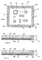
- Figures 4 to 6 illustrate a printing screen unit 110 in accordance with a first embodiment of the present invention.
- the printing screen unit 110 comprises a printing screen 112, in this embodiment of rectangular shape, and a supporting frame 114 for supporting the printing screen 112, which comprises first and second pairs of interface units 116, 116, 117, 117 which are attached to the respective pairs of opposite edges of the printing screen 112 and first to fourth corner pieces 118a-d which couple the respective ones of the interface units 116, 116, 117, 117.
- the printing screen 112 includes a pattern of printing apertures 120 which define the pattern of deposit to be printed.
- the pattern of printing apertures 120 can be formed, for example, by laser cutting or etching, as is well known in the art.
- the printing screen 112 comprises a sheet of a metal, such as stainless steel, or a plastic.
- edges of the printing screen 112 to which tensioning mechanisms are attached each comprise a plurality of engagement apertures 124 along the length thereof which define an apertured engagement structure, which is engaged by at least one coupling element 130 of a respective one of the interface units 116, 116, 117, 117, such as to couple the respective edge of the printing screen 112 to the respective one of the interface units 116, 116, 117, 117, as will be described in more detail hereinbelow.
- engagement apertures 124 are circular in shape.
- the engagement apertures 124 could, however, have any shape, for, example, square, triangular, teardrop or elongate.
- edges of the printing screen 112 each include first and second rows of engagement apertures 124a, b, which are disposed one inwardly of the other and are located in offset relation along the length of the respective edge of the printing screen 112.
- the engagement apertures 124 are formed by etching (chemical milling). In other embodiments the engagement apertures 124 could be formed using a press tool or laser. In further embodiments the engagement apertures 124 could be formed by electro-discharge machining (EDM) or water jet milling, which fabrication techniques would allow several printing screens 112 to be fabricated simultaneously. In still another embodiment the printing screen 112 could be formed by electroforming, and the engagement apertures 124 would be formed when forming the printing screen 112.
- EDM electro-discharge machining
- water jet milling which fabrication techniques would allow several printing screens 112 to be fabricated simultaneously.
- the printing screen 112 could be formed by electroforming, and the engagement apertures 124 would be formed when forming the printing screen 112.
- the engagement apertures 124 can be formed simultaneously with the pattern of printing apertures 120.
- the interface units 116, 116, 117, 117 each comprise an interface member 126 which provides for engagement to a tensioning mechanism, in this embodiment an elongate member which extends along the length of the respective edge of the printing screen 112, and at least one coupling element 130 which couples the interface member 126 to the respective edge of the printing screen 112.
- the interface member 126 includes a coupling section 136 which comprises a first, lower body part 138 and a second, upper body part 140, which together define a coupling slot 142 which extends along the length thereof and in which the at least one coupling element 130 and a respective one of the edges of the printing screen 112 are located, such that the respective edge of the printing screen 112 is held captive in the coupling section 136 by the at least one coupling element 130.
- the coupling slot 142 comprises a first, support slot part 144, here including a flat supporting section, which supports the at least one coupling element 130 and includes an engagement surface 146 at an inner edge thereof, against which the at least one coupling element 130 is engage when a tensioning force is applied to the interface member 126.
- the coupling slot 142 further comprises a second slot part 148 which includes at least one recess 150, here as defined by first and second parallel slots 150a, b, which are in registration with the first and second rows of engagement apertures 124a, b in each of the edges of the printing screen 112.
- the interface member 126 further includes an engagement section 152 which, relative to the printing screen 112, is disposed outwardly of the coupling section 136 and provides for engagement to a tensioning mechanism.
- the engagement section 152 includes an inwardly-facing engagement surface 154, in this embodiment defined by a continuous surface, which extends along the length of the interface member 126.
- the engagement surface 154 is outwardly inclined from the free edge thereof relative to the printing screen 112, such as to define a hook arrangement which provides for captive engagement with a tensioning mechanism.
- the engagement section 152 in being defined by a continuous surface, allows for fabrication by a wide variety of manufacturing techniques, such as machining, routing and extrusion.
- the interface member 126 further includes recesses 156, in this embodiment of substantially rectangular section, at the distal ends thereof for receiving the tongue elements 166, 170 of respective corner pieces 118a-d, as will be described in more detail hereinbelow.
- the coupling elements 130 each comprise an elongate body 157, here in the form of an elongate bar or strip of rectangular section, which is configured to fit in the support slot part 144 of the coupling slot 142 in a respective one of the interface members 126, and a plurality of engagement projections 158, here in the form of projecting studs, along the length thereof, which define a projecting engagement structure and are configured to engage the counterpart engagement apertures 124 in a respective one of the edges of the printing screen 112, as described hereinabove.
- the engagement projections 158 are circular in shape, and have a shape and configuration such as to be a close fit in the counterpart engagement apertures 124 in the printing screen 112.
- the engagement projections 158 could, however, have any shave, for, example, square, triangular, teardrop or elongate, in the same manner as the engagement apertures 124 in the printing screen 112.
- the length of at least ones of the engagement projections 158 is such that the distal ends of those engagement projections 158 extend into the at least one recess 150 in the second slot part 148 of the coupling slot 142 of the respective interface member 126 when the at least one coupling element 130 is fitted in the first slot part 144 of the coupling slot 142 of the respective interface member 126.
- the coupling elements 130 each include first and second rows of engagement projections 158a, b, which are disposed one inwardly of the other and are located in offset relation along the length of the coupling element 130.
- the interface units 116, 116, 117, 117 each include a single coupling element 130 which extends along the length of the respective interface member 126, or at least substantially the entire length thereof.
- the interface units 116, 116, 117, 117 could each include a plurality of coupling elements 130 which together extend along the length of the respective interface member 126, or at least substantially the entire length thereof.
- the ends of the adjacent coupling elements 130 could be disposed in juxtaposed, end-to-end relation.
- the ends of the adjacent coupling elements 130 could be spaced one from the other.
- corner pieces 118a-d each comprise first and second coupling members 159, 160, which lock together to define the respective corner pieces 118a-d.
- the first coupling member 159 comprises a body element 162 which includes a slot 164, here of the same rectangular section as the recesses 156 in the distal ends of the interface members 126, which extends in a first direction therethrough, and a tongue element 166 for fitting in a respective one of the recesses 156 in the distal ends of the interface members 126 which extends from the body element 162 in a second direction orthogonal to the first direction of the slot 164 therein.
- the second coupling member 160 comprises a body element 168, and a tongue element 170 for fitting in an adjacent one of the recesses 156 in the distal ends of the interface members 126 which extends from the body element 168.
- the body element 168 of the second coupling member 160 is configured to be a tight, snap-fit in the slot 164 in the body element 162 of the first coupling member 159 such that, when inserted therein, the tongue elements 166, 170 of the coupling members 159, 160 are locked in a coupling configuration.
- the coupling members 159, 160 could be bonded together.
- the coupling members 159, 160 allow for the in situ assembly of the last of the corner pieces 118a-d to be fitted, in enabling the tongue elements 166, 170 of the respective pair of the coupling members 159, 160 to be inserted into respective recesses 156 in the distal ends of the interface members 126 in assembling the last corner piece 118a-d.
- three of the corner pieces 118a-d can be pre-assembled and need not be assembled in situ. Indeed, in one embodiment three of the corner pieces 118a-d can be fabricated as an integral unit, typically as a moulding or casting.
- the tongue elements 166, 170 of the coupling members 159, 160 are configured such as to be a tight fit in the recesses 156 in the distal ends of the interface members 126, but such as to allow for movement of the tongue elements 166, 170 in the respective recesses 156 in the direction of a tension as applied to the printing screen 112.
- the interface members 126 present a substantially rigid frame when handled, but allow for relative movement of respective opposite pairs of the interface members 126 on being tensioned by tensioning mechanisms. In allowing for relative movement of the interface members 126, design tolerances can be accommodated in order to provide for uniform tensioning of the printing screen 112.
- the interface units 116, 116, 117, 117 are fitted to the respective edges of the printing screen 112, and the ends of the interface units 116, 116, 117, 117 are coupled by the corner pieces 118a-d.
- the at least one coupling element 130 of the interface unit 116 116, 117, 117 is fitted to one edge of the printing screen 112 by inserting the engagement projections 157 of the at least one coupling element 130 into the counterpart engagement apertures 124 in the respective edge of the printing screen 112, and then sliding the at least one coupling element 130 and the edge of the printing screen 112 into the coupling slot 142 of the respective interface member 126. With the at least one coupling element 130 and the edge of the printing screen 112 so inserted into the interface member 126, the edge of the printing screen 112 is then held captive to the interface member 126.
- Figures 7 and 8 illustrate a printing screen unit in accordance with a second embodiment of the present invention.
- the printing screen unit 110 of this embodiment is quite similar to the printing screen unit 110 of the above-described first embodiment, and thus, in order to avoid unnecessary duplication of description, only the differences will be described in detail, with like parts being designated by like reference signs.
- the printing screen unit 110 of this embodiment differs from the printing screen unit 110 of the above-described first embodiment in the configuration of the interface units 116, 116, 117, 117 and the corner pieces 118a-d.
- one of the opposite pairs of the interface units 116, 116 are longer than the other of the opposite pairs of interface units 117, 117, such as at least partially to overlap the adjacent ends of the opposite pair of interface units 117, 117, and the corner pieces 118a-d are defined by stop elements which are disposed at the ends of the one pair of interface units 116, 116.
- the one pair of interface units 116, 116 have a length which is substantially the same as the respective edges of the printing screen 112, but, as illustrated in Figure 8 , the interface members 126 of the one pair of interface units 116, 116 are marginally longer than the at least one coupling elements 130 thereof and the respective edges of the printing screen 112, in order to accommodate stretching of the printing screen 112 when tensioned.
- the one pair of interface units 116, 116 act to trap the other pair of interface units 117, 117, and prevent the same from sliding from the respective edges of the printing screen 112, and the one pair of interface units 116, 116 are prevented from sliding from the printing screen 112 by the corner pieces 118a-d.
- corner pieces 118a-d comprise end caps which are attached to the respective ends of the one pair of interface units 116, 116.
- the corner pieces 118a-d can be formed of a metal or a synthetic material.
- corner pieces 118a-d are fixedly coupled to the ends of the interface units 116, 116, here by bonding.
- the corner pieces 118a-d could be fixed by pins or threaded screws.
- corner pieces 118a-d could comprise end caps which are attached to the respective ends of the other pair of interface units 117, 117.
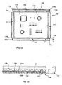
- Figures 9 and 10 illustrate a printing screen unit in accordance with a third embodiment of the present invention.
- the printing screen unit 110 of this embodiment is quite similar to the printing screen unit 110 of the above-described first embodiment, and thus, in order to avoid unnecessary duplication of description, only the differences will be described in detail, with like parts being designated by like preference signs.
- the printing screen unit 110 of this embodiment differs from the printing screen unit 110 of the above-described frst embodiment in the configuration of the interface units 116, 116, 117, 117 and the corner pieces 118a-d.
- one of the opposite pairs of the interface units 116, 116 are longer than the other of the opposite pairs of interface units 117, 117, such as at least partially to overlap the adjacent ends of the opposite pair of interface units 117, 117, and the corner pieces 118a-d are defined by stop elements which are disposed at the ends of the one pair of interface units 116, 116.
- the one pair of interface units 116, 116 that is, the interface member 126 and the at least one coupling element 130 thereof, have a length which is longer than the respective edges of the printing screen 112.
- the at least one coupling elements 130 are marginally shorter than the interface members 126 of the one pair of interface units 116, 116, in order to accommodate stretching of the printing screen 112 when tensioned.
- the one pair of interface units 116, 116 act to trap the other pair of interface units 117, 117, and prevent the same from sliding from the respective edges of the printing screen 112, and the one pair of interface units 116, 116 are prevented from sliding from the printing screen 112 by the corner pieces 118a-d.
- corner pieces 118a-d comprise end caps which are attached to the respective ends of the one pair of interface units 116, 116.
- the corner pieces 118a-d can be formed of a metal or a synthetic material.
- corner pieces 118a-d are fixedly coupled to the ends of the interface units 116, 116, here by bonding.
- the corner pieces 118a-d could be fixed by pins or threaded screws.
- corner pieces 118a-d could comprise end caps which are attached to the respective ends of the other pair of interface units 117, 117.
- the at least one coupling elements 130 of the one pair of interface units 116, 116 are formed so as to be shorter than the interface members 126 thereof, in this embodiment having substantially the same length as the respective edges of the printing screen 112, and the corner pieces 118a-d each include a tongue element 172 which is a push fit in the ends of the coupling slots 142 in the interface members 126 of the one pair of interface units 116, 116, such as to provide for frictional retention of the corner pieces 118a-d.
- each of the corner pieces 118a-d has substantially the same length as the extended length at each of the ends of the interface members 126 of the one pair of interface units 116, 116, but are marginally shorter, in order to accommodate stretching of the printing screen 112 when tensioned.
- Figures 12 and 13 illustrate a printing screen unit in accordance with a fourth embodiment of the present invention.
- the printing screen unit 110 of this embodiment is quite similar to the printing screen unit 110 of the above-described first embodiment, and thus, in order to avoid unnecessary duplication of description, only the differences will be described in detail, with like parts being designated by like reference signs.
- the printing screen unit 110 of this embodiment differs from the printing screen unit 110 of the above-described first embodiment in the configuration of the interface units 116, 116, 117, 117 and the corner pieces 118a-d.
- one of the opposite pairs of the interface units 116, 116 are longer than the other of the opposite pairs of interface units 117, 117, such as at least partially to overlap the adjacent ends of the opposite pair of interface units 117, 117, and the corner pieces 118a-d are defined by the respective ends of the one pair of interface units 116, 116.
- the interface members 126 of the one pair of interface units 116, 116 have a length which is longer than the respective edges of the printing screen 112 and the at least one coupling elements 130 of the one pair of interface units 116, 116 are formed so as to be shorter than the interface members 126 thereof, in this embodiment having substantially the same length as the respective edges of the printing screen 112, and the extended length at each of the ends of the interface members 126 of the one pair of interface units 116, 116 defines the corner pieces 118a-d.
- the one pair of interface units 116, 116 each include retaining elements 174 which are disposed to the respective ends of the interface members 126 thereof and act to retain the interface members 126 to the respective edges of the printing screen 112.
- the retaining elements 174 are located at positions marginally beyond the ends of the printing screen 112, such as to accommodate stretching of the printing screen 112 when tensioned.
- the retaining elements 174 comprise pins, but in other embodiments could comprise screws.
- the one pair of interface units 116, 116 act to trap the other pair of interface units 117, 117, and prevent the same from sliding from the respective edges of the printing screen 112, and the one pair of interface units 116, 116 are prevented from sliding from the printing screen 112 by the retaining elements 174 thereof.
- the printing screen 112 could include any arrangement of engagement apertures 124 along each of the edges thereof and the coupling elements 130 could each include any counterpart arrangement of engagement projections 158, with the interface member 126 including one or more counterpart recesses 150.
- the printing screen 112 could include any number of rows of engagement apertures 124 along each of the edges thereof, for example, a single row or three or more rows, and the coupling elements 130 could each include any counterpart number of rows of engagement projections 158, with the interface member 126 including one or more counterpart recesses 150.
- the engagement apertures 124 in the printing screen 112 and the engagement projections 158 of the coupling elements 130 can be arranged in other than rows.
- the printing screen 112 could include the engagement projections 158 instead of the embodied engagement apertures 124 and the coupling elements 130 of the interface units 116, 116, 117, 117 could include the engagement apertures 124 instead of the embodied engagement projections 158.
- the printing screen 112 could include a combination of the engagement apertures 124 and the engagement projections 158 and the coupling elements 130 of the interface units 116, 116, 117, 117 could include the counterpart combination of the engagement apertures 124 and the engagement projections 158.
Landscapes
- Engineering & Computer Science (AREA)
- Mechanical Engineering (AREA)
- Manufacturing & Machinery (AREA)
- Microelectronics & Electronic Packaging (AREA)
- Screen Printers (AREA)
- Printing Plates And Materials Therefor (AREA)
- Electric Connection Of Electric Components To Printed Circuits (AREA)
- Printing Methods (AREA)
- Gas-Filled Discharge Tubes (AREA)
Abstract
Description
- The present invention relates to printing screens, often alternatively referred to as stencils or masks, for use in the screen printing of workpieces, typically electronic substrates, such as circuit boards and components, frames therefor, and printing screen units.
- Traditionally, printing screens have been mounted in large rectangular frames by a flexible, perforate sheet, typically a woven mesh of polypropylene or stainless steel strands, which acts to tension the printing screen.
- Whilst the above-described mounting system has been well used, the mounting system does exhibit a number of drawbacks, notably in not allowing the printing screen to be detached from the frame without permanently damaging the perforate sheet, which requires the printing screens to be maintained in the mounted state, and thus requires a large storage facility for storing a large number of mounted printing screens.
- More recently, as disclosed in
WO-A-1997/003833 andEP-B-0643902 , a mounting system has been developed which enables the printing screen to be demounted after use, and thus enables the use of a single frame with a large number of printing screens, thereby obviating the problem of the earlier mounting system regarding storage. In this mounting system, the printing screen, which comprises a thin, stiff metal sheet, typically of stainless steel, includes a plurality of fixing apertures at the opposite edges thereof by which the printing screen is mounted to a frame by mechanical tensioning mechanisms which engage the fixing apertures in the printing screen and act to tension the printing screen, with the tensioning force typically being provided by hydraulic, pneumatic or spring means. - Whilst the above-described mounting system has also been well used, this mounting system does suffer from a number of drawbacks. In particular, as the printing screens are very thin, typically having a thickness of from 0.1 to 0.25 mm, the edges thereof are razor sharp, which can lead to personal injury to a user if not handled with the utmost care.
- Still more recently, as disclosed in
WO-A-2003/093012 and illustrated inFigures 1 to 3 , a mounting system has been developed which enables a printing screen to be demounted after use, and also, in utilizing an attachment frame, typically in the form of extrusions, shields the edges of the printing screen and thus prevents the possibility of personal injury to a user as could be caused by the sharp edges of a printing screen. - The above-described mounting system has been widely accepted. However, this mounting system does suffer from the drawback of requiring the edges of the printing screen to be cut and formed, typically by bending, to allow for the fitting of the attachment frame. Such cutting and forming adds both to the time and the cost in fabricating the resulting printing screen units.
-
WO-A-2003/015486 discloses a stencil which includes mounting apertures at the edges thereof and stress-relief zones located between the mounting apertures at the respective ones of the edges of the stencil and a central stencilling region. - It is therefore an aim of the present invention to provide a supporting frame and a printing screen unit incorporating such a supporting frame which at least partially overcomes the above-mentioned problems associated with existing supporting frames and printing screen units, and a corresponding method of fitting a supporting frame.
- In one aspect the present invention provides a supporting frame for supporting a printing screen, comprising a sheet, at least sections of at least one pair of opposite edges of which include one of engagement apertures or engagement projections, preferably at least ones of the one of engagement apertures or engagement projections are circular in shape, the supporting frame comprising: at least one pair of interface units which are attachable to the at least one pair of opposite edges of the printing screen, wherein the interface units each comprise at least one coupling element which includes the other of engagement apertures or engagement projections, preferably at least ones of the other of engagement apertures or engagement projections are circular in shape, for inter-engaging with the one of engagement apertures or engagement projections at a respective one of the opposite edges of the printing screen, and an interface member for engagement to a tensioning mechanism which includes a coupling section which comprises first and second body parts which together define a coupling slot therebetween which receives the at least one coupling element and the respective edge of the printing screen and captively holds the at least one coupling element therein, wherein the coupling slot and the at least one coupling element are configured such that, when fitting the printing screen to the interface unit, the at least one coupling element and the respective edge of the printing screen are slideably fitted into the coupling slot.
- In one embodiment the at least one pair of opposite edges of the printing screen include engagement apertures and the at least one coupling element of each interface unit includes engagement projections for engaging the engagement apertures in the edges of the printing screen.
- In one embodiment at least sections of the at least one pair of opposite edges of the printing screen include a plurality of rows of one of engagement apertures or engagement projections which are disposed one inwardly of the other relative to the respective edge of the printing screen and the coupling elements of the interface units include a plurality of rows of the other of engagement apertures or engagement projections which correspond to the rows of the one of engagement apertures or engagement projections in the respective edges of the printing screen.
- In one embodiment the rows of the one of engagement apertures or engagement projections in each edge of the printing screen are located in offset relation along a length of the respective edge of the printing screen and the rows of the other of engagement apertures or engagement projections on each coupling element are located in a counterpart offset relation.
- In one embodiment the at least one coupling element is an element separate to the printing screen.
- In one embodiment the coupling slot comprises a support slot part which supports the at least one coupling element and includes an engagement surface at an inner edge thereof, against which the at least one coupling element is engaged when a tensioning force is applied to the interface member.
- In one embodiment the coupling slot comprises a recessed slot part which includes at least one recess into which extend the distal ends of the engagement projections, such as to retain the printing screen captively thereon.
- In one embodiment the support slot part and the recessed slot part are disposed in opposed relation.
- In one embodiment the interface member includes an engagement section which is disposed outwardly of the coupling slot and provides for engagement to a tensioning mechanism.
- In one embodiment the supporting frame includes: one pair of interface units which are in use attached to one pair of opposite edges of the printing screen.
- In another embodiment the printing screen has two pairs of opposite edges, at least section of which include the one of engagement apertures or engagement projections, and comprises: first and second pairs of interface units which are in use attached to the respective pairs of opposite edges of the printing screen.
- In one embodiment the supporting frame further comprises: corner pieces which are disposed adjacent ends of the interface units.
- In one embodiment the corner pieces couple adjacent ends of the interface units.
- In one embodiment the corner pieces are parts separate to the interface units.
- In another embodiment the corner pieces are integral parts of at least ones of the interface units.
- In one embodiment the interface members of one of the pairs of interface units are longer than the interface members of the other of the pairs of interface units, such that the ends of the interface members of the one of the pairs of interface units overlap the adjacent ends of the interface members of the other of the pairs of interface units.
- In one embodiment the corner pieces are parts separate to the interface units and are attached to the ends of the interface members of the one of the pairs of interface units.
- In another embodiment the corner pieces are defined by the ends of the interface members of the one of the pairs of interface units.
- In one embodiment each coupling element comprises an elongate strip which includes the other of the engagement apertures or engagement projections thereon.
- In one embodiment at least ones of the interface units comprise a plurality of coupling elements.
- In one embodiment the coupling elements are disposed in end-to-end relation along a length of the interface member.
- In another embodiment the coupling elements are disposed in spaced relation along a length of the interface member.
- In one embodiment the supporting frame is configured to provide for relative movement of the interface members on being tensioned by a tensioning mechanism.
- In another aspect the present invention provides a printing screen unit, comprising: a printing screen, comprising a sheet, at least sections of at least one pair of opposite edges of which include one of engagement apertures or engagement projections; and the above-described supporting frame.
- In one embodiment the printing screen includes a pattern of printing apertures which define a pattern of deposits to be printed thereby.
- In another embodiment the printing screen is a blank and includes no printing apertures therein.
- In one embodiment the printing screen comprises a metal sheet.
- In another embodiment the printing screen comprises a plastics sheet.
- In a further aspect the present invention provides a method of fitting a supporting frame to a printing screen, comprising the steps of: providing a printing screen, comprising a sheet having two pairs of opposite edges, at least sections of which include a plurality of rows of one of engagement apertures or engagement projections, preferably engagement apertures, which are disposed one inwardly of the other relative to the respective edge of the sheet and located in offset relation along a length of the respective edge of the sheet, and preferably at least ones of the one of engagement apertures or engagement projections are circular in shape; and fitting at least one coupling element, which includes the other of engagement apertures or engagement projections, preferably engagement projections, to each edge of the sheet by inter-engaging the other of engagement apertures or engagement projections in the one of engagement apertures or engagement projections in the sheet, and preferably at least ones of the other of engagement apertures or engagement projections are circular in shape.
- The present invention provides an improved printing screen unit which is compatible with existing support frame systems, with the interface members protecting edges of the printing screen from damage during handling and mounting, thereby increasing the life of the printing screen, and the sharp edges of the printing screen being enclosed, making the printing screen safer to handle.
- Furthermore, the attachment of a printing screen to interface members further simplifies the manufacture of the printing screen unit as a whole, in obviating the need for an adhesive bond.
- Preferred embodiments of the present invention will now be described hereinbelow by way of example only with reference to the accompanying drawings, in which:
-
Figure 1 illustrates a plan view of a prior art printing screen unit; -
Figure 2 illustrates an exploded perspective view from above of one corner region (region A inFigure 1 ) of the printing screen unit ofFigure 1 ; -
Figure 3 illustrates a vertical sectional view (along section I-I inFigure 1 ) through an edge region of the printing screen unit ofFigure 1 ; -
Figure 4 illustrates a plan view of a printing screen unit in accordance with a first embodiment of the present invention; -
Figure 5 illustrates an exploded perspective view from below of one corner region (region B inFigure 4 ) of the printing screen unit ofFigure 4 ; -
Figure 6 illustrates a vertical sectional view (section II-II inFigure 4 ) through an edge region of the printing screen unit ofFigure 4 ; -
Figure 7 illustrates a plan view of a printing screen unit in accordance with a second embodiment of the present invention; -
Figure 8 illustrates a vertical sectional view (along section, III-III inFigure 7 ) of the printing screen unit ofFigure 7 ; -
Figure 9 illustrates a plan view of a printing screen unit in accordance with a third embodiment of the present invention; -
Figure 10 illustrates a vertical sectional view (along section IV-IV inFigure 9 ) of the printing screen unit ofFigure 9 ; -
Figure 11 illustrates a vertical sectional view (along section IV-IV inFigure 9 ) of one modification of the printing screen unit ofFigure 9 ; -
Figure 12 illustrates a plan view of a printing screen unit in accordance with a fourth embodiment of the present invention; -
Figure 13 illustrates a vertical sectional view (along section V-V inFigure 12 ) of the printing screen unit ofFigure 12 ; and -
Figure 14 illustrates an exploded perspective view from above of one corner region (region A inFigure 1 ) of one modification of the printing screen unit ofFigure 1 . -
- The
printing screen unit 10 comprises aprinting screen 12, in this embodiment of rectangular shape, and a supportingframe 14 for supporting theprinting screen 12, which comprises first and second pairs ofinterface members printing screen 12 and first tofourth corner pieces 18a-d which couple the respective ones of theinterface members - The
printing screen 12 includes a pattern ofprinting apertures 20 which define the pattern of deposits to be printed. The pattern ofprinting apertures 20 are typically formed by laser cutting or etching. Theprinting screen 12 typically comprises a sheet of a metal, such as stainless steel, or a plastic. - The edges of the
printing screen 12 to which tensioning mechanisms are attached each comprise a plurality ofspaced projections 22 along the length thereof which define a castellated structure, and are folded to defineattachment elements 24. The edges of theprinting screen 12 are each folded along a line intersecting theprojections 22, such that theprojections 22 define a hook element and theattachment elements 24, as defined thereby, enclose an acute angle with the main body of theprinting screen 12. - The
interface members attachment section 26 which defines anattachment slot 32 which extends along the length thereof and in which a respective one of theattachment elements 24 of theprinting screen 12 is located. - The
interface members engagement section 40 which, relative to theprinting screen 12, is disposed outwardly of theattachment section 26 and provides for engagement to a tensioning mechanism. - The
engagement section 40 includes an inwardly-facingengagement surface 42 which extends along the length of therespective interface member - The
interface members recess 44, in this embodiment of substantially rectangular section, which extends to the distal ends thereof for receiving thetongue elements respective corner pieces 18a-d, as will be described in more detail hereinbelow. - The
corner members 18a-d each include first andsecond tongue elements recesses 44 in the distal ends of theadjacent interface members - In this embodiment the
tongue elements corner members 18a-d are configured such as to be a tight fit in therecesses 44 in the distal ends ofinterface members tongue elements respective recesses 44 in the direction of a tension as applied to theprinting screen 12. With this configuration, theinterface members interface members interface members printing screen 12. -
Figures 4 to 6 illustrate aprinting screen unit 110 in accordance with a first embodiment of the present invention. - The
printing screen unit 110 comprises aprinting screen 112, in this embodiment of rectangular shape, and a supportingframe 114 for supporting theprinting screen 112, which comprises first and second pairs ofinterface units printing screen 112 and first tofourth corner pieces 118a-d which couple the respective ones of theinterface units - The
printing screen 112 includes a pattern ofprinting apertures 120 which define the pattern of deposit to be printed. The pattern ofprinting apertures 120 can be formed, for example, by laser cutting or etching, as is well known in the art. In preferred embodiments theprinting screen 112 comprises a sheet of a metal, such as stainless steel, or a plastic. - The edges of the
printing screen 112 to which tensioning mechanisms are attached each comprise a plurality of engagement apertures 124 along the length thereof which define an apertured engagement structure, which is engaged by at least onecoupling element 130 of a respective one of theinterface units printing screen 112 to the respective one of theinterface units - In this embodiment the engagement apertures 124 are circular in shape. The engagement apertures 124 could, however, have any shape, for, example, square, triangular, teardrop or elongate.
- In this embodiment the edges of the
printing screen 112 each include first and second rows ofengagement apertures 124a, b, which are disposed one inwardly of the other and are located in offset relation along the length of the respective edge of theprinting screen 112. - In this embodiment the engagement apertures 124 are formed by etching (chemical milling). In other embodiments the engagement apertures 124 could be formed using a press tool or laser. In further embodiments the engagement apertures 124 could be formed by electro-discharge machining (EDM) or water jet milling, which fabrication techniques would allow
several printing screens 112 to be fabricated simultaneously. In still another embodiment theprinting screen 112 could be formed by electroforming, and the engagement apertures 124 would be formed when forming theprinting screen 112. - In one embodiment the engagement apertures 124 can be formed simultaneously with the pattern of
printing apertures 120. - The
interface units interface member 126 which provides for engagement to a tensioning mechanism, in this embodiment an elongate member which extends along the length of the respective edge of theprinting screen 112, and at least onecoupling element 130 which couples theinterface member 126 to the respective edge of theprinting screen 112. - The
interface member 126 includes acoupling section 136 which comprises a first,lower body part 138 and a second,upper body part 140, which together define acoupling slot 142 which extends along the length thereof and in which the at least onecoupling element 130 and a respective one of the edges of theprinting screen 112 are located, such that the respective edge of theprinting screen 112 is held captive in thecoupling section 136 by the at least onecoupling element 130. - In this embodiment the
coupling slot 142 comprises a first,support slot part 144, here including a flat supporting section, which supports the at least onecoupling element 130 and includes anengagement surface 146 at an inner edge thereof, against which the at least onecoupling element 130 is engage when a tensioning force is applied to theinterface member 126. - In this embodiment the
coupling slot 142 further comprises asecond slot part 148 which includes at least one recess 150, here as defined by first and secondparallel slots 150a, b, which are in registration with the first and second rows ofengagement apertures 124a, b in each of the edges of theprinting screen 112. - The
interface member 126 further includes anengagement section 152 which, relative to theprinting screen 112, is disposed outwardly of thecoupling section 136 and provides for engagement to a tensioning mechanism. - The
engagement section 152 includes an inwardly-facingengagement surface 154, in this embodiment defined by a continuous surface, which extends along the length of theinterface member 126. Theengagement surface 154 is outwardly inclined from the free edge thereof relative to theprinting screen 112, such as to define a hook arrangement which provides for captive engagement with a tensioning mechanism. - As will be appreciated, the
engagement section 152, in being defined by a continuous surface, allows for fabrication by a wide variety of manufacturing techniques, such as machining, routing and extrusion. - The
interface member 126 further includesrecesses 156, in this embodiment of substantially rectangular section, at the distal ends thereof for receiving thetongue elements respective corner pieces 118a-d, as will be described in more detail hereinbelow. - In this embodiment the
coupling elements 130 each comprise anelongate body 157, here in the form of an elongate bar or strip of rectangular section, which is configured to fit in thesupport slot part 144 of thecoupling slot 142 in a respective one of theinterface members 126, and a plurality of engagement projections 158, here in the form of projecting studs, along the length thereof, which define a projecting engagement structure and are configured to engage the counterpart engagement apertures 124 in a respective one of the edges of theprinting screen 112, as described hereinabove. - In this embodiment the engagement projections 158 are circular in shape, and have a shape and configuration such as to be a close fit in the counterpart engagement apertures 124 in the
printing screen 112. The engagement projections 158 could, however, have any shave, for, example, square, triangular, teardrop or elongate, in the same manner as the engagement apertures 124 in theprinting screen 112. - In this embodiment the length of at least ones of the engagement projections 158 is such that the distal ends of those engagement projections 158 extend into the at least one recess 150 in the
second slot part 148 of thecoupling slot 142 of therespective interface member 126 when the at least onecoupling element 130 is fitted in thefirst slot part 144 of thecoupling slot 142 of therespective interface member 126. - In this embodiment the
coupling elements 130 each include first and second rows ofengagement projections 158a, b, which are disposed one inwardly of the other and are located in offset relation along the length of thecoupling element 130. - In this embodiment the
interface units single coupling element 130 which extends along the length of therespective interface member 126, or at least substantially the entire length thereof. - In an alternative embodiment the
interface units coupling elements 130 which together extend along the length of therespective interface member 126, or at least substantially the entire length thereof. In one embodiment the ends of theadjacent coupling elements 130 could be disposed in juxtaposed, end-to-end relation. In another embodiment the ends of theadjacent coupling elements 130 could be spaced one from the other. With these configurations,coupling elements 130 of a stock set of lengths can be combined to accommodateinterface members 126 of different length. - In this embodiment the
corner pieces 118a-d each comprise first andsecond coupling members respective corner pieces 118a-d. - In this embodiment the
first coupling member 159 comprises abody element 162 which includes aslot 164, here of the same rectangular section as therecesses 156 in the distal ends of theinterface members 126, which extends in a first direction therethrough, and atongue element 166 for fitting in a respective one of therecesses 156 in the distal ends of theinterface members 126 which extends from thebody element 162 in a second direction orthogonal to the first direction of theslot 164 therein. - In this embodiment the
second coupling member 160 comprises abody element 168, and atongue element 170 for fitting in an adjacent one of therecesses 156 in the distal ends of theinterface members 126 which extends from thebody element 168. Thebody element 168 of thesecond coupling member 160 is configured to be a tight, snap-fit in theslot 164 in thebody element 162 of thefirst coupling member 159 such that, when inserted therein, thetongue elements coupling members coupling members - With this configuration, the
coupling members corner pieces 118a-d to be fitted, in enabling thetongue elements coupling members respective recesses 156 in the distal ends of theinterface members 126 in assembling thelast corner piece 118a-d. It will be appreciated that three of thecorner pieces 118a-d can be pre-assembled and need not be assembled in situ. Indeed, in one embodiment three of thecorner pieces 118a-d can be fabricated as an integral unit, typically as a moulding or casting. - In this embodiment the
tongue elements coupling members recesses 156 in the distal ends of theinterface members 126, but such as to allow for movement of thetongue elements respective recesses 156 in the direction of a tension as applied to theprinting screen 112. With this configuration, theinterface members 126 present a substantially rigid frame when handled, but allow for relative movement of respective opposite pairs of theinterface members 126 on being tensioned by tensioning mechanisms. In allowing for relative movement of theinterface members 126, design tolerances can be accommodated in order to provide for uniform tensioning of theprinting screen 112. - In fitting the supporting
frame 114 to theprinting screen 112, theinterface units printing screen 112, and the ends of theinterface units corner pieces 118a-d. In fitting aninterface unit printing screen 112, the at least onecoupling element 130 of theinterface unit 116 116, 117, 117 is fitted to one edge of theprinting screen 112 by inserting theengagement projections 157 of the at least onecoupling element 130 into the counterpart engagement apertures 124 in the respective edge of theprinting screen 112, and then sliding the at least onecoupling element 130 and the edge of theprinting screen 112 into thecoupling slot 142 of therespective interface member 126. With the at least onecoupling element 130 and the edge of theprinting screen 112 so inserted into theinterface member 126, the edge of theprinting screen 112 is then held captive to theinterface member 126. This procedure is then repeated in fitting theother interface units printing screen 112. With theinterface units corner pieces 118a-d are fitted such as to couple the respective ends of theinterface members 126 and thereby form the supportingframe 114. -
Figures 7 and 8 illustrate a printing screen unit in accordance with a second embodiment of the present invention. - The
printing screen unit 110 of this embodiment is quite similar to theprinting screen unit 110 of the above-described first embodiment, and thus, in order to avoid unnecessary duplication of description, only the differences will be described in detail, with like parts being designated by like reference signs. - The
printing screen unit 110 of this embodiment differs from theprinting screen unit 110 of the above-described first embodiment in the configuration of theinterface units corner pieces 118a-d. - In this embodiment one of the opposite pairs of the
interface units interface units interface units corner pieces 118a-d are defined by stop elements which are disposed at the ends of the one pair ofinterface units interface units printing screen 112, but, as illustrated inFigure 8 , theinterface members 126 of the one pair ofinterface units coupling elements 130 thereof and the respective edges of theprinting screen 112, in order to accommodate stretching of theprinting screen 112 when tensioned. - With this configuration, the one pair of
interface units interface units printing screen 112, and the one pair ofinterface units printing screen 112 by thecorner pieces 118a-d. - In this embodiment the
corner pieces 118a-d comprise end caps which are attached to the respective ends of the one pair ofinterface units corner pieces 118a-d can be formed of a metal or a synthetic material. - In this embodiment the
corner pieces 118a-d are fixedly coupled to the ends of theinterface units corner pieces 118a-d could be fixed by pins or threaded screws. - In an alternative embodiment the
corner pieces 118a-d could comprise end caps which are attached to the respective ends of the other pair ofinterface units -
Figures 9 and 10 illustrate a printing screen unit in accordance with a third embodiment of the present invention. - The
printing screen unit 110 of this embodiment is quite similar to theprinting screen unit 110 of the above-described first embodiment, and thus, in order to avoid unnecessary duplication of description, only the differences will be described in detail, with like parts being designated by like preference signs. - The
printing screen unit 110 of this embodiment differs from theprinting screen unit 110 of the above-described frst embodiment in the configuration of theinterface units corner pieces 118a-d. - In this embodiment one of the opposite pairs of the
interface units interface units interface units corner pieces 118a-d are defined by stop elements which are disposed at the ends of the one pair ofinterface units interface units interface member 126 and the at least onecoupling element 130 thereof, have a length which is longer than the respective edges of theprinting screen 112. As illustrated inFigure 10 , the at least onecoupling elements 130 are marginally shorter than theinterface members 126 of the one pair ofinterface units printing screen 112 when tensioned. - With this configuration, the one pair of
interface units interface units printing screen 112, and the one pair ofinterface units printing screen 112 by thecorner pieces 118a-d. - In this embodiment the
corner pieces 118a-d comprise end caps which are attached to the respective ends of the one pair ofinterface units corner pieces 118a-d can be formed of a metal or a synthetic material. - In this embodiment the
corner pieces 118a-d are fixedly coupled to the ends of theinterface units corner pieces 118a-d could be fixed by pins or threaded screws. - In an alternative embodiment the
corner pieces 118a-d could comprise end caps which are attached to the respective ends of the other pair ofinterface units - In one modification, as illustrated in
Figure 11 , the at least onecoupling elements 130 of the one pair ofinterface units interface members 126 thereof, in this embodiment having substantially the same length as the respective edges of theprinting screen 112, and thecorner pieces 118a-d each include atongue element 172 which is a push fit in the ends of thecoupling slots 142 in theinterface members 126 of the one pair ofinterface units corner pieces 118a-d. In this embodiment thetongue elements 172 of each of thecorner pieces 118a-d has substantially the same length as the extended length at each of the ends of theinterface members 126 of the one pair ofinterface units printing screen 112 when tensioned. -
Figures 12 and 13 illustrate a printing screen unit in accordance with a fourth embodiment of the present invention. - The
printing screen unit 110 of this embodiment is quite similar to theprinting screen unit 110 of the above-described first embodiment, and thus, in order to avoid unnecessary duplication of description, only the differences will be described in detail, with like parts being designated by like reference signs. - The
printing screen unit 110 of this embodiment differs from theprinting screen unit 110 of the above-described first embodiment in the configuration of theinterface units corner pieces 118a-d. - In this embodiment one of the opposite pairs of the
interface units interface units interface units corner pieces 118a-d are defined by the respective ends of the one pair ofinterface units - In this embodiment the
interface members 126 of the one pair ofinterface units printing screen 112 and the at least onecoupling elements 130 of the one pair ofinterface units interface members 126 thereof, in this embodiment having substantially the same length as the respective edges of theprinting screen 112, and the extended length at each of the ends of theinterface members 126 of the one pair ofinterface units corner pieces 118a-d. - In this embodiment the one pair of
interface units elements 174 which are disposed to the respective ends of theinterface members 126 thereof and act to retain theinterface members 126 to the respective edges of theprinting screen 112. In this embodiment the retainingelements 174 are located at positions marginally beyond the ends of theprinting screen 112, such as to accommodate stretching of theprinting screen 112 when tensioned. In this embodiment the retainingelements 174 comprise pins, but in other embodiments could comprise screws. - With this configuration, the one pair of
interface units interface units printing screen 112, and the one pair ofinterface units printing screen 112 by the retainingelements 174 thereof. - Finally, it will be understood that the present invention has been described in its preferred embodiments and can be modified in many different ways without departing from the scope of the invention as defined by the appended claims.
- For example, in one modification, the
printing screen 112 could include any arrangement of engagement apertures 124 along each of the edges thereof and thecoupling elements 130 could each include any counterpart arrangement of engagement projections 158, with theinterface member 126 including one or more counterpart recesses 150. In such alternative embodiments theprinting screen 112 could include any number of rows of engagement apertures 124 along each of the edges thereof, for example, a single row or three or more rows, and thecoupling elements 130 could each include any counterpart number of rows of engagement projections 158, with theinterface member 126 including one or more counterpart recesses 150. In other embodiments the engagement apertures 124 in theprinting screen 112 and the engagement projections 158 of thecoupling elements 130 can be arranged in other than rows. - In another modification, as illustrated in
Figure 14 , theprinting screen 112 could include the engagement projections 158 instead of the embodied engagement apertures 124 and thecoupling elements 130 of theinterface units printing screen 112 could include a combination of the engagement apertures 124 and the engagement projections 158 and thecoupling elements 130 of theinterface units
Claims (15)
- A supporting frame (114) for supporting a printing screen (112), comprising a sheet, at least sections of at least one pair of opposite edges of which include one of engagement apertures or engagement projections (124), preferably at least ones of the one of engagement apertures or engagement projections (124) are circular in shape, the supporting frame (114) comprising:at least one pair of interface units (116, 117) which are attachable to the at least one pair of opposite edges of the printing screen (112), wherein the interface units (116, 117) each comprise at least one coupling element (130) which includes the other of engagement apertures or engagement projections (158), preferably at least ones of the other of engagement apertures or engagement projections (158) are circular in shape, for inter-engaging with the one of engagement apertures or engagement projections (124) at a respective one of the opposite edges of the printing screen (112), andan interface member (126) for engagement to a tensioning mechanism which includes a coupling section (136) which comprises first and second body parts (138, 140) which together define a coupling slot (142) therebetween which receives the at least one coupling element (130) and the respective edge of the printing screen (112) and captively holds the at least one coupling element (130) therein, wherein the coupling slot (142) and the at least one coupling element (130) are configured such that, when fitting the printing screen (112) to the interface unit (116, 117), the at least one coupling element (130) and the respective edge of the printing screen (112) are slideably fitted into the coupling slot (142).
- The supporting frame of claim 1, wherein the at least one pair of opposite edges of the printing screen (112) include engagement apertures (124) and the at least one coupling element (130) of each interface unit (116, 117) includes engagement projections (158) for engaging the engagement apertures (124) in the respective edges of the printing screen (112).
- The supporting frame of claim 1 or 2, wherein at least sections of the at least one pair of opposite edges of the printing screen (112) include a plurality of rows of one of engagement apertures or engagement projections (124a, 124b) which are disposed one inwardly of the other relative to the respective edge of the printing screen (112) and the coupling elements (130) of the interface units (116, 117) include a plurality of rows of the other of engagement apertures or engagement projections (158a, 158b) which correspond to the rows of the one of engagement apertures or engagement projections (124a, 124b) in the respective edges of the printing screen (112), and preferably the rows of the one of engagement apertures or engagement projections (124a, 124b) in each edge of the printing screen (112) are located in offset relation along a length of the respective edge of the printing screen (112) and the rows of the other of engagement apertures or engagement projections (158a, 158b) on each coupling element (130) are located in a counterpart offset relation.
- The supporting frame of any of claims 1 to 3, wherein the at least one coupling element (130) is an element separate to the printing screen (112).
- The supporting frame of any of claims 1 to 4, wherein the coupling slot (142) comprises a support slot part (144) which supports the at least one coupling element (130) and includes an engagement surface (146) at an inner edge thereof, against which the at least one coupling element (130) is engaged when a tensioning force is applied to the interface member (126), preferably the coupling slot (142) comprises a recessed slot part (148) which includes at least one recess (150) into which extend the distal ends of the engagement projections (158), such as to retain the printing screen (112) captively thereon, and preferably the support slot part (144) and the recessed slot part (148) are disposed in opposed relation.
- The supporting frame of any of claims 1 to 5, wherein the interface member (126) includes an engagement section (152) which is disposed outwardly of the coupling slot (142) and provides for engagement to a tensioning mechanism.
- The supporting frame of any of claims 1 to 6, wherein the printing screen (112) has two pairs of opposite edges, at least sections of which include the one of engagement apertures or engagement projections (124), and comprising:first and second pairs of interface units (116, 117) which are in use attached to the respective pairs of opposite edges of the printing screen (112).
- The supporting frame of claim 7, further comprising:corner pieces (118a-d) which are disposed adjacent ends of the interface units (116, 117), preferably the corner pieces (118a-d) couple adjacent ends of the interface units (116, 117), and preferably the corner pieces (118a-d) are parts separate to the interface units (116, 117) or are integral parts of at least ones of the interface units (116, 117).
- The supporting frame of claim 8, wherein the interface members (126) of one of the pairs of interface units (116) are longer than the interface members (126) of the other of the pairs of interface units (117), such that the ends of the interface members (126) of the one of the pairs of interface units (116) overlap the adjacent ends of the interface members (126) of the other of the pairs of interface units (117), and preferably the corner pieces (118a-d) are parts separate to the interface units (116, 117) and are attached to the ends of the interface members (126) of the one of the pairs of interface units (116) or the corner pieces (118a-d) are defined by the ends of the interface members (126) of the one of the pairs of interface units (116).
- The supporting frame of any of claims 1 to 9, wherein each coupling element (130) comprises an elongate strip (157) which includes the other of the engagement apertures or engagement projections (158) thereon.
- The supporting frame of any of claims 1 to 10, wherein at least ones of the interface units (116, 117) comprise a plurality of coupling elements (130), and preferably the coupling elements (130) are disposed in end-to-end relation along a length of the interface member (126) or in spaced relation along a length of the interface member (126).
- The supporting frame of any of claims 1 to 11, where configured to provide for relative movement of the interface members (126) on being tensioned by a tensioning mechanism.
- A printing screen unit (110), comprising:a printing screen (112), comprising a sheet, at least sections of at least one pair of opposite edges of which include one of engagement apertures or engagement projections (124); andthe supporting frame (114) of any of claims 1 to 12.
- The printing screen unit of claim 13, wherein the printing screen (112) includes a pattern of printing apertures (120) which define a pattern of deposits to be printed thereby or is a blank and includes no printing apertures therein, and preferably the printing screen (112) comprises a metal sheet or a plastics sheet.
- A method of fitting a supporting frame (114) to a printing screen (112), comprising the steps of:providing a printing screen (112), comprising a sheet having two pairs of opposite edges, at least sections of which include a plurality of rows of one of engagement apertures or engagement projections (124a, 124b), preferably engagement apertures (124a, 124b), which are disposed one inwardly of the other relative to the respective edge of the sheet and located in offset relation along a length of the respective edge of the sheet, and preferably at least ones of the one of engagement apertures or engagement projections (124a, 124b) are circular in shape; andfitting at least one coupling element (130), which includes the other of engagement apertures or engagement projections (158a, 158b), preferably engagement projections (158a, 158b), to each edge of the sheet by inter-engaging the other of engagement apertures or engagement projections (158a, 158b) in the one of engagement apertures or engagement projections (124a, 124b) in the sheet, and preferably at least ones of the other of engagement apertures or engagement projections (158a, 158b) are circular in shape.
Applications Claiming Priority (2)
| Application Number | Priority Date | Filing Date | Title |
|---|---|---|---|
| GB0602482A GB2435011B (en) | 2006-02-08 | 2006-02-08 | Printing screens, frames therefor and printing screen units |
| PCT/GB2007/000392 WO2007091035A1 (en) | 2006-02-08 | 2007-02-06 | Printing screens, frames therefor and printing screen units |
Publications (2)
| Publication Number | Publication Date |
|---|---|
| EP1986853A1 EP1986853A1 (en) | 2008-11-05 |
| EP1986853B1 true EP1986853B1 (en) | 2012-02-01 |
Family
ID=36119677
Family Applications (1)
| Application Number | Title | Priority Date | Filing Date |
|---|---|---|---|
| EP07712684A Active EP1986853B1 (en) | 2006-02-08 | 2007-02-06 | Supporting frame for a printing screen |
Country Status (10)
| Country | Link |
|---|---|
| US (1) | US8342089B2 (en) |
| EP (1) | EP1986853B1 (en) |
| JP (1) | JP5053295B2 (en) |
| KR (1) | KR101445271B1 (en) |
| CN (1) | CN101426651B (en) |
| AT (1) | ATE543647T1 (en) |
| BR (1) | BRPI0707611B1 (en) |
| GB (1) | GB2435011B (en) |
| RU (1) | RU2466025C2 (en) |
| WO (1) | WO2007091035A1 (en) |
Families Citing this family (23)
| Publication number | Priority date | Publication date | Assignee | Title |
|---|---|---|---|---|
| US20100170621A1 (en) * | 2007-06-11 | 2010-07-08 | Hilel Shnaps | Method for attaching smt stencil to a substrate |
| GB2455493A (en) | 2007-10-08 | 2009-06-17 | Dek Int Gmbh | Frame assembly for tensioning de-mountable printing screens |
| US20120227597A1 (en) * | 2009-08-27 | 2012-09-13 | Alpha Fry Limited | Stencil printing frame |
| CN102378465A (en) * | 2010-08-06 | 2012-03-14 | 康佳集团股份有限公司 | Combined type printed circuit board and television applying same |
| GB2497086A (en) | 2011-11-29 | 2013-06-05 | Architectural & Metal Systems Ltd | Printing screen |
| ES2420033B1 (en) * | 2012-01-26 | 2014-10-08 | Ibil Laser S.L. | Screen printing for surface mounting devices |
| CN103419475A (en) * | 2012-05-23 | 2013-12-04 | 昆山允升吉光电科技有限公司 | Corner transition structure for flat silk screen |
| EP2684696B8 (en) * | 2012-07-13 | 2019-06-19 | Becktronic GmbH | Universal adapter for connecting templates of different tensioning systems with the same tensioning frame |
| US9351406B2 (en) | 2013-12-17 | 2016-05-24 | QTS Engineering, Inc. | Stencil foil assembly |
| HU4533U (en) * | 2014-10-18 | 2015-04-28 | Péter Kászli | Stencil frame |
| KR101656022B1 (en) * | 2016-03-24 | 2016-09-08 | (주)본트로닉스 | Printing screen units |
| KR101765120B1 (en) * | 2016-08-02 | 2017-08-07 | (주)본트로닉스 | A structure for support frame of printing screen units |
| US10843454B2 (en) * | 2018-01-16 | 2020-11-24 | Jsmd Key Products, Llc | Endurance fabric mesh panel for silk screening |
| CN108437614A (en) * | 2018-04-18 | 2018-08-24 | 深圳市蒙瑞电子有限公司 | A kind of supporting arrangement of silk screen |
| KR102154825B1 (en) * | 2019-01-18 | 2020-09-11 | (주)본트로닉스 | Printing screen units |
| GB2586610A (en) | 2019-08-28 | 2021-03-03 | Asm Assembly Systems Singapore Pte Ltd | Reinforced tensioning frame |
| CN110719703B (en) * | 2019-10-22 | 2020-12-08 | 嘉兴华竹电子有限公司 | Circuit board resistance welding printing machine |
| GB201916469D0 (en) | 2019-11-13 | 2019-12-25 | Asm Assembly Systems Singapore Pte Ltd | Screen loading system |
| CN112060752A (en) * | 2020-06-10 | 2020-12-11 | 盐城大白杨彩印有限公司 | Full-automatic flat-pressing flat-bed printing machine |
| KR102562472B1 (en) * | 2021-07-30 | 2023-08-03 | 한빅솔라(주) | Reusable detachable sub-frame assemble of stencil mask |
| CN114261185B (en) * | 2021-12-22 | 2022-11-29 | 江苏本川智能电路科技股份有限公司 | Application of printed blue gel PCB (printed circuit board) mold groove |
| CN114919273B (en) * | 2022-06-09 | 2023-06-23 | 中国电子科技集团公司第二十九研究所 | A printing stacking jig for a small-sized circuit substrate and its use method |
| GB2628536A (en) | 2023-03-25 | 2024-10-02 | Asmpt Smt Singapore Pte Ltd | Front-loading tensioning frame |
Family Cites Families (21)
| Publication number | Priority date | Publication date | Assignee | Title |
|---|---|---|---|---|
| US4442772A (en) * | 1982-10-26 | 1984-04-17 | American Screen Printing Equipment Company | Screen tensioning apparatus |
| RU2016773C1 (en) * | 1991-12-18 | 1994-07-30 | Виктор Васильевич Хаблученко | Arrangement for applying patterns to sheet glass |
| GB2264460B (en) * | 1992-06-03 | 1994-02-16 | David Godfrey Williams | Improved stencil or mask for applying solder to circuit boards and support frame |
| RU2043198C1 (en) * | 1992-07-20 | 1995-09-10 | Специальное конструкторско-технологическое бюро "Электронприбор" | Stencil printer |
| WO1996014210A1 (en) * | 1994-11-05 | 1996-05-17 | Bebro-Electronic Bengel & Bross Gmbh | Stencil holder |
| GB2303333B (en) | 1995-07-20 | 1998-09-23 | David Godfrey Williams | Improved apparatus for supporting and tensioning a stencil or mask for use in applying solder paste to circuit boards and a mounting support means therefor |
| JPH09187914A (en) * | 1996-01-10 | 1997-07-22 | Sony Corp | Screen printing equipment |
| DE19615058C2 (en) | 1996-04-17 | 1998-06-18 | Tele Quarz Gmbh | Clamping device and stencils for stencil or screen printing |
| DE19738879A1 (en) * | 1996-09-13 | 1998-04-30 | Sefar Ag | Screen printing forme |
| DE19749449C1 (en) * | 1997-11-10 | 1999-01-07 | Lpkf D O O | Tensioning frame for metal or plastic templates |
| US6561089B1 (en) * | 1999-09-20 | 2003-05-13 | Eugene F. Newman, Jr. | Screen assembly having border construction with cupping features and method of making |
| JP3639482B2 (en) * | 1999-12-01 | 2005-04-20 | 理想科学工業株式会社 | Screen printing apparatus and stencil sheet assembly |
| GB2371519A (en) | 2001-01-25 | 2002-07-31 | Dek Printing Machines Ltd | Printing screen support and assembly jig |
| GB2364961B (en) * | 2001-08-10 | 2002-06-26 | Tecan Components Ltd | Stencil for use with stencil mounting frame |
| DE10154265A1 (en) * | 2001-11-05 | 2003-05-22 | Laserjob Gmbh | Tensioning frame with printing template |
| AU2003239661A1 (en) | 2002-05-02 | 2003-11-17 | Tannlin Limited | Printing screens, frames therefor and printing screen units |
| FR2840851B1 (en) * | 2002-06-13 | 2004-09-03 | Novatec Sa Soc | METHOD FOR IMPLEMENTING AN ADAPTED SCREEN STENCIL FOR DISSOCIATING THE TREATMENT OF FILLING AND MOLDING PHASES |
| DE20209385U1 (en) | 2002-06-17 | 2002-08-29 | LTC Laserdienstleistungen GmbH, 75331 Engelsbrand | template |
| JP2004262216A (en) * | 2003-03-04 | 2004-09-24 | Daishin Seiki:Kk | Set frame of metal mask and metal mask for cream solder printing |
| GB2407799B (en) * | 2003-11-07 | 2006-02-08 | Dek Int Gmbh | A frame unit for tensioning a printing screen and a jig for fitting a printing screen to or removing a printing screen from a frame unit |
| DE102004028448B4 (en) * | 2004-06-14 | 2007-08-02 | Lpkf Laser & Elektronika D.O.O. | Protective device for holding a printing template and stencil clamping frame |
-
2006
- 2006-02-08 GB GB0602482A patent/GB2435011B/en not_active Expired - Lifetime
-
2007
- 2007-02-06 KR KR1020087021955A patent/KR101445271B1/en active Active
- 2007-02-06 CN CN2007800127138A patent/CN101426651B/en active Active
- 2007-02-06 AT AT07712684T patent/ATE543647T1/en active
- 2007-02-06 BR BRPI0707611-8A patent/BRPI0707611B1/en active IP Right Grant
- 2007-02-06 JP JP2008553818A patent/JP5053295B2/en active Active
- 2007-02-06 EP EP07712684A patent/EP1986853B1/en active Active
- 2007-02-06 RU RU2008135983/12A patent/RU2466025C2/en active
- 2007-02-06 US US12/278,821 patent/US8342089B2/en active Active
- 2007-02-06 WO PCT/GB2007/000392 patent/WO2007091035A1/en not_active Ceased
Also Published As
| Publication number | Publication date |
|---|---|
| HK1125337A1 (en) | 2009-08-07 |
| GB0602482D0 (en) | 2006-03-22 |
| JP2009525894A (en) | 2009-07-16 |
| US20090217831A1 (en) | 2009-09-03 |
| KR20080106233A (en) | 2008-12-04 |
| ATE543647T1 (en) | 2012-02-15 |
| CN101426651A (en) | 2009-05-06 |
| US8342089B2 (en) | 2013-01-01 |
| GB2435011B (en) | 2010-06-02 |
| CN101426651B (en) | 2011-06-08 |
| GB2435011A (en) | 2007-08-15 |
| RU2466025C2 (en) | 2012-11-10 |
| BRPI0707611A2 (en) | 2011-05-10 |
| BRPI0707611B1 (en) | 2019-02-19 |
| JP5053295B2 (en) | 2012-10-17 |
| WO2007091035A1 (en) | 2007-08-16 |
| KR101445271B1 (en) | 2014-09-29 |
| RU2008135983A (en) | 2010-03-20 |
| EP1986853A1 (en) | 2008-11-05 |
Similar Documents
| Publication | Publication Date | Title |
|---|---|---|
| US8342089B2 (en) | Printing screens, frames therefor and printing screen units | |
| EP1499499B1 (en) | Printing screen units | |
| HK1125337B (en) | Supporting frame for a printing screen | |
| US5655445A (en) | Carrier for a screen printing stencil | |
| HK1187576B (en) | Printing screen units | |
| HK1187576A (en) | Printing screen units | |
| HK1153986B (en) | Printing screen unit | |
| CN101544095B (en) | Printing screen, its frame and printing screen device |
Legal Events
| Date | Code | Title | Description |
|---|---|---|---|
| PUAI | Public reference made under article 153(3) epc to a published international application that has entered the european phase |
Free format text: ORIGINAL CODE: 0009012 |
|
| 17P | Request for examination filed |
Effective date: 20080905 |
|
| AK | Designated contracting states |
Kind code of ref document: A1 Designated state(s): AT BE BG CH CY CZ DE DK EE ES FI FR GB GR HU IE IS IT LI LT LU LV MC NL PL PT RO SE SI SK TR |
|
| REG | Reference to a national code |
Ref country code: HK Ref legal event code: DE Ref document number: 1125337 Country of ref document: HK |
|
| GRAP | Despatch of communication of intention to grant a patent |
Free format text: ORIGINAL CODE: EPIDOSNIGR1 |
|
| RTI1 | Title (correction) |
Free format text: SUPPORTING FRAME FOR A PRINTING SCREEN |
|
| RAP1 | Party data changed (applicant data changed or rights of an application transferred) |
Owner name: DTG INTERNATIONAL GMBH |
|
| GRAS | Grant fee paid |
Free format text: ORIGINAL CODE: EPIDOSNIGR3 |
|
| GRAA | (expected) grant |
Free format text: ORIGINAL CODE: 0009210 |
|
| AK | Designated contracting states |
Kind code of ref document: B1 Designated state(s): AT BE BG CH CY CZ DE DK EE ES FI FR GB GR HU IE IS IT LI LT LU LV MC NL PL PT RO SE SI SK TR |
|
| DAX | Request for extension of the european patent (deleted) | ||
| REG | Reference to a national code |
Ref country code: GB Ref legal event code: FG4D |
|
| REG | Reference to a national code |
Ref country code: AT Ref legal event code: REF Ref document number: 543647 Country of ref document: AT Kind code of ref document: T Effective date: 20120215 Ref country code: CH Ref legal event code: EP |
|
| REG | Reference to a national code |
Ref country code: DE Ref legal event code: R096 Ref document number: 602007020409 Country of ref document: DE Effective date: 20120329 |
|
| REG | Reference to a national code |
Ref country code: NL Ref legal event code: VDEP Effective date: 20120201 |
|
| LTIE | Lt: invalidation of european patent or patent extension |
Effective date: 20120201 |
|
| PG25 | Lapsed in a contracting state [announced via postgrant information from national office to epo] |
Ref country code: IS Free format text: LAPSE BECAUSE OF FAILURE TO SUBMIT A TRANSLATION OF THE DESCRIPTION OR TO PAY THE FEE WITHIN THE PRESCRIBED TIME-LIMIT Effective date: 20120601 Ref country code: LT Free format text: LAPSE BECAUSE OF FAILURE TO SUBMIT A TRANSLATION OF THE DESCRIPTION OR TO PAY THE FEE WITHIN THE PRESCRIBED TIME-LIMIT Effective date: 20120201 Ref country code: NL Free format text: LAPSE BECAUSE OF FAILURE TO SUBMIT A TRANSLATION OF THE DESCRIPTION OR TO PAY THE FEE WITHIN THE PRESCRIBED TIME-LIMIT Effective date: 20120201 |
|
| PG25 | Lapsed in a contracting state [announced via postgrant information from national office to epo] |
Ref country code: PL Free format text: LAPSE BECAUSE OF FAILURE TO SUBMIT A TRANSLATION OF THE DESCRIPTION OR TO PAY THE FEE WITHIN THE PRESCRIBED TIME-LIMIT Effective date: 20120201 Ref country code: GR Free format text: LAPSE BECAUSE OF FAILURE TO SUBMIT A TRANSLATION OF THE DESCRIPTION OR TO PAY THE FEE WITHIN THE PRESCRIBED TIME-LIMIT Effective date: 20120502 Ref country code: PT Free format text: LAPSE BECAUSE OF FAILURE TO SUBMIT A TRANSLATION OF THE DESCRIPTION OR TO PAY THE FEE WITHIN THE PRESCRIBED TIME-LIMIT Effective date: 20120601 Ref country code: LV Free format text: LAPSE BECAUSE OF FAILURE TO SUBMIT A TRANSLATION OF THE DESCRIPTION OR TO PAY THE FEE WITHIN THE PRESCRIBED TIME-LIMIT Effective date: 20120201 Ref country code: FI Free format text: LAPSE BECAUSE OF FAILURE TO SUBMIT A TRANSLATION OF THE DESCRIPTION OR TO PAY THE FEE WITHIN THE PRESCRIBED TIME-LIMIT Effective date: 20120201 |
|
| REG | Reference to a national code |
Ref country code: AT Ref legal event code: MK05 Ref document number: 543647 Country of ref document: AT Kind code of ref document: T Effective date: 20120201 |
|
| PG25 | Lapsed in a contracting state [announced via postgrant information from national office to epo] |
Ref country code: MC Free format text: LAPSE BECAUSE OF NON-PAYMENT OF DUE FEES Effective date: 20120229 Ref country code: CY Free format text: LAPSE BECAUSE OF FAILURE TO SUBMIT A TRANSLATION OF THE DESCRIPTION OR TO PAY THE FEE WITHIN THE PRESCRIBED TIME-LIMIT Effective date: 20120201 |
|
| REG | Reference to a national code |
Ref country code: CH Ref legal event code: PL |
|
| REG | Reference to a national code |
Ref country code: HU Ref legal event code: AG4A Ref document number: E014167 Country of ref document: HU |
|
| PG25 | Lapsed in a contracting state [announced via postgrant information from national office to epo] |
Ref country code: SI Free format text: LAPSE BECAUSE OF FAILURE TO SUBMIT A TRANSLATION OF THE DESCRIPTION OR TO PAY THE FEE WITHIN THE PRESCRIBED TIME-LIMIT Effective date: 20120201 Ref country code: EE Free format text: LAPSE BECAUSE OF FAILURE TO SUBMIT A TRANSLATION OF THE DESCRIPTION OR TO PAY THE FEE WITHIN THE PRESCRIBED TIME-LIMIT Effective date: 20120201 Ref country code: RO Free format text: LAPSE BECAUSE OF FAILURE TO SUBMIT A TRANSLATION OF THE DESCRIPTION OR TO PAY THE FEE WITHIN THE PRESCRIBED TIME-LIMIT Effective date: 20120201 Ref country code: CZ Free format text: LAPSE BECAUSE OF FAILURE TO SUBMIT A TRANSLATION OF THE DESCRIPTION OR TO PAY THE FEE WITHIN THE PRESCRIBED TIME-LIMIT Effective date: 20120201 Ref country code: CH Free format text: LAPSE BECAUSE OF NON-PAYMENT OF DUE FEES Effective date: 20120229 Ref country code: LI Free format text: LAPSE BECAUSE OF NON-PAYMENT OF DUE FEES Effective date: 20120229 Ref country code: DK Free format text: LAPSE BECAUSE OF FAILURE TO SUBMIT A TRANSLATION OF THE DESCRIPTION OR TO PAY THE FEE WITHIN THE PRESCRIBED TIME-LIMIT Effective date: 20120201 Ref country code: SE Free format text: LAPSE BECAUSE OF FAILURE TO SUBMIT A TRANSLATION OF THE DESCRIPTION OR TO PAY THE FEE WITHIN THE PRESCRIBED TIME-LIMIT Effective date: 20120201 |
|
| REG | Reference to a national code |
Ref country code: HK Ref legal event code: GR Ref document number: 1125337 Country of ref document: HK |
|
| PG25 | Lapsed in a contracting state [announced via postgrant information from national office to epo] |
Ref country code: SK Free format text: LAPSE BECAUSE OF FAILURE TO SUBMIT A TRANSLATION OF THE DESCRIPTION OR TO PAY THE FEE WITHIN THE PRESCRIBED TIME-LIMIT Effective date: 20120201 |
|
| PLBE | No opposition filed within time limit |
Free format text: ORIGINAL CODE: 0009261 |
|
| STAA | Information on the status of an ep patent application or granted ep patent |
Free format text: STATUS: NO OPPOSITION FILED WITHIN TIME LIMIT |
|
| 26N | No opposition filed |
Effective date: 20121105 |
|
| PG25 | Lapsed in a contracting state [announced via postgrant information from national office to epo] |
Ref country code: AT Free format text: LAPSE BECAUSE OF FAILURE TO SUBMIT A TRANSLATION OF THE DESCRIPTION OR TO PAY THE FEE WITHIN THE PRESCRIBED TIME-LIMIT Effective date: 20120201 |
|
| REG | Reference to a national code |
Ref country code: DE Ref legal event code: R097 Ref document number: 602007020409 Country of ref document: DE Effective date: 20121105 |
|
| PG25 | Lapsed in a contracting state [announced via postgrant information from national office to epo] |
Ref country code: ES Free format text: LAPSE BECAUSE OF FAILURE TO SUBMIT A TRANSLATION OF THE DESCRIPTION OR TO PAY THE FEE WITHIN THE PRESCRIBED TIME-LIMIT Effective date: 20120512 |
|
| PG25 | Lapsed in a contracting state [announced via postgrant information from national office to epo] |
Ref country code: BG Free format text: LAPSE BECAUSE OF FAILURE TO SUBMIT A TRANSLATION OF THE DESCRIPTION OR TO PAY THE FEE WITHIN THE PRESCRIBED TIME-LIMIT Effective date: 20120501 |
|
| PG25 | Lapsed in a contracting state [announced via postgrant information from national office to epo] |
Ref country code: TR Free format text: LAPSE BECAUSE OF FAILURE TO SUBMIT A TRANSLATION OF THE DESCRIPTION OR TO PAY THE FEE WITHIN THE PRESCRIBED TIME-LIMIT Effective date: 20120201 |
|
| PG25 | Lapsed in a contracting state [announced via postgrant information from national office to epo] |
Ref country code: LU Free format text: LAPSE BECAUSE OF NON-PAYMENT OF DUE FEES Effective date: 20120206 |
|
| REG | Reference to a national code |
Ref country code: FR Ref legal event code: PLFP Year of fee payment: 10 |
|
| REG | Reference to a national code |
Ref country code: FR Ref legal event code: PLFP Year of fee payment: 11 |
|
| REG | Reference to a national code |
Ref country code: FR Ref legal event code: PLFP Year of fee payment: 12 |
|
| REG | Reference to a national code |
Ref country code: GB Ref legal event code: 732E Free format text: REGISTERED BETWEEN 20180823 AND 20180829 |
|
| REG | Reference to a national code |
Ref country code: BE Ref legal event code: HC Owner name: ASM ASSEMBLY SYSTEMS SWITZERLAND GMBH; CH Free format text: DETAILS ASSIGNMENT: CHANGE OF OWNER(S), CHANGEMENT DE NOM DU PROPRIETAIRE; FORMER OWNER NAME: DTG INTERNATIONAL GMBH Effective date: 20180920 Ref country code: BE Ref legal event code: PD Owner name: ASM ASSEMBLY SYSTEMS SINGAPORE PTE. LTD.; SG Free format text: DETAILS ASSIGNMENT: CHANGE OF OWNER(S), CESSION; FORMER OWNER NAME: ASM ASSEMBLY SYSTEMS SWITZERLAND GMBH Effective date: 20180920 |
|
| REG | Reference to a national code |
Ref country code: DE Ref legal event code: R082 Ref document number: 602007020409 Country of ref document: DE Representative=s name: DENNEMEYER & ASSOCIATES S.A., DE Ref country code: DE Ref legal event code: R081 Ref document number: 602007020409 Country of ref document: DE Owner name: ASM ASSEMBLY SYSTEMS SINGAPORE PTE. LTD., SG Free format text: FORMER OWNER: DTG INTERNATIONAL GMBH, ZUERICH, CH |
|
| REG | Reference to a national code |
Ref country code: HU Ref legal event code: GB9C Owner name: ASM ASSEMBLY SYSTEMS SINGAPORE PTE. LTD., SG Free format text: FORMER OWNER(S): DTG INTERNATIONAL GMBH, CH; ASM ASSEMBLY SYSTEMS SWITZERLAND GMBH, CH Ref country code: HU Ref legal event code: HC9C Owner name: ASM ASSEMBLY SYSTEMS SINGAPORE PTE. LTD., SG Free format text: FORMER OWNER(S): DTG INTERNATIONAL GMBH, CH; ASM ASSEMBLY SYSTEMS SWITZERLAND GMBH, CH |
|
| REG | Reference to a national code |
Ref country code: DE Ref legal event code: R081 Ref document number: 602007020409 Country of ref document: DE Owner name: ASMPT SMT SINGAPORE PTE. LTD., SG Free format text: FORMER OWNER: ASM ASSEMBLY SYSTEMS SINGAPORE PTE. LTD., SINGAPUR, SG |
|
| REG | Reference to a national code |
Ref country code: HU Ref legal event code: HC9C Owner name: ASMPT SMT SINGAPORE PTE. LTD., SG Free format text: FORMER OWNER(S): DTG INTERNATIONAL GMBH, CH; ASM ASSEMBLY SYSTEMS SWITZERLAND GMBH, CH; ASM ASSEMBLY SYSTEMS SINGAPORE PTE. LTD., SG |
|
| REG | Reference to a national code |
Ref country code: BE Ref legal event code: HC Owner name: ASMPT SMT SINGAPORE PTE. LTD.; SG Free format text: DETAILS ASSIGNMENT: CHANGE OF OWNER(S), CHANGE OF OWNER(S) NAME; FORMER OWNER NAME: DTG INTERNATIONAL GMBH Effective date: 20230227 |
|
| P01 | Opt-out of the competence of the unified patent court (upc) registered |
Effective date: 20230530 |
|
| REG | Reference to a national code |
Ref country code: DE Ref legal event code: R082 Ref document number: 602007020409 Country of ref document: DE Representative=s name: DENNEMEYER & ASSOCIATES RECHTSANWALTSGESELLSCH, DE |
|
| PGFP | Annual fee paid to national office [announced via postgrant information from national office to epo] |
Ref country code: HU Payment date: 20260220 Year of fee payment: 20 |
|
| PGFP | Annual fee paid to national office [announced via postgrant information from national office to epo] |
Ref country code: GB Payment date: 20260219 Year of fee payment: 20 |
|
| PGFP | Annual fee paid to national office [announced via postgrant information from national office to epo] |
Ref country code: IE Payment date: 20260218 Year of fee payment: 20 Ref country code: DE Payment date: 20260218 Year of fee payment: 20 |
|
| PGFP | Annual fee paid to national office [announced via postgrant information from national office to epo] |
Ref country code: BE Payment date: 20260218 Year of fee payment: 20 Ref country code: IT Payment date: 20260224 Year of fee payment: 20 |
|
| PGFP | Annual fee paid to national office [announced via postgrant information from national office to epo] |
Ref country code: FR Payment date: 20260218 Year of fee payment: 20 |