EP1986757B1 - Aerated degasser - Google Patents
Aerated degasser Download PDFInfo
- Publication number
- EP1986757B1 EP1986757B1 EP07751638.3A EP07751638A EP1986757B1 EP 1986757 B1 EP1986757 B1 EP 1986757B1 EP 07751638 A EP07751638 A EP 07751638A EP 1986757 B1 EP1986757 B1 EP 1986757B1
- Authority
- EP
- European Patent Office
- Prior art keywords
- well fluid
- fluid
- process tank
- well
- gas
- Prior art date
- Legal status (The legal status is an assumption and is not a legal conclusion. Google has not performed a legal analysis and makes no representation as to the accuracy of the status listed.)
- Not-in-force
Links
Images




Classifications
-
- E—FIXED CONSTRUCTIONS
- E21—EARTH OR ROCK DRILLING; MINING
- E21B—EARTH OR ROCK DRILLING; OBTAINING OIL, GAS, WATER, SOLUBLE OR MELTABLE MATERIALS OR A SLURRY OF MINERALS FROM WELLS
- E21B21/00—Methods or apparatus for flushing boreholes, e.g. by use of exhaust air from motor
- E21B21/06—Arrangements for treating drilling fluids outside the borehole
- E21B21/063—Arrangements for treating drilling fluids outside the borehole by separating components
- E21B21/067—Separating gases from drilling fluids
-
- B—PERFORMING OPERATIONS; TRANSPORTING
- B01—PHYSICAL OR CHEMICAL PROCESSES OR APPARATUS IN GENERAL
- B01D—SEPARATION
- B01D19/00—Degasification of liquids
- B01D19/0005—Degasification of liquids with one or more auxiliary substances
Definitions
- the invention relates generally to a method for treating well fluids.
- various fluids typically are used in the well for a variety of reasons.
- Common uses for well fluids include: lubrication and cooling of drill bit cutting surfaces while drilling generally or drilling-in ( i . e ., drilling in a targeted petroleum bearing formation), transportation of "cuttings" (pieces of formation dislodged by the cutting action of the teeth on a drill bit) to the surface, controlling formation fluid pressure to prevent blowouts, maintaining well stability, suspending solids in the well, minimizing fluid loss into and stabilizing the formation through which the well is being drilled, fracturing the formation in the vicinity of the well, displacing the fluid within the well with another fluid, cleaning the well, testing the well, implacing a packer fluid, abandoning the well or preparing the well for abandonment, and otherwise treating the well or the formation.
- the concentration of hydrogen sulfide released from the fluid, emitted due to the partial pressure of the gas is less than about 15 ppm.
- the partial pressure of hydrogen sulfide at ambient temperatures is a function of the concentration of sulfide ions in the fluid and the pH of the fluid.
- the pH of the well fluid is typically maintained at a minimum of about 11.5.
- action is routinely taken to remove sulfide from the well fluid.
- Dissolved gases cause many problems in the oil field. Gases and other fluids present in subterranean formations, collectively called reservoir fluids, are prone to enter a wellbore drilled through the formation. In many cases, dense drilling fluids, completion brines, fracturing fluids, and so forth are provided to maintain a countering pressure that restrains the reservoir fluids from entering the wellbore. However, there are many instances where the counter pressure is too low to restrain the reservoir fluids. This may be due to, for example, a miscalculation of the fluid density needed to maintain a hydrostatic overbalance or a transient lowering of pressure due to movement of the drill string in the hole.
- Gasses may also enter the wellbore through molecular diffusion if there is insufficient flux of fluid from the wellbore to keep it swept away. Finally, reservoir fluids escape from the fragments of the formation that are being drilled up. The reservoir fluid that enters the well is then free to mix with the supplied well fluid and rise to the surface.
- a primary hazard is an avalanche effect of gas evolution and expansion, wherein gas bubbles rise in a liquid stream, expanding as they rise. As the bubbles expand, they expel dense fluid from the bore, and further reduce the hydrostatic pressure of the wellbore fluid. Such a progression may eventually lead to a 'blow out', whereby so much restraining pressure has been lost that the high pressure reservoir can flow uncontrollably into the wellbore.
- the invention relates to a method of reducing entrained and dissolved gases from a well fluid, the method including flowing a well fluid into a process tank, exerting a centrifugal force on the well fluid, wherein a mechanical degasser coupled to the process tank is configured to exert the centrifugal force on the well fluid, and generating bubbles into the well fluid proximate an intake of the mechanical degasser, wherein generating bubbles in the well fluid comprises injecting gas into the well fluid, the gas injected into the well fluid comprising oxygen.
- embodiments of the invention are directed to a novel method for removing entrained and/or dissolved gases from a well fluid.
- embodiments of the invention are directed to a novel method for removing hydrogen sulfide, H 2 S, from well fluids.
- Embodiments of the invention include both physically removing the entrained and/or dissolved gas for flaring and chemical conversion of the gas into non-toxic, non-corrosive forms.
- Embodiments of the invention include removal or destruction of H 2 S through at least three processes, including partition of the H 2 S between gas and liquid phases, acid/base equilibria between dissolved sulfide species, and electrochemical equilibria between dissolved H 2 S, oxygen (O 2 ), sulfur (S), and water (H 2 O).
- Embodiments of the present invention involve degassing and aeration apparatuses. Exemplary apparatuses are described below.
- Degassers assist in maintaining a circulating fluid density so as to maintain needed hydrostatic pressure of the well fluid.
- a degasser applies a vacuum to a fluid and subjects the fluid to centripetal acceleration. The fluid is then sprayed against a surface, thereby removing entrained air and slowly-evolving bubbles of dissolved formation gases from the circulating fluid before its return downhole or before the fluids disposal.
- a mechanical degasser for example, a MI SWACO® CD-1400, available from M-I, LLC (Houston, TX) is coupled to a process tank.
- the well fluid passes through the mechanical degasser wherein centrifugal force is exerted on the well fluid.
- the centrifugal force of the mechanical degasser multiplies the force acting on the entrained gas bubbles, for example, hydrogen sulfide, to increase buoyancy of the gas bubbles, thereby releasing the entrained gas bubbles from the well fluid.
- the increase in buoyancy of the gas bubbles accelerates the bubble-rise velocity. As the bubbles rise toward the surface, they escape the well fluid.
- any device known in the art that will exert a centrifugal force on the fluid may be used in place of a mechanical degasser.
- Sparging air through liquids strips both super-saturated and sub-saturated dissolved gases by carrying them out of the liquid. If the dissolved gas is not present in the gas used to sparge, the partial pressure of the dissolved gas is accordingly zero. Thus, the dissolved gases partition into the introduced, or sparged, gas bubble. With sparging at a constant rate under conditions of vapor/dissolved gas equilibrium, the reduction of dissolved gas proceeds exponentially, limited only by the total volume of sparge gas. The volume of dissolved gas removed from the fluid, in many instances, is limited by the rate in which the sparge gas bubbles can rise through the fluid and emerge. Attempts to pump high volumes of sparge gas become frustrated as the bubble content increases, because the viscosity of the bubble/liquid system increases, thereby hindering the rise of bubbles.
- the rate of oxygen transfer across the air/fluid interface can only be determined empirically. For a fixed volume of air sparged through a fluid, mass transfer of gases into and out of the fluid is be a strong function of the surface area at the air/gas interface. Further, the more time each bubble resides in the liquid, the more complete the exchange. The Stokes-Einstein equation shows that residence time is primarily a function of the bubble diameter, gross density of the media, and system viscosity.
- D the diffusion coefficient
- k the Boltzmann constant
- T the absolute temperature
- ⁇ the frictional coefficient
- Bubbles may be generated by any method known in the art.
- bubbles may be generated by an aeration device.
- the aeration device may include a septum or membrane configured with small perforations through which air may be released.
- the membrane may be flexible, such as a woven or non-woven fabric, or a sheet of rubber or other elastomer with perforated openings cast or otherwise formed therethrough.
- the membrane may be rigid, for example a solid frit, which is a body of sintered particles with fine openings between particles, or a metal surface with fine perforations, or openings devised by any means known in the art.
- bubbles may be created by passing gas through a surface free of openings, such as permeating hydrogen through a palladium film, at a lower flux.
- the membrane may be constructed of any of a number of materials known in the art, for example, glass, metal, plastic, etc., such that air may be sparged into the fluid. Bubbles may also be generated through direct mechanical means, wherein air is entrained in a well fluid by mixing. Further, bubbles may be generated through chemical means by various reactions known in the art that may convert solid or liquid components into gases.
- bubbles may be generated through destabilizing a gas-liquid solution. Bubbles may spontaneously form when the pressure or temperature of a liquid is changed from a previous state of gas/liquid saturation.
- DAF Dissolved Air Flotation
- Bubbles may spontaneously form when the pressure or temperature of a liquid is changed from a previous state of gas/liquid saturation.
- Commercially, Dissolved Air Flotation (DAF) saturates water with air at higher applied pressure, for example, 0.689 MPa (100 psi), and then reduces the pressure of the system. The water may then be allowed to flow from a closed pressured conduit or vessel into a large vessel open to the atmosphere.
- DAF Dissolved Air Flotation
- a flexible, porous hose may sparge air into a fluid.
- the flexible, porous hose may be attached to weighted frames by any method known in the art, for example, by plastic ties or wire wrap.
- the hose may be fashioned into any shape using standard hose fittings.
- the hose may be disposed proximate the intake of a degasser.
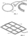
- FIG. 1 shows an example of a hose configured with small perforations 102 to introduce bubbles proximate the intake of a degasser. While the circular hose of FIG.
- a more aggressive air injection may be provided using a bubbler pattern that covers the entire base of the process tank.
- a hose 201 may be secured to a weighted frame 203.
- Such an arrangement provides more linear feet of the hose, or bubbler, and many more bubbles for a given process tank.
- many of the bubbles generated may be outside the immediate draw of the degasser.
- the degasser used must be effective to reduce foaming.
- a proper range of air bubbles introduced into the fluid may be determined by measuring flow rate of the air as a function of hose length and applied pressure, as shown in the Examples below.
- Figure 3 shows the resulting air injection rates achievable for varied lengths of soaker hose for a range of injection pressures. Fine bubble generation was limited to injection pressures of 0.172 MPa (25 psi) or lower. For shorter hose lengths, the air injection rate was limited due to over-pressuring of the hose. Accordingly, longer lengths of tubing are required to achieve high flow rates at low injection pressures. Thus, in this embodiment, approximately 50L/min of air per meter of hose is required to retain fine bubble generation.
- H has a value of 8.56 x 10⁻³ atm ⁇ m 3 /mol at 20°C. This relation applies to air and water in the degassing system strictly when the two phases are allowed to stand long enough in contact for all portions of the gas and liquid to come into equilibrium. For example, if pure water were allowed to stand in a atmosphere of pure H 2 S, the equilibrium concentration of dissolved H 2 S would be 3740 mg/L.
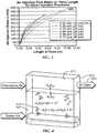
- air bubbles 419 are injected into a well fluid 420 contained in process tank 422. Entrained gases, for example hydrogen sulfide, may escape and fill the headspace volume 424. The gases that fill the headspace volume 424 are sent to flare 426.
- Entrained gases for example hydrogen sulfide
- water containing dissolved H 2 S may flow into a process tank with the following system limitations.
- the equilibrium concentration of H 2 S in the air space of the process tank may be determined as described below.
- a process tank may have a total volume of 8,000 L and may be loaded with 6,000L of water containing 1,000 mg/L of H 2 S. This leaves 2,000 L of vapor space.
- the air in the vapor space may be void of oxygen (for reasons discussed later).
- the pH is kept stable at 2.0 even as H 2 S leaves the fluid.
- the 6,000 L of water contains (1,000 mg/L x 6,000 L x 1g/1000mg x 1kg/1,000g) 6 kg of H 2 S.
- the molecular weight of H 2 S is approximately 34 g/mol, so there are (6 kg x 1000g/kg x 1 mol/34 g) 176.47 mol of H 2 S in the water.
- the mole fraction of H 2 S may be calculated as (moles H 2 S)/(moles water).
- One liter of water weighs nearly 1 kg, and the molecular weight of water is 18 g/mol.
- the number of moles of water can be determined by multiplying the total volume of static water by the fraction of mol/L. of water (55 mol/L x 6000 L) to yield 330,000 mol of water. Accordingly, the mole fraction of H 2 S is approximately (176.47/330,000) 0.000535.
- Hydrogen sulfide is an acid with two equivalents per mole, sequentially ionizing: H 2 S ⁇ H + + HS - and HS - ⁇ H + + S -2
- the second ionization constant is relatively low or weak such that S -2 is virtually non-existent in dilute aqueous systems.
- Henry's law (shown in Equation 1) holds only when there is no chemical reaction between the solute and solvent. Accordingly, the pH of the well fluid affects the hydrogen sulfide ionization and the H 2 S concentration. Thus, the liquid/gas equilibria of H 2 S is partially dependent on the ionization of the hydrogen sulfide.
- Sulfide in the form of HS - is not volatile. As shown in Figure 5 , as the pH falls below 6, the sulfide in the well fluid is more likely to be in the non-volatile, HS - , form.
- a buffer may be added to the fluid to maintain a pH of less than 6. For example, citric acid may be provided to hold the pH at 4.
- oxygen is sparged into the well fluid to remove hydrogen sulfide from the well fluid.
- Oxygen in the sparged air generally a nuisance to well fluids in the wellbore because of its corrosive nature, can be beneficial in sparging operations of general fluids.
- Hydrogen sulfide reacts with oxygen to become relatively harmless elemental sulfur.
- U.S. Patent No. 5,525,242 issued to Kerecz and U.S. Patent No. 6,352,943 issued to Kohlenberg describe methods of removing hydrogen sulfide by sparging with air . Additionally, the removal of air may be facilitated by dispersing the water as a mist or inducing a vortex.
- oxygen is a more effective sparging agent for scavenging hydrogen sulfide, because oxygen readily reacts with hydrogen sulfide.
- the thermodynamic drive to convert elemental oxygen into water by reacting with hydrogen sulfide to form elemental sulfur results in very low residual hydrogen sulfide.
- the kinetics of oxygen transfer across the gas/liquid interface may be a limiting factor; however, by using small bubbles rather than larger bubbles (as discussed below), this process may become more effective.
- the determination of how large a contribution oxygen makes to the removal of hydrogen sulfide in the well fluid is detailed below.
- E the maximum potential difference, or electromotive force
- R the thermodynamic gas constant
- T the absolute temperature
- F Faraday's constant
- n the number of electrons.
- 0.0592 V may replace RT/F in Equation 5 above.
- a system for removing hydrogen sulfide is shown in Figure 6 .
- H 2 S enters the system as soluble sulfides with well fluid 630 as it is flowed into process tank 632.
- the well fluid 630 pours into the process tank until it reaches a pre-selected depth corresponding to a pre-selected volume.
- the pre-selected depth corresponds to a volume of 6 m 3 of contained well fluid.
- Air 634 is sparged into the fluid 630.
- a mechanical degasser (not shown) coupled to the process tank 632 exerts a centrifugal force on the well fluid 630 to facilitate the escape of entrained gases into headspace volume 636.
- the removed entrained gases are sent to flare 638 for burning.
- the contained well fluid 630 spills over a weir arrangement in the process tank into a separate compartment.
- a mobile degassing system is provided to remove entrained and/or dissolved gases from a well fluid.
- a well fluid for example, a spent acid
- the well fluid undergoes a gross gas/liquid separation 702 in a unit upstream from the system, with the gases sent to a flare 713.
- At least one surge tank 703 regulates the flow of the well fluid before the well fluid enters a process tank containing at least one weir.
- the pH of the well fluid in the process tank is measured at 704.
- the pH of the well fluid may be measured by any method known in the art, and is not limited herein.
- acid is added, shown at 705, to the well fluid until a pH of less than 4 is reached.
- the acid added to the well fluid to maintain a pH of 4 may be citric acid.
- acids may be used to lower and maintain the pH of the well fluid.
- the level of fluid in the process tank is measured, shown at 706.
- the level of fluid in the process tank may be measured by any method known in the art, for example, electronically by a sensor or manually by a system operator. Once the liquid level has reached a predetermined value required for running a degasser, the degasser is turned on, shown at 707.
- the well fluid is aerated 708 by injecting or sparging air 709 through the fluid in the process tank.
- the fluid sparged through the well fluid is oxygen.
- the mechanical degasser and sparging are performed simultaneously. The centrifugal force of the mechanical degasser multiplies the force acting on the entrained gas bubbles and the oxygen bubbles to increase buoyancy and release of both the entrained gas bubbles and the oxygen bubbles. The increase in buoyancy of the bubbles accelerates the bubble-rise velocity. As the entrained gas bubbles and the oxygen bubbles rise toward the surface, they escape the well fluid.
- the oxygen injected into the well fluid may react with hydrogen sulfide dissolved in the fluid, thereby producing elemental sulfur, which may be more easily separated from the fluid.
- the well fluid rises to the level of the weir 710 due to the input flow of well fluid and aeration of the tank, the well fluid pours over the weir and empties into another containment. The outfall well fluid 711 may then be safely disposed.
- the aeration and degassing system may be continuously operated for a period of time. In one embodiment, the aeration and degassing system is continuously operated for approximately 8 to 10 hours at a time. After aeration and degassing may be stopped periodically during the process to remove elemental sulfur from the process tank that results from the reaction between oxygen sparged into the well fluid and entrained hydrogen sulfide.
- 6,000L of well fluid with a pH of 2.0 contained in a 8,000L process tank is sparged with zero air at a rate of 1,000 L/min.
- the amount of sulfur reduced over time as a result of the sparging is shown in Figure 10 for both the well fluid in the process tank and the well fluid that spills over the weir. Sparging the well fluid with zero air at 1,000 L/min results in larger reduction in sulfur content than sparging the well fluid with zero air at 100 L/min.
- 6,000L of well fluid with a pH of 2.0 contained in a 8,000L process tank is sparged with zero air at a rate of 10,000 L/min. Sparging the well fluid with zero air at 10,000 L/min results in significant and immediate reduction in sulfides, as shown in Figure 11 for both the well fluid in the process tank and the well fluid that spills over the weir.
- Figure 12 shows the result of a system where the pH is 8 and zero air is sparged through the well fluid at a rate of 1,000 L/min for both the well fluid in the process tank and the well fluid that spills over the weir.
- Figure 12 (pH 8) and Figure 10 (pH 2) shows the extraction of hydrogen sulfide in the higher pH well fluid its much less efficient than in the well fluid with a lower pH.
- embodiments of the present invention provide a system and method for reducing the amount of hydrogen sulfide in a well fluid. Further, embodiments of the present invention may reduce the risks to both the structure of the well and personnel associated with circulating well fluid, including embrittled tubulars, corrosion of equipment, and death.
Landscapes
- Engineering & Computer Science (AREA)
- Life Sciences & Earth Sciences (AREA)
- Mining & Mineral Resources (AREA)
- Geology (AREA)
- Mechanical Engineering (AREA)
- Physics & Mathematics (AREA)
- Environmental & Geological Engineering (AREA)
- Fluid Mechanics (AREA)
- Chemical & Material Sciences (AREA)
- Chemical Kinetics & Catalysis (AREA)
- General Life Sciences & Earth Sciences (AREA)
- Geochemistry & Mineralogy (AREA)
- Degasification And Air Bubble Elimination (AREA)
- Physical Water Treatments (AREA)
Description
- The invention relates generally to a method for treating well fluids.
- When drilling or completing wells in earth formations, various fluids typically are used in the well for a variety of reasons. Common uses for well fluids include: lubrication and cooling of drill bit cutting surfaces while drilling generally or drilling-in (i.e., drilling in a targeted petroleum bearing formation), transportation of "cuttings" (pieces of formation dislodged by the cutting action of the teeth on a drill bit) to the surface, controlling formation fluid pressure to prevent blowouts, maintaining well stability, suspending solids in the well, minimizing fluid loss into and stabilizing the formation through which the well is being drilled, fracturing the formation in the vicinity of the well, displacing the fluid within the well with another fluid, cleaning the well, testing the well, implacing a packer fluid, abandoning the well or preparing the well for abandonment, and otherwise treating the well or the formation.
- In drilling some subterranean formations, and particularly those bearing oil or gas, hydrogen sulfide accumulations are frequently encountered. The circulation of well fluid brings the hydrogen sulfide from the formation to the surface. Such sulfide in the well fluid is problematic, as it can corrode the steel in the drilling apparatus and may be liberated into the atmosphere as toxic sulfide gas at the well surface. Further, hydrogen sulfide contaminated oil from the well fluid may become associated with or absorbed to the surfaces of the cuttings that are removed from the formation being drilled. The cuttings are then an environmentally hazardous material, making disposal a problem.
- Generally, to protect the health of those working with the well fluid and those at the surface of the well, conditions should be maintained to ensure that the concentration of hydrogen sulfide released from the fluid, emitted due to the partial pressure of the gas, is less than about 15 ppm. The partial pressure of hydrogen sulfide at ambient temperatures is a function of the concentration of sulfide ions in the fluid and the pH of the fluid. To ensure that the limit of 15 ppm is not exceeded even for the maximum sulfide concentration that may be encountered in a subterranean formation, the pH of the well fluid is typically maintained at a minimum of about 11.5. Also, to prevent the soluble sulfide concentration in the well fluid from becoming excessive, action is routinely taken to remove sulfide from the well fluid.
- Dissolved gases cause many problems in the oil field. Gases and other fluids present in subterranean formations, collectively called reservoir fluids, are prone to enter a wellbore drilled through the formation. In many cases, dense drilling fluids, completion brines, fracturing fluids, and so forth are provided to maintain a countering pressure that restrains the reservoir fluids from entering the wellbore. However, there are many instances where the counter pressure is too low to restrain the reservoir fluids. This may be due to, for example, a miscalculation of the fluid density needed to maintain a hydrostatic overbalance or a transient lowering of pressure due to movement of the drill string in the hole. Gasses may also enter the wellbore through molecular diffusion if there is insufficient flux of fluid from the wellbore to keep it swept away. Finally, reservoir fluids escape from the fragments of the formation that are being drilled up. The reservoir fluid that enters the well is then free to mix with the supplied well fluid and rise to the surface.
- The hazards of unrestrained expansions of reservoir fluids in the wellbore are well known. A primary hazard is an avalanche effect of gas evolution and expansion, wherein gas bubbles rise in a liquid stream, expanding as they rise. As the bubbles expand, they expel dense fluid from the bore, and further reduce the hydrostatic pressure of the wellbore fluid. Such a progression may eventually lead to a 'blow out', whereby so much restraining pressure has been lost that the high pressure reservoir can flow uncontrollably into the wellbore.
- Less dramatic, but equally important, are chemical effects that formation fluids may have upon the circulating fluid, the structure of the well, and the associated personnel. These effects and risks may include, for example: methane gas liberated at the surface may ignite; carbon dioxide may become carbonic acid, a highly corrosive compound, when exposed to water; carbon dioxide gas is an asphyxiant; hydrogen sulfide can corrode ferrous metals, particularly in contact with water, and is more damaging than carbon dioxide because it can induce hydrogen embrittlement; embrittled tubulars may separate or break well under design stresses with catastrophic consequences; hydrogen sulfide gas is also toxic, with levels of 800 to 1000 ppm causing death in healthy individuals. Removing dissolved and entrained gases is thus vital to many aspects of successful drilling and exploitation.
- Chemical processes have been previously used to ameliorate the effects of dissolved gasses, particularly of hydrogen sulfide and carbon dioxide. Caustic and similar high-pH materials, for example, sodium hydroxide, are added to circulating well fluid to maintain pH. Copper, zinc, and iron compounds have been added to react with and sequester hydrogen sulfide, although they often have deleterious effects on circulating fluid properties and can cause environmental disposal issues. Oxidants, such as hypochlorite, have also been proposed, but they may have destructive effects on organic and metal components.
-
US 4 108 619 describes a degasser spray vessel. - Accordingly, there exists a need for a method and apparatus to facilitate the removal of entrained and dissolved gases in a well fluid. Further, there exists a need for a method and apparatus to facilitate the destruction and removal of hydrogen sulfide in a well fluid.
- In one aspect, the invention relates to a method of reducing entrained and dissolved gases from a well fluid, the method including flowing a well fluid into a process tank, exerting a centrifugal force on the well fluid, wherein a mechanical degasser coupled to the process tank is configured to exert the centrifugal force on the well fluid, and generating bubbles into the well fluid proximate an intake of the mechanical degasser, wherein generating bubbles in the well fluid comprises injecting gas into the well fluid, the gas injected into the well fluid comprising oxygen.
- Embodiments and advantages of the invention will be apparent from the following description and the appended claims.
-
-
FIG. 1 shows a hose configuration in accordance with an embodiment of the invention. -
FIG. 2 shows a hose configuration in accordance with an embodiment of the invention. -
FIG. 3 shows a chart of air injection rates against length of time in accordance with an embodiment of the invention. -
FIG. 4 shows a system diagram in accordance with an embodiment of the invention. -
FIG. 5 shows a chart of amount of hydrogen sulfide reduced with respect to pH in accordance with an embodiment of the invention. -
FIG. 6 shows a system diagram in accordance with an embodiment of the invention. -
FIG. 7 shows a flow diagram of a degassing system in accordance with an embodiment of the invention. -
FIG. 8 shows a chart of amount of hydrogen sulfide with respect to time of in accordance with an embodiment of the invention. -
FIG. 9 shows a chart of amount of hydrogen sulfide reduced with respect to time in accordance with an embodiment of the invention. -
FIG. 10 shows a chart of amount of hydrogen sulfide reduced with respect to time in accordance with an embodiment of the invention. -
FIG. 11 shows a chart of amount of hydrogen sulfide reduced with respect to time in accordance with an embodiment of the invention. -
FIG. 12 shows a chart of amount of hydrogen sulfide reduced with respect to time in accordance with an embodiment of the invention. -
FIG. 13 shows a chart of amount of hydrogen sulfide reduced with respect to time in accordance with an embodiment of the invention. -
FIG. 14 shows a chart of amount of hydrogen sulfide reduced with respect to time in accordance with an embodiment of the invention. -
FIG. 15 shows a chart of amount of hydrogen sulfide reduced with respect to time in accordance with an embodiment of the invention. - In one aspect, embodiments of the invention are directed to a novel method for removing entrained and/or dissolved gases from a well fluid. For example, embodiments of the invention are directed to a novel method for removing hydrogen sulfide, H2S, from well fluids. Embodiments of the invention include both physically removing the entrained and/or dissolved gas for flaring and chemical conversion of the gas into non-toxic, non-corrosive forms. Embodiments of the invention include removal or destruction of H2S through at least three processes, including partition of the H2S between gas and liquid phases, acid/base equilibria between dissolved sulfide species, and electrochemical equilibria between dissolved H2S, oxygen (O2), sulfur (S), and water (H2O). Embodiments of the present invention involve degassing and aeration apparatuses. Exemplary apparatuses are described below.
- Degassers assist in maintaining a circulating fluid density so as to maintain needed hydrostatic pressure of the well fluid. A degasser applies a vacuum to a fluid and subjects the fluid to centripetal acceleration. The fluid is then sprayed against a surface, thereby removing entrained air and slowly-evolving bubbles of dissolved formation gases from the circulating fluid before its return downhole or before the fluids disposal.
- According to the invention, a mechanical degasser, for example, a MI SWACO® CD-1400, available from M-I, LLC (Houston, TX) is coupled to a process tank. The well fluid passes through the mechanical degasser wherein centrifugal force is exerted on the well fluid. The centrifugal force of the mechanical degasser multiplies the force acting on the entrained gas bubbles, for example, hydrogen sulfide, to increase buoyancy of the gas bubbles, thereby releasing the entrained gas bubbles from the well fluid. The increase in buoyancy of the gas bubbles accelerates the bubble-rise velocity. As the bubbles rise toward the surface, they escape the well fluid. One of ordinary skill in the art will appreciate that any device known in the art that will exert a centrifugal force on the fluid may be used in place of a mechanical degasser.
- Sparging air through liquids strips both super-saturated and sub-saturated dissolved gases by carrying them out of the liquid. If the dissolved gas is not present in the gas used to sparge, the partial pressure of the dissolved gas is accordingly zero. Thus, the dissolved gases partition into the introduced, or sparged, gas bubble. With sparging at a constant rate under conditions of vapor/dissolved gas equilibrium, the reduction of dissolved gas proceeds exponentially, limited only by the total volume of sparge gas. The volume of dissolved gas removed from the fluid, in many instances, is limited by the rate in which the sparge gas bubbles can rise through the fluid and emerge. Attempts to pump high volumes of sparge gas become frustrated as the bubble content increases, because the viscosity of the bubble/liquid system increases, thereby hindering the rise of bubbles.
- The rate of oxygen transfer across the air/fluid interface can only be determined empirically. For a fixed volume of air sparged through a fluid, mass transfer of gases into and out of the fluid is be a strong function of the surface area at the air/gas interface. Further, the more time each bubble resides in the liquid, the more complete the exchange. The Stokes-Einstein equation shows that residence time is primarily a function of the bubble diameter, gross density of the media, and system viscosity. The Stokes-Einstein equation may be written D=kT/ƒ where D is the diffusion coefficient, k is the Boltzmann constant, T is the absolute temperature, and ƒ is the frictional coefficient, wherein ƒ=6πaη, where a is the radius of a particle and η is the viscosity of a solvent. Small bubbles have larger surface area per volume and rise more slowly as compared to larger bubbles. Additionally, at higher concentrations, small bubbles will viscosify a fluid. Accordingly, a high volume fraction of small bubbles will provide greater reaction with hydrogen sulfide than a low volume fraction of large bubbles. "Small" and "large", as used herein with reference to the bubble, are relative to the rate at which the bubbles rise in a given system under a given set of conditions including rate of air injection, temperature, fluid viscosity, etc.
- Bubbles may be generated by any method known in the art. For example, bubbles may be generated by an aeration device. In one embodiment the aeration device may include a septum or membrane configured with small perforations through which air may be released. In one embodiment, the membrane may be flexible, such as a woven or non-woven fabric, or a sheet of rubber or other elastomer with perforated openings cast or otherwise formed therethrough. Alternatively, the membrane may be rigid, for example a solid frit, which is a body of sintered particles with fine openings between particles, or a metal surface with fine perforations, or openings devised by any means known in the art. Examples of such commercially available porous septa and perforated media are given in, for example, Chapter 18 of Perry's Chemical Engineers' Handbook, 6th ed (1984). Further, bubbles may be created by passing gas through a surface free of openings, such as permeating hydrogen through a palladium film, at a lower flux. One of ordinary skill in the art will appreciate, however, that the membrane may be constructed of any of a number of materials known in the art, for example, glass, metal, plastic, etc., such that air may be sparged into the fluid. Bubbles may also be generated through direct mechanical means, wherein air is entrained in a well fluid by mixing. Further, bubbles may be generated through chemical means by various reactions known in the art that may convert solid or liquid components into gases.
- In another embodiment, bubbles may be generated through destabilizing a gas-liquid solution. Bubbles may spontaneously form when the pressure or temperature of a liquid is changed from a previous state of gas/liquid saturation. Commercially, Dissolved Air Flotation (DAF) saturates water with air at higher applied pressure, for example, 0.689 MPa (100 psi), and then reduces the pressure of the system. The water may then be allowed to flow from a closed pressured conduit or vessel into a large vessel open to the atmosphere. Several commercial devices and processes for generating bubbles by destabilizing a gas-liquid solution are cited in Perry's Chemical Engineers' Handbook, 6th ed (1984).
- According to the invention, bubbles are generated proximate an intake of a degasser. In one embodiment, a flexible, porous hose may sparge air into a fluid. The flexible, porous hose may be attached to weighted frames by any method known in the art, for example, by plastic ties or wire wrap. The hose may be fashioned into any shape using standard hose fittings. In one embodiment, the hose may be disposed proximate the intake of a degasser.
FIG. 1 shows an example of a hose configured withsmall perforations 102 to introduce bubbles proximate the intake of a degasser. While the circular hose ofFIG. 1 provides short air/water contact times, it minimizes the opportunities for foaming, thereby reducing the risks involved in introducing air into a fluid. In another embodiment, shown inFIG. 2 , a more aggressive air injection may be provided using a bubbler pattern that covers the entire base of the process tank. Ahose 201 may be secured to aweighted frame 203. Such an arrangement provides more linear feet of the hose, or bubbler, and many more bubbles for a given process tank. For a hose that covers the entire base of a tank, many of the bubbles generated may be outside the immediate draw of the degasser. In this embodiment, the degasser used must be effective to reduce foaming. - In order to maintain the integrity of the porous hose and the proper bubble size, a proper range of air bubbles introduced into the fluid may be determined by measuring flow rate of the air as a function of hose length and applied pressure, as shown in the Examples below.
- To determine the bubble size and volume fraction of bubbles, empirical testing was done using an open, rectangular tank with a degasser unit, for example, MI SWACO® CD-1400, mounted in the process tank. In this test, the process tank was filled with potable water to within 44.8 cm (17 and 5/8 inches) of the top, that is 6.4 m3 (1700 gal) of water. A circular hose, shown in
Figure 1 , introduced bubbles at the base of the degasser. -
Figure 3 shows the resulting air injection rates achievable for varied lengths of soaker hose for a range of injection pressures. Fine bubble generation was limited to injection pressures of 0.172 MPa (25 psi) or lower. For shorter hose lengths, the air injection rate was limited due to over-pressuring of the hose. Accordingly, longer lengths of tubing are required to achieve high flow rates at low injection pressures. Thus, in this embodiment, approximately 50L/min of air per meter of hose is required to retain fine bubble generation. - Partition of the H2S between gas and liquid phases is a kinetic process that approaches a thermodynamic equilibrium described by Henry's Law:

- In one embodiment, as shown in
Figure 4 , air bubbles 419 are injected into a well fluid 420 contained inprocess tank 422. Entrained gases, for example hydrogen sulfide, may escape and fill theheadspace volume 424. The gases that fill theheadspace volume 424 are sent to flare 426. - In one embodiment, water containing dissolved H2S may flow into a process tank with the following system limitations. The equilibrium concentration of H2S in the air space of the process tank may be determined as described below. In one example, a process tank may have a total volume of 8,000 L and may be loaded with 6,000L of water containing 1,000 mg/L of H2S. This leaves 2,000 L of vapor space. The air in the vapor space may be void of oxygen (for reasons discussed later). In this example, the pH is kept stable at 2.0 even as H2S leaves the fluid. The following table summarizes the initial conditions of the system.
Table 1 H2S in Water (mg/L) 1000 H2S in Air (ppm by volume) 0 Volume of static air (L) 2,000 Volume of static water (L) 6,000 pH 2.0 - The 6,000 L of water contains (1,000 mg/L x 6,000 L x 1g/1000mg x 1kg/1,000g) 6 kg of H2S. The molecular weight of H2S is approximately 34 g/mol, so there are (6 kg x 1000g/kg x 1 mol/34 g) 176.47 mol of H2S in the water.
- Neglecting the very small amount of water displaced by the gas, the mole fraction of H2S may be calculated as (moles H2S)/(moles water). One liter of water weighs nearly 1 kg, and the molecular weight of water is 18 g/mol. Thus, there are (1 kg x 1000g/kg x 1 mol/18 g) 55 mol/L of water. The number of moles of water can be determined by multiplying the total volume of static water by the fraction of mol/L. of water (55 mol/L x 6000 L) to yield 330,000 mol of water. Accordingly, the mole fraction of H2S is approximately (176.47/330,000) 0.000535.
- The air space is initially free of H2S, and to fill it requires that H2S leave the liquid. This reduces the mole fraction, thereby reducing the calculated equilibrium. To solve, consider the mass balance:


- To convert the moles air space sulfur, SA, to a mole fraction gas, the ideal gas law may be used to first determine the volume of H2S gas. Assuming a constant temperature of 25°C, the ideal gas law may be expressed as (PV=nRT, RT is constant) 22.4 (L*atm/mol)*n=PV, where n is the number of moles, P is the pressure, and V is the volume.

- Next, dividing by total volume to get the partial pressure:

- Substituting for SA,

- As above, the mole fraction in the liquid is:

- Now, substituting for the variables in Henry's Law:


- Solving for the moles of liquid phase sulfur, SL = 175.68 mol.
- And then plugging the value of SL into Equation 3, gives SA:

- From the above, it is apparent that putting the fluid into a process tank and letting the H2S escape does very little to reduce the H2S content in the fluid. If the system is to be effective, there must be a much larger volume of gas into which the H2S can escape. Because the process tank size is fixed, and cannot be pressured, volume of gas into which the H2S can escape may only be increased by passing gas through the process tank.
- The importance of maintaining the pH of the fluid and the determination of a pH threshold for effective stripping of hydrogen sulfide from the well fluid is illustrated below.
- Hydrogen sulfide is an acid with two equivalents per mole, sequentially ionizing:
H2S ↔ H+ + HS-
and
HS- ↔ H+ + S-2
- Hydrogen sulfide is a mild acid as shown by its acidity constants:


- The second ionization constant is relatively low or weak such that S-2 is virtually non-existent in dilute aqueous systems. Henry's law (shown in Equation 1) holds only when there is no chemical reaction between the solute and solvent. Accordingly, the pH of the well fluid affects the hydrogen sulfide ionization and the H2S concentration. Thus, the liquid/gas equilibria of H2S is partially dependent on the ionization of the hydrogen sulfide. Sulfide in the form of HS- is not volatile. As shown in
Figure 5 , as the pH falls below 6, the sulfide in the well fluid is more likely to be in the non-volatile, HS-, form. In one embodiment, a buffer may be added to the fluid to maintain a pH of less than 6. For example, citric acid may be provided to hold the pH at 4. - In one embodiment, oxygen is sparged into the well fluid to remove hydrogen sulfide from the well fluid. Oxygen in the sparged air, generally a nuisance to well fluids in the wellbore because of its corrosive nature, can be beneficial in sparging operations of general fluids. Hydrogen sulfide reacts with oxygen to become relatively harmless elemental sulfur.
U.S. Patent No. 5,525,242 issued to Kerecz andU.S. Patent No. 6,352,943 issued to Kohlenberg describe methods of removing hydrogen sulfide by sparging with air . Additionally, the removal of air may be facilitated by dispersing the water as a mist or inducing a vortex. - While nitrogen may be used in sparging processes, oxygen is a more effective sparging agent for scavenging hydrogen sulfide, because oxygen readily reacts with hydrogen sulfide. The thermodynamic drive to convert elemental oxygen into water by reacting with hydrogen sulfide to form elemental sulfur results in very low residual hydrogen sulfide. The kinetics of oxygen transfer across the gas/liquid interface may be a limiting factor; however, by using small bubbles rather than larger bubbles (as discussed below), this process may become more effective. The determination of how large a contribution oxygen makes to the removal of hydrogen sulfide in the well fluid is detailed below.
- Air oxidation takes place via the reaction:
2H 2 S + O 2 → 2S + 2H 2 O (4)
- A one-sided arrow is used to indicate the reaction goes in only one direction, because the equilibrium between the products and reactants is very large. The equilibrium is written:

- The value of K may be determined by the Nernst equation:

- The overall reaction may be written as:
O2(g) + 4H+ + 2S-2 → 2H2O (6)
- The half-cell reactions and corresponding oxidation potentials of the oxidation reaction shown in
Equation 6 are:
O2(g) + 4H+ + 4e- → 2H2O E0 = 1.229 V
S + 2H+ + 2e- → H2S E0 = 0.142 V
- Therefore, the potential of the overall reaction is (1.229-0.142) 1.077. The number of electrons, n, is 4. Plugging these values back into the Nernst Equation (Equation 5) yields:

- Accordingly, essentially all of the oxygen is consumed with concomitant destruction of hydrogen sulfide.
- In one embodiment, a system for removing hydrogen sulfide is shown in
Figure 6 . H2S enters the system as soluble sulfides with well fluid 630 as it is flowed intoprocess tank 632. The well fluid 630 pours into the process tank until it reaches a pre-selected depth corresponding to a pre-selected volume. For example, in one embodiment, the pre-selected depth corresponds to a volume of 6 m3 of contained well fluid.Air 634 is sparged into thefluid 630. A mechanical degasser (not shown) coupled to theprocess tank 632 exerts a centrifugal force on the well fluid 630 to facilitate the escape of entrained gases intoheadspace volume 636. The removed entrained gases are sent to flare 638 for burning. As the well fluid 630 level in theprocess tank 632 rises above the pre-selected depth of contained well fluid due to the input flow of well fluid and thesparged air 634, the contained well fluid 630 spills over a weir arrangement in the process tank into a separate compartment. - In one embodiment, as shown in
Figure 7 , a mobile degassing system is provided to remove entrained and/or dissolved gases from a well fluid. In this embodiment, a well fluid, for example, a spent acid, is flowed back 701 from the well. The well fluid undergoes a gross gas/liquid separation 702 in a unit upstream from the system, with the gases sent to aflare 713. At least onesurge tank 703 regulates the flow of the well fluid before the well fluid enters a process tank containing at least one weir. The pH of the well fluid in the process tank is measured at 704. The pH of the well fluid may be measured by any method known in the art, and is not limited herein. If the well fluid has a pH greater than 4, then acid is added, shown at 705, to the well fluid until a pH of less than 4 is reached. In one embodiment, the acid added to the well fluid to maintain a pH of 4 may be citric acid. One of ordinary skill in the art will appreciate that other acids may be used to lower and maintain the pH of the well fluid. - If the pH of the well fluid is less than 4, then the level of fluid in the process tank is measured, shown at 706. One of ordinary skill in the art will appreciate that the level of fluid in the process tank may be measured by any method known in the art, for example, electronically by a sensor or manually by a system operator. Once the liquid level has reached a predetermined value required for running a degasser, the degasser is turned on, shown at 707.
- In one embodiment, the well fluid is aerated 708 by injecting or
sparging air 709 through the fluid in the process tank. In one embodiment, the fluid sparged through the well fluid is oxygen. In one embodiment, the mechanical degasser and sparging are performed simultaneously. The centrifugal force of the mechanical degasser multiplies the force acting on the entrained gas bubbles and the oxygen bubbles to increase buoyancy and release of both the entrained gas bubbles and the oxygen bubbles. The increase in buoyancy of the bubbles accelerates the bubble-rise velocity. As the entrained gas bubbles and the oxygen bubbles rise toward the surface, they escape the well fluid. Additionally, the oxygen injected into the well fluid may react with hydrogen sulfide dissolved in the fluid, thereby producing elemental sulfur, which may be more easily separated from the fluid. When the well fluid rises to the level of theweir 710 due to the input flow of well fluid and aeration of the tank, the well fluid pours over the weir and empties into another containment. The outfall well fluid 711 may then be safely disposed. - The aeration and degassing system may be continuously operated for a period of time. In one embodiment, the aeration and degassing system is continuously operated for approximately 8 to 10 hours at a time. After aeration and degassing may be stopped periodically during the process to remove elemental sulfur from the process tank that results from the reaction between oxygen sparged into the well fluid and entrained hydrogen sulfide.
- As a first example, consider the case where no sparging occurs. Assume a total of 20m3 of well fluid having a pH of 2.0 to be treated and a feed rate of the well fluid is 800 L/min. Initially, the well fluid flows into a process tank having a volume of 8,000L. Once 6 m3 of well fluid has poured into the process tank, the well fluid will begin to spill over the weir. The well fluid in the process tank and the well fluid that spills over the weir retain 1,000 mg/L dissolved sulfides. Accordingly, no sulfur is removed from the well fluid.
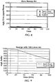
Figure 8 shows the relationship between well fluid in the process tank, the well fluid that spills over the weir, and the moles of sulfur gas. - In another example, 6,000L well fluid with a pH of 2.0 contained in a 8,000L process tank is sparged with "zero air," that is, air that contains no oxygen, at a rate of 100 L/min. Sparging the well fluid with zero air at 100 L/min results in modest hydrogen sulfide stripping. As shown in
Figure 9 , spent well fluid in the process tank is continuously stripped of hydrogen sulfide, but even after 100 minutes only a level of about 580 mg/L sulfur is reached for the 6 m3 of well fluid retained in the unit. - In another example, 6,000L of well fluid with a pH of 2.0 contained in a 8,000L process tank is sparged with zero air at a rate of 1,000 L/min. The amount of sulfur reduced over time as a result of the sparging is shown in
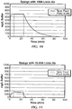
Figure 10 for both the well fluid in the process tank and the well fluid that spills over the weir. Sparging the well fluid with zero air at 1,000 L/min results in larger reduction in sulfur content than sparging the well fluid with zero air at 100 L/min. - In another example, 6,000L of well fluid with a pH of 2.0 contained in a 8,000L process tank is sparged with zero air at a rate of 10,000 L/min. Sparging the well fluid with zero air at 10,000 L/min results in significant and immediate reduction in sulfides, as shown in
Figure 11 for both the well fluid in the process tank and the well fluid that spills over the weir. - If the pH is raised to a pH value of 8 in the sparging system described in Example 4 above, the extraction of hydrogen sulfide is less efficient.
Figure 12 shows the result of a system where the pH is 8 and zero air is sparged through the well fluid at a rate of 1,000 L/min for both the well fluid in the process tank and the well fluid that spills over the weir. A comparison betweenFigure 12 (pH 8) andFigure 10 (pH 2) shows the extraction of hydrogen sulfide in the higher pH well fluid its much less efficient than in the well fluid with a lower pH. - If the well fluid in the process tank of Example 2 is sparged with oxygen, instead of zero air, at the same rate of 100 L/min, the instantaneous stripping of hydrogen sulfide does not drastically improve. However, the final amount of sulfur concentration present in the well fluid is reduced. See
Figure 13 . - If the well fluid in the process tank of Example 3 is sparged with oxygen, instead of zero air, at the same rate of 1,000 L/min, the sulfur concentration present in the well fluid is significantly reduced. As shown in
Figure 14 , the reactions are complete in less than 40 minutes. - If the well fluid in the process tank of Example 5 is sparged with oxygen, instead of zero air, at the same rate of 10,000 L/min, sulfur present in the well fluid is destroyed and extracted in real time, as shown in
Figure 15 . This example assumes perfect mass-transport across the gas/liquid interface. - Advantageously, embodiments of the present invention provide a system and method for reducing the amount of hydrogen sulfide in a well fluid. Further, embodiments of the present invention may reduce the risks to both the structure of the well and personnel associated with circulating well fluid, including embrittled tubulars, corrosion of equipment, and death.
Claims (12)
- A method of reducing entrained and dissolved gases from a well fluid comprising:flowing a well fluid into a process tank;exerting a centrifugal force on the well fluid;wherein a mechanical degasser coupled to the process tank is configured to exert the centrifugal force on the well fluid; andgenerating bubbles into the well fluid proximate an intake of the mechanical degasser,wherein generating bubbles in the well fluid comprises injecting gas into the well fluid, the gas injected into the well fluid comprising oxygen.
- The method of claim 1, wherein the gas injected into the well fluid is air.
- The method of claim 1, further comprising determining the pH of the well fluid in the process tank.
- The method of claim 3, further comprising maintaining the pH of the well fluid in the process tank below a predetermined value.
- The method of claim 4, wherein maintaining the pH of the well fluid comprises supplying an acid to the well fluid in the process tank.
- The method of claim 5, wherein the acid is citric acid.
- The method of claim 1, further comprising flaring the gas.
- The method of claim 1, wherein exerting a centrifugal force on the well fluid is performed after the well fluid reaches a predetermined volume of the process tank.
- The method of claim 1, further comprising spilling the well fluid in the process tank over a weir.
- The method of claim 2, wherein generating bubbles comprises injecting air through a hose comprising at least one perforation.
- The method of claim 10, wherein the hose comprises one selected from the group consisting of elastomer, frits, glass, metal, plastic, and any combination thereof.
- The method of claim 2, wherein exerting a centrifugal force on the well fluid and the injecting the air into the well fluid are performed simultaneously.
Applications Claiming Priority (2)
| Application Number | Priority Date | Filing Date | Title |
|---|---|---|---|
| US77637206P | 2006-02-24 | 2006-02-24 | |
| PCT/US2007/004894 WO2007100750A2 (en) | 2006-02-24 | 2007-02-23 | Aerated degasser |
Publications (3)
| Publication Number | Publication Date |
|---|---|
| EP1986757A2 EP1986757A2 (en) | 2008-11-05 |
| EP1986757A4 EP1986757A4 (en) | 2012-03-28 |
| EP1986757B1 true EP1986757B1 (en) | 2017-02-08 |
Family
ID=38459602
Family Applications (1)
| Application Number | Title | Priority Date | Filing Date |
|---|---|---|---|
| EP07751638.3A Not-in-force EP1986757B1 (en) | 2006-02-24 | 2007-02-23 | Aerated degasser |
Country Status (7)
| Country | Link |
|---|---|
| US (1) | US7753990B2 (en) |
| EP (1) | EP1986757B1 (en) |
| CA (2) | CA2642792C (en) |
| EA (1) | EA016519B1 (en) |
| MX (1) | MX2008010771A (en) |
| NO (1) | NO20084027L (en) |
| WO (1) | WO2007100750A2 (en) |
Families Citing this family (7)
| Publication number | Priority date | Publication date | Assignee | Title |
|---|---|---|---|---|
| US8613360B2 (en) | 2006-09-29 | 2013-12-24 | M-I L.L.C. | Shaker and degasser combination |
| US20080164068A1 (en) * | 2006-12-21 | 2008-07-10 | M-I Llc | System and method for cleaning drill cuttings with degassed water |
| CA2848495C (en) * | 2011-09-23 | 2018-10-30 | Advanced Technologies & Innovations B.V. | Spherical separation device and method for separation |
| US9346677B2 (en) * | 2012-08-29 | 2016-05-24 | Sandvik Process Systems Llc | Sulfur degasser apparatus and method |
| CA3112371A1 (en) * | 2018-09-06 | 2020-03-12 | Swade HOLOWATUK | Process and system for removing hydrogen sulfide from sour water |
| US11646002B2 (en) | 2021-02-01 | 2023-05-09 | Bryan PAIGE | Capo for use with a stringed musical instrument, and method of using same |
| US11813551B1 (en) | 2021-11-22 | 2023-11-14 | Viro Petroleum & Energy, LLC | Hydrogen sulfide mitigation methods and systems |
Family Cites Families (19)
| Publication number | Priority date | Publication date | Assignee | Title |
|---|---|---|---|---|
| US4010012A (en) * | 1975-02-03 | 1977-03-01 | Dresser Industries, Inc. | Total gas containment system |
| US3977972A (en) * | 1975-04-02 | 1976-08-31 | Exxon Research And Engineering Company | Method and apparatus for reclaiming contaminated liquid |
| GB1591899A (en) * | 1976-12-27 | 1981-07-01 | Dresser Ind | Degasser spray vessel |
| US4412924A (en) * | 1981-12-29 | 1983-11-01 | Feather Orval R | Water purification system |
| GB8508690D0 (en) * | 1985-04-03 | 1985-05-09 | Ici Plc | Deaerating water |
| DE3765939D1 (en) * | 1986-06-12 | 1990-12-06 | Wilke Engelbart | METHOD AND DEVICE FOR LARGE-SCALE, FINE-BUBBLE GASING OF LIQUIDS. |
| SU1431798A1 (en) | 1986-06-23 | 1988-10-23 | Сибирский научно-исследовательский институт нефтяной промышленности | Method of preparing petroleum |
| SU1634295A1 (en) | 1989-03-20 | 1991-03-15 | Предприятие П/Я Г-4882 | Device for degassing of liquid |
| CZ278400B6 (en) * | 1991-08-30 | 1993-12-15 | Ludwig Scheibinger | Apparatus for aeration of a tank with a liquid |
| US5516360A (en) | 1994-04-08 | 1996-05-14 | Baker Hughes Incorporated | Abrasion resistant gas separator |
| US5525242A (en) | 1994-10-19 | 1996-06-11 | Kerecz; Robert C. J. | Apparatus and process for the aeration of water |
| US5673752A (en) | 1995-12-22 | 1997-10-07 | Scudder; Pat | Method and apparatus for producing gas from a formation containing both gas and water |
| US5900137A (en) * | 1996-06-27 | 1999-05-04 | Homan; Edwin Daryl | Apparatus and method for separating components in well fluids |
| FR2762043B1 (en) | 1997-04-14 | 1999-06-25 | Inst Francais Du Petrole | ELASTIC WAVES EXPLORATION TOOL FOR WELLS |
| US6103108A (en) | 1998-09-24 | 2000-08-15 | Kohlenberg; Larry D. | Water treatment apparatus |
| US6143709A (en) | 2000-03-28 | 2000-11-07 | Carey; Charles C. | Well cleaning stimulation and purging method |
| US6673135B2 (en) * | 2002-02-08 | 2004-01-06 | National Tank Company | System and method of separating entrained immiscible liquid component of an inlet stream |
| US7282081B2 (en) * | 2004-08-12 | 2007-10-16 | Verscharen John A | Method and apparatus for high efficiency multi-stage packed tower aeration with PH adjustment and reutilization of outlet air |
| NO330765B1 (en) * | 2006-03-15 | 2011-07-11 | Hamworthy Plc | Tank for processing fluids and system for processing well fluids comprising such a tank |
-
2007
- 2007-02-22 US US11/677,829 patent/US7753990B2/en not_active Expired - Fee Related
- 2007-02-23 CA CA2642792A patent/CA2642792C/en not_active Expired - Fee Related
- 2007-02-23 CA CA2755939A patent/CA2755939C/en not_active Expired - Fee Related
- 2007-02-23 EA EA200870293A patent/EA016519B1/en not_active IP Right Cessation
- 2007-02-23 WO PCT/US2007/004894 patent/WO2007100750A2/en not_active Ceased
- 2007-02-23 EP EP07751638.3A patent/EP1986757B1/en not_active Not-in-force
- 2007-02-23 MX MX2008010771A patent/MX2008010771A/en active IP Right Grant
-
2008
- 2008-09-22 NO NO20084027A patent/NO20084027L/en not_active Application Discontinuation
Non-Patent Citations (1)
| Title |
|---|
| None * |
Also Published As
| Publication number | Publication date |
|---|---|
| WO2007100750A2 (en) | 2007-09-07 |
| WO2007100750A3 (en) | 2007-11-01 |
| EA200870293A1 (en) | 2009-02-27 |
| NO20084027L (en) | 2008-11-19 |
| MX2008010771A (en) | 2008-09-01 |
| CA2755939C (en) | 2013-11-26 |
| EP1986757A4 (en) | 2012-03-28 |
| US7753990B2 (en) | 2010-07-13 |
| EA016519B1 (en) | 2012-05-30 |
| US20070199703A1 (en) | 2007-08-30 |
| EP1986757A2 (en) | 2008-11-05 |
| CA2755939A1 (en) | 2007-09-07 |
| CA2642792A1 (en) | 2007-09-07 |
| CA2642792C (en) | 2012-01-03 |
Similar Documents
| Publication | Publication Date | Title |
|---|---|---|
| EP1986954B1 (en) | Hydrogen sulfide treatment system | |
| US7753990B2 (en) | Aerated degasser | |
| Seright et al. | Effect of dissolved iron and oxygen on stability of hydrolyzed polyacrylamide polymers | |
| CA1074695A (en) | Method and apparatus for recovering metal values from mineral ores by in-situ mining | |
| US10648305B2 (en) | Systems and methods for carbonated water flooding of hydrocarbon reservoirs | |
| US20150307375A1 (en) | Preventing mobilization of trace metals in subsurface aquifers due to the introduction of oxygenated water | |
| US12246975B2 (en) | Carbon sequestration systems in conjunction with oil and gas operations | |
| JP5360820B2 (en) | Carbon dioxide storage method | |
| US4756836A (en) | Downhole hydrogen sulfide scavenging in drilling mud using iron chelates | |
| EP0851843B1 (en) | Subsurface remediation method and apparatus | |
| US8783345B2 (en) | Microbial enhanced oil recovery delivery systems and methods | |
| US8574441B2 (en) | Process for removing oxidants from water injected into a subsurface aquifer to prevent mobilization of trace metals | |
| US20150203391A1 (en) | Method to remove ammonia from mine depressurization water | |
| US20250346799A1 (en) | Material and methods for enhanced triazine-h2s scavenging efficiency in bubble tower reactor using nano-bubbling technology | |
| US20250206643A1 (en) | Carbon sequestration systems in conjunction with oil and gas operations | |
| US20240076216A1 (en) | Dynamic produced water treatment apparatus and system with carbon sequestration | |
| RU2728168C1 (en) | Method of prevention of formation water breakthroughs to faces of gas, gas-condensate or gas hydrate wells | |
| Carlberg | Vacuum deaeration-a new unit operation for waterflood treating plants | |
| Hunt et al. | Emplacement and release of brines from subsurface | |
| RU2242580C1 (en) | Method for driving well in high-penetrable gas-saturated collectors | |
| Luber et al. | Air injection wells for groundwater remediation-large scale experiment | |
| Baumgartner | Texas Panhandle Injection Waters---And Their Solution |
Legal Events
| Date | Code | Title | Description |
|---|---|---|---|
| PUAI | Public reference made under article 153(3) epc to a published international application that has entered the european phase |
Free format text: ORIGINAL CODE: 0009012 |
|
| 17P | Request for examination filed |
Effective date: 20080331 |
|
| AK | Designated contracting states |
Kind code of ref document: A2 Designated state(s): AT BE BG CH CY CZ DE DK EE ES FI FR GB GR HU IE IS IT LI LT LU LV MC NL PL PT RO SE SI SK TR |
|
| A4 | Supplementary search report drawn up and despatched |
Effective date: 20120223 |
|
| RIC1 | Information provided on ipc code assigned before grant |
Ipc: B01D 19/00 20060101AFI20120217BHEP |
|
| DAX | Request for extension of the european patent (deleted) | ||
| 17Q | First examination report despatched |
Effective date: 20131211 |
|
| GRAP | Despatch of communication of intention to grant a patent |
Free format text: ORIGINAL CODE: EPIDOSNIGR1 |
|
| INTG | Intention to grant announced |
Effective date: 20161026 |
|
| STAA | Information on the status of an ep patent application or granted ep patent |
Free format text: STATUS: GRANT OF PATENT IS INTENDED |
|
| GRAS | Grant fee paid |
Free format text: ORIGINAL CODE: EPIDOSNIGR3 |
|
| GRAA | (expected) grant |
Free format text: ORIGINAL CODE: 0009210 |
|
| STAA | Information on the status of an ep patent application or granted ep patent |
Free format text: STATUS: THE PATENT HAS BEEN GRANTED |
|
| AK | Designated contracting states |
Kind code of ref document: B1 Designated state(s): AT BE BG CH CY CZ DE DK EE ES FI FR GB GR HU IE IS IT LI LT LU LV MC NL PL PT RO SE SI SK TR |
|
| REG | Reference to a national code |
Ref country code: GB Ref legal event code: FG4D |
|
| REG | Reference to a national code |
Ref country code: CH Ref legal event code: EP Ref country code: AT Ref legal event code: REF Ref document number: 866613 Country of ref document: AT Kind code of ref document: T Effective date: 20170215 |
|
| REG | Reference to a national code |
Ref country code: IE Ref legal event code: FG4D |
|
| REG | Reference to a national code |
Ref country code: DE Ref legal event code: R096 Ref document number: 602007049762 Country of ref document: DE |
|
| REG | Reference to a national code |
Ref country code: LT Ref legal event code: MG4D |
|
| REG | Reference to a national code |
Ref country code: NL Ref legal event code: MP Effective date: 20170208 |
|
| REG | Reference to a national code |
Ref country code: AT Ref legal event code: MK05 Ref document number: 866613 Country of ref document: AT Kind code of ref document: T Effective date: 20170208 |
|
| PG25 | Lapsed in a contracting state [announced via postgrant information from national office to epo] |
Ref country code: FI Free format text: LAPSE BECAUSE OF FAILURE TO SUBMIT A TRANSLATION OF THE DESCRIPTION OR TO PAY THE FEE WITHIN THE PRESCRIBED TIME-LIMIT Effective date: 20170208 Ref country code: LT Free format text: LAPSE BECAUSE OF FAILURE TO SUBMIT A TRANSLATION OF THE DESCRIPTION OR TO PAY THE FEE WITHIN THE PRESCRIBED TIME-LIMIT Effective date: 20170208 Ref country code: GR Free format text: LAPSE BECAUSE OF FAILURE TO SUBMIT A TRANSLATION OF THE DESCRIPTION OR TO PAY THE FEE WITHIN THE PRESCRIBED TIME-LIMIT Effective date: 20170509 |
|
| PGFP | Annual fee paid to national office [announced via postgrant information from national office to epo] |
Ref country code: GB Payment date: 20170503 Year of fee payment: 11 |
|
| PG25 | Lapsed in a contracting state [announced via postgrant information from national office to epo] |
Ref country code: LV Free format text: LAPSE BECAUSE OF FAILURE TO SUBMIT A TRANSLATION OF THE DESCRIPTION OR TO PAY THE FEE WITHIN THE PRESCRIBED TIME-LIMIT Effective date: 20170208 Ref country code: PT Free format text: LAPSE BECAUSE OF FAILURE TO SUBMIT A TRANSLATION OF THE DESCRIPTION OR TO PAY THE FEE WITHIN THE PRESCRIBED TIME-LIMIT Effective date: 20170608 Ref country code: AT Free format text: LAPSE BECAUSE OF FAILURE TO SUBMIT A TRANSLATION OF THE DESCRIPTION OR TO PAY THE FEE WITHIN THE PRESCRIBED TIME-LIMIT Effective date: 20170208 Ref country code: SE Free format text: LAPSE BECAUSE OF FAILURE TO SUBMIT A TRANSLATION OF THE DESCRIPTION OR TO PAY THE FEE WITHIN THE PRESCRIBED TIME-LIMIT Effective date: 20170208 Ref country code: BG Free format text: LAPSE BECAUSE OF FAILURE TO SUBMIT A TRANSLATION OF THE DESCRIPTION OR TO PAY THE FEE WITHIN THE PRESCRIBED TIME-LIMIT Effective date: 20170508 Ref country code: ES Free format text: LAPSE BECAUSE OF FAILURE TO SUBMIT A TRANSLATION OF THE DESCRIPTION OR TO PAY THE FEE WITHIN THE PRESCRIBED TIME-LIMIT Effective date: 20170208 Ref country code: NL Free format text: LAPSE BECAUSE OF FAILURE TO SUBMIT A TRANSLATION OF THE DESCRIPTION OR TO PAY THE FEE WITHIN THE PRESCRIBED TIME-LIMIT Effective date: 20170208 |
|
| REG | Reference to a national code |
Ref country code: DE Ref legal event code: R119 Ref document number: 602007049762 Country of ref document: DE |
|
| REG | Reference to a national code |
Ref country code: CH Ref legal event code: PL |
|
| PG25 | Lapsed in a contracting state [announced via postgrant information from national office to epo] |
Ref country code: LI Free format text: LAPSE BECAUSE OF NON-PAYMENT OF DUE FEES Effective date: 20170228 Ref country code: CZ Free format text: LAPSE BECAUSE OF FAILURE TO SUBMIT A TRANSLATION OF THE DESCRIPTION OR TO PAY THE FEE WITHIN THE PRESCRIBED TIME-LIMIT Effective date: 20170208 Ref country code: IT Free format text: LAPSE BECAUSE OF FAILURE TO SUBMIT A TRANSLATION OF THE DESCRIPTION OR TO PAY THE FEE WITHIN THE PRESCRIBED TIME-LIMIT Effective date: 20170208 Ref country code: CH Free format text: LAPSE BECAUSE OF NON-PAYMENT OF DUE FEES Effective date: 20170228 Ref country code: SK Free format text: LAPSE BECAUSE OF FAILURE TO SUBMIT A TRANSLATION OF THE DESCRIPTION OR TO PAY THE FEE WITHIN THE PRESCRIBED TIME-LIMIT Effective date: 20170208 Ref country code: EE Free format text: LAPSE BECAUSE OF FAILURE TO SUBMIT A TRANSLATION OF THE DESCRIPTION OR TO PAY THE FEE WITHIN THE PRESCRIBED TIME-LIMIT Effective date: 20170208 Ref country code: RO Free format text: LAPSE BECAUSE OF FAILURE TO SUBMIT A TRANSLATION OF THE DESCRIPTION OR TO PAY THE FEE WITHIN THE PRESCRIBED TIME-LIMIT Effective date: 20170208 |
|
| REG | Reference to a national code |
Ref country code: IE Ref legal event code: MM4A |
|
| PG25 | Lapsed in a contracting state [announced via postgrant information from national office to epo] |
Ref country code: DK Free format text: LAPSE BECAUSE OF FAILURE TO SUBMIT A TRANSLATION OF THE DESCRIPTION OR TO PAY THE FEE WITHIN THE PRESCRIBED TIME-LIMIT Effective date: 20170208 Ref country code: MC Free format text: LAPSE BECAUSE OF FAILURE TO SUBMIT A TRANSLATION OF THE DESCRIPTION OR TO PAY THE FEE WITHIN THE PRESCRIBED TIME-LIMIT Effective date: 20170208 Ref country code: PL Free format text: LAPSE BECAUSE OF FAILURE TO SUBMIT A TRANSLATION OF THE DESCRIPTION OR TO PAY THE FEE WITHIN THE PRESCRIBED TIME-LIMIT Effective date: 20170208 |
|
| PLBE | No opposition filed within time limit |
Free format text: ORIGINAL CODE: 0009261 |
|
| STAA | Information on the status of an ep patent application or granted ep patent |
Free format text: STATUS: NO OPPOSITION FILED WITHIN TIME LIMIT |
|
| PG25 | Lapsed in a contracting state [announced via postgrant information from national office to epo] |
Ref country code: LU Free format text: LAPSE BECAUSE OF NON-PAYMENT OF DUE FEES Effective date: 20170223 |
|
| REG | Reference to a national code |
Ref country code: FR Ref legal event code: ST Effective date: 20171129 |
|
| 26N | No opposition filed |
Effective date: 20171109 |
|
| PG25 | Lapsed in a contracting state [announced via postgrant information from national office to epo] |
Ref country code: FR Free format text: LAPSE BECAUSE OF NON-PAYMENT OF DUE FEES Effective date: 20170410 Ref country code: DE Free format text: LAPSE BECAUSE OF NON-PAYMENT OF DUE FEES Effective date: 20170901 |
|
| REG | Reference to a national code |
Ref country code: BE Ref legal event code: MM Effective date: 20170228 |
|
| PG25 | Lapsed in a contracting state [announced via postgrant information from national office to epo] |
Ref country code: SI Free format text: LAPSE BECAUSE OF FAILURE TO SUBMIT A TRANSLATION OF THE DESCRIPTION OR TO PAY THE FEE WITHIN THE PRESCRIBED TIME-LIMIT Effective date: 20170208 Ref country code: IE Free format text: LAPSE BECAUSE OF NON-PAYMENT OF DUE FEES Effective date: 20170223 |
|
| PG25 | Lapsed in a contracting state [announced via postgrant information from national office to epo] |
Ref country code: BE Free format text: LAPSE BECAUSE OF NON-PAYMENT OF DUE FEES Effective date: 20170228 |
|
| GBPC | Gb: european patent ceased through non-payment of renewal fee |
Effective date: 20180223 |
|
| PG25 | Lapsed in a contracting state [announced via postgrant information from national office to epo] |
Ref country code: GB Free format text: LAPSE BECAUSE OF NON-PAYMENT OF DUE FEES Effective date: 20180223 |
|
| PG25 | Lapsed in a contracting state [announced via postgrant information from national office to epo] |
Ref country code: HU Free format text: LAPSE BECAUSE OF FAILURE TO SUBMIT A TRANSLATION OF THE DESCRIPTION OR TO PAY THE FEE WITHIN THE PRESCRIBED TIME-LIMIT; INVALID AB INITIO Effective date: 20070223 |
|
| PG25 | Lapsed in a contracting state [announced via postgrant information from national office to epo] |
Ref country code: CY Free format text: LAPSE BECAUSE OF NON-PAYMENT OF DUE FEES Effective date: 20170208 |
|
| PG25 | Lapsed in a contracting state [announced via postgrant information from national office to epo] |
Ref country code: TR Free format text: LAPSE BECAUSE OF FAILURE TO SUBMIT A TRANSLATION OF THE DESCRIPTION OR TO PAY THE FEE WITHIN THE PRESCRIBED TIME-LIMIT Effective date: 20170208 |
|
| PG25 | Lapsed in a contracting state [announced via postgrant information from national office to epo] |
Ref country code: IS Free format text: LAPSE BECAUSE OF FAILURE TO SUBMIT A TRANSLATION OF THE DESCRIPTION OR TO PAY THE FEE WITHIN THE PRESCRIBED TIME-LIMIT Effective date: 20170608 |
|
| P01 | Opt-out of the competence of the unified patent court (upc) registered |
Effective date: 20231216 |