EP1986446B1 - Image processing apparatus and image processing method - Google Patents
Image processing apparatus and image processing method Download PDFInfo
- Publication number
- EP1986446B1 EP1986446B1 EP08155168.1A EP08155168A EP1986446B1 EP 1986446 B1 EP1986446 B1 EP 1986446B1 EP 08155168 A EP08155168 A EP 08155168A EP 1986446 B1 EP1986446 B1 EP 1986446B1
- Authority
- EP
- European Patent Office
- Prior art keywords
- image
- eye
- chroma key
- virtual space
- space image
- Prior art date
- Legal status (The legal status is an assumption and is not a legal conclusion. Google has not performed a legal analysis and makes no representation as to the accuracy of the status listed.)
- Not-in-force
Links
Images


Classifications
-
- H—ELECTRICITY
- H04—ELECTRIC COMMUNICATION TECHNIQUE
- H04N—PICTORIAL COMMUNICATION, e.g. TELEVISION
- H04N9/00—Details of colour television systems
- H04N9/64—Circuits for processing colour signals
- H04N9/74—Circuits for processing colour signals for obtaining special effects
- H04N9/75—Chroma key
-
- H—ELECTRICITY
- H04—ELECTRIC COMMUNICATION TECHNIQUE
- H04N—PICTORIAL COMMUNICATION, e.g. TELEVISION
- H04N13/00—Stereoscopic video systems; Multi-view video systems; Details thereof
- H04N13/10—Processing, recording or transmission of stereoscopic or multi-view image signals
Description
- The present invention relates to a chroma key composition technique.
- Chroma key composition is a technique for compositing images by overwriting an image from which a region except for a region having a specific color is extracted on another image.
- In order to accurately attain the chroma key composition, a region having a specific color needs to be accurately detected. Especially, the contour of the region having the specific color needs to be accurately detected so as to obtain a pleasing appearance of a composite image.
- As a conventional technique for accurately detecting the contour for the purpose of chroma key composition, a method of calculating a rough position of a region having a specific color based on color information, and calculating its outline from luminance information has been proposed, as disclosed in
patent reference 1. - [Patent Reference 1] Japanese Patent Laid-Open No.
JP-A-4-35279 - However, the conventional chroma key composition is done under the assumption that an image including a region having a specific color is free from noise, and it is difficult to apply if an image is noisy.
- For example, noise is generated in an image when an image is transferred via a wireless communication. Upon transferring an image via a wireless communication, if that image picks up atmosphere noise during transfer, the image suffers any loss of information (noise).
- In addition, if an image has significant noise, the color of the image is different from an original color, and detection of a region having a specific color often fails upon the chroma key composition. For this reason, the chroma key composition cannot be normally done for noisy images.
- Document
US-A-2003/0152285 discloses that an error in the identification of a chroma key region and a non-chroma key region is corrected based on a reference image. - Document
US-A-5400081 discloses a similar apparatus, wherein a reference image is likewise used to determine whether or not an error part exists at a boundary between the chroma key region and the non-chroma key region. -
US-A-2005/0069223 discloses an image combining method for combining an image obtained by image sensing real space with a computer-generated image and displaying the combined image. Mask area color information is determined based on a first real image including an object as the subject of mask area and a second real image not including the object, and the color information is registered. The mask area is extracted from the real image by using the registered mask area color information, and the real image and the computer-generated image are combined by using the mask area. - It is desirable to solve one or more of the aforementioned problems. It is also desirable to provide a technique for attaining accurate chroma key composition such that even when an image including a region having a chroma key color has noise or the like, this image is corrected using another image to remove this noise or the like.
- The present invention in its first aspect provides an image processing apparatus as specified in
claims 1 to 11. - The present invention in its second aspect provides an image processing method as specified in claim 12.
- The present invention in its third aspect provides a computer program as specified in claim 13.
- Further features of the present invention will become apparent from the following description of exemplary embodiments with reference to the attached drawings.
-
-
Fig. 1 shows a system according to the first embodiment of the present invention; -
Fig. 2 shows an example of the outer appearance of a head mounted display (HMD) 1000; -
Fig. 3 is a view for explaining general chroma key composition processing; -
Fig. 4 is a block diagram showing the functional arrangement of the HMD 1000; -
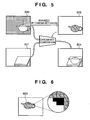
Fig. 5 illustrates chroma key composition processing executed by a chromakey composition unit 1100; -
Fig. 6 is a view showing an example in which noise is superposed on a CG image (may be either a right- or left-eye CG image) since image information in that CG image is lost; -
Fig. 7 is a view for explaining correction of an error part; -
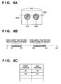
Figs. 8A to 8C are views for explaining processing for specifying non-chroma key regions on lines upon referring to identical lines of right- and left-eye mask images; -
Fig. 9 is a view showing a method of obtaining a tangent on a contour; -
Fig. 10A is a view showing processing for searching for a non-chroma key region in the immediately preceding line toward the inner side of the non-chroma key region when positions immediately above the end points of a non-chroma key region do not belong to a non-chroma key region; -
Fig. 10B is a view showing processing for searching for the end points of a non-chroma key region in the immediately preceding line toward the outer side of the non-chroma key region when positions immediately above the end points of the non-chroma key region belong to a non-chroma key region; -
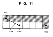
Fig. 11 is a view for explaining processing for correcting a line of the start position which is registered in an n-th row of a left-eye table; -
Fig. 12 is a view for explaining the disparity between the right-eye CG image and left-eye mask image; -
Fig. 13 is a view for explaining processing for correcting a mask image based on the disparity; -
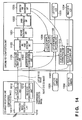
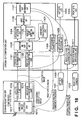
Fig. 14 is a block diagram showing the functional arrangement of anHMD 1000 according to the fourth embodiment; -
Fig. 15 is a view for explaining correction processing of a mask image; -
Fig. 16 is a view for explaining similarities between images of neighboring frames; -
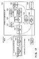
Fig. 17 is a block diagram showing the functional arrangement of a left-eye part of an HMD 1000 according to the third embodiment of the present invention; -
Fig. 18 is a block diagram showing the functional arrangement of anHMD 1000 according to the fourth embodiment of the present invention; -
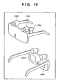
Fig. 19 shows an example of the outer appearance of an HMD 1000 according to the fifth embodiment of the present invention; -
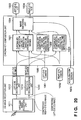
Fig. 20 is a block diagram showing the functional arrangement of the HMD 1000 according to the fifth embodiment of the present invention; -
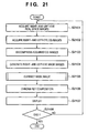
Fig. 21 is a flowchart of the main processing executed when the HMD 1000 presents images obtained by chroma-key compositing real space images and CG images to the right and left eyes of auser 2000; and -
Fig. 22 is a flowchart showing details of the processing in step S2105. - Preferred embodiments of the present invention will now be described in detail with reference to the accompanying drawings. Note that these embodiments will be described as examples of preferred arrangements of the invention described in the scope of claims, and such invention is not limited to the embodiments to be described hereinafter.
- A CG (Computer Graphics) image (virtual space image) used in this embodiment includes a region defined by a pixel group having a chroma key color which is set in advance. In this embodiment, an image formed by chroma-key compositing a CG image (virtual space image) generated to be presented to the right eye of a user and a real space image is presented to the right eye of this user. Furthermore, an image formed by chroma-key compositing a CG image (virtual space image) generated to be presented to the left eye and a real space image is presented to the left eye of this user.
- This embodiment is characterized by the following configuration under the precondition of the above configuration. That is, even when an error part is generated at a boundary between a chroma key region and non-chroma key region in a CG image generated to be presented to one eye during chroma key processing, satisfactory chroma key composition results are presented to the respective eyes by using the nature that CG images to be presented to the respective eyes are similar to each other.
-
Fig. 1 shows a state in which a user uses a system according to this embodiment. The configuration itself of this system is a known MR (Mixed Reality) system. - Referring to
Fig. 1 ,reference numeral 1000 denotes a video see-through type HMD (Head Mounted Display) which serves as an image processing apparatus, and can comprise a known head mounted type display device.Reference numeral 2000 denotes a user who wears theHMD 1000 on the head. The detailed arrangement of theHMD 1000 will be described later. TheHMD 1000 has a screen used to present an image to the right eye of theuser 2000, and that used to present an image to the left eye. Therefore, theuser 2000 can view images corresponding to the respective eyes in front of the eyes by observing the respective screens with the right and left eyes. -
Reference numeral 3000 denotes a computer, which generates a CG image to be presented to the right eye of the user 2000 (right-eye CG image), and a CG image to be presented to the left eye. Thecomputer 3000 wirelessly transmits the respective generated CG images to theHMD 1000. Before transmitting the CG images, thecomputer 3000 compresses the CG images to be transmitted so as to reduce the wireless communication band. TheHMD 1000 uses the compressed CG images after it decompresses them. - When the
computer 3000 wirelessly transmits the compressed right- and left-eye CG images to theHMD 1000, and theHMD 1000 receives and handles these CG images, noise may be superposed on the CG images to be handled (image information may also be lost). This is caused by wireless transmission of the CG images, and decompression of the compressed CG images, as described above. Especially, each CG image includes a chroma key region, as described above. Therefore, when noise is generated at a boundary between a chroma key region and non-chroma key region (an error part is generated at the boundary), even when this CG image is chroma-key composited to a real space image, noise is also generated in the composition result at the boundary. - In this embodiment, by using the nature that right- and left-eye CG images are similar images, even when an error part is generated at the boundary between a chroma key region and non-chroma key region in one CG image, the error part is corrected using the other CG image. In this way, a satisfactory chroma key composition result is obtained.
-
Fig. 3 is a view for explaining general chroma key composition processing. Referring toFig. 3 ,reference numeral 300 denotes a real space image.Reference numeral 301 denotes a CG image, the hatched portion of which indicates a chroma key region.Reference numeral 302 denotes an image (composite image) formed by chroma-key compositing theCG image 301 andreal space image 300. That is, thecomposite image 302 is formed by setting the chroma key region to be transparent upon composition when theCG image 301 is superimposed on thereal space image 300. -
Fig. 4 is a block diagram showing the functional arrangement of theHMD 1000. As shown inFig. 4 , theHMD 1000 comprises a CGimage reception unit 1010, left-eye camera 1001, right-eye camera 1002, chromakey composition unit 1100, left-eye LCD (liquid crystal display) 1003, and right-eye LCD 1004. -
Fig. 2 shows an example of the outer appearance of theHMD 1000. As shown inFig. 2 , the right- and left-eye cameras eye LCDs eye cameras key composition unit 1100 shown inFig. 4 . - Of the arrangement of the
HMD 1000 shown inFig. 4 , the CGimage reception unit 1010 will be described first. - As shown in
Fig. 4 , the CGimage reception unit 1010 comprises a wirelessimage reception unit 1011, left-eye decompression unit 1012, and right-eye decompression unit 1013. - The right- and left-eye CG images (compressed) wirelessly transmitted from the computer 3000 (external apparatus) are received by the wireless
image reception unit 1011. The wirelessimage reception unit 1011 transfers the received right- and left-eye CG images to the right- and left-eye decompression units - As described above, noise due to the wireless communication is likely to be superposed on the right- and left-eye CG images received by the wireless
image reception unit 1011. When the received information is lost due to the wireless communication, the wirelessimage reception unit 1011 interpolates such loss by known techniques. Hence, the CG images transmitted from thecomputer 3000 and those output from the wirelessimage reception unit 1011 may have an unintended difference. - The left-
eye decompression unit 1012 decompresses the compressed left-eye CG image, and outputs the decompressed left-eye CG image to a subsequent left-eyecolor discrimination unit 1101 and left-eyeimage switching unit 1109. Likewise, the right-eye decompression unit 1013 decompresses the compressed right-eye CG image, and outputs the decompressed right-eye CG image to a subsequent right-eyecolor discrimination unit 1102 and right-eyeimage switching unit 1111. - As described above, noise due to image decompression is likely to be superposed on the CG images decompressed by the right- and left-
eye decompression units - The chroma
key composition unit 1100 will be described next. As shown inFig. 4 , the chromakey composition unit 1100 comprises the left-eyecolor discrimination unit 1101, the right-eyecolor discrimination unit 1102, a correspondingpoint detection unit 1103, a left-eyeslope detection unit 1104, a right-eyeslope detection unit 1105, anerror discrimination unit 1106, and a correctionpart discrimination unit 1107. Furthermore, the chromakey composition unit 1100 comprises a left-eyemask correction unit 1108, the left-eyeimage switching unit 1109, a right-eyemask correction unit 1110, and the right-eyeimage switching unit 1111. - The basic operation of the chroma
key composition unit 1100, i.e., the operation of the chromakey composition unit 1100 when theunit 1100 executes conventional chroma key composition processing regardless of noise on the CG images, will be described first with reference toFigs. 4 and5. Fig. 5 shows the chroma key composition processing executed by the chromakey composition unit 1100. - The decompressed left-eye CG image output from the left-
eye decompression unit 1012 is output to the left-eyecolor discrimination unit 1101 and left-eyeimage switching unit 1109, as described above. - The left-eye
color discrimination unit 1101 refers to pixel values of pixels which form the decompressed left-eye CG image, and checks if each referred pixel value indicates a chroma key color which is set in advance. The left-eyecolor discrimination unit 1101 assigns a bit "1" to a pixel having a pixel value which indicates the chroma key color, and a bit "0" to a pixel having a pixel value that does not indicate the chroma key color. - For example, when a pixel value is defined by 8 bits, the chroma key color may be specified by R = 0, G = 0, and B > 250. In this case, the left-eye
color discrimination unit 1101 assigns a bit "1" to a pixel having a pixel value which satisfies R = 0, G = 0, and B > 250, and a bit "0" to a pixel having a pixel value which does not satisfy this condition, of pixels which form the left-eye CG image. That is, the left-eyecolor discrimination unit 1101 generates a binary image in which the pixel values of pixels within a chroma key region in the left-eye CG image are substituted by "1", and those of pixels outside the chroma key region are substituted by "0". This binary image will be referred to as a "mask image" hereinafter. Note that this mask image need not to be stored for one frame, and suffices to be stored as a selection image in a buffer for several lines required for processing. - Referring to
Fig. 5 ,reference numeral 500 denotes a CG image, the hatched portion of which is a chroma key region. Therefore, in this case, a bit "1" is assigned to each of pixels which form the hatched portion, and a bit "0" is assigned to each of pixels which form a portion other than the hatched portion.Reference numeral 503 denotes a mask image formed by a set of such bits. - On the other hand, since the right-eye
color discrimination unit 1102 receives the decompressed right-eye CG image output from the right-eye decompression unit 1013, the right-eyecolor discrimination unit 1102 executes the same processing as in the left-eyecolor discrimination unit 1101, and generates a mask image corresponding to the right-eye CG image. - The mask image generated by the left-eye
color discrimination unit 1101 is input to the correspondingpoint detection unit 1103 and left-eyemask correction unit 1108, and the mask image generated by the right-eyecolor discrimination unit 1102 is input to the correspondingpoint detection unit 1103 and right-eyemask correction unit 1110. In this case, assume that the right- and left-eyemask correction units mask correction unit 1108 outputs the received mask image to the left-eyeimage switching unit 1109 intact, and the right-eyemask correction unit 1110 outputs the received mask image to the right-eyeimage switching unit 1111 intact. - On the other hand, the left-
eye camera 1001 is used to capture a movie of the real space to be presented to the left eye of theuser 2000, and images (real space images) of the captured frames are sequentially input to the left-eyeimage switching unit 1109, as described above. Also, the right-eye camera 1002 is used to capture a movie of the real space to be presented to the right eye of theuser 2000, and images (real space images) of the captured frames are sequentially input to the right-eyeimage switching unit 1111, as described above. InFig. 5 ,reference numeral 501 denotes a real space image captured by the camera. - The left-eye
image switching unit 1109 executes a chroma key composition of the left-eye CG image received from the left-eye decompression unit 1012 and the real space image received from the left-eye camera 1001 using the mask image received from the left-eyecolor discrimination unit 1101. That is, the left-eyeimage switching unit 1109 decides whether to use, as an x-th (1 ≤ x ≤ X) pixel of a composite image to be generated by the chroma key composition, an x-th pixel of the left-eye CG image or that of the real space image, based on the bit value of the x-th pixel in the mask image. Note that X is the total number of pixels of the left-eye CG image (the same applies to the right-eye CG image and composite image). - When the bit value of the x-th pixel in the mask image is "1", the left-eye
image switching unit 1109 uses the x-th pixel in the real space image as that in the composite image. On the other hand, when the bit value of the x-th pixel in the mask image is "0", the left-eyeimage switching unit 1109 uses the x-th pixel in the left-eye CG image as that in the composite image. In this way, the left-eyeimage switching unit 1109 selects pixels selectively from the left-eye CG image and real space image in accordance with the bit values that form the mask image to decide pixels of the composite image, thus generating the composite image. Since such chroma key composition processing is known to those who are skilled in the art, no more explanation will be given. - In
Fig. 5 ,reference numeral 504 denotes a composite image generated by the chroma key composition. - The right-eye
image switching unit 1111 executes the same processing as the left-eyeimage switching unit 1109. That is, the right-eyeimage switching unit 1111 executes the chroma key composition of the right-eye CG image received from the right-eye decompression unit 1013 and the real space image received from the right-eye camera 1002 using the mask image received from the right-eyecolor discrimination unit 1102. - The composite image generated by the left-eye
image switching unit 1109 is output to the left-eye LCD 1003, and the composite image generated by the right-eyeimage switching unit 1111 is output to the right-eye LCD 1004. In this way, the composite images corresponding to the right and left eyes are displayed in front of the right and left eyes of theuser 2000. The composite image is generated by substituting the chroma key region in the CG image by a corresponding region in the real space image for the right and left eyes. - The operation of the chroma
key composition unit 1100 for obtaining satisfactory chroma key composition results even when an error part is generated at the boundary between the chroma key region and non-chroma key region using the nature that the right- and left-eye CG images are similar images will be described next. -
Fig. 6 shows an example in which noise is superposed on a CG image due to a loss of image information in the CG image (which may be either the right- or left-eye CG image). As shown inFig. 6 , by enlarging a region of a part of a handle of atea pot 600 in the CG image, it is found that image information in a portion (black portion) of the chroma key region is lost, and the pixel value of each pixel which forms the lost portion does not satisfy R = 0, G = 0, and B > 250. That is, this portion is no longer the chroma key region. - Therefore, upon executing the chroma key composition of this CG image and real space image, the pixel values of the CG image are left in this black portion intact as noise (error part) on the composite image. This embodiment has as its object to obtain a satisfactory chroma key composition result by correcting this error part. More specifically, the right- and left-eye CG images are compared, and if one CG image includes an error part, this error part is corrected using the other CG image.
- The correction method of an error part according to this embodiment will be briefly described below.
Fig. 7 is a view for explaining correction of an error part. Referring toFig. 7 ,reference numeral 790 denotes a portion (pixel group) of a non-chroma key region which has a common boundary with a chroma key region in a mask image (left-eye mask image) generated from a left-eye CG image.Reference numeral 780 denotes a portion (pixel group) of a non-chroma key region which has a common boundary with a chroma key region in a mask image (right-eye mask image) generated from a right-eye CG image. A pixel group indicated by hatching in thepixel group 780 corresponds to an error part. - Initially, a slope (that of a line 700) of the boundary at a
pixel 720, which is in contact with the chroma key region, of thepixel group 790 is calculated. Also, a slope (that of a line 701) of the boundary at a pixel, the position of which corresponds to the pixel 720 (corresponding pixel), in thepixel group 780 is calculated. Since the right- and left-eye CG images are similar images, it is naturally considered that the respective slopes should be nearly equal to each other. Therefore, if these slopes have a large difference, it is naturally considered that the one of the right- and left-eye CG images includes an error part. - Furthermore, in order to discriminate the right- or left-eye CG image that includes an error part, the slopes calculated for one or more pixels selected before the
pixel 720 as those, which are in contact with the chroma key region, of thepixel group 790 are referred to. Then, some differences, i.e., a difference between the slope calculated for thepixel 720 and that calculated for a pixel selected immediately before thepixel 720, a difference between the slope calculated for thepixel 720 and that calculated for a pixel selected two pixels before thepixel 720, and the like, are calculated. It is checked if a change in the difference is equal to or larger than a predetermined change. - Likewise, the slopes calculated for one or more pixels selected before the corresponding pixel as those which are in contact with the chroma key region of the
pixel group 780 are referred to. Then, some differences, i.e., a difference between the slope calculated for the corresponding pixel and that calculated for a pixel selected immediately before the corresponding pixel, a difference between the slope calculated for the corresponding pixel and that calculated for a pixel selected two pixels before the corresponding pixel, and the like, are calculated. It is checked if a change in the difference is equal to or larger than a predetermined change. - Then, it is determined that one of the
pixel groups Fig. 7 , thepixel group 780 side includes an error part. Therefore, the error part is corrected so that the slope at the corresponding pixel equals that of theline 700. - This processing will be described in more detail below. Note that the operation to be described is executed in addition to the basic operation.
- The corresponding
point detection unit 1103 receives the right- and left-eye mask images output from the right- and left-eyecolor discrimination units point detection unit 1103 then specifies pixel positions (corresponding positions) on the other mask image, the positions of which correspond to respective pixels that form a portion which have a common boundary with a chroma key region (a region with a bit value "1"), in a non-chroma key region (a region with a bit value "0") on one mask image. Various methods have been proposed for the pixel position specifying processing executed by the correspondingpoint detection unit 1103, and this method may adopt any of these methods. For example, a method to be described below may be used. - Initially, the following assumptions are made.
- •The right- and left-
eye cameras - •A region (i.e., a virtual object image) other than the chroma key region in the CG image does not cover the edges of a frame.
- Using such assumptions as a precondition, corresponding pixels can be detected by only comparing the right- and left-eye mask images for respective lines.
- Upon reception of the right- and left-eye mask images, the corresponding
point detection unit 1103 refers to identical lines on the respective mask images, and specifies non-chroma key regions on these lines. -
Figs. 8A to 8C are views for explaining the processing for specifying non-chroma key regions on lines upon referring to identical lines on the right- and left-eye mask images. Note that the processing to be described below usingFigs. 8A to 8C is the same for either the right- or left-eye mask image. Hence, the following description will be given taking the right-eye mask image as an example. -
Fig. 8A shows an example of a right-eye mask image 800. InFig. 8A , the right-eye mask image 800 has a horizontal size of 640 pixels. In the right-eye mask image 800,reference numerals - Upon processing a
line 830 in the right-eye mask image 800, the correspondingpoint detection unit 1103 refers to pixels which define theline 830 in turn from one side. Then, the correspondingpoint detection unit 1103 detects the start and end positions of a non-chroma key region (those of a pixel sequence in which pixels with a pixel value "0" are continuously arranged). -
Fig. 8B shows the distribution of pixels which define theline 830. As shown inFig. 8B , pixel groups which define non-chroma key regions are distributed at x = 60 to 180 and 340 to 500. Therefore, as shown inFig. 8C , on theline 830, the correspondingpoint detection unit 1103 registers "60" in the column of the start position, and "180" in the column of the corresponding end position, so as to indicate existence of a non-chroma key region at x = 60 to 180. Likewise, the correspondingpoint detection unit 1103 registers "340" in the column of the start position, and "500" in the column of the corresponding end position, so as to indicate existence of another non-chroma key region at x = 340 to 500. - In this way, the corresponding
point detection unit 1103 registers sets of the start and end positions for respective non-chroma key regions. Since such table is generated for each line, if the number of lines of the right-eye mask image 800 is 480, 480 tables are generated. However, upon sequentially processing lines, only a table of the line which is being currently processed needs to be held, and the number of tables which are required in practice can be reduced. - Note that the start and end positions are registered in the form of a table in
Fig. 8C . However, the data management format is not limited to this. - As described above, the corresponding
point detection unit 1103 also executes the above processing for the left-eye mask image, and consequently generates a table shown inFig. 8C for the left-eye mask image also. Note that each table generated for the right-eye mask image will be referred to as a right-eye table, and that generated for the left-eye mask image will be referred to as a left-eye table. - In this case, note that a non-chroma key region specified by the start and end positions registered in the m-th (m ≥ 1) row in the right-eye table corresponds to that specified by the start and end positions registered in the m-th row in the left-eye table. The corresponding
point detection unit 1103 outputs the start and end positions registered in the m-th row of the left-eye table to the left-eyeslope detection unit 1104, and those registered in the m-th row of the right-eye table to the right-eyeslope detection unit 1105. - A case will be described below wherein m = n.
- Upon reception of the start and end position registered in the n-th row of the left-eye table, the left-eye
slope detection unit 1104 calculates the slope of the boundary between the chroma key region and non-chroma key region at the start and end positions. Details of the processing executed by the left-eyeslope detection unit 1104 will be described below with reference toFig. 9 . -
Fig. 9 shows pixels which define a non-chroma key region (hatched portion) and those which define a chroma key region. Referring toFig. 9 ,reference numeral 900 denotes a pixel position specified by the start position registered in the n-th row of the left-eye table.Reference numeral 901 denotes a pixel at a position immediately before a position with a referred pixel value "1", upon referring to pixel values from a position one line above, which has the same x-coordinate value as thepixel 900, in a direction to decrease the x-coordinate value.Reference numeral 902 denotes a pixel at a position immediately before a position with a referred pixel value "1", upon referring to pixel values from a position two lines above, which has the same x-coordinate value as thepixel 900, in the direction to decrease the x-coordinate value. - In order to calculate a slope at the position of the
pixel 900, the left-eyeslope detection unit 1104 calculates a slope of a straight line which passes through the position of thepixel 900 and that of thepixel 901, and also a slope of a straight line which passes through the position of thepixel 900 and that of thepixel 902. Then, the left-eyeslope detection unit 1104 calculates the average values of these slopes, and defines the calculated average value as a slope at the position of thepixel 900. In this manner, the left-eyeslope detection unit 1104 can calculate the slope at the start position. - The processing for calculating a slope at the end position will be described below. The left-eye
slope detection unit 1104 specifies a pixel (pixel Q) at a position immediately before a position with a referred pixel value "1", upon referring to pixel values from a position one line above, which has the same x-coordinate value as a pixel (pixel P) specified by the end position registered in the n-th row of the left-eye table, in a direction to increase the x-coordinate value. Then, the left-eyeslope detection unit 1104 specifies a pixel (pixel R) at a position immediately before a position with a referred pixel value "1", upon referring to pixel values from a position two line above, which has the same x-coordinate value as the pixel P, in the direction to increase the x-coordinate value. The left-eyeslope detection unit 1104 calculates a slope of a straight line which passes through the position of the pixel P and that of the pixel Q, and also a slope of a straight line which passes through the position of the pixel P and that of the pixel R. The left-eyeslope detection unit 1104 then calculates the average value of these slopes, and defines the calculated average value as a slope at the position of the pixel P. - A method of specifying two pixels obtained from the start position (e.g., the
pixels Fig. 9 ) and those obtained from the end position (e.g., the pixels Q and R) will be described below with reference toFigs. 10A and 10B . -
Fig. 10A shows a case in which both a position one line above, which has the same x-coordinate value as a pixel position specified by the start position registered in the n-th row of the left-eye table, and a position one line above, which the same x-coordinate value as a pixel position specified by the end position are within a chroma key region. InFig. 10A ,reference numeral 1091 denotes a pixel position specified by the start position registered in the n-th row of the left-eye table; and 1093, a pixel position specified by the end position registered in the n-th row of the left-eye table. -
Fig. 10B shows a case in which both a position one line above, which has the same x-coordinate value as a pixel position specified by the start position registered in the n-th row of the left-eye table, and a position one line above, which the same x-coordinate value as a pixel position specified by the end position are within a non-chroma key region. InFig. 10B ,reference numeral 1081 denotes a pixel position specified by the start position registered in the n-th row of the left-eye table; and 1083, a pixel position specified by the end position registered in the n-th row of the left-eye table. - The left-eye
slope detection unit 1104 checks if a pixel value of a pixel at a position one line above, which has the same x-coordinate value as a pixel position specified by the start position registered in the n-th row of the left-eye table in the left-eye mask image is "1" or "0". As a result of checking, if the pixel value is "1", i.e., if the pixel at the position one line above, which has the same x-coordinate value as a pixel position specified by the start position registered in the n-th row of the left-eye table, is included in a chroma key region, the left-eyeslope detection unit 1104 executes the following processing. That is, as shown inFig. 10A , the left-eyeslope detection unit 1104 refers to pixel values from a position one line above, which has the same x-coordinate value as thepixel position 1091, in the direction to increase the x-coordinate value. Then, the left-eyeslope detection unit 1104 specifies a pixel at afirst position 1092 where the referred pixel value becomes "0" as "pixel S1". On the other hand, as a result of checking, if the pixel value is "0", i.e., if the pixel at the position one line above, which has the same x-coordinate value as a pixel position specified by the start position registered in the n-th row of the left-eye table, is included in a non-chroma key region, the left-eyeslope detection unit 1104 executes the following processing. That is, as shown inFig. 10B , the left-eyeslope detection unit 1104 refers to pixel values from a position one line above, which has the same x-coordinate value as thepixel position 1081, in the direction to decrease the x-coordinate value. Then, the left-eyeslope detection unit 1104 specifies a pixel at aposition 1082 immediately before the referred pixel value becomes "1" as "pixel S1". - Next, the left-eye
slope detection unit 1104 checks if a pixel value of a pixel at a position one line above, which has the same x-coordinate value as a pixel position specified by the end position registered in the n-th row of the left-eye table in the left-eye mask image is "1" or "0". As a result of checking, if the pixel value is "1", i.e., if the pixel at the position one line above, which has the same x-coordinate value as a pixel position specified by the end position registered in the n-th row of the left-eye table, is included in a chroma key region, the left-eyeslope detection unit 1104 executes the following processing. That is, as shown inFig. 10A , the left-eyeslope detection unit 1104 specifies a pixel at afirst position 1094 where a referred pixel value becomes "0" as "pixel E1" upon referring to pixel values from a position one line above, which has the same x-coordinate value as thepixel position 1093, in the direction to decrease the x-coordinate value. On the other hand, as a result of checking, if the pixel value is "0", i.e., if the pixel at the position one line above, which has the same x-coordinate value as a pixel position specified by the end position registered in the n-th row of the left-eye table, is included in a non-chroma key region, the left-eyeslope detection unit 1104 executes the following processing. That is, as shown inFig. 10B , the left-eyeslope detection unit 1104 specifies a pixel at aposition 1084 immediately before a referred pixel value becomes "1" as "pixel E1" upon referring to pixel values from a position one line above, which has the same x-coordinate value as thepixel position 1083, in the direction to increase the x-coordinate value. - Likewise, the left-eye
slope detection unit 1104 refers to pixel values in a direction to decrease or increase the x-coordinate value depending on whether the pixel value of a pixel one line above, which has the same x-coordinate value as the pixel S1, is "1" or "0". Then, the left-eyeslope detection unit 1104 similarly specifies a pixel S2. Also, the left-eyeslope detection unit 1104 refers to pixel values in a direction to decrease or increase the x-coordinate value depending on whether the pixel value of a pixel one line above, which has the same x-coordinate value as the pixel E1, is "1" or "0". Then, the left-eyeslope detection unit 1104 similarly specifies a pixel E2. - The left-eye
slope detection unit 1104 then calculates a slope VSL1 of a straight line which passes through the pixel specified by the start position registered in the n-th row of the left-eye table, and the pixel S1. Furthermore, the left-eyeslope detection unit 1104 calculates a slope VSL2 of a straight line which passes through the pixel specified by the start position registered in the n-th row of the left-eye table, and the pixel S2. Then, the left-eyeslope detection unit 1104 calculates an average value VSL3 of the slopes VSL1 and VSL2 as a slope of the boundary between the chroma key region and non-chroma key region at the start position (position of interest) registered in the n-th row of the left-eye table. - Likewise, the left-eye
slope detection unit 1104 then calculates a slope VEL1 of a straight line which passes through the pixel specified by the end position registered in the n-th row of the left-eye table, and the pixel E1. Furthermore, the left-eyeslope detection unit 1104 calculates a slope VEL2 of a straight line which passes through the pixel specified by the end position registered in the n-th row of the left-eye table, and the pixel E2. Then, the left-eyeslope detection unit 1104 calculates an average value VEL3 of the slopes VEL1 and VEL2 as a slope of the boundary between the chroma key region and non-chroma key region at the end position registered in the n-th row of the left-eye table. - The left-eye
slope detection unit 1104 then outputs VSL1 to VSL3 and VEL1 to VEL3 to theerror discrimination unit 1106. - The right-eye
slope detection unit 1105 executes the same processing as in the left-eyeslope detection unit 1104, and calculates slopes VSR1 to VSR3 corresponding to the slopes VSL1 to VSL3, and slopes VER1 to VER3 corresponding to the slopes VEL1 to VEL3 from the right-eye mask image. The right-eyeslope detection unit 1105 outputs the calculated slopes VSR1 to VSR3 and slopes VER1 to VER3 to theerror discrimination unit 1106. - The
error discrimination unit 1106 checks if the difference between the slopes VSL3 and VSR3 is equal to or larger than a threshold (for example, 10° in this case). As a result of checking, if the difference is equal to or larger than 10°, theerror discrimination unit 1106 determines that one of the right- and left-eye CG images includes an error part. On the other hand, if the difference between the slopes VSL3 and VSR3 is smaller than the threshold, theerror discrimination unit 1106 determines that the neither the left-eye CG image nor the right-eye CG image include an error part. - Of course, the criterion for checking whether or not one of the right- and left-eye CG images includes an error part is not limited to such specific criterion, and various other criteria may be used. When other criteria are used, information to be calculated for such criteria needs to be calculated as needed.
- The
error discrimination unit 1106 outputs VSL1 to VSL3 and VSR1 to VSR3 to the correctionpart discrimination unit 1107 together with flag information indicating whether or not one of the right- and left-eye CG images includes an error part. - The correction
part discrimination unit 1107 checks with reference to this flag information which of the right- and left-eye CG images includes an error part. In this embodiment, when the boundary between the chroma key region and non-chroma key region is considered as a curve (including a straight line), it is determined that an image having a smooth curve shape is free from any error part. Of course, such criterion is only an example, and other criteria may be used. - The correction
part discrimination unit 1107 according to this embodiment refers to the flag value received from theerror discrimination unit 1106. If this flag value indicates that "no error part is included", the correctionpart discrimination unit 1107 does not execute any processing. - On the other hand, if the flag value received from the
error discrimination unit 1106 indicates that "an error part is included", the correctionpart discrimination unit 1107 calculates an angle the slopes VSL1 and VSL2 make, and also an angle the slopes VSR1 and VSR2 make. The correctionpart discrimination unit 1107 determines that the mask image with a larger one of the calculated angles includes an error part. As a result, if the correctionpart discrimination unit 1107 determines that the left-eye mask image includes an error part, it outputs the slope VSR1 (or VSR2) to the left-eyemask correction unit 1108. On the other hand, if the correctionpart discrimination unit 1107 determines that the right-eye mask image includes an error part, it outputs the slope VSL1 (or VSL2) to the right-eyemask correction unit 1110. - Upon reception of the slope VSR1 from the correction
part discrimination unit 1107, the left-eyemask correction unit 1108 specifies a pixel (correction start pixel), through which a straight line that passes through the pixel S1 and has the slope VSR1 passes, of a pixel group on a line immediately below the line of the pixel S1. When the x-coordinate value of the correction start pixel is smaller than that of the start position registered in the n-th row of the left-eye table, the left-eyemask correction unit 1108 sets the pixel values of the correction start pixel, and of those between the correction start pixel and the pixel of the start position registered in the n-th row of the left-eye table, to be "0". On the other hand, when the x-coordinate value of the correction start pixel is larger than that of the start position registered in the n-th row of the left-eye table, the left-eyemask correction unit 1108 sets the pixel values of the pixel of the start position registered in the n-th row of the left-eye table, and of those between this pixel and the correction start pixel, to be "1". -
Fig. 11 is a view for explaining the processing for correcting a line of the start position registered in the n-th row of the left-eye table. Referring toFig. 11 ,reference numeral 1192 denotes a pixel S1; and 1199, a pixel specified by the start position registered in the n-th row of the left-eye table.Reference numeral 1198 denotes a correction start pixel. As described above, a pixel, through which a straight line that passes through thepixel 1192 and has the slope VSR1 passes, of those which define the line of the start position registered in the n-th row of the left-eye table, is thecorrection start pixel 1198. Therefore, in this case, the left-eyemask correction unit 1108 sets the pixel values of pixels between thecorrection start pixel 1198 and a pixel 1199 (including the correction start pixel 1198) to be "0". - The
error discrimination unit 1106 checks if the difference between the slopes VEL3 and VER3 is equal to or larger than 10°. As a result of checking, if the difference is equal to or larger than 10°, theerror discrimination unit 1106 determines that one of the right- and left-eye CG images includes an error part. Of course, the criterion for checking whether or not one of the right- and left-eye CG images includes an error part is not limited to such a specific criterion, and various other criteria may be used. When other criteria are used, information to be calculated for such criteria needs to be calculated. - The
error discrimination unit 1106 outputs VEL1 to VEL3 and VER1 to VER3 to the correctionpart discrimination unit 1107 together with flag information indicating whether or not one of the right- and left-eye CG images includes an error part. - The correction
part discrimination unit 1107 checks which of the right- and left-eye CG images includes an error part. In this embodiment, when the boundary between the chroma key region and non-chroma key region is considered as a curve (including a straight line), it is determined that an image having a smooth curve shape is free from any error part. Of course, such criterion is an example, and other criteria may be used. - The correction
part discrimination unit 1107 according to this embodiment refers to the flag value received from theerror discrimination unit 1106. If this flag value indicates that "no error part is included", the correctionpart discrimination unit 1107 does not execute any processing. - On the other hand, if the flag value received from the
error discrimination unit 1106 indicates that "an error part is included", the correctionpart discrimination unit 1107 calculates an angle the slopes VEL1 and VEL2 make, and also an angle the slopes VER1 and VER2 make. The correctionpart discrimination unit 1107 determines that the mask image with a larger one of the calculated angles includes an error part. As a result, if the correctionpart discrimination unit 1107 determines that the left-eye mask image includes an error part, it outputs the slope VER1 (or VER2) to the left-eyemask correction unit 1108. On the other hand, if the correctionpart discrimination unit 1107 determines that the right-eye mask image includes an error part, it outputs the slope VEL1 (or VEL2) to the right-eyemask correction unit 1110. - Upon reception of the slope VER1 from the correction
part discrimination unit 1107, the left-eyemask correction unit 1108 specifies a pixel (correction start pixel), through which a straight line that passes through the pixel E1 and has the slope VER1 passes, of a pixel group on a line immediately below the line of the pixel E1. - When the x-coordinate value of the correction start pixel is smaller than that of the end position registered in the n-th row of the left-eye table, the left-eye
mask correction unit 1108 sets the pixel values of the pixel of the end position registered in the n-th row of the left-eye table and of those between this pixel and the correction start pixel, to be "1". On the other hand, when the x-coordinate value of the correction start pixel is larger than that of the end position registered in the n-th row of the left-eye table, the left-eyemask correction unit 1108 sets the pixel values of the correction start pixel, and of those between the correction start pixel and the pixel of the end position registered in the n-th row of the left-eye table, to be "0". - The right-eye
mask correction unit 1110 executes basically the same processing as in the left-mask correction unit 1108, except for the different slopes to be used. - With the aforementioned processing, since an error part in the mask image can be corrected, no error part is generated in the composition result even when the chroma key composition processing is executed using this mask image, as described above.
- Upon completion of the aforementioned processing for all the rows of the right- and left-eye tables, the same processing is repeated for the next line.
- In this embodiment, only the mask image is corrected. However, it is preferable to also correct the CG image in the process of this correction. For example, when pixels whose pixel values are corrected in the left-eye mask image are included in a non-chroma key region as a result of this correction, the pixel values of pixels in the right-eye CG image corresponding to pixels (left pixels) in the left-eye CG image, which correspond to those pixels, are copied to the pixel values of the left pixels.
-
Fig. 21 is a flowchart of the main processing executed when theHMD 1000 presents images obtained by chroma-key compositing the real space images and CG images to the right and left eyes of theuser 2000. - In step S2101, the right- and left-eye
image switching units eye cameras - In step S2102, the wireless
image reception unit 1011 receives (acquires) compressed right- and left-eye CG images. - In step S2103, the right-
eye decompression unit 1013 decompresses the compressed right-eye CG image, and the left-eye decompression unit 1012 decompresses the compressed left-eye CG image. - In step S2104, the left-eye
color discrimination unit 1101 generates a left-eye mask image, and the right-eyecolor discrimination unit 1102 generates a right-eye mask image. - In step S2105, a series of processes associated with correction of the mask images are executed. Details of the processing in step S2105 will be described later.
- In step S2106, the right-eye
image switching unit 1111 executes chroma key composition of the right-eye real space image acquired in step S2101 and the right-eye CG image decompressed in step S2103 using the right-eye mask image. This right-eye mask image is the one which may or may not be corrected by the right-eyemask correction unit 1110. Furthermore, in step S2106 the left-eyeimage switching unit 1109 executes chroma key composition of the left-eye real space image acquired in step S2101 and the left-eye CG image decompressed in step S2103 using the left-eye mask image. This left-eye mask image is the one which may or may not be corrected by the left-eyemask correction unit 1108. - In step S2107, the left-eye
image switching unit 1109 outputs a composite image after the chroma key composition to the left-eye LCD 1003, thus displaying this composite image on the left-eye LCD 1003. Furthermore, in step S2107 the right-eyeimage switching unit 1111 outputs a composite image after the chroma key composition to the right-eye LCD 1004, thus displaying this composite image on the right-eye LCD 1004. - The process returns to step S2101 via step S2108 unless the end condition of this processing is satisfied, and the subsequent processes are repeated for the next frame.
-
Fig. 22 is a flowchart showing details of the processing in step S2105. Since details of the processing according to the flowchart ofFig. 22 have been described above, a brief explanation will be given below. - In step S2201, a variable n used in the following processing is set to be "1". Since this variable n is used to indicate a row to be processed in each of right- and left-eye tables, the corresponding
point detection unit 1103 preferably executes the processing in step S2201. However, the main body of the processing in this step is not limited to the correspondingpoint detection unit 1103. - In step S2202, a variable 1 used in the following processing is set to be "1". Since this
variable 1 is used to indicate a line to be processed of those which form right- and left-eye mask images, the correspondingpoint detection unit 1103 preferably executes the processing in step S2202. However, the main body of the processing in this step is not limited to the correspondingpoint detection unit 1103. - In step S2203, the corresponding
point detection unit 1103 generates a left-eye table for the 1-th line of the left-eye mask image, and also a right-eye table for the 1-th line of the right-eye mask image. - In step S2204, the corresponding
point detection unit 1103 acquires the start and end positions registered in the n-th rows in the right- and left-eye tables. The correspondingpoint detection unit 1103 outputs the start and end positions acquired from the right-eye table to the right-eyeslope detection unit 1105, and those acquired from the left-eye table to the left-eyeslope detection unit 1104. - In step S2205, the left-eye
slope detection unit 1104 executes the aforementioned processing to calculate slopes VSL1 to VSL3 and VEL1 to VEL3. The left-eyeslope detection unit 1104 outputs the calculated slopes VSL1 to VSL3 and VEL1 to VEL3 to theerror discrimination unit 1106. Furthermore, in this step the right-eyeslope detection unit 1105 executes the aforementioned processing to calculate slopes VSR1 to VSR3 and VER1 to VER3. The right-eyeslope detection unit 1105 outputs the calculated slopes VSR1 to VSR3 and VER1 to VER3 to theerror discrimination unit 1106. - The
error discrimination unit 1106 checks in step S2206 if the difference between the slopes VSL3 and VSR3 is equal to or larger than 10°. As a result of checking, if the difference is equal to or larger than 10°, theerror discrimination unit 1106 outputs VSL1 to VSL3 and VSR1 to VSR3 to the correctionpart discrimination unit 1107 together with flag information indicating whether or not one of the right- and left-eye CG images includes an error part. The process then advances to step S2207. On the other hand, if the difference is less than 10°, the process jumps to step S2210. - In step S2207, the correction
part discrimination unit 1107 calculates an angle θ1 the slopes VSL1 and VSL2 make, and also an angle θ2 the slopes VSR1 and VSR2 make. - In step S2219, the correction
part discrimination unit 1107 compares θ1 and θ2. If θ1 >θ 2, the correctionpart discrimination unit 1107 outputs the slope VSR1 (or VSR2) to the left-eyemask correction unit 1108. The process advances to step S2208. On the other hand, if θ1 ≤ θ2, the correctionpart discrimination unit 1107 outputs the slope VSL1 (or VSL2) to the right-eyemask correction unit 1110. The process then advances to step S2209. - In step S2208, the left-eye
mask correction unit 1108 specifies a pixel (correction start pixel), through which a straight line that passes through the pixel S1 and has the slope VSR1 passes, of a pixel group on a line immediately below the line of the pixel S1. If the x-coordinate value of the correction start pixel is smaller than that of the start position registered in the n-th row of the left-eye table, the left-eyemask correction unit 1108 sets the pixel values of the correction start pixel, and of those between the correction start pixel and the pixel of the start position registered in the n-th row of the left-eye table, to be "0". On the other hand, if the x-coordinate value of the correction start pixel is larger than that of the start position registered in the n-th row of the left-eye table, the left-eyemask correction unit 1108 sets the pixel values of the pixel of the start position registered in the n-th row of the left-eye table, and of those between this pixel and the correction start pixel, to be "1". In this way, the left-eye mask image is corrected in step S2208. - On the other hand, in step S2209, the right-eye
mask correction unit 1110 executes basically the same processing as in the left-mask correction unit 1108 except for the different slopes to be used. In this way, the right-eye mask image is corrected. - The
error discrimination unit 1106 checks in step S2210 if the difference between the slopes VEL3 and VER3 is equal to or larger than 10°. As a result of checking, if the difference is equal to or larger than 10°, theerror discrimination unit 1106 outputs VEL1 to VEL3 and VER1 to VER3 to the correctionpart discrimination unit 1107 together with flag information indicating whether or not one of the right- and left-eye CG images includes an error part. The process then advances to step S2211. On the other hand, if the difference is less than 10°, the process jumps to step S2215. - In step S2211, the correction
part discrimination unit 1107 calculates an angle θ3 the slopes VEL1 and VEL2 make, and also an angle θ4 the slopes VER1 and VER2 make. - In step S2212, the correction
part discrimination unit 1107 compares θ3 and θ4. If θ3 > θ 4, the correctionpart discrimination unit 1107 outputs the slope VER1 (or VER2) to the left-eyemask correction unit 1108. The process then advances to step S2213. On the other hand, if θ3 ≤ θ4, correctionpart discrimination unit 1107 outputs the slope VEL1 (or VEL2) to the right-eyemask correction unit 1110. The process then advances to step S2214. - In step S2213, the left-eye
mask correction unit 1108 specifies a pixel (correction start pixel), through which a straight line that passes through the pixel E1 and has the slope VER1 passes, of a pixel group on a line immediately below the line of the pixel E1. If the x-coordinate value of the correction start pixel is smaller than that of the end position registered in the n-th row of the left-eye table, the left-eyemask correction unit 1108 sets the pixel values of the pixel of the end position registered in the n-th row of the left-eye table and of those between this pixel and the correction start pixel, to be "1". On the other hand, if the x-coordinate value of the correction start pixel is larger than that of the end position registered in the n-th row of the left-eye table, the left-eyemask correction unit 1108 sets the pixel values of the correction start pixel, and of those between the correction start pixel and the pixel of the end position registered in the n-th row of the left-eye table, to be "0". In this manner, the left-eye mask image is corrected in step S2213. - In step S2214, the right-eye
mask correction unit 1110 executes basically the same processing as in the left-eyemask correction unit 1108 except for the different slopes to be used. In this way, the right-eye mask image is corrected. - The corresponding
point detection unit 1103 checks in step S2215 if n = N (N is the total number of rows in each of the right- and left-eye tables), i.e., if the processes in step S2204 and subsequent steps are complete for all the rows in the right- and left-eye tables. As a result of checking, if n = N, the process advances to step S2217. On the other hand, if n < N, the process advances to step S2216. - In step S2216, the corresponding
point detection unit 1103 increments the value of the variable n by one. Then, the processes in steps S2204 and subsequent steps are repeated. - On the other hand, the corresponding
point detection unit 1103 checks in step S2217 if 1 = L (L is the total number of lines of each of the right- and left-eye mask images), i.e., if the processes in step S2203 and subsequent steps are complete for all the lines of the right- and left-eye images. As a result of checking, if 1 = L, the processing according to the flowchart shown inFig. 22 ends, and the control returns to step S2106. On the other hand, if 1 < L, the process advances to step S2218. - In step S2218, the corresponding
point detection unit 1103 increments the value of the variable 1 by one. Then, the processes in step S2203 and subsequent steps are repeated. - As described above, according to this embodiment, using the similarity between the right and left CG images, even when one CG image includes an error part, the boundary between the chroma key region and non-chroma key region is correctly detected, and the chroma key color required for the chroma key composition can be satisfactorily detected.
- Note that this embodiment implements correction of the chroma key composition by correcting mask images. However, the correction of the chroma key composition need not always be implemented by correcting the mask images. That is, by correcting the CG images including an error part or images obtained as a result of the chroma key composition, the chroma key composition can be implemented by correcting losses from the CG images including an error part.
- Even in the method of directly correcting CG images or the method of correcting images obtained as a result of the chroma key composition, this embodiment can be similarly applied, and can implement the chroma key composition by correcting an error part.
- This embodiment corrects an error part using the disparity between right- and left-eye CG images. Note that various criteria to be described in this embodiment are examples, and can be modified as needed by those who are skilled in the art.
-
Fig. 12 is a view for explaining the disparity between a right-eye CG image and left-eye mask image. InFig. 12 ,reference numeral 12010 denotes a left-eye mask image; and 12020, a right-eye mask image. These mark images include non-chromakey regions Reference numeral 12030 denotes an image obtained when the right- and left-eye mask images image 12030, the positions of the non-chromakey regions eye mask images 1220 and 12010 are slightly different. - In this embodiment, whether or not an error part is included is checked by detecting, for each line, a positional difference between a boundary between a chroma key region and non-chroma key region in the right-eye mask image, and a boundary corresponding to this boundary in the left-eye mask image.
-
Fig. 14 is a block diagram showing the functional arrangement of anHMD 1000 according to this embodiment. Note that the same reference numerals inFig. 14 denote the same parts as those inFig. 4 , and repetitive description will be omitted. - A
disparity calculation unit 1201 receives the start and end positions registered in the n-th row of a left-eye table, and those registered in the n-th row of a right-eye table from a correspondingpoint detection unit 1103. - Then, the
disparity calculation unit 1201 calculates, as a "disparity DSi", a value (positional difference) by subtracting the start position registered in the n-th row of the right-eye table from that registered in the n-th row of the left-eye table. Also, thedisparity calculation unit 1201 calculates pixels S2 and S1 in the right- and left-eye mask images by executing the processing described in the first embodiment. Then, thedisparity calculation unit 1201 calculates, as a "disparity DS(i-1)", a value by subtracting the position of the pixel S1 in the right-eye mask image from that of the pixel S1 in the left-eye mask image. Furthermore, thedisparity calculation unit 1201 calculates, as a "disparity DS (i-2)", a value by subtracting the position of the pixel S2 in the right-eye mask image from that of the pixel S2 in the left-eye mask image. - Also, the
disparity calculation unit 1201 calculates, as a "disparity DEi", a value by subtracting the end position registered in the n-th row of the right-eye table from that registered in the n-th row of the left-eye table. Also, thedisparity calculation unit 1201 calculates pixels E2 and E1 in the right- and left-eye mask images by executing the processing described in the first embodiment. Then, thedisparity calculation unit 1201 calculates, as a "disparity DE(i-1)", a value by subtracting the position of the pixel E1 in the right-eye mask image from that of the pixel E1 in the left-eye mask image. Furthermore, thedisparity calculation unit 1201 calculates, as a "disparity DE(i-2)", a value by subtracting the position of the pixel E2 in the right-eye mask image from that of the pixel E2 in the left-eye mask image. - The
disparity calculation unit 1201 outputs the calculated data of DSi, DS(i-1), DS(i-2), DEi, DE(i-1), and DE(i-2) to a subsequenterror discrimination unit 1202. - The
disparity calculation unit 1201 executes processing which is described in the first embodiment as that to be executed by the right- and left-eyeslope detection units disparity calculation unit 1201 calculates slopes VSL1 to VSL3, VEL1 to VEL3, VSR1 to VSR3, and VER1 to VER3. Thedisparity calculation unit 1201 outputs these calculated slopes to a correctionpart discrimination unit 1203. - The
error discrimination unit 1202 checks based on the received disparity data if one of the right- and left-eye CG images includes an error part. - This embodiment is based on the precondition that the disparities for respective lines change smoothly in the right- and left-eye CG images, as shown in
Fig. 13 . If a disparity changes abruptly in a certain line, it is determined that this line includes an error part.Fig. 13 is a view for explaining processing for correcting mask images based on a disparity. - More specifically, the
error discrimination unit 1202 calculates a difference x between DSi and DS(i-1), and a difference y between DS(i-1) and DS(i-2), and checks if the absolute value of a difference (change amount) between the differences x and y is equal to or larger than 10. If this absolute value is equal to or larger than 10, theerror discrimination unit 1202 determines that one of the right- and left-eye CG images includes an error part. - The
error discrimination unit 1202 generates flag information indicating the determination result as to whether or not an error part is included, and outputs the correctionpart discrimination unit 1203. - The correction
part discrimination unit 1203 refers to the flag information from theerror discrimination unit 1202. If this flag information indicates that "one of the right- and left-eye CG images includes an error part", the correctionpart discrimination unit 1203 checks which of the CG images includes an error part. The correctionpart discrimination unit 1203 executes this checking processing as in the first embodiment. Therefore, the correctionpart discrimination unit 1203 executes the same processing as that executed by the correctionpart discrimination unit 1107 using the data of VSL1 to VSL3 and VSR1 to VSR3 received from thedisparity calculation unit 1201. - When the correction
part discrimination unit 1203 determines that the left-eye mask image includes an error part, it acquires the data of DS(i-1) and DS(i-2) from thedisparity calculation unit 1201. The correctionpart discrimination unit 1203 calculates 2 x DS(i-1) - DS(i-2) using the acquired data, and outputs the calculated value to a left-eyemask correction unit 1208 as corrected disparity data. On the other hand, when the correctionpart discrimination unit 1203 determines that the right-eye mask image includes an error part, it calculates a value of 2 x DS(i-1) - DS(i-2) to a right-eyemask correction unit 1210 as corrected disparity data. - The left-eye
mask correction unit 1208 acquires a start position (p) registered in the n-th row of the right-eye table from the correspondingpoint detection unit 1103, and specifies a correction start pixel at the position of p + 2 x DS(i-1) - DS(i-2) on the left-eye mask image. When the x-coordinate value of the correction start pixel is smaller than that of the start position registered in the n-th row of the left-eye table, the left-eyemask correction unit 1208 sets the pixel values of the correction start pixel, and of those between the correction start pixel and the pixel of the start position registered in the n-th row of the left-eye table, to be "0". On the other hand, when the x-coordinate value of the correction start pixel is larger than that of the start position registered in the n-th row of the left-eye table, the left-eyemask correction unit 1208 sets the pixel values of the pixel of the start position registered in the n-th row of the left-eye table, and of those between this pixel and the correction start pixel, to be "1". - The right-eye
mask correction unit 1210 acquires a start position (p) registered in the n-th row of the left-eye table from the correspondingpoint detection unit 1103, and specifies a correction start pixel at the position of p - 2 x DS(i-1) + DS(i-2) on the left-eye mask image. When the x-coordinate value of the correction start pixel is smaller than that of the start position registered in the n-th row of the right-eye table, the right-eyemask correction unit 1210 sets the pixel values of the correction start pixel, and of those between the correction start pixel and the pixel of the start position registered in the n-th row of the right-eye table, to be "0". On the other hand, when the x-coordinate value of the correction start pixel is larger than that of the start position registered in the n-th row of the right-eye table, the right-eyemask correction unit 1210 sets the pixel values of the pixel of the start position registered in the n-th row of the right-eye table, and of those between this pixel and the correction start pixel, to be "1". - Also, the
error discrimination unit 1202 calculates a difference x between DEi and DE(i-1), and a difference y between DE(i-1) and DE(i-2), and checks if the absolute value of a difference between the differences x and y is equal to or larger than 10. If this absolute value is equal to or larger than 10, theerror discrimination unit 1202 determines that one of the right- and left-eye CG images includes an error part. - The
error discrimination unit 1202 generates flag information indicating the determination result as to whether or not an error part is included, and outputs the correctionpart discrimination unit 1203. - The correction
part discrimination unit 1203 refers to the flag information from theerror discrimination unit 1202. If this flag information indicates that "one of the right- and left-eye CG images includes an error part", the correctionpart discrimination unit 1203 checks which of the CG images includes an error part. The correctionpart discrimination unit 1203 executes this checking processing as in the first embodiment. Therefore, the correctionpart discrimination unit 1203 executes the same processing as that executed by the correctionpart discrimination unit 1107 using the data of VEL1 to VEL3 and VER1 to VER3 received from thedisparity calculation unit 1201. - When the correction
part discrimination unit 1203 determines that the left-eye mask image includes an error part, it acquires the data of DE(i-1) and DE(i-2) from thedisparity calculation unit 1201. The correctionpart discrimination unit 1203 calculates 2 x DE(i-1) - DE(i-2) using the acquired data, and outputs the calculated value to the left-eyemask correction unit 1208 as corrected disparity data. On the other hand, when the correctionpart discrimination unit 1203 determines that the right-eye mask image includes an error part, it calculates a value of 2 x DE(i-1) - DE(i-2) to the right-eyemask correction unit 1210 as corrected disparity data. - The left-eye
mask correction unit 1208 acquires an end position (q) registered in the n-th row of the right-eye table from the correspondingpoint detection unit 1103, and specifies a correction start pixel at the position of q + 2 x DE(i-1) - DE(i-2) on the left-eye mask image, as shown inFig. 15 . When the x-coordinate value of the correction start pixel is smaller than that of the end position registered in the n-th row of the left-eye table, the left-eyemask correction unit 1208 sets the pixel values of the pixel of the end position registered in the n-th row of the left-eye table and of those between this pixel and the correction start pixel, to be "1". On the other hand, when the x-coordinate value of the correction start pixel is larger than that of the end position registered in the n-th row of the left-eye table, the left-eyemask correction unit 1208 sets the pixel values of the correction start pixel, and of those between the correction start pixel and the pixel of the end position registered in the n-th row of the left-eye table, to be "0". - On the other hand, the right-eye
mask correction unit 1210 acquires an end position (q) registered in the n-th row of the left-eye table from the correspondingpoint detection unit 1103, and specifies a correction start pixel at the position of q - 2 x DE(i-1) + DE(i-2) on the right-eye mask image. When the x-coordinate value of the correction start pixel is smaller than that of the end position registered in the n-th row of the right-eye table, the right-eyemask correction unit 1210 sets the pixel values of the pixel of the end position registered in the n-th row of the right-eye table and of those between this pixel and the correction start pixel, to be "1". On the other hand, when the x-coordinate value of the correction start pixel is larger than that of the end position registered in the n-th row of the right-eye table, the right-eyemask correction unit 1210 sets the pixel values of the correction start pixel, and of those between the correction start pixel and the pixel of the end position registered in the n-th row of the right-eye table, to be "0". - In this way, the right- and left-eye mask images are corrected.
- The subsequent processes are the same as those in the first embodiment.
- In the first embodiment, the slopes of the contours of the right and left images are compared to find losses, and these losses are corrected upon execution of chroma key composition. When right and left images having a small disparity are similar to each other, the method of the first embodiment works satisfactorily. However, when right and left images having a relatively large disparity are relatively different from each other, the method of the first embodiment does not always normally work.
- Since this embodiment uses the continuity of disparities, even when right and left contours look different (for example, when an object is present in front of one eye), correction can be done to some extent. In this regard, this embodiment exhibits characteristics superior to the first embodiment.
- However, when objects overlap each other, discontinuity of disparities occurs, and this embodiment does not always work. This embodiment is not suited to handling such images.
- This embodiment implements correction of the chroma key composition by correcting mask images. However, the correction of the chroma key composition need not always be implemented by correcting the mask images.
- By correcting the CG images with losses or images obtained as a result of the chroma key composition, the chroma key composition can be implemented by correcting losses from the input images with losses.
- Even in the method of directly correcting CG images or the method of correcting images obtained as a result of the chroma key composition, this embodiment can be similarly applied, and can implement the chroma key composition by correcting losses.
- In this embodiment, using left-eye CG images of respective frames, an error part in a left-eye CG image of the frame of interest is corrected. Likewise, using right-eye CG images of respective frames, an error part in a right-eye CG image of the frame of interest is corrected.
- In this embodiment, based on the precondition that images of successive (continuous) frames are relatively similar to each other, as shown in
Fig. 16 , it is determined that an image of the frame of interest in which a part largely different from an image of the previous frame includes an error part. Then, a mask image corresponding to the image of the frame of interest is corrected. - In the first and second embodiments, since the presence/absence of an error part is determined using similarities of stereoscopic images, when a nearby object is captured, a largely different part may appear in an image for the right eye, and that for the left eye. Therefore, in such case, satisfactory correction is disturbed.
- This embodiment is free from such restrictions since the presence/absence of an error part is determined using images of successive frames. Even when a nearby object is captured, chroma key composition can be implemented by correcting losses of input images without posing any problem.
- However, images of successive frames are expected to have similarities when the cameras do not make large movements. When the positions and orientations of the cameras are changed, this embodiment cannot always obtain the results better than the correction using similarities of stereoscopic images.
-
Fig. 17 is a block diagram showing an example of the functional arrangement of anHMD 1000 required to present an image of the chroma key composition result to the left eye of an observer. Since a series of processes required to present an image of the chroma key composition result to the left eye of the observer will be described hereinafter, the arrangement required to present an image of the chroma key composition result to the right eye is not shown inFig. 17 . However, in this embodiment as well, since images of the chroma key composition results are presented to the right and left eyes of the observer by the same series of processes, the arrangement and processes required to present an image of the chroma key composition result to the right eye of the observer will be easily understood by those who are skilled in the art. - A CG
image reception unit 1010 is the same as that shown inFig. 4 . However, as described above, since the processes required to present an image of the chroma key composition result to the left eye will be described,Fig. 17 shows only the arrangement for the left eye of those of the CGimage reception unit 1010. - A chroma
key composition unit 1300 will be described below. As described above,Fig. 17 shows only the arrangement required to present an image of the chroma key composition result to the left eye in association with the chromakey composition unit 1300. In order to present an image of the chroma key composition result to the right eye, the same arrangement as that of the chromakey composition unit 1300 shown inFig. 17 needs to be added to the chromakey composition unit 1300 for the right eye. In this case, of course, a camera and LCD need to be prepared for the right eye, and need to be connected to the chromakey composition unit 1300 as in the first embodiment. - The chroma
key composition unit 1300 receives a decompressed left-eye CG image, and the input left-eye CG image is input to acolor discrimination unit 1301 andimage switching unit 1309. - The
color discrimination unit 1301 generates a mask image by executing the same processing as that executed by the right- and left-eyecolor discrimination units Fig. 4 . The generated mask image is input to a subsequentimage FIFO store 1312, correspondingpoint detection unit 1303, andmask correction unit 1308. Theimage FIFO store 1312 holds a mask image for one frame, and outputs data in a FIFO (first in, first out) manner, as is well known. Therefore, theimage FIFO 1312 outputs a mask image of the immediately preceding frame. The mask image of the immediately preceding frame output from theimage FIFO 1312 is input to the correspondingpoint detection unit 1303. - The corresponding
point detection unit 1303 receives the mask image output from the color discrimination unit 1301 (current-frame mask image) and that output from the image FIFO 1312 (previous-frame mask image). Then, the correspondingpoint detection unit 1303 executes processing in which the right- and left-eye mask images are replaced by the current- and previous-frame mask images in the processing described in the first embodiment as that to be executed by the correspondingpoint detection unit 1103 shown inFig. 4 . Of course, the processing for specifying a pixel position on the other mask image corresponding to each of pixels which form a portion that neighbors a chroma key region, in a non-chroma key region on one mask image is not limited to this. - A previous-frame
slope detection unit 1304 and current-frame detection unit 1305 execute the same processing as the right- and left-eyeslope detection units Fig. 4 . That is, the previous-frameslope detection unit 1304 executes the same processing as the right- and left-eyeslope detection units point detection unit 1303. In this way, the previous-frameslope detection unit 1304 calculates slopes of the boundary between the chroma key region and non-chroma key region. On the other hand, the current-frame detection unit 1305 executes the same processing as the right- and left-eyeslope detection units point detection unit 1303. In this way, the current-frame detection unit 1305 calculates slopes of the boundary between the chroma key region and non-chroma key region. - An
error discrimination unit 1306 executes the same processing as theerror discrimination unit 1106 shown inFig. 4 using data of the slopes received from the previous- and current-frameslope detection units error discrimination unit 1306 checks if one of the previous- and current-frame mask images includes an error part. - The
error discrimination unit 1306 counts the number of error parts for the current-frame mask image. As a result of counting the number of error parts for all lines of the current-frame mask image, if the count value is equal to or larger than a certain count value (e.g. 10 or more), theerror discrimination unit 1306 determines "no error" as a final determination result for the current-frame mask image. Theerror discrimination unit 1306 outputs flag information indicating this to the subsequentmask correction unit 1308. This is to cope with a scene change or the like, i.e., a case in which the current frame has largely changed from the image of the immediately preceding frame. - The
mask correction unit 1308 executes correction processing of an error part for the current-frame mask image received from thecolor discrimination unit 1301 by the same processing as the right- and left-eyemask correction units Fig. 4 . - The
image switching unit 1309 executes the same processing as the right- and left-eyeimage switching units - With the aforementioned processing, the boundary line between the chroma key color and a CG object can be correctly detected in an input image with losses using similarities of images of successive frames, thereby satisfactorily detecting the chroma key color required for chroma key composition.
- In the first and second embodiments, input images with losses were corrected using similarities of stereoscopic images upon execution of the chroma key composition. For this reason, upon capturing a nearby object, since stereoscopic images have poor similarities, satisfactory results cannot be obtained. In this embodiment, even when nearby objects are captured, since similarities of images of respective frames are used, satisfactory correction can be implemented.
- However, this embodiment cannot obtain satisfactory results when the positions and orientations of the cameras are changed, i.e., when images of respective frames have few similarities.
- This embodiment does not always correct the mask images unlike in the above embodiments, and checks (using information indicating whether or not any error is detected upon wireless reception of compressed CG images, information indicating the degree of disparity, and the like) whether or not to correct mask images. In this embodiment, mask images are corrected by the method described in the first embodiment.
- As one characteristic feature of this embodiment, whether or not to correct mask images is determined by seeing if any error occurs during a communication upon wirelessly receiving compressed CG images.
- When mask images are always corrected like in the above embodiments, side-effects may be produced, resulting in adverse influences. Therefore, since mask images are corrected upon occurrence of an error during a communication, unwanted correction can be avoided, and correction with fewer side-effects can be implemented.
- As another characteristic feature of this embodiment, whether or not to correct mask images is determined in consideration of the degree of disparity. Correction uses a similarity between the right and left images. However, since the right and left images have a disparity, they are slightly different. In general, right and left images of a farther object look similar to each other, and those of a nearer object look different from each other. Hence, upon determining whether or not to apply correction by comparing the slopes of contours, it is determined for a farther object that correction is required even when the slopes have a small difference, and it is determined for a nearer object that correction is not executed unless the slopes have a large difference. In this way, appropriate correction can be applied. A near or far object can be determined based on the disparity. Hence, whether or not to apply correction is determined in consideration of the degree of disparity. As a result, unwanted correction can be avoided, and correction with few side-effects can be implemented.
-
Fig. 18 is a block diagram showing the functional arrangement of anHMD 1000 according to this embodiment. The same reference numerals inFig. 18 denote the same parts as inFig. 4 , and a repetitive description will be avoided. - A wireless
image reception unit 1911 receives compressed right- and left-eye CG images wirelessly transmitted from acomputer 3000, and outputs them to right- and left-eye decompression units image reception unit 1011. Furthermore, the wirelessimage reception unit 1911 checks whether or not an error has occurred during a communication for this reception. Since such checking processing is a known technique, a description thereof will not be given. Flag information indicating the checking result of the wireless image reception unit 1911 (i.e., flag information indicating whether or not a communication error has occurred) is output to right- and left-eyemask correction units - When the received flag indicates that a communication error has occurred, the right- and left-eye
mask correction units mask correction units mask correction units - In this manner, unwanted correction can be avoided in the absence of a communication error.
- Furthermore, a
disparity calculation unit 1401 calculates a disparity with respect to a line as an object to be processed by executing the same processing as thedisparity calculation unit 1201. Thedisparity calculation unit 1401 outputs "the absolute value of the calculated disparity value + 3" to anerror discrimination unit 1106. - The
error discrimination unit 1106 checks if the difference between slopes VSL3 and VSR3 is equal to or larger than that threshold (in the present example the absolute value of the calculated disparity value + 3). As a result of checking, if the difference is equal to or larger than the threshold, theerror discrimination unit 1106 determines that one of the right- and left-eye CG images includes an error part. Of course, the calculation method of the threshold using the disparity is not limited to the above formula. It is preferable to control an increase/decrease in threshold, so that the threshold increases with increasing disparity, and decreases with decreasing disparity. - In this way, it is determined for a far-distance object with a small disparity that losses are included when the slopes of the contours have even a small difference. Also, it is determined for a near-distance object with a large disparity that losses are not included even when the slopes of the contours have a difference to some extent.
- With the aforementioned processing, whether or not to apply correction upon execution of chroma key composition can be determined using information indicating whether or not any error is detected during a communication, and information indicating the degree of disparity. For this reason, unwanted correction can be avoided, and correction with few side-effects can be implemented.
- This embodiment uses similarities of stereoscopic images in correction, but may use those of images of successive frames in correction as an alternative.
- This embodiment detects the motion of an
HMD 1000. As a result of such detection, if any motion is detected, the processing for correcting mask images is executed using the arrangement according to the first embodiment; otherwise, the processing for correcting mask images is executed using the arrangement according to the third embodiment. - Various methods of detecting the motion of the
HMD 1000 are available. In this embodiment, an acceleration sensor such as an accelerometer is attached to theHMD 1000. If an acceleration indicated by the measurement result of this acceleration sensor is equal to or larger than a certain threshold value, it is determined that theHMD 1000 is "moving"; otherwise, it is determined that theHMD 1000 is "not moving". - The correction using similarities of stereoscopic images described in the first embodiment can be implemented without posing any problem even when the HMD moves quickly, since the right and left images are captured at the same time. However, since the right and left images are not identical, they cannot often be accurately corrected.
- The correction using similarities of images of successive frames described in the third embodiment can expect accurate correction results since images of neighboring frames have high similarities when the HMD stands still. However, when the HMD is moving, the previous and current frames have a low similarity, and accurate correction is disturbed.
- Hence, these two correction methods are switched depending on the movement of the HMD, thus implementing correction with higher accuracy.
-
Fig. 19 shows an example of the outer appearance of theHMD 1000 according to this embodiment. As shown inFig. 19 , anacceleration sensor 1905 is attached to theHMD 1000 according to this embodiment. -
Fig. 20 is a block diagram showing the functional arrangement of theHMD 1000 according to this embodiment. The same reference numerals inFig. 20 denote the same parts as inFig. 4 , and a repetitive description thereof will be avoided. - A chroma
key composition unit 1501 corresponds to the chromakey composition unit 1100 shown inFig. 4 . Chromakey composition units key composition unit 1300 shown inFig. 17 . - Upon reception of the measurement result (acceleration) from the
acceleration sensor 1905, animage switching unit 1504 compares this acceleration with a threshold value which is set in advance. As a result of this comparison, if the acceleration is equal to or larger than the threshold, theimage switching unit 1504 determines that the HMD is "moving", and outputs images output from the chromakey composition unit 1501 to subsequent right- and left-eye LCDs image switching unit 1504 determines that the HMD is "not moving", and outputs images output from the chromakey composition units eye LCDs - With the aforementioned processing, when the HMD is moving, images including losses are corrected using similarities of stereoscopic images upon execution of the chroma key composition; when the HMD is not moving, correction can be done using similarities of images of successive frames.
- With this arrangement, correction can be made by using the merits of both the correction based on images of successive frames which is applicable upon capturing a nearby object, and correction based on stereoscopic images which is applicable when the image capturing system is moving.
- The objects of the present invention can be achieved as follows. That is, a recording medium (or storage medium), which records a program code (software) that can implement the functions of the above-mentioned embodiments is supplied to a system or apparatus. Such storage medium is, of course, a computer-readable storage medium. A computer (or a CPU or MPU) of the system or apparatus reads out and executes the program code stored in the recording medium. In this case, the program code itself read out from the recording medium implements the functions of the above-mentioned embodiments, and the recording medium which records the program code constitutes the present invention.
- When the computer executes the program code, an operating system (OS) or the like running on the computer performs some or all of actual processing operations based on an instruction of the program code. The present invention also includes a case wherein the functions of the above-mentioned embodiments are implemented by this processing.
- Furthermore, assume that the program code read out from the recording medium is written in a memory of a function expansion card or a function expansion unit, which is inserted in or connected to the computer. After that, the functions of the above-mentioned embodiments are implemented by some or all of actual processing operations executed by a CPU or the like arranged in the function expansion card or function expansion unit based on an instruction of the program code. Such case is also included in the present invention.
- When the present invention is applied to the recording medium, that recording medium stores program codes corresponding to the aforementioned flowcharts.
- While the present invention has been described with reference to exemplary embodiments, it is to be understood that the invention is not limited to the disclosed exemplary embodiments.
Claims (14)
- An image processing apparatus, comprising:real-space image acquisition means (1001, 1002) operable to acquire a stereoscopic pair of a first real-space image for a left eye of a user and a second real-space image for a right eye of the user;virtual space image acquisition means (1010) configured to acquire a stereoscopic pair of a first virtual space image for the left eye including a chroma key region defined by a pixel group having a chroma key color which is set in advance and a second virtual space image for the right eye including the chroma key region ;composition means (1100) operable to execute chroma key composition of the first virtual space image on the first real-space image based on said chroma key color included in the first virtual space image, and execute chroma key composition of the second virtual space image on the second real-space image based on said chroma key color included in the second virtual space image; andoutput means (1109, 1111) adapted to output, to a display device, the composite images for the left eye and right eye generated by the chroma key composition processing of said composition means,the image processing apparatus further comprising:determination means (1106) configured, on the basis of a boundary between the chroma key region and a non-chroma key region in the first virtual space image and the boundary in the second virtual space image, to determine, in the first virtual space image and the second virtual space image, which image includes an error part which may occur as noise upon virtual space image acquisition; andcorrection means (1107) operable to correct the error part in the first virtual space image, if said determination means determines that the first virtual space image includes the error part, using the second virtual space image, and to correct the error part in the second virtual space image, if said determination means determines that the second virtual space image includes the error part, using the first virtual space image.
- The apparatus according to claim 1, further comprising:generation means (1108, 1110) operable to generate a mask image defined by sets of bits indicating a chroma key region and a non-chroma key region based on said chroma key color included in the first virtual space image,wherein said determination means determines whether or not an error part exists based on the mask image and another mask image as a mask image of the second virtual space image.
- The apparatus according to claim 2, characterized in that said determination means is configured:to calculate a difference between a slope of a boundary at a position of interest at the boundary between a chroma key region and a non-chroma key region in the mask image, and a slope of a boundary at a corresponding position corresponding to the position of interest at the boundary between a chroma key region and a non-chroma key region in the other mask image;to determine, if the difference is not less than a pre-set threshold, that an error part exists in one of the mask image and the other mask image, and to determine, if the difference is smaller than the pre-set threshold, that the error part does not exist;to calculate, if it is determined that the error part exists, a change in slope of the boundary in the vicinity of the position of interest, and a change in slope of the boundary in the vicinity of the corresponding position; andto determine, if the change in slope of the boundary in the vicinity of the position of interest is smaller than the change in slope of the boundary in the vicinity of the corresponding position, that the corresponding position corresponds to the error part, and to determine, if the change in slope of the boundary in the vicinity of the position of interest is larger than the change in slope of the boundary in the vicinity of the corresponding position, that the position of interest corresponds to the error part.
- The apparatus according to claim 3, wherein if the corresponding position corresponds to the error part, said correction means is operable to correct the other mask image, so that the slope of the boundary at the corresponding position equals the slope of the boundary in the vicinity of the position of interest, and
if the position of interest corresponds to the error part, said correction means corrects the mask image, so that the slope of the boundary at the position of interest equals the slope of the boundary in the vicinity of the corresponding position. - The apparatus according to claim 2, characterized in that said determination means is configured:to calculate, for respective lines, a positional difference between a position, in the mask image, of the boundary between the chroma key region and the non-chroma key region in the mask image, and a position, in the other mask image, of the boundary between the chroma key region and the non-chroma key region in the other mask image, and to calculate a change amount of the calculated positional differences for respective lines;to determine, if the change amount is not less than a pre-set threshold, that an error part exists in one of the mask image and the other mask image, and to determine, if the change amount is smaller than the pre-set threshold, that an error part does not exist;to calculate, if it is determined that the error part exists, a change in slope of the boundary in the vicinity of a position of interest at the boundary between a chroma key region and a non-chroma key region in the mask image, and a change in slope of the boundary in the vicinity of a corresponding position corresponding to the position of interest at the boundary between a chroma key region and a non-chroma key region in the other mask image; andto determine, if the change in slope of the boundary in the vicinity of the position of interest is smaller than the change in slope of the boundary in the vicinity of the corresponding position, that the corresponding position corresponds to the error part, and to determine, if the change in slope of the boundary in the vicinity of the position of interest is larger than the change in slope of the boundary in the vicinity of the corresponding position, that the position of interest corresponds to the error part.
- The apparatus according to claim 5, characterized in that if the corresponding position corresponds to the error part, said correction means corrects the other mask image, so that a position of the boundary in a line of the corresponding position becomes a position deviated from the position of interest by a positional difference according to the positional difference calculated for a line before that line, and
if the position of interest corresponds to the error part, said correction means is configured to correct the mask image, so that a position of the boundary in a line of the position of interest becomes a position deviated from the corresponding position by a positional difference according to the positional difference calculated for a line before that line. - The apparatus according to any one of claims 2 to 6, characterized in that the mask image is generated by said generation means from a virtual space image for one eye of a user, which is acquired by said virtual space image acquisition means, and
the other mask image is generated by said generation means from a virtual space image for the other eye of the user, which is acquired by said virtual space image acquisition means. - The apparatus according to any one of claims 2 to 6, characterized in that the mask image is generated by said generation means from a virtual space image of a frame of interest acquired by said virtual space image acquisition means, and
the other mask image is generated by said generation means from a virtual space image before the frame of interest, which is acquired by said virtual space image acquisition means. - The apparatus according to any one of claims 1 to 8, characterized in that said image processing apparatus is adapted to be head mounted, and
said virtual space image acquisition means comprises:reception means configured to receive a virtual space image wirelessly transmitted from an external apparatus in a compressed state; anddecompression means adapted to decompress the compressed virtual space image received by said reception means. - The apparatus according to claim 9, characterized by further comprising:means configured to determine whether or not an error occurs in a communication for reception by said reception means; andmeans configured to inhibit, if an error does not occur in the communication, correction by said correction means.
- The apparatus according to claim 3 or 5, characterized by further comprising control means operable to control an increase/decrease in the threshold according to a positional difference between the position of interest and the corresponding position.
- An image processing method, comprising:acquiring a stereoscopic pair of a first real-space image for a left eye of a user and a second real-space image for a right eye of the user;acquiring a stereoscopic pair of a first virtual space image for the left eye including a chroma key region defined by a pixel group having a chroma key color which is set in advance and a second virtual space image for the right eye including the chroma key region;executing chroma key composition of the first virtual space image on the first real-space image based on said chroma key color included in the first virtual space image, and execute chroma key composition of the second virtual space image on the second real-space image based on said chroma key color included in the second virtual space image; andoutputting the composite images for the left eye and right eye generated by the chroma key composition processing of said composition means;said method further comprising:determining, on the basis of a boundary between the chroma key region and a non-chroma key region in the first virtual space image and the boundary in the second virtual space image, to determine, in the first virtual space image and the second virtual space image, which image includes an error part which may occur as noise upon virtual space image acquisition; andcorrecting the error part in the first virtual space image, if said determination means determines that the first virtual space image includes the error part, using the second virtual space image, and to correct the error part in the second virtual space image, if said determination means determines that the second virtual space image includes the error part, using the first virtual space image.
- A computer program which when loaded into a computer and executed causes the computer to become an image processing apparatus as claimed in any one of claims 1 to 11.
- A machine-readable storage device storing a computer program as claimed in claim 13.
Applications Claiming Priority (1)
| Application Number | Priority Date | Filing Date | Title |
|---|---|---|---|
| JP2007115989A JP4854582B2 (en) | 2007-04-25 | 2007-04-25 | Image processing apparatus and image processing method |
Publications (3)
| Publication Number | Publication Date |
|---|---|
| EP1986446A2 EP1986446A2 (en) | 2008-10-29 |
| EP1986446A3 EP1986446A3 (en) | 2012-04-25 |
| EP1986446B1 true EP1986446B1 (en) | 2014-09-24 |
Family
ID=39736896
Family Applications (1)
| Application Number | Title | Priority Date | Filing Date |
|---|---|---|---|
| EP08155168.1A Not-in-force EP1986446B1 (en) | 2007-04-25 | 2008-04-25 | Image processing apparatus and image processing method |
Country Status (3)
| Country | Link |
|---|---|
| US (1) | US8045825B2 (en) |
| EP (1) | EP1986446B1 (en) |
| JP (1) | JP4854582B2 (en) |
Families Citing this family (28)
| Publication number | Priority date | Publication date | Assignee | Title |
|---|---|---|---|---|
| JP5113426B2 (en) * | 2007-05-29 | 2013-01-09 | キヤノン株式会社 | Head-mounted display device and control method thereof |
| US8558871B2 (en) | 2009-10-02 | 2013-10-15 | Panasonic Corporation | Playback device that can play stereoscopic video, integrated circuit, playback method and program |
| US20110080462A1 (en) * | 2009-10-02 | 2011-04-07 | Panasonic Corporation | Playback device, integrated circuit, playback method, and program for stereoscopic video playback |
| CN102014291B (en) * | 2010-09-30 | 2012-07-04 | 杭州镭星科技有限公司 | Method for generating left-eye and right-eye picture pair at horizontal view angle of camera larger than 180 degrees |
| US9679215B2 (en) | 2012-01-17 | 2017-06-13 | Leap Motion, Inc. | Systems and methods for machine control |
| US11493998B2 (en) | 2012-01-17 | 2022-11-08 | Ultrahaptics IP Two Limited | Systems and methods for machine control |
| US8638989B2 (en) | 2012-01-17 | 2014-01-28 | Leap Motion, Inc. | Systems and methods for capturing motion in three-dimensional space |
| US9501152B2 (en) | 2013-01-15 | 2016-11-22 | Leap Motion, Inc. | Free-space user interface and control using virtual constructs |
| US10691219B2 (en) | 2012-01-17 | 2020-06-23 | Ultrahaptics IP Two Limited | Systems and methods for machine control |
| US8693731B2 (en) | 2012-01-17 | 2014-04-08 | Leap Motion, Inc. | Enhanced contrast for object detection and characterization by optical imaging |
| JP5884576B2 (en) * | 2012-03-16 | 2016-03-15 | セイコーエプソン株式会社 | Head-mounted display device and method for controlling head-mounted display device |
| JP6008086B2 (en) * | 2012-03-26 | 2016-10-19 | セイコーエプソン株式会社 | Head-mounted display device |
| JP6066037B2 (en) * | 2012-03-27 | 2017-01-25 | セイコーエプソン株式会社 | Head-mounted display device |
| US9459697B2 (en) | 2013-01-15 | 2016-10-04 | Leap Motion, Inc. | Dynamic, free-space user interactions for machine control |
| TWI478146B (en) * | 2013-01-15 | 2015-03-21 | Au Optronics Corp | Method for reducing crosstalk of stereoscopic image and display system thereof |
| US9702977B2 (en) | 2013-03-15 | 2017-07-11 | Leap Motion, Inc. | Determining positional information of an object in space |
| US9916009B2 (en) | 2013-04-26 | 2018-03-13 | Leap Motion, Inc. | Non-tactile interface systems and methods |
| US10281987B1 (en) | 2013-08-09 | 2019-05-07 | Leap Motion, Inc. | Systems and methods of free-space gestural interaction |
| US9721383B1 (en) | 2013-08-29 | 2017-08-01 | Leap Motion, Inc. | Predictive information for free space gesture control and communication |
| US9632572B2 (en) | 2013-10-03 | 2017-04-25 | Leap Motion, Inc. | Enhanced field of view to augment three-dimensional (3D) sensory space for free-space gesture interpretation |
| US9996638B1 (en) | 2013-10-31 | 2018-06-12 | Leap Motion, Inc. | Predictive information for free space gesture control and communication |
| CN204480228U (en) | 2014-08-08 | 2015-07-15 | 厉动公司 | motion sensing and imaging device |
| KR20180061956A (en) * | 2016-11-30 | 2018-06-08 | 삼성전자주식회사 | Method and apparatus for estimating eye location |
| CN107730433A (en) * | 2017-09-28 | 2018-02-23 | 努比亚技术有限公司 | One kind shooting processing method, terminal and computer-readable recording medium |
| JP6732716B2 (en) * | 2017-10-25 | 2020-07-29 | 株式会社ソニー・インタラクティブエンタテインメント | Image generation apparatus, image generation system, image generation method, and program |
| US11120632B2 (en) * | 2018-10-16 | 2021-09-14 | Sony Interactive Entertainment Inc. | Image generating apparatus, image generating system, image generating method, and program |
| JP7134060B2 (en) * | 2018-10-18 | 2022-09-09 | 株式会社ソニー・インタラクティブエンタテインメント | Image generation device and image generation method |
| US10841552B2 (en) * | 2018-12-05 | 2020-11-17 | Electro-Luminx Lighting Corporation | Chroma keying illumination system |
Family Cites Families (11)
| Publication number | Priority date | Publication date | Assignee | Title |
|---|---|---|---|---|
| JPH0435279A (en) * | 1990-05-25 | 1992-02-06 | Sharp Corp | Chromakey processor |
| US5400081A (en) * | 1994-02-15 | 1995-03-21 | The Grass Valley Group, Inc. | Chroma keyer with correction for background defects |
| JP3332575B2 (en) * | 1994-05-23 | 2002-10-07 | 三洋電機株式会社 | 3D video playback device |
| US6064749A (en) * | 1996-08-02 | 2000-05-16 | Hirota; Gentaro | Hybrid tracking for augmented reality using both camera motion detection and landmark tracking |
| DE10204500A1 (en) * | 2002-02-03 | 2003-08-14 | Fraunhofer Ges Forschung | Real-time detection and compensation method for lighting fluctuations in digital color image signals |
| JP3992533B2 (en) * | 2002-04-25 | 2007-10-17 | シャープ株式会社 | Data decoding apparatus for stereoscopic moving images enabling stereoscopic viewing |
| US7574070B2 (en) * | 2003-09-30 | 2009-08-11 | Canon Kabushiki Kaisha | Correction of subject area detection information, and image combining apparatus and method using the correction |
| JP2006190207A (en) * | 2005-01-07 | 2006-07-20 | Toshiba Corp | Image generating method, device and program, image processing method, device and program |
| JP2007219082A (en) * | 2006-02-15 | 2007-08-30 | Canon Inc | Composite reality feeling display system |
| JP4847192B2 (en) * | 2006-04-14 | 2011-12-28 | キヤノン株式会社 | Image processing system, image processing apparatus, imaging apparatus, and control method thereof |
| JP5074777B2 (en) * | 2006-05-22 | 2012-11-14 | キヤノン株式会社 | Display device with imaging function, image processing device, image processing method, and image display system |
-
2007
- 2007-04-25 JP JP2007115989A patent/JP4854582B2/en not_active Expired - Fee Related
-
2008
- 2008-04-24 US US12/108,887 patent/US8045825B2/en not_active Expired - Fee Related
- 2008-04-25 EP EP08155168.1A patent/EP1986446B1/en not_active Not-in-force
Also Published As
| Publication number | Publication date |
|---|---|
| JP4854582B2 (en) | 2012-01-18 |
| JP2008276318A (en) | 2008-11-13 |
| EP1986446A3 (en) | 2012-04-25 |
| EP1986446A2 (en) | 2008-10-29 |
| US20080267523A1 (en) | 2008-10-30 |
| US8045825B2 (en) | 2011-10-25 |
Similar Documents
| Publication | Publication Date | Title |
|---|---|---|
| EP1986446B1 (en) | Image processing apparatus and image processing method | |
| JP5792662B2 (en) | Parallax calculation device, distance calculation device, and parallax calculation method | |
| US9558594B2 (en) | Image processing apparatus and image processing method | |
| US8629870B2 (en) | Apparatus, method, and program for displaying stereoscopic images | |
| EP2451164B1 (en) | Improved view synthesis | |
| US9007442B2 (en) | Stereo image display system, stereo imaging apparatus and stereo display apparatus | |
| CN102812420B (en) | 3 d display device and stereoscopic imaging apparatus, Dominant eye decision method for said apparatus | |
| EP2533191A1 (en) | Image processing system, image processing method, and program | |
| CN103430210A (en) | Information processing system, information processing device, imaging device, and information processing method | |
| JP2008146109A (en) | Image processing method and image processor | |
| JP2011090400A (en) | Image display device, method, and program | |
| JP6855313B2 (en) | Image display system, image display device and image display method | |
| US10074343B2 (en) | Three-dimensional image output apparatus and three-dimensional image output method | |
| CN103460242A (en) | Information processing device, information processing method, and data structure of location information | |
| US8269819B2 (en) | Image generating apparatus for generating three-dimensional image having high visibility | |
| US20150334373A1 (en) | Image generating apparatus, imaging apparatus, and image generating method | |
| US20130155204A1 (en) | Imaging apparatus and movement controlling method thereof | |
| US9542777B2 (en) | Image processing apparatus, image processing method, and storage medium | |
| JP2013201688A (en) | Image processing apparatus, image processing method, and image processing program | |
| KR20110025083A (en) | Apparatus and method for displaying 3d image in 3d image system | |
| US20140098200A1 (en) | Imaging device, imaging selection method and recording medium | |
| JPH09288735A (en) | Image processor | |
| KR20120126897A (en) | Electronic device and method for processing a 3-dimensional image | |
| US9762891B2 (en) | Terminal device, image shooting system and image shooting method | |
| KR20130020209A (en) | Apparatus for processing a 3-dimensional image and method for changing an image mode of the same |
Legal Events
| Date | Code | Title | Description |
|---|---|---|---|
| PUAI | Public reference made under article 153(3) epc to a published international application that has entered the european phase |
Free format text: ORIGINAL CODE: 0009012 |
|
| AK | Designated contracting states |
Kind code of ref document: A2 Designated state(s): AT BE BG CH CY CZ DE DK EE ES FI FR GB GR HR HU IE IS IT LI LT LU LV MC MT NL NO PL PT RO SE SI SK TR |
|
| AX | Request for extension of the european patent |
Extension state: AL BA MK RS |
|
| PUAL | Search report despatched |
Free format text: ORIGINAL CODE: 0009013 |
|
| AK | Designated contracting states |
Kind code of ref document: A3 Designated state(s): AT BE BG CH CY CZ DE DK EE ES FI FR GB GR HR HU IE IS IT LI LT LU LV MC MT NL NO PL PT RO SE SI SK TR |
|
| AX | Request for extension of the european patent |
Extension state: AL BA MK RS |
|
| RIC1 | Information provided on ipc code assigned before grant |
Ipc: H04N 9/75 20060101ALI20120320BHEP Ipc: H04N 13/00 20060101AFI20120320BHEP |
|
| 17P | Request for examination filed |
Effective date: 20121025 |
|
| AKX | Designation fees paid |
Designated state(s): AT BE BG CH CY CZ DE DK EE ES FI FR GB GR HR HU IE IS IT LI LT LU LV MC MT NL NO PL PT RO SE SI SK TR |
|
| 17Q | First examination report despatched |
Effective date: 20130214 |
|
| GRAP | Despatch of communication of intention to grant a patent |
Free format text: ORIGINAL CODE: EPIDOSNIGR1 |
|
| INTG | Intention to grant announced |
Effective date: 20140423 |
|
| GRAS | Grant fee paid |
Free format text: ORIGINAL CODE: EPIDOSNIGR3 |
|
| GRAA | (expected) grant |
Free format text: ORIGINAL CODE: 0009210 |
|
| AK | Designated contracting states |
Kind code of ref document: B1 Designated state(s): AT BE BG CH CY CZ DE DK EE ES FI FR GB GR HR HU IE IS IT LI LT LU LV MC MT NL NO PL PT RO SE SI SK TR |
|
| REG | Reference to a national code |
Ref country code: GB Ref legal event code: FG4D |
|
| REG | Reference to a national code |
Ref country code: CH Ref legal event code: EP |
|
| REG | Reference to a national code |
Ref country code: AT Ref legal event code: REF Ref document number: 689025 Country of ref document: AT Kind code of ref document: T Effective date: 20141015 |
|
| REG | Reference to a national code |
Ref country code: IE Ref legal event code: FG4D |
|
| REG | Reference to a national code |
Ref country code: DE Ref legal event code: R096 Ref document number: 602008034520 Country of ref document: DE Effective date: 20141106 |
|
| PG25 | Lapsed in a contracting state [announced via postgrant information from national office to epo] |
Ref country code: NO Free format text: LAPSE BECAUSE OF FAILURE TO SUBMIT A TRANSLATION OF THE DESCRIPTION OR TO PAY THE FEE WITHIN THE PRESCRIBED TIME-LIMIT Effective date: 20141224 Ref country code: FI Free format text: LAPSE BECAUSE OF FAILURE TO SUBMIT A TRANSLATION OF THE DESCRIPTION OR TO PAY THE FEE WITHIN THE PRESCRIBED TIME-LIMIT Effective date: 20140924 Ref country code: GR Free format text: LAPSE BECAUSE OF FAILURE TO SUBMIT A TRANSLATION OF THE DESCRIPTION OR TO PAY THE FEE WITHIN THE PRESCRIBED TIME-LIMIT Effective date: 20141225 Ref country code: SE Free format text: LAPSE BECAUSE OF FAILURE TO SUBMIT A TRANSLATION OF THE DESCRIPTION OR TO PAY THE FEE WITHIN THE PRESCRIBED TIME-LIMIT Effective date: 20140924 Ref country code: LT Free format text: LAPSE BECAUSE OF FAILURE TO SUBMIT A TRANSLATION OF THE DESCRIPTION OR TO PAY THE FEE WITHIN THE PRESCRIBED TIME-LIMIT Effective date: 20140924 |
|
| REG | Reference to a national code |
Ref country code: LT Ref legal event code: MG4D Ref country code: NL Ref legal event code: VDEP Effective date: 20140924 |
|
| PG25 | Lapsed in a contracting state [announced via postgrant information from national office to epo] |
Ref country code: CY Free format text: LAPSE BECAUSE OF FAILURE TO SUBMIT A TRANSLATION OF THE DESCRIPTION OR TO PAY THE FEE WITHIN THE PRESCRIBED TIME-LIMIT Effective date: 20140924 Ref country code: HR Free format text: LAPSE BECAUSE OF FAILURE TO SUBMIT A TRANSLATION OF THE DESCRIPTION OR TO PAY THE FEE WITHIN THE PRESCRIBED TIME-LIMIT Effective date: 20140924 Ref country code: LV Free format text: LAPSE BECAUSE OF FAILURE TO SUBMIT A TRANSLATION OF THE DESCRIPTION OR TO PAY THE FEE WITHIN THE PRESCRIBED TIME-LIMIT Effective date: 20140924 |
|
| REG | Reference to a national code |
Ref country code: AT Ref legal event code: MK05 Ref document number: 689025 Country of ref document: AT Kind code of ref document: T Effective date: 20140924 |
|
| PG25 | Lapsed in a contracting state [announced via postgrant information from national office to epo] |
Ref country code: NL Free format text: LAPSE BECAUSE OF FAILURE TO SUBMIT A TRANSLATION OF THE DESCRIPTION OR TO PAY THE FEE WITHIN THE PRESCRIBED TIME-LIMIT Effective date: 20140924 |
|
| PG25 | Lapsed in a contracting state [announced via postgrant information from national office to epo] |
Ref country code: RO Free format text: LAPSE BECAUSE OF FAILURE TO SUBMIT A TRANSLATION OF THE DESCRIPTION OR TO PAY THE FEE WITHIN THE PRESCRIBED TIME-LIMIT Effective date: 20140924 Ref country code: CZ Free format text: LAPSE BECAUSE OF FAILURE TO SUBMIT A TRANSLATION OF THE DESCRIPTION OR TO PAY THE FEE WITHIN THE PRESCRIBED TIME-LIMIT Effective date: 20140924 Ref country code: ES Free format text: LAPSE BECAUSE OF FAILURE TO SUBMIT A TRANSLATION OF THE DESCRIPTION OR TO PAY THE FEE WITHIN THE PRESCRIBED TIME-LIMIT Effective date: 20140924 Ref country code: PT Free format text: LAPSE BECAUSE OF FAILURE TO SUBMIT A TRANSLATION OF THE DESCRIPTION OR TO PAY THE FEE WITHIN THE PRESCRIBED TIME-LIMIT Effective date: 20150126 Ref country code: IS Free format text: LAPSE BECAUSE OF FAILURE TO SUBMIT A TRANSLATION OF THE DESCRIPTION OR TO PAY THE FEE WITHIN THE PRESCRIBED TIME-LIMIT Effective date: 20150124 Ref country code: EE Free format text: LAPSE BECAUSE OF FAILURE TO SUBMIT A TRANSLATION OF THE DESCRIPTION OR TO PAY THE FEE WITHIN THE PRESCRIBED TIME-LIMIT Effective date: 20140924 Ref country code: SK Free format text: LAPSE BECAUSE OF FAILURE TO SUBMIT A TRANSLATION OF THE DESCRIPTION OR TO PAY THE FEE WITHIN THE PRESCRIBED TIME-LIMIT Effective date: 20140924 |
|
| PG25 | Lapsed in a contracting state [announced via postgrant information from national office to epo] |
Ref country code: AT Free format text: LAPSE BECAUSE OF FAILURE TO SUBMIT A TRANSLATION OF THE DESCRIPTION OR TO PAY THE FEE WITHIN THE PRESCRIBED TIME-LIMIT Effective date: 20140924 Ref country code: PL Free format text: LAPSE BECAUSE OF FAILURE TO SUBMIT A TRANSLATION OF THE DESCRIPTION OR TO PAY THE FEE WITHIN THE PRESCRIBED TIME-LIMIT Effective date: 20140924 |
|
| REG | Reference to a national code |
Ref country code: DE Ref legal event code: R097 Ref document number: 602008034520 Country of ref document: DE |
|
| PG25 | Lapsed in a contracting state [announced via postgrant information from national office to epo] |
Ref country code: DK Free format text: LAPSE BECAUSE OF FAILURE TO SUBMIT A TRANSLATION OF THE DESCRIPTION OR TO PAY THE FEE WITHIN THE PRESCRIBED TIME-LIMIT Effective date: 20140924 |
|
| PLBE | No opposition filed within time limit |
Free format text: ORIGINAL CODE: 0009261 |
|
| STAA | Information on the status of an ep patent application or granted ep patent |
Free format text: STATUS: NO OPPOSITION FILED WITHIN TIME LIMIT |
|
| PG25 | Lapsed in a contracting state [announced via postgrant information from national office to epo] |
Ref country code: IT Free format text: LAPSE BECAUSE OF FAILURE TO SUBMIT A TRANSLATION OF THE DESCRIPTION OR TO PAY THE FEE WITHIN THE PRESCRIBED TIME-LIMIT Effective date: 20140924 |
|
| 26N | No opposition filed |
Effective date: 20150625 |
|
| PG25 | Lapsed in a contracting state [announced via postgrant information from national office to epo] |
Ref country code: MC Free format text: LAPSE BECAUSE OF FAILURE TO SUBMIT A TRANSLATION OF THE DESCRIPTION OR TO PAY THE FEE WITHIN THE PRESCRIBED TIME-LIMIT Effective date: 20140924 Ref country code: LU Free format text: LAPSE BECAUSE OF FAILURE TO SUBMIT A TRANSLATION OF THE DESCRIPTION OR TO PAY THE FEE WITHIN THE PRESCRIBED TIME-LIMIT Effective date: 20150425 |
|
| REG | Reference to a national code |
Ref country code: CH Ref legal event code: PL |
|
| REG | Reference to a national code |
Ref country code: IE Ref legal event code: MM4A |
|
| PG25 | Lapsed in a contracting state [announced via postgrant information from national office to epo] |
Ref country code: LI Free format text: LAPSE BECAUSE OF NON-PAYMENT OF DUE FEES Effective date: 20150430 Ref country code: CH Free format text: LAPSE BECAUSE OF NON-PAYMENT OF DUE FEES Effective date: 20150430 |
|
| PG25 | Lapsed in a contracting state [announced via postgrant information from national office to epo] |
Ref country code: SI Free format text: LAPSE BECAUSE OF FAILURE TO SUBMIT A TRANSLATION OF THE DESCRIPTION OR TO PAY THE FEE WITHIN THE PRESCRIBED TIME-LIMIT Effective date: 20140924 |
|
| REG | Reference to a national code |
Ref country code: FR Ref legal event code: PLFP Year of fee payment: 9 |
|
| PG25 | Lapsed in a contracting state [announced via postgrant information from national office to epo] |
Ref country code: IE Free format text: LAPSE BECAUSE OF NON-PAYMENT OF DUE FEES Effective date: 20150425 |
|
| PG25 | Lapsed in a contracting state [announced via postgrant information from national office to epo] |
Ref country code: MT Free format text: LAPSE BECAUSE OF FAILURE TO SUBMIT A TRANSLATION OF THE DESCRIPTION OR TO PAY THE FEE WITHIN THE PRESCRIBED TIME-LIMIT Effective date: 20140924 |
|
| REG | Reference to a national code |
Ref country code: FR Ref legal event code: PLFP Year of fee payment: 10 |
|
| PG25 | Lapsed in a contracting state [announced via postgrant information from national office to epo] |
Ref country code: HU Free format text: LAPSE BECAUSE OF FAILURE TO SUBMIT A TRANSLATION OF THE DESCRIPTION OR TO PAY THE FEE WITHIN THE PRESCRIBED TIME-LIMIT; INVALID AB INITIO Effective date: 20080425 Ref country code: BG Free format text: LAPSE BECAUSE OF FAILURE TO SUBMIT A TRANSLATION OF THE DESCRIPTION OR TO PAY THE FEE WITHIN THE PRESCRIBED TIME-LIMIT Effective date: 20140924 |
|
| PGFP | Annual fee paid to national office [announced via postgrant information from national office to epo] |
Ref country code: GB Payment date: 20170420 Year of fee payment: 10 Ref country code: FR Payment date: 20170425 Year of fee payment: 10 Ref country code: DE Payment date: 20170430 Year of fee payment: 10 |
|
| PG25 | Lapsed in a contracting state [announced via postgrant information from national office to epo] |
Ref country code: TR Free format text: LAPSE BECAUSE OF FAILURE TO SUBMIT A TRANSLATION OF THE DESCRIPTION OR TO PAY THE FEE WITHIN THE PRESCRIBED TIME-LIMIT Effective date: 20140924 |
|
| PG25 | Lapsed in a contracting state [announced via postgrant information from national office to epo] |
Ref country code: BE Free format text: LAPSE BECAUSE OF FAILURE TO SUBMIT A TRANSLATION OF THE DESCRIPTION OR TO PAY THE FEE WITHIN THE PRESCRIBED TIME-LIMIT Effective date: 20140924 |
|
| REG | Reference to a national code |
Ref country code: DE Ref legal event code: R119 Ref document number: 602008034520 Country of ref document: DE |
|
| GBPC | Gb: european patent ceased through non-payment of renewal fee |
Effective date: 20180425 |
|
| PG25 | Lapsed in a contracting state [announced via postgrant information from national office to epo] |
Ref country code: DE Free format text: LAPSE BECAUSE OF NON-PAYMENT OF DUE FEES Effective date: 20181101 |
|
| PG25 | Lapsed in a contracting state [announced via postgrant information from national office to epo] |
Ref country code: GB Free format text: LAPSE BECAUSE OF NON-PAYMENT OF DUE FEES Effective date: 20180425 |
|
| PG25 | Lapsed in a contracting state [announced via postgrant information from national office to epo] |
Ref country code: FR Free format text: LAPSE BECAUSE OF NON-PAYMENT OF DUE FEES Effective date: 20180430 |