EP1985905A1 - Anschlusseinheit für einen Schlauch zur Förderung einer Flüssigkeit in einen Sprühkopf - Google Patents
Anschlusseinheit für einen Schlauch zur Förderung einer Flüssigkeit in einen Sprühkopf Download PDFInfo
- Publication number
- EP1985905A1 EP1985905A1 EP07008623A EP07008623A EP1985905A1 EP 1985905 A1 EP1985905 A1 EP 1985905A1 EP 07008623 A EP07008623 A EP 07008623A EP 07008623 A EP07008623 A EP 07008623A EP 1985905 A1 EP1985905 A1 EP 1985905A1
- Authority
- EP
- European Patent Office
- Prior art keywords
- terminal unit
- hose
- spray head
- terminal
- hoses
- Prior art date
- Legal status (The legal status is an assumption and is not a legal conclusion. Google has not performed a legal analysis and makes no representation as to the accuracy of the status listed.)
- Withdrawn
Links
Images


Classifications
-
- F—MECHANICAL ENGINEERING; LIGHTING; HEATING; WEAPONS; BLASTING
- F16—ENGINEERING ELEMENTS AND UNITS; GENERAL MEASURES FOR PRODUCING AND MAINTAINING EFFECTIVE FUNCTIONING OF MACHINES OR INSTALLATIONS; THERMAL INSULATION IN GENERAL
- F16L—PIPES; JOINTS OR FITTINGS FOR PIPES; SUPPORTS FOR PIPES, CABLES OR PROTECTIVE TUBING; MEANS FOR THERMAL INSULATION IN GENERAL
- F16L25/00—Constructive types of pipe joints not provided for in groups F16L13/00 - F16L23/00 ; Details of pipe joints not otherwise provided for, e.g. electrically conducting or insulating means
- F16L25/01—Constructive types of pipe joints not provided for in groups F16L13/00 - F16L23/00 ; Details of pipe joints not otherwise provided for, e.g. electrically conducting or insulating means specially adapted for realising electrical conduction between the two pipe ends of the joint or between parts thereof
-
- F—MECHANICAL ENGINEERING; LIGHTING; HEATING; WEAPONS; BLASTING
- F16—ENGINEERING ELEMENTS AND UNITS; GENERAL MEASURES FOR PRODUCING AND MAINTAINING EFFECTIVE FUNCTIONING OF MACHINES OR INSTALLATIONS; THERMAL INSULATION IN GENERAL
- F16L—PIPES; JOINTS OR FITTINGS FOR PIPES; SUPPORTS FOR PIPES, CABLES OR PROTECTIVE TUBING; MEANS FOR THERMAL INSULATION IN GENERAL
- F16L33/00—Arrangements for connecting hoses to rigid members; Rigid hose connectors, i.e. single members engaging both hoses
- F16L33/24—Arrangements for connecting hoses to rigid members; Rigid hose connectors, i.e. single members engaging both hoses with parts screwed directly on or into the hose
-
- F—MECHANICAL ENGINEERING; LIGHTING; HEATING; WEAPONS; BLASTING
- F16—ENGINEERING ELEMENTS AND UNITS; GENERAL MEASURES FOR PRODUCING AND MAINTAINING EFFECTIVE FUNCTIONING OF MACHINES OR INSTALLATIONS; THERMAL INSULATION IN GENERAL
- F16L—PIPES; JOINTS OR FITTINGS FOR PIPES; SUPPORTS FOR PIPES, CABLES OR PROTECTIVE TUBING; MEANS FOR THERMAL INSULATION IN GENERAL
- F16L39/00—Joints or fittings for double-walled or multi-channel pipes or pipe assemblies
- F16L39/02—Joints or fittings for double-walled or multi-channel pipes or pipe assemblies for hoses
Definitions
- the present invention relates to a terminal unit for at least one flexible hose having a predetermined external diameter for conveying a fluid to a spray head.
- the other end of the hose is connected to a mixer unit, for mixing cold and hot water, and installed on the wall under the kitchen sink, for example.
- the terminal unit comprises a pipe union on which a terminal portion of the flexible hose is fitted, and held in position on the pipe union by means of a metal strip fastener or some similar fixing element.
- the terminal unit with the relative pipe union, the flexible hose and the metal fastener strip are enclosed in a flexible external sheath having a predetermined and conventional diameter, purely for the sake of appearance and to act as a connection for the spray head.
- One drawback of said terminal units is characterised in that although it is easier to handle and is more pleasing in appearance, the use of an external sheath with a small section limits the flow rate of the flexible hose, while although it provides a larger flow rate, the use of an external sheath with an increased section is difficult to manage and is not particularly pleasant in appearance.
- the distribution mode is generally regulated by means of a valve in the spray head to deviate the flow to a first distribution chamber in communication for water conveyance to peripheral nozzles for rain spray, or to a second distribution chamber in communication with a central nozzle for a single jet flow.
- said spray heads are complex and expensive to produce because they involve inserting the flow deviation valve into the head of the spray head.
- the terminal unit connects the first hose to a distribution chamber of the spray head mounted with peripheral nozzles for rain spray action, and the second hose to a distribution chamber with the central nozzle for single jet action.
- a switchover action from one distribution mode to the other is performed by cutting off the fluid conveyance in either the first or second hose, without any valve in the spray head, and therefore in this way reducing the complexity of spray head production considerably.
- terminal units suffer from a considerable drawback due to the fact that the diameter of the flexible hoses must be reduced even further in order to be enclosed in the external sheath, together with the relative metal strip fastener and the pipe union to which they are fixed.
- the switchover from one distribution mode can be performed by means of electric command signals activated on a push button system on the spray head and sent to a control unit to activate a flow cut-off electrovalve in the respective hose.
- the push-button system is electrically connected to the control unit of the mixer unit, and can be installed on the mixer itself, for example.
- the diameter of the flexible hoses must be reduced even further because the terminal unit and the external sheath must contain the electrical connections between the control unit and the spray head.
- reducing the section of the hoses to limit the space they occupy in the terminal unit and in the external sheath to permit separate fluid conveyance for respective distribution modes signifies further reduction in the flow rate conveyed by each single flexible hose, limiting the fluid distribution both in the central jet and in the peripheral spray.
- the technical problem to be resolved by the present invention is to provide a terminal unit of at least one flexible hose having structural characteristics able to overcome the aforesaid disadvantages.
- the solution proposed by the present invention is to provide a terminal unit on at least one flexible hose for fluid conveyance, comprising a strip fastener or a similar fixing element able to attach the hose to the pipe union from the inside of the hose towards the exterior, and avoiding occupying space in the external sheath.
- a terminal unit for at least one flexible hose having a predetermined external diameter used to convey fluid to a spray head, characterised in that it comprises a body having at least one seat for the embedded insertion of a terminal part of the hose, said seat having an internal diameter substantially equal to the external diameter of the hose, and at least one sleeve that can be inserted into said terminal portion of the hose, with predetermined pressure, so to press the hose against the body from the interior.
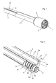
- a terminal unit for connection to one end of a flexible hose 2 having a predetermined external diameter, for fluid conveyance to a spray head.
- the other end of the hose is connected to a mixer unit for mixing hot and cold water, which can be installed on the wall under the kitchen sink, for example.
- the terminal unit 1 comprises a body 3 on the end of which is mounted a flexible external sheath 11 having a predetermined diameter, to enclose the flexible hose 2 and the body 3, purely for the sake of appearance and for connection to the spray head, not shown in the drawings because conventional.
- the body 3 comprises at least one housing seat 4 having an internal diameter substantially equal to the external diameter of the hose 2, to house the insertion of the terminal portion 2a of the hose 2.
- the terminal unit 1 comprises a sleeve 5 which can be inserted into the terminal portion 2a of the hose 2, intended to engage the terminal portion 2a of the hose 2 with predetermined pressure, so to press against body 3 from inside the tube 2.
- the sleeve 5 is equipped with external threading 5f having a predetermined pitch and profile, destined to be screwed to the terminal portion 2a of the hose 2, and with a tip portion 5b having a reduced section for easier insertion of the sleeve 5 into the terminal portion 2a of the flexible hose 2.
- the profile of sleeve 5 has a saw-tooth configuration, with the face side directed towards the tip portion.
- the body 3 comprises an annular ridge 3a formed in the seat 4 to provide an abutment for the head 3b against the terminal portion 2a of the hose 2 and against a flange 5a of the sleeve 5.
- the hose 2 can be inserted into the seat 4 through a first opening in the body 3, until the terminal portion 2a abuts against the annular ridge 3a, while the sleeve 5 is inserted into body 3 through a second opening in body 3, opposite the first opening, and screwed to the hose 2 until the flange 5a abuts against the annular ridge 3a.
- the position of the annular ridge 3a in body 3 determines the distance the flexible hose 2 and the sleeve 5 are inserted into the body 3 respectively.
- the sleeve 5 also comprises a portion 5c for hydraulic connection to the spray head, said portion projecting outside the annular ridge 3a when the sleeve is inserted into the flexible hose 2.
- the projecting portion 5c comprises a seat 5e for a gasket to seal the connection between the spray head and the sleeve 5.
- the terminal unit 1 permits the flexible hose 2 to be attached to the sleeve 5 without the need for strip fasteners or similar fixing elements that clamp the exterior of the hose 2 onto the sleeve 5, thus providing the possibility of using flexible hoses 2 with a diameter substantially equal to the diameter of the external flexible sheath 11 that encloses the flexible hose in question.
- the fluid flow rate from the flexible hose 2 to the spray head represents the maximum conveyable flow rate.
- the body 3 can also comprise two or more separate seats 4 for the insertion of terminal units 2a of two or more different flexible hoses 2, having a predetermined external diameter, conceived for differentiated fluid conveyance to the spray head.
- the separate seats 4 have an internal diameter substantially equal to the external diameter of the hoses 2.
- the two sleeves 5 can be inserted into the terminal portion 2a of the hoses 2, and are equipped with external threading 5f for screwing, with predetermined pressure, into the terminal portion 2a of the hoses 2, so to the hoses 2 against the body 3 from the interior.
- the body 3 between the two separate seats 4 has a predetermined thickness h, being thin enough so that the two seats are almost in contact with each other, the thickness h being equal to 4 tenths of a millimetre for example.
- the body 3 can also comprise two separate annular ridges 3a configured in the seats 4 to provide abutment between the head 3b and the terminal portion 2a of the hoses 2.
- the terminal unit 1 configured in this manner, is able to enclose the flexible hoses 2 inside an external flexible sheath 11 with a minimum interaxial distance between the hoses 2, thus providing the maximum differentiated fluid flow rate.
- the separate flexible hoses 2 are fixed by the respective sleeves 5 in pressure from the interior against the body 3.
- the terminal unit 1 permits the use of two separate flexible hoses 2 for differentiated fluid conveyance to two distribution chambers in a spray head, thus eliminating reduction in the fluid flow rate to the distribution chambers.
- the body 3 also comprises separate additional seats 6 to house the wiring 12 for electrical connection between the spray head and a control unit.
- the control unit is used to open and close the electrovalve for fluid cut-off in the respective flexible hoses 2.
- the terminal unit 1 comprises a support 7, having pass-through holes 7a in the projecting portion 5c of sleeve 5, and quick connect electrical connectors 7b to connect the control unit to the spray head.
- said electric connectors 7b comprise a plug portion 7c, equipped with electrical connections 7d for the electrical connection cables 12, for coupling to the related sockets in the spray heads.
- the support 7 is produced from an electrically insulated material and attached to body 3, by means of a system such a snap-on clamp system.
- the terminal unit 1 comprises a ring nut 8 having a substantially tubular shape to enclose said body, and conceived to be screwed to a respective portion of the spray head, and to enclose the sleeves 5, the electric connectors 7b, and the plug portions 7c as well as attaching the spray head to the terminal unit.
Landscapes
- Engineering & Computer Science (AREA)
- General Engineering & Computer Science (AREA)
- Mechanical Engineering (AREA)
- Joints That Cut Off Fluids, And Hose Joints (AREA)
Priority Applications (1)
| Application Number | Priority Date | Filing Date | Title |
|---|---|---|---|
| EP07008623A EP1985905A1 (de) | 2007-04-27 | 2007-04-27 | Anschlusseinheit für einen Schlauch zur Förderung einer Flüssigkeit in einen Sprühkopf |
Applications Claiming Priority (1)
| Application Number | Priority Date | Filing Date | Title |
|---|---|---|---|
| EP07008623A EP1985905A1 (de) | 2007-04-27 | 2007-04-27 | Anschlusseinheit für einen Schlauch zur Förderung einer Flüssigkeit in einen Sprühkopf |
Publications (1)
| Publication Number | Publication Date |
|---|---|
| EP1985905A1 true EP1985905A1 (de) | 2008-10-29 |
Family
ID=38480669
Family Applications (1)
| Application Number | Title | Priority Date | Filing Date |
|---|---|---|---|
| EP07008623A Withdrawn EP1985905A1 (de) | 2007-04-27 | 2007-04-27 | Anschlusseinheit für einen Schlauch zur Förderung einer Flüssigkeit in einen Sprühkopf |
Country Status (1)
| Country | Link |
|---|---|
| EP (1) | EP1985905A1 (de) |
Cited By (1)
| Publication number | Priority date | Publication date | Assignee | Title |
|---|---|---|---|---|
| US11598460B2 (en) | 2019-07-02 | 2023-03-07 | Hansgrohe Se | Multi-lumen hose and connector nipple |
Citations (8)
| Publication number | Priority date | Publication date | Assignee | Title |
|---|---|---|---|---|
| DE1244500B (de) * | 1962-04-19 | 1967-07-13 | Umberto Querci | Schlauchanschluss fuer Schlaeuche aus elastischem Material, insbesondere Kunststoff oder Gummi |
| EP0692664A1 (de) * | 1994-07-15 | 1996-01-17 | Hansen Developments Limited | Rohrverbindung |
| US20020016102A1 (en) * | 2000-07-26 | 2002-02-07 | Toshikazu Saba | Connector |
| US20020058436A1 (en) * | 2000-11-16 | 2002-05-16 | Toshikazu Saba | Connector |
| US6692037B1 (en) * | 2002-10-29 | 2004-02-17 | Global Industries Holdings Ltd. | Flat water hose and hose connectors for flat water hose |
| WO2005115264A1 (fr) * | 2004-05-28 | 2005-12-08 | Bien-Air Holding Sa | Tuyau et raccord polyvalent pour alimenter des instruments a usage dentaire ou chirurgical |
| EP1610049A2 (de) * | 2004-05-03 | 2005-12-28 | ContiTech Techno-Chemie GmbH | Schlauchverbindungssystem für einen beheizbaren Schlauch |
| EP1690601A1 (de) * | 2005-02-11 | 2006-08-16 | Sulzer Metco AG | Vorrichtung zum thermischen Spritzen |
-
2007
- 2007-04-27 EP EP07008623A patent/EP1985905A1/de not_active Withdrawn
Patent Citations (8)
| Publication number | Priority date | Publication date | Assignee | Title |
|---|---|---|---|---|
| DE1244500B (de) * | 1962-04-19 | 1967-07-13 | Umberto Querci | Schlauchanschluss fuer Schlaeuche aus elastischem Material, insbesondere Kunststoff oder Gummi |
| EP0692664A1 (de) * | 1994-07-15 | 1996-01-17 | Hansen Developments Limited | Rohrverbindung |
| US20020016102A1 (en) * | 2000-07-26 | 2002-02-07 | Toshikazu Saba | Connector |
| US20020058436A1 (en) * | 2000-11-16 | 2002-05-16 | Toshikazu Saba | Connector |
| US6692037B1 (en) * | 2002-10-29 | 2004-02-17 | Global Industries Holdings Ltd. | Flat water hose and hose connectors for flat water hose |
| EP1610049A2 (de) * | 2004-05-03 | 2005-12-28 | ContiTech Techno-Chemie GmbH | Schlauchverbindungssystem für einen beheizbaren Schlauch |
| WO2005115264A1 (fr) * | 2004-05-28 | 2005-12-08 | Bien-Air Holding Sa | Tuyau et raccord polyvalent pour alimenter des instruments a usage dentaire ou chirurgical |
| EP1690601A1 (de) * | 2005-02-11 | 2006-08-16 | Sulzer Metco AG | Vorrichtung zum thermischen Spritzen |
Cited By (1)
| Publication number | Priority date | Publication date | Assignee | Title |
|---|---|---|---|---|
| US11598460B2 (en) | 2019-07-02 | 2023-03-07 | Hansgrohe Se | Multi-lumen hose and connector nipple |
Similar Documents
| Publication | Publication Date | Title |
|---|---|---|
| US10519635B2 (en) | Exposed hose faucet | |
| US6757921B2 (en) | Pull-out faucet | |
| US9297151B2 (en) | Sanitary conduit, in particular for a shower device | |
| US4905766A (en) | Adapter for plastic pipe | |
| US20170151601A1 (en) | Showerhead and showerhead manufacturing method | |
| RU2376423C2 (ru) | Душевое устройство | |
| US7717133B2 (en) | Spout tip attachment | |
| US6829790B2 (en) | Add-on multi-head body spray shower | |
| WO2006120443A1 (en) | A mixer valve apparatus and a water delivery apparatus | |
| EP1985905A1 (de) | Anschlusseinheit für einen Schlauch zur Förderung einer Flüssigkeit in einen Sprühkopf | |
| US20100181519A1 (en) | Automatic switch valve | |
| US6467104B1 (en) | Faucet assembly having an attachable sprayer nozzle | |
| CA2361365C (en) | Fitting with fastening device | |
| CN212718595U (zh) | 一种管中管接头固定装置 | |
| WO2010061342A1 (en) | Shower Attachment | |
| JP6441758B2 (ja) | 湯水混合栓への給水および給湯ホース組付け機構 | |
| JP2008039125A (ja) | 配線又は配管材の貫通部形成部材及び装置 | |
| CN218480226U (zh) | 一种用于淋浴龙头的安装结构和淋浴龙头 | |
| KR200352796Y1 (ko) | 온수분배기 유량조절밸브의 연질관의 관접소켓 | |
| US9664323B2 (en) | Coupler | |
| CN111664279B (zh) | 具有集成的阀的可壁装的卫生管路连接装置 | |
| CN218738588U (zh) | 上进水淋浴柱 | |
| CN221034195U (zh) | 一种用于切换淋浴龙头花洒臂出水的淋浴龙头 | |
| CN213393780U (zh) | 一种连接结构和龙头 | |
| CN216618650U (zh) | 一种用于龙头的安装组件以及淋浴龙头 |
Legal Events
| Date | Code | Title | Description |
|---|---|---|---|
| PUAI | Public reference made under article 153(3) epc to a published international application that has entered the european phase |
Free format text: ORIGINAL CODE: 0009012 |
|
| AK | Designated contracting states |
Kind code of ref document: A1 Designated state(s): AT BE BG CH CY CZ DE DK EE ES FI FR GB GR HU IE IS IT LI LT LU LV MC MT NL PL PT RO SE SI SK TR |
|
| AX | Request for extension of the european patent |
Extension state: AL BA HR MK RS |
|
| AKX | Designation fees paid | ||
| REG | Reference to a national code |
Ref country code: DE Ref legal event code: 8566 |
|
| STAA | Information on the status of an ep patent application or granted ep patent |
Free format text: STATUS: THE APPLICATION IS DEEMED TO BE WITHDRAWN |
|
| 18D | Application deemed to be withdrawn |
Effective date: 20090430 |