EP1985842A1 - Starter - Google Patents
Starter Download PDFInfo
- Publication number
- EP1985842A1 EP1985842A1 EP08007114A EP08007114A EP1985842A1 EP 1985842 A1 EP1985842 A1 EP 1985842A1 EP 08007114 A EP08007114 A EP 08007114A EP 08007114 A EP08007114 A EP 08007114A EP 1985842 A1 EP1985842 A1 EP 1985842A1
- Authority
- EP
- European Patent Office
- Prior art keywords
- starter
- electromagnetic relay
- ventilation
- sealing cap
- motor
- Prior art date
- Legal status (The legal status is an assumption and is not a legal conclusion. Google has not performed a legal analysis and makes no representation as to the accuracy of the status listed.)
- Granted
Links
- 239000007858 starting material Substances 0.000 title claims abstract description 79
- 238000009423 ventilation Methods 0.000 claims abstract description 78
- 238000007789 sealing Methods 0.000 claims abstract description 47
- 238000002485 combustion reaction Methods 0.000 claims description 16
- 230000013011 mating Effects 0.000 claims description 2
- XLYOFNOQVPJJNP-UHFFFAOYSA-N water Substances O XLYOFNOQVPJJNP-UHFFFAOYSA-N 0.000 abstract description 33
- 230000009545 invasion Effects 0.000 abstract description 6
- 230000002093 peripheral effect Effects 0.000 abstract description 4
- 230000035939 shock Effects 0.000 description 8
- 238000004519 manufacturing process Methods 0.000 description 5
- 230000003247 decreasing effect Effects 0.000 description 4
- 230000005540 biological transmission Effects 0.000 description 3
- 230000007423 decrease Effects 0.000 description 3
- 230000004048 modification Effects 0.000 description 3
- 238000012986 modification Methods 0.000 description 3
- 241000221535 Pucciniales Species 0.000 description 1
- 238000004891 communication Methods 0.000 description 1
- 238000010586 diagram Methods 0.000 description 1
- 238000001035 drying Methods 0.000 description 1
- 230000000694 effects Effects 0.000 description 1
- 230000008014 freezing Effects 0.000 description 1
- 238000007710 freezing Methods 0.000 description 1
- WABPQHHGFIMREM-UHFFFAOYSA-N lead(0) Chemical compound [Pb] WABPQHHGFIMREM-UHFFFAOYSA-N 0.000 description 1
- 238000000034 method Methods 0.000 description 1
- 239000011347 resin Substances 0.000 description 1
- 229920005989 resin Polymers 0.000 description 1
Images


Classifications
-
- F—MECHANICAL ENGINEERING; LIGHTING; HEATING; WEAPONS; BLASTING
- F02—COMBUSTION ENGINES; HOT-GAS OR COMBUSTION-PRODUCT ENGINE PLANTS
- F02N—STARTING OF COMBUSTION ENGINES; STARTING AIDS FOR SUCH ENGINES, NOT OTHERWISE PROVIDED FOR
- F02N15/00—Other power-operated starting apparatus; Component parts, details, or accessories, not provided for in, or of interest apart from groups F02N5/00 - F02N13/00
-
- H—ELECTRICITY
- H01—ELECTRIC ELEMENTS
- H01H—ELECTRIC SWITCHES; RELAYS; SELECTORS; EMERGENCY PROTECTIVE DEVICES
- H01H50/00—Details of electromagnetic relays
- H01H50/02—Bases; Casings; Covers
- H01H50/023—Details concerning sealing, e.g. sealing casing with resin
-
- H—ELECTRICITY
- H01—ELECTRIC ELEMENTS
- H01H—ELECTRIC SWITCHES; RELAYS; SELECTORS; EMERGENCY PROTECTIVE DEVICES
- H01H50/00—Details of electromagnetic relays
- H01H50/12—Ventilating; Cooling; Heating
-
- H—ELECTRICITY
- H01—ELECTRIC ELEMENTS
- H01H—ELECTRIC SWITCHES; RELAYS; SELECTORS; EMERGENCY PROTECTIVE DEVICES
- H01H51/00—Electromagnetic relays
- H01H51/02—Non-polarised relays
- H01H51/04—Non-polarised relays with single armature; with single set of ganged armatures
- H01H51/06—Armature is movable between two limit positions of rest and is moved in one direction due to energisation of an electromagnet and after the electromagnet is de-energised is returned by energy stored during the movement in the first direction, e.g. by using a spring, by using a permanent magnet, by gravity
- H01H51/065—Relays having a pair of normally open contacts rigidly fixed to a magnetic core movable along the axis of a solenoid, e.g. relays for starting automobiles
-
- F—MECHANICAL ENGINEERING; LIGHTING; HEATING; WEAPONS; BLASTING
- F02—COMBUSTION ENGINES; HOT-GAS OR COMBUSTION-PRODUCT ENGINE PLANTS
- F02N—STARTING OF COMBUSTION ENGINES; STARTING AIDS FOR SUCH ENGINES, NOT OTHERWISE PROVIDED FOR
- F02N15/00—Other power-operated starting apparatus; Component parts, details, or accessories, not provided for in, or of interest apart from groups F02N5/00 - F02N13/00
- F02N15/02—Gearing between starting-engines and started engines; Engagement or disengagement thereof
- F02N15/04—Gearing between starting-engines and started engines; Engagement or disengagement thereof the gearing including disengaging toothed gears
- F02N15/06—Gearing between starting-engines and started engines; Engagement or disengagement thereof the gearing including disengaging toothed gears the toothed gears being moved by axial displacement
- F02N15/067—Gearing between starting-engines and started engines; Engagement or disengagement thereof the gearing including disengaging toothed gears the toothed gears being moved by axial displacement the starter comprising an electro-magnetically actuated lever
-
- F—MECHANICAL ENGINEERING; LIGHTING; HEATING; WEAPONS; BLASTING
- F02—COMBUSTION ENGINES; HOT-GAS OR COMBUSTION-PRODUCT ENGINE PLANTS
- F02N—STARTING OF COMBUSTION ENGINES; STARTING AIDS FOR SUCH ENGINES, NOT OTHERWISE PROVIDED FOR
- F02N2250/00—Problems related to engine starting or engine's starting apparatus
- F02N2250/08—Lubrication of starters; Sealing means for starters
Definitions
- the present invention relates to a starter of a constant meshing type in which the pinion gear is in constant meshing the ring gear of an internal combustion engine of a vehicle.
- Japanese patent laid open publication No. JP 2006-207573 has disclosed a conventional starter.
- a conventional starter is comprised of a motor that generates rotation power, an electromagnetic relay that performs ON/OFF control of a current to be supplied to the motor, a pinion gear that transmits a driving torque of the motor to the ring gear of an internal combustion engine.
- the pinion gear is in constant mesh with the ring gear.
- the starter mounted to a motor vehicle is often covered with water when the vehicle drives, it is better to use a closed-type electromagnetic relay which is closed when compared with an open-type electromagnetic relay. That is, when the open-type electromagnetic relay in the starter is covered with water, there is a high possibility that water enters into the inside of the open-type electromagnetic relay, and as a result, rusts and freezes the electrical contacts of the electromagnetic relay.
- closed-type electromagnetic relay is requested to have a strong sealing structure to withstand the inside pressure of the electromagnetic relay because a high inside pressure is generated in the closed-type electromagnetic relay when the plunger moves because when the plunger moves, great pressure is generated in the closed type electromagnetic relay.
- the closed-type electromagnet relay needs to perform the additional step (for example, a drying step) in order to completely remove water from the closed-type electromagnetic relay during its assembling step. Accordingly, because the starter with the closed-type electromagnetic relay needs to perform this complicated process, its manufacturing cost is increased when compared with that of the starter having the open-type electromagnetic relay.
- the starter with the closed-type electromagnetic relay there is a starter with an open passage in the housing to which the motor and the closed-type electromagnetic relay are fixed.
- the inside of the closed-type electromagnetic relay communicates with the outside atmosphere through an open passage, in order to drain water from the inside of the closed-type electromagnetic relay to the outside.
- the present invention provides a starter (1) that is comprised mainly of a motor (2), an output shaft (4), a pinion gear (5), an electromagnetic relay (6), and a housing (7).
- the motor (2) generates rotation power when receiving electric power.
- the output shaft (4) of the motor (2) rotates by the rotation power.
- the pinion gear (5) is placed on the output shaft (4) and is always engaged with a ring gear (13) of an internal combustion engine.
- the pinion gear (5) transmits a driving torque of the motor (2) in the starter (1) to the ring gear (13). Electrical contacts of a motor circuit of the motor (2) turns ON and OFF when a plunger (16) in the electromagnetic relay (6) is attracted and released (or returned to its original position).
- the motor (2) and the electromagnetic relay (6) are fixed to the housing (7).
- the housing (7) has a ventilation room (22) and an open passage (23). That is, the ventilation room (22) is formed in the housing (7) at a rear side of the plunger (16) in the electromagnet relay (6) assembled in the starter (1).
- the ventilation room (22) in communication with the inside of the electrical magnet relay (6) through a ventilation hole (17a, 17a-1, 17a-2, 17a-3) formed in a sealing cap (17, 17-1, 17-2, 17-3).
- the ventilation room (22) communicates with the outside atmosphere through the open passage (23).
- the housing-side part of the electromagnetic relay (6) is covered with the sealing cap (17, 17-1, 17-2, 17-3).
- the sealing cap (17, 17-1, 17-2, 17-3) has the ventilation hole (17a, 17a-1, 17a-2, 17a-3) to be placed in a ceiling-direction side of a vehicle, to which the starter (1) is mounted, when compared with the position of the ventilation room (22).
- the electromagnetic relay (6) communicates with the outside atmosphere through the ventilation hole (17a, 17a-1, 17a-2, 17a-3), the ventilation room (22), and the open passage (23).
- the electromagnet relay (6) does not need to have a strong sealing structure capable of withstanding the inside pressure of the electromagnetic relay (6) because the electromagnetic relay (6) communicates with the outside atmosphere through the ventilation hole (17a, 17a-1, 17a-2, 17a-3) formed in the sealing cap (17, 17-1, 17-2, 17-3), the ventilation room (22), and the open passage (23) formed in the housing (7). Furthermore, because the starter (1) with the electromagnetic relay (6) does not need to perform any water drain during the electromagnetic relay (6) assembling, it is possible to decrease the manufacturing cost of the starter (1) when compared with that for the starter with a conventional closed-type electromagnetic relay.
- the sealing cap (17, 17-1, 17-2, 17-3) is so placed that the ventilation hole (17a, 17a-1, 17a-2, 17a-3) is placed at an upper position when compared with the position of the ventilation room (22) when the starter (1) is mounted to a vehicle. Even if water enters the inside of the ventilation room (22) from the outside of the starter (1) through the open passage (23), the water can not reach the inside of the electromagnetic relay (6) through the ventilation hole (17a, 17a-1, 17a-2, 17a-3).
- This structure of the starter (1) according to the present invention can provide high-water proof function when the starter (1) is mounted to a vehicle which is often covered with water.
- the open passage (23) has open parts (23a, 23b) at one end and the other end thereof.
- the open part (23b) communicating with the ventilation room (22) would be placed at an upper side in the vehicle, to which the starter (1) is mounted, when compared with the position of the open part (23a) that communicates with the outside atmosphere.
- the open parts (23a, 23b) of the open passage (23) formed in the housing (7) have a difference in position. Even if water enters the inside of the open passage (23) through the open part (23b) communicating with the outside atmosphere, this structure can protect the open part (23a) at the ventilation room (22) side from water invasion. Still further, even if water in the open passage (23) enters the inside of the ventilation room (22), it is possible to easily drain the water through the open passage (23) because the open part (23a) is formed at the bottom part of the ventilation room (22).
- the sealing cap (17, 17-1, 17-2, 17-3) is positioned so that the ventilation hole (17a, 17a-1, 17a-2, 17a-3) is positioned at the upper part by positioning means (7c, 17b) formed in the housing (7) and the sealing cap (17, 17-1, 17-2, 17-3) when compared with the position of the ventilation room (22).
- the present invention can provide both a highly reliable and highly waterproof starter.
- the positioning means is composed of a convex part (17b) or a concave part formed in the sealing cap (17, 17-1, 17-2, 17-3) and a concave part (7c) or a convex part formed in the housing (7), and the sealing cap (17, 17-1, 17-2, 17-3) is positioned by mating the positioning means having the convex part (17b) and the concave part (7c).
- the present invention can provide the starter (1) with the electromagnetic relay (6) and the sealing cap (17, 17-1, 17-2, 17-3) with the positioning means with a simple structure using a combination of the concave part (7c) and the convex part (17b).
- the ventilation hole (17a-1, 17a-2, and 17a-3) is formed with a different shape. Because the ventilation hole (17a-1, 17a-2, and 17a-3) is formed in a curved shape (17a-1), a crank shape (17a-2), and a labyrinthine structure in which the ventilation hole (17a-3) has a crank shape (17a-3) with obstacle walls therein, it is possible to protect the electromagnetic relay (6) from direct water-invasion through the ventilation hole (17a-1, 17a-2, and 17a-3). This structure of the ventilation hole can enhance the water proof function of the electromagnetic relay (6) in the starter (1).
- FIG.1 is a side view showing the entire configuration of the starter 1 having the electromagnetic relay 6 of an improved water-proof function according to the first embodiment of the present invention.
- FIG. 2 is a front view of the housing 7 of the starter 1 shown in FIG. 1 , observed from the rear side of an internal combustion engine mounted to a vehicle.
- FIG. 3A is a cross section of the sealing cap 17 that covers and seals the electromagnetic relay 6 in the starter 1 according to the first embodiment shown in FIG. 1 .
- FIG. 3B is a plan view showing the sealing cap 17, observed from the plunger 16 side in the electromagnetic relay 6 of the starter 1 shown in FIG. 1 .
- the starter 1 is comprised mainly of the motor 2, the reduction device 3, the output shaft 4, the pinion gear 5, the shock absorbing device, the electromagnetic relay 6, and the housing 7.
- the motor 2 generates rotation power and outputs driving torque.
- the reduction device 3 is capable of reducing the rotation of the motor 2.
- the output shaft 4 transmits the driving torque of the motor 2 to the ring gear 13 of an internal combustion engine (not shown).
- the pinion gear 5 is supported by the output shaft 5.
- the shock absorbing device (will be explained later) is capable of absorbing shock applied to the driving mechanism of the starter 1 through the pinion gear 5.
- the electromagnetic relay 6 turns the electrical contacts placed in the motor circuit ON and OFF for the motor 2.
- the motor 2 and the electromagnetic relay 6 are fixed to the housing 7.
- the motor 2 is a well-known DC electric motor.
- the motor 2 receives electric power of the battery (not shown) mounted to the vehicle.
- the armature (not shown) built in the motor 2 generates rotation power.
- the motor 2 is tightly fixed to the housing 7 by through bolts 8.
- the reduction device 3 is an epicycle reduction gear composed of planet gears capable of decreasing the rotation speed transmitted from the motor 2 through the armature shaft 9. The decreased rotation speed obtained through the planet gear 10 is transmitted to the output shaft 4.
- the output shaft 4 and the armature shaft 9 are placed on the same axis.
- the end part of the output shaft 4, which is the opposite side of the motor 2 is rotatebly supported to the nose section 7a of the housing 7 through the shaft bearing 11.
- the other end part of the output shaft 5, which is the same side of the motor 2, is connected to the armature shaft 9 through the reduction device 3.
- the pinion gear 5 is rotatably engaged with the outer periphery of the output shaft 4 through the bearing 12. In addition, the pinion gear 5 is always engaged with the ring gear 13 of the internal combustion engine (not shown). The motor torque that is amplified by the reduction device 3 when the internal combustion engine (not shown) starts and the amplified one is transmitted to the ring gear 13.
- the shock absorbing device is composed mainly of the shock absorbing member 14 made of rubber or another member placed between the output shaft 4 and the pinion gear 5.
- the shock absorbing device is capable of absorbing shock applied to the driving mechanism of the starter 1.
- the shock absorbing member 14 is elastically compressed when an excess power is applied to the pinion gear 5 through the ring gear 13.
- the electromagnetic relay 6 is comprised of the built-in electromagnetic coil 15 and the built-in plunger 16.
- the electromagnetic coil 15 forms an electromagnet. This electromagnet operates on receiving electric power of the battery (not shown) mounted to a vehicle.
- the plunger 16 moves on the inner periphery of the electromagnetic coil 15 in its axial direction (toward the right and left directions).
- the electromagnet is formed in the electromagnetic coil 15.
- the plunger 16 is forcedly attracted, and the main electrical contact connected to the plunger 16 is electrically closed, namely, turns ON.
- the electromagnetic relay 6 is placed close to the outside in the radial direction of the motor 2 and fixed to the housing 7 by pairs of bolts and nuts (not shown).
- the inner-peripheral hollow section of the electromagnetic coil 15 is sealed with the sealing cap 17.
- the inner-peripheral hollow section of the electromagnetic coil 15 opens toward the housing side in the axial direction (toward the left side in FIG. 1 ).
- This sealing cap 17 covers the end part of the plunger 16 which projects toward the housing 7 side from the end surface in the axial direction of the electromagnetic-coil case.
- This electromagnetic-coil case accommodates the electromagnetic coil 15.
- the outer peripheral edge part of the sealing cap 17 is supported between the end surface in the axial direction of the electromagnetic-coil case and the housing 7 when the electromagnetic relay 6 is fixed to the housing 7.
- This sealing cap 17 has one ventilation hole 17a through which the electromagnetic relay 6 is ventilated (see FIG. 3A and FIG. 3B ).
- the plate member 18 (see FIG. 1 ) is placed in the inside of the sealing cap 17.
- the plunger 16 is returned to its original position by the return spring, and is finally contacted to the plate member 18.
- the main electrical contact is composed mainly of the pair of fixed contacts and a movable contact.
- the pair of fixed contacts (not shown) is connected to the motor circuit through the pair of outer terminals 19 and 20.
- the movable contact and the plunger 16 move together.
- the movable contact electrically connects the pair of fixed contacts. That is, the main electrical contact enters the closed state when the movable contact is pushed to the pair of fixed contacts and the fixed contacts are electrically connected through the movable contact.
- the main electrical contact enters the open state when the movable contact is separated from the pair of fixed contacts and the fixed contacts are electrically disconnected.
- the pair of outer terminals is composed of the B terminal 19 and the M terminal 20.
- the B terminal 19 is electrically connected to the battery plus (+) terminal through a battery cable.
- the M terminal 20 is electrically connected to the motor lead wire 21 in the motor 2. Those B terminal 19 and the M terminal 20 are fixed to the resin cover 6a of the electromagnetic relay 6.
- the housing 7 has a nose part 7a.
- the nose part 7a is inserted into the internal combustion engine side through an open part formed in the starter attachment wall (for example, the transmission case) placed in the internal combustion engine side.
- the pinion gear 5 is accommodated in the inside of the nose part 7a.
- the open part 7b is formed at the ring gear side in the radial direction of the nose part 7a.
- the pinion gear 5 is engaged with the ring gear 13. That is, the inside of the housing 7 communicates with the outside atmosphere through the open part 7b.
- the housing 7 has the cylindrical hole, the ventilation room 22, and the open passage 23.
- the cylindrical hole in the housing 7 has a larger inner radius than the outer radial of the plunger 16.
- the ventilation room 22 is formed from the bottom part of the cylindrical hole toward the depth direction of the housing 7. Through the open passage 23, the ventilation room 22 communicates with the outside atmosphere through the open passage 23.
- the sealing cap 17 is placed in the cylindrical hole in the housing 7. Although the sealing cap 17 separates the electromagnetic relay 6 from the ventilation room 22, the inside of the electromagnetic relay 6 communicated with the ventilation room 22 through the ventilation hole 17a formed in the sealing cap 17.
- the ventilation hole 17a communicates with the communicating room 22a.
- the communicating room 22a is formed in a part of the ventilation room 22 so that the ventilation room 22 is extended toward the outside of the radial direction thereof.
- the communicating room 22a is formed in the upper part (, or toward the ceiling direction of the vehicle) of the ventilation room 22.
- the sealing cap 17 is also positioned toward the circumferential direction of the sealing cap 17 by the positioning means formed in the housing 7 and the sealing cap 17.
- this positioning means is composed mainly of the concave part 7c (see FIG. 2 ) formed in the housing 7 and the convex part 17b (see FIG. 3 ) formed at the outer peripheral part of the sealing cap 17.
- the concave part 7c and the convex part 17b it is possible that the convex part is formed in the housing 7 and the concave part is formed at the outer peripheral part of the sealing cap 17.
- the concave part 7c and the convex part 17b are engaged together and the sealing cap 17 is positioned at the housing 7 toward the circumferential direction.
- the open part 23a is placed at a higher position rather than the position of the open part 23b, where the open part 23a communicates with the bottom part of the ventilation room 22, and the open part 23b communicates with the outside atmosphere.
- the armature of the motor 2 starts to rotate when the electromagnetic relay 6 receives electrical power supplied from the battery (not shown), the main electrical contact is closed (namely, turns ON), and the electrical power is thereby supplied to the motor 2.
- the reduction device 3 decreases the rotation speed of the armature of the motor 2, and transmits the rotation power of the armature to the output shaft 4.
- the rotation power of the motor 2 is then transmitted from the pinion gear 5 to the ring gear 13.
- the internal combustion engine (not shown) that is cranked to the ring gear 13 starts to rotate by the rotation power.
- the rotation speed of the armature in the motor 2 is gradually decreased when the main electrical contact is open (namely, turns OFF), and the electric power supply from the battery to the motor 2 in the starter 1 is halted. Finally, the motor 2 in the starter 1 stops.
- the starter 1 according to the present invention does not need to have any sealing mechanism capable of resisting the high inside pressure of the electromagnetic relay 6 caused when the plunger 16 moves. Further, because the inside of the electromagnetic relay 6 always communicates with the outside atmosphere, the manufacturing work for the starter 1 according to the present invention does not need to drain water during the electromagnetic relay assembling. As a result, it is possible to decrease the manufacturing cost of the starter 1 with the electromagnetic relay 6 according to the present invention when compared with that of the starter having the conventional closed-type electromagnet relay.
- the open part 23a is placed at a higher position of the ceiling of a vehicle, to which the starter 1 is mounted, when compared with the open part 23b communicating with the outside atmosphere, it is possible to protect the open part 23a of the open passage 23 at the ventilation room 22 side from water invasion even if water enters in the inside of the open passage 23 through the open part 23b at the outer atmosphere side.
- the ceiling cap 17 is so placed in the housing 7 that the ventilation hole 17a formed in the sealing cap 17 points toward the ceiling direction of the starter 1 shown in FIG. 1 when compared with the position of the ventilation room 22.
- the ventilation hole 17a is placed at the upper part of the ventilation room 22, it is possible to vent water accumulated in the ventilation room 22 to the outside of the starter 1 through the open passage 23.
- This structure protects the electromagnetic relay 6 from water invasion by the position of the ventilation hole 17a even if water reaches the ventilation room 22.
- This structure of the starter 1 according to the present invention can maintain a higher water-proof function even if the starter 1 is mounted to a vehicle and the vehicle is always covered with water when wind and rain hit the vehicle.
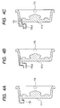
- FIG. 4A to FIG. 4C are cross sections showing three different modifications of the ventilation holes 17a-1, 17a-2, 17a-3 formed in the sealing caps 17-1, 17-2, 17-3, respectively.
- Each sealing cap covers the electromagnetic relay 6 of the starter 1 according to the second embodiment of the present invention.
- the ventilation hole 17a-1 of a curved shape is formed in the ceiling cap 17-1.
- the ventilation hole 17a-2 of a crank shape without any obstacle wall is formed in the ceiling cap 17-2.
- the ventilation hole 17a-3 of a crank shape having obstacle walls therein as a labyrinthine structure is formed in the ceiling cap 17-3.
- the ceiling caps 17-1, 17-2, and 17-3 used in the starter according to the second embodiment can protect the electromagnetic relay 6 from direct invasion of water.
- This structure of the ceiling caps 17-1, 17-2, and 17-3 can increase the water proof function.
Landscapes
- Physics & Mathematics (AREA)
- Electromagnetism (AREA)
- Engineering & Computer Science (AREA)
- Chemical & Material Sciences (AREA)
- Combustion & Propulsion (AREA)
- Mechanical Engineering (AREA)
- General Engineering & Computer Science (AREA)
- Connection Of Motors, Electrical Generators, Mechanical Devices, And The Like (AREA)
- Motor Or Generator Frames (AREA)
Abstract
Description
- The present invention relates to a starter of a constant meshing type in which the pinion gear is in constant meshing the ring gear of an internal combustion engine of a vehicle.
- Japanese patent laid open publication No.
JP 2006-207573 JP 2006-207573 - Because the starter mounted to a motor vehicle is often covered with water when the vehicle drives, it is better to use a closed-type electromagnetic relay which is closed when compared with an open-type electromagnetic relay. That is, when the open-type electromagnetic relay in the starter is covered with water, there is a high possibility that water enters into the inside of the open-type electromagnetic relay, and as a result, rusts and freezes the electrical contacts of the electromagnetic relay.
- On the other hand, there is almost no possibility of rusting or freezing the electrical contacts of the closed-type electromagnetic relay in the starter because of having a low possibility of water invasion.
- However, such a closed-type electromagnetic relay is requested to have a strong sealing structure to withstand the inside pressure of the electromagnetic relay because a high inside pressure is generated in the closed-type electromagnetic relay when the plunger moves because when the plunger moves, great pressure is generated in the closed type electromagnetic relay. Furthermore, the closed-type electromagnet relay needs to perform the additional step (for example, a drying step) in order to completely remove water from the closed-type electromagnetic relay during its assembling step. Accordingly, because the starter with the closed-type electromagnetic relay needs to perform this complicated process, its manufacturing cost is increased when compared with that of the starter having the open-type electromagnetic relay.
- In order to decreasing the manufacturing cost of the starter with the closed-type electromagnetic relay, there is a starter with an open passage in the housing to which the motor and the closed-type electromagnetic relay are fixed. In the starter, the inside of the closed-type electromagnetic relay communicates with the outside atmosphere through an open passage, in order to drain water from the inside of the closed-type electromagnetic relay to the outside.
- However, if the vehicle is covered with a lot of water and the water is accumulated in the transmission case of the vehicle when the ring gear operates, the water would enter the inside of the closed-type electromagnetic relay through the open passage formed in the housing.
- It is an object of the present invention to provide a starter with an electromagnetic relay with an improved water-proof function.
- To achieve the above purposes, the present invention provides a starter (1) that is comprised mainly of a motor (2), an output shaft (4), a pinion gear (5), an electromagnetic relay (6), and a housing (7). The motor (2) generates rotation power when receiving electric power. The output shaft (4) of the motor (2) rotates by the rotation power. The pinion gear (5) is placed on the output shaft (4) and is always engaged with a ring gear (13) of an internal combustion engine. The pinion gear (5) transmits a driving torque of the motor (2) in the starter (1) to the ring gear (13). Electrical contacts of a motor circuit of the motor (2) turns ON and OFF when a plunger (16) in the electromagnetic relay (6) is attracted and released (or returned to its original position). The motor (2) and the electromagnetic relay (6) are fixed to the housing (7). The housing (7) has a ventilation room (22) and an open passage (23). That is, the ventilation room (22) is formed in the housing (7) at a rear side of the plunger (16) in the electromagnet relay (6) assembled in the starter (1). The ventilation room (22) in communication with the inside of the electrical magnet relay (6) through a ventilation hole (17a, 17a-1, 17a-2, 17a-3) formed in a sealing cap (17, 17-1, 17-2, 17-3). The ventilation room (22) communicates with the outside atmosphere through the open passage (23). The housing-side part of the electromagnetic relay (6) is covered with the sealing cap (17, 17-1, 17-2, 17-3). The sealing cap (17, 17-1, 17-2, 17-3) has the ventilation hole (17a, 17a-1, 17a-2, 17a-3) to be placed in a ceiling-direction side of a vehicle, to which the starter (1) is mounted, when compared with the position of the ventilation room (22).
- The electromagnetic relay (6) communicates with the outside atmosphere through the ventilation hole (17a, 17a-1, 17a-2, 17a-3), the ventilation room (22), and the open passage (23).
- The electromagnet relay (6) does not need to have a strong sealing structure capable of withstanding the inside pressure of the electromagnetic relay (6) because the electromagnetic relay (6) communicates with the outside atmosphere through the ventilation hole (17a, 17a-1, 17a-2, 17a-3) formed in the sealing cap (17, 17-1, 17-2, 17-3), the ventilation room (22), and the open passage (23) formed in the housing (7). Furthermore, because the starter (1) with the electromagnetic relay (6) does not need to perform any water drain during the electromagnetic relay (6) assembling, it is possible to decrease the manufacturing cost of the starter (1) when compared with that for the starter with a conventional closed-type electromagnetic relay.
- Still further, the sealing cap (17, 17-1, 17-2, 17-3) is so placed that the ventilation hole (17a, 17a-1, 17a-2, 17a-3) is placed at an upper position when compared with the position of the ventilation room (22) when the starter (1) is mounted to a vehicle. Even if water enters the inside of the ventilation room (22) from the outside of the starter (1) through the open passage (23), the water can not reach the inside of the electromagnetic relay (6) through the ventilation hole (17a, 17a-1, 17a-2, 17a-3). This structure of the starter (1) according to the present invention can provide high-water proof function when the starter (1) is mounted to a vehicle which is often covered with water.
- In the starter (1) according to another aspect of the present invention, the open passage (23) has open parts (23a, 23b) at one end and the other end thereof. The open part (23b) communicating with the ventilation room (22) would be placed at an upper side in the vehicle, to which the starter (1) is mounted, when compared with the position of the open part (23a) that communicates with the outside atmosphere.
- The open parts (23a, 23b) of the open passage (23) formed in the housing (7) have a difference in position. Even if water enters the inside of the open passage (23) through the open part (23b) communicating with the outside atmosphere, this structure can protect the open part (23a) at the ventilation room (22) side from water invasion. Still further, even if water in the open passage (23) enters the inside of the ventilation room (22), it is possible to easily drain the water through the open passage (23) because the open part (23a) is formed at the bottom part of the ventilation room (22).
- In the starter (1) according to another aspect of the present invention, the sealing cap (17, 17-1, 17-2, 17-3) is positioned so that the ventilation hole (17a, 17a-1, 17a-2, 17a-3) is positioned at the upper part by positioning means (7c, 17b) formed in the housing (7) and the sealing cap (17, 17-1, 17-2, 17-3) when compared with the position of the ventilation room (22).
- Because the ventilation hole (17a, 17a-1, 17a-2, 17a-3) can be easily and certainly positioned at the upper part when compared with the position of the ventilation room (22) in the sealing direction of a vehicle to which the starter (1) is mounted, the present invention can provide both a highly reliable and highly waterproof starter.
- In the starter (1) according to another aspect of the present invention, the positioning means is composed of a convex part (17b) or a concave part formed in the sealing cap (17, 17-1, 17-2, 17-3) and a concave part (7c) or a convex part formed in the housing (7), and the sealing cap (17, 17-1, 17-2, 17-3) is positioned by mating the positioning means having the convex part (17b) and the concave part (7c). The present invention can provide the starter (1) with the electromagnetic relay (6) and the sealing cap (17, 17-1, 17-2, 17-3) with the positioning means with a simple structure using a combination of the concave part (7c) and the convex part (17b).
- In the starter (1) according to another aspect of the present invention, the ventilation hole (17a-1, 17a-2, and 17a-3) is formed with a different shape. Because the ventilation hole (17a-1, 17a-2, and 17a-3) is formed in a curved shape (17a-1), a crank shape (17a-2), and a labyrinthine structure in which the ventilation hole (17a-3) has a crank shape (17a-3) with obstacle walls therein, it is possible to protect the electromagnetic relay (6) from direct water-invasion through the ventilation hole (17a-1, 17a-2, and 17a-3). This structure of the ventilation hole can enhance the water proof function of the electromagnetic relay (6) in the starter (1).
- A preferred, non-limiting embodiment of the present invention will be described by way of example with reference to the accompanying drawings, in which:
-
FIG.1 is a side view showing the entire configuration of the starter having the electromagnetic relay of an improved water-proof function according to the first embodiment of the present invention; -
FIG. 2 is a front view of the housing of the starter shown inFIG. 1 , observed from the rear side of an internal combustion engine mounted to a vehicle; -
FIG. 3A is a cross section of the sealing cap that covers and seals the electromagnetic relay of the starter according to the first embodiment shown inFIG. 1 ; -
FIG. 3B is a plan view showing the sealing cap observed from the plunger side in the electromagnetic relay of the starter shown inFIG. 1 ; and -
FIG. 4A to FIG. 4C , each is a cross section showing a modification of the ventilation hole formed in the sealing cap for the electromagnetic relay of the starter according to the second embodiment of the present invention. - Hereinafter, various embodiments of the present invention will be described with reference to the accompanying drawings. In the following description of the various embodiments, like reference characters or numerals designate like or equivalent component parts throughout the several diagrams.
- A description will be given of the starter according to the first embodiment of the present invention with reference to
FIG. 1 ,FIG. 2 ,FIG. 3A, and FIG. 3B . -
FIG.1 is a side view showing the entire configuration of thestarter 1 having theelectromagnetic relay 6 of an improved water-proof function according to the first embodiment of the present invention.FIG. 2 is a front view of thehousing 7 of thestarter 1 shown inFIG. 1 , observed from the rear side of an internal combustion engine mounted to a vehicle.FIG. 3A is a cross section of the sealingcap 17 that covers and seals theelectromagnetic relay 6 in thestarter 1 according to the first embodiment shown inFIG. 1 .FIG. 3B is a plan view showing the sealingcap 17, observed from theplunger 16 side in theelectromagnetic relay 6 of thestarter 1 shown inFIG. 1 . - As shown in
FIG. 1 , thestarter 1 is comprised mainly of themotor 2, thereduction device 3, the output shaft 4, the pinion gear 5, the shock absorbing device, theelectromagnetic relay 6, and thehousing 7. - The
motor 2 generates rotation power and outputs driving torque. Thereduction device 3 is capable of reducing the rotation of themotor 2. The output shaft 4 transmits the driving torque of themotor 2 to thering gear 13 of an internal combustion engine (not shown). The pinion gear 5 is supported by the output shaft 5. The shock absorbing device (will be explained later) is capable of absorbing shock applied to the driving mechanism of thestarter 1 through the pinion gear 5. Theelectromagnetic relay 6 turns the electrical contacts placed in the motor circuit ON and OFF for themotor 2. Themotor 2 and theelectromagnetic relay 6 are fixed to thehousing 7. - The
motor 2 is a well-known DC electric motor. When the main electrical contact is closed by theelectromagnetic relay 6, themotor 2 receives electric power of the battery (not shown) mounted to the vehicle. The armature (not shown) built in themotor 2 generates rotation power. Themotor 2 is tightly fixed to thehousing 7 by throughbolts 8. - The
reduction device 3 is an epicycle reduction gear composed of planet gears capable of decreasing the rotation speed transmitted from themotor 2 through thearmature shaft 9. The decreased rotation speed obtained through theplanet gear 10 is transmitted to the output shaft 4. - The output shaft 4 and the
armature shaft 9 are placed on the same axis. The end part of the output shaft 4, which is the opposite side of themotor 2, is rotatebly supported to thenose section 7a of thehousing 7 through theshaft bearing 11. - The other end part of the output shaft 5, which is the same side of the
motor 2, is connected to thearmature shaft 9 through thereduction device 3. - The pinion gear 5 is rotatably engaged with the outer periphery of the output shaft 4 through the
bearing 12. In addition, the pinion gear 5 is always engaged with thering gear 13 of the internal combustion engine (not shown). The motor torque that is amplified by thereduction device 3 when the internal combustion engine (not shown) starts and the amplified one is transmitted to thering gear 13. - The shock absorbing device is composed mainly of the
shock absorbing member 14 made of rubber or another member placed between the output shaft 4 and the pinion gear 5. - The shock absorbing device is capable of absorbing shock applied to the driving mechanism of the
starter 1. For example, theshock absorbing member 14 is elastically compressed when an excess power is applied to the pinion gear 5 through thering gear 13. - The
electromagnetic relay 6 is comprised of the built-inelectromagnetic coil 15 and the built-inplunger 16. Theelectromagnetic coil 15 forms an electromagnet. This electromagnet operates on receiving electric power of the battery (not shown) mounted to a vehicle. Theplunger 16 moves on the inner periphery of theelectromagnetic coil 15 in its axial direction (toward the right and left directions). When the electric power is supplied to theelectromagnetic coil 15, the electromagnet is formed in theelectromagnetic coil 15. Thereby, theplunger 16 is forcedly attracted, and the main electrical contact connected to theplunger 16 is electrically closed, namely, turns ON. - When the electric power supply from the battery to the
electromagnetic coil 15 is halted, and the attraction force thereby disappears, theplunger 16 is forcedly returned to its original position by the force of a return spring (not shown), and the main electrical contact is thereby open, namely, turns OFF. - As shown in
FIG. 1 , theelectromagnetic relay 6 is placed close to the outside in the radial direction of themotor 2 and fixed to thehousing 7 by pairs of bolts and nuts (not shown). - In the
electromagnetic relay 6, the inner-peripheral hollow section of theelectromagnetic coil 15 is sealed with the sealingcap 17. The inner-peripheral hollow section of theelectromagnetic coil 15 opens toward the housing side in the axial direction (toward the left side inFIG. 1 ). - This sealing
cap 17 covers the end part of theplunger 16 which projects toward thehousing 7 side from the end surface in the axial direction of the electromagnetic-coil case. This electromagnetic-coil case accommodates theelectromagnetic coil 15. The outer peripheral edge part of the sealingcap 17 is supported between the end surface in the axial direction of the electromagnetic-coil case and thehousing 7 when theelectromagnetic relay 6 is fixed to thehousing 7. - This sealing
cap 17 has oneventilation hole 17a through which theelectromagnetic relay 6 is ventilated (seeFIG. 3A and FIG. 3B ). - The plate member 18 (see
FIG. 1 ) is placed in the inside of the sealingcap 17. Theplunger 16 is returned to its original position by the return spring, and is finally contacted to theplate member 18. - The main electrical contact is composed mainly of the pair of fixed contacts and a movable contact. The pair of fixed contacts (not shown) is connected to the motor circuit through the pair of
outer terminals plunger 16 move together. The movable contact electrically connects the pair of fixed contacts. That is, the main electrical contact enters the closed state when the movable contact is pushed to the pair of fixed contacts and the fixed contacts are electrically connected through the movable contact. The main electrical contact enters the open state when the movable contact is separated from the pair of fixed contacts and the fixed contacts are electrically disconnected. - The pair of outer terminals is composed of the
B terminal 19 and theM terminal 20. TheB terminal 19 is electrically connected to the battery plus (+) terminal through a battery cable. TheM terminal 20 is electrically connected to themotor lead wire 21 in themotor 2. ThoseB terminal 19 and theM terminal 20 are fixed to theresin cover 6a of theelectromagnetic relay 6. - The
housing 7 has anose part 7a. Thenose part 7a is inserted into the internal combustion engine side through an open part formed in the starter attachment wall (for example, the transmission case) placed in the internal combustion engine side. - The pinion gear 5 is accommodated in the inside of the
nose part 7a. As shown inFIG. 2 , theopen part 7b is formed at the ring gear side in the radial direction of thenose part 7a. Through theopen part 7b, the pinion gear 5 is engaged with thering gear 13. That is, the inside of thehousing 7 communicates with the outside atmosphere through theopen part 7b. - As shown in
FIG. 1 , thehousing 7 has the cylindrical hole, theventilation room 22, and theopen passage 23. The cylindrical hole in thehousing 7 has a larger inner radius than the outer radial of theplunger 16. Theventilation room 22 is formed from the bottom part of the cylindrical hole toward the depth direction of thehousing 7. Through theopen passage 23, theventilation room 22 communicates with the outside atmosphere through theopen passage 23. - The sealing
cap 17 is placed in the cylindrical hole in thehousing 7. Although the sealingcap 17 separates theelectromagnetic relay 6 from theventilation room 22, the inside of theelectromagnetic relay 6 communicated with theventilation room 22 through theventilation hole 17a formed in the sealingcap 17. - Specifically, as shown in
FIG. 1 , theventilation hole 17a communicates with the communicatingroom 22a. The communicatingroom 22a is formed in a part of theventilation room 22 so that theventilation room 22 is extended toward the outside of the radial direction thereof. The communicatingroom 22a is formed in the upper part (, or toward the ceiling direction of the vehicle) of theventilation room 22. - The sealing
cap 17 is also positioned toward the circumferential direction of the sealingcap 17 by the positioning means formed in thehousing 7 and the sealingcap 17. - For example, this positioning means is composed mainly of the
concave part 7c (seeFIG. 2 ) formed in thehousing 7 and theconvex part 17b (seeFIG. 3 ) formed at the outer peripheral part of the sealingcap 17. Instead of theconcave part 7c and theconvex part 17b, it is possible that the convex part is formed in thehousing 7 and the concave part is formed at the outer peripheral part of the sealingcap 17. - The
concave part 7c and theconvex part 17b are engaged together and the sealingcap 17 is positioned at thehousing 7 toward the circumferential direction. - As shown in
FIG. 2 , theopen part 23a is placed at a higher position rather than the position of theopen part 23b, where theopen part 23a communicates with the bottom part of theventilation room 22, and theopen part 23b communicates with the outside atmosphere. - Next, a description will now be given of the operation of the
starter 1 according to the first embodiment of the present invention. - The armature of the
motor 2 starts to rotate when theelectromagnetic relay 6 receives electrical power supplied from the battery (not shown), the main electrical contact is closed (namely, turns ON), and the electrical power is thereby supplied to themotor 2. - The
reduction device 3 decreases the rotation speed of the armature of themotor 2, and transmits the rotation power of the armature to the output shaft 4. The rotation power of themotor 2 is then transmitted from the pinion gear 5 to thering gear 13. The internal combustion engine (not shown) that is cranked to thering gear 13 starts to rotate by the rotation power. - When the rotation speed of the internal combustion engine exceeds the rotation speed of the
starter 1, a one-way clutch (not shown) built in thering gear 13 starts to race, and thering gear 13 is separated from the crank shaft of the internal combustion engine. This can avoid the transmission of the rotation speed of the internal combustion engine to the pinion gear 5, and protect the armature of themotor 2 in thestarter 1 from over-running. - After the internal combustion engine starts, the rotation speed of the armature in the
motor 2 is gradually decreased when the main electrical contact is open (namely, turns OFF), and the electric power supply from the battery to themotor 2 in thestarter 1 is halted. Finally, themotor 2 in thestarter 1 stops. - Because the inside of the
electromagnetic relay 6 communicates with the outside atmosphere through theventilation hole 17a formed in the sealingcap 17, theventilation room 22 and theopen passage 23 formed in thehousing 7, thestarter 1 according to the present invention does not need to have any sealing mechanism capable of resisting the high inside pressure of theelectromagnetic relay 6 caused when theplunger 16 moves. Further, because the inside of theelectromagnetic relay 6 always communicates with the outside atmosphere, the manufacturing work for thestarter 1 according to the present invention does not need to drain water during the electromagnetic relay assembling. As a result, it is possible to decrease the manufacturing cost of thestarter 1 with theelectromagnetic relay 6 according to the present invention when compared with that of the starter having the conventional closed-type electromagnet relay. - In addition, because the
open part 23a is placed at a higher position of the ceiling of a vehicle, to which thestarter 1 is mounted, when compared with theopen part 23b communicating with the outside atmosphere, it is possible to protect theopen part 23a of theopen passage 23 at theventilation room 22 side from water invasion even if water enters in the inside of theopen passage 23 through theopen part 23b at the outer atmosphere side. - Still further, even if water reaches the
ventilation room 22 through theopen part 23a of theopen passage 23, it is possible to avoid water accumulated in theventilation room 22 and to easily drain the water to the outside of thestarter 1 through theopen passage 23 because theopen part 23a of theopen passage 23 is placed at the bottom side of theventilation room 22. - Furthermore, the
ceiling cap 17 is so placed in thehousing 7 that theventilation hole 17a formed in the sealingcap 17 points toward the ceiling direction of thestarter 1 shown inFIG. 1 when compared with the position of theventilation room 22. In other words, as shown inFIG. 1 , because theventilation hole 17a is placed at the upper part of theventilation room 22, it is possible to vent water accumulated in theventilation room 22 to the outside of thestarter 1 through theopen passage 23. This structure protects theelectromagnetic relay 6 from water invasion by the position of theventilation hole 17a even if water reaches theventilation room 22. This structure of thestarter 1 according to the present invention can maintain a higher water-proof function even if thestarter 1 is mounted to a vehicle and the vehicle is always covered with water when wind and rain hit the vehicle. - A description will be given of the starter according to the second embodiment of the present invention with reference to
FIG. 4A, FIG. 4B, and FIG. 4C . -
FIG. 4A to FIG. 4C are cross sections showing three different modifications of theventilation holes 17a-1, 17a-2, 17a-3 formed in the sealing caps 17-1, 17-2, 17-3, respectively. Each sealing cap covers theelectromagnetic relay 6 of thestarter 1 according to the second embodiment of the present invention. - As shown in
FIG. 4A , theventilation hole 17a-1 of a curved shape is formed in the ceiling cap 17-1. - As shown in
FIG. 4B , theventilation hole 17a-2 of a crank shape without any obstacle wall is formed in the ceiling cap 17-2. - As shown in
FIG. 4C , theventilation hole 17a-3 of a crank shape having obstacle walls therein as a labyrinthine structure is formed in the ceiling cap 17-3. - When compared with the configuration of the
ceiling cap 17 shown inFIG. 3A and FIG. 3B that is used in thestarter 1 according to the first embodiment, the ceiling caps 17-1, 17-2, and 17-3 used in the starter according to the second embodiment can protect theelectromagnetic relay 6 from direct invasion of water. This structure of the ceiling caps 17-1, 17-2, and 17-3 can increase the water proof function. - While specific embodiments of the present invention have been described in detail, it will be appreciated by those skilled in the art that various modifications and alternatives to those details could be developed in light of the overall teachings of the disclosure. Accordingly, the particular arrangements disclosed are meant to be illustrative only and not limited to the scope of the present invention which is to be given the full breadth of the following claims and all equivalent thereof.
Claims (7)
- A starter (1) comprising:a motor (2) that generates rotation power;an output shaft (4) of the motor (2) that rotates by the rotation power;a pinion gear (5) that is placed on the output shaft (4) and is always engaged with a ring gear (13) of an internal combustion engine, and transmits a driving torque of the motor (2) to the ring gear (13);an electromagnetic relay (6) having a plunger (16) by which electrical contacts of a motor circuit of the motor (2) turn ON and OFF;a housing (7), to which the motor (2) and the electromagnetic relay (6) are fixed, having a ventilation room (22) and an open passage (23), where the ventilation room (22) is formed in the housing (7) at a rear side of the plunger (16), and the ventilation room (22) is joined to an inside of the electrical magnet relay (6) through a ventilation hole (17a, 17a-1, 17a-2, 17a-3) formed in a sealing cap (17, 17-1, 17-2, 17-3), and the ventilation room (22) is communicated to an outside atmosphere through the open passage (23); andthe sealing cap (17, 17-1, 17-2, 17-3), with which a housing-side part of the electromagnetic relay (6) is covered, having the ventilation hole (17a, 17a-1, 17a-2, 17a-3), to be placed in a ceiling-direction side of a vehicle to which the starter (1) would be mounted, when compared with the position of the ventilation room (22).
- The starter (1) as claimed in claim 1, wherein the open passage (23) has open parts (23a, 23b) at one end and the other end thereof, the open part (23b) communicating with the ventilation room (22) would be placed at an upper side in the vehicle, to which the starter (1) is mounted, when compared with the position of the open part (23a) that communicates with the outside atmosphere.
- The starter as claimed in claim 1 or 2, wherein the sealing cap (17, 17-1, 17-2, 17-3) is positioned so that the ventilation hole (17a, 17a-1, 17a-2, 17a-3) is positioned at the upper part by positioning means (7c, 17b) formed in the housing (7) and the sealing cap (17, 17-1, 17-2, 17-3) when compared with the position of the ventilation room (22).
- The starter as claimed in claim 3, wherein the positioning means is composed of a convex part (17b) or a concave part formed in the sealing cap and a concave part (7c) or a convex part formed in the housing (7), and the sealing cap (17, 17-1, 17-2, 17-3) is positioned by mating the positioning means having the convex part (17b) and the concave part (7c).
- The starter as claimed in any one of claims 1 to 4, wherein the ventilation hole (17a-1) of a curved shape is formed in the ceiling cap (17-1).
- The starter as claimed in any one of claims 1 to 4, wherein the ventilation hole (17a-2) of a crank shape is formed in the ceiling cap (17-2).
- The starter as claimed in any one of claims 1 to 4, wherein the ventilation hole (17a-3) of a labyrinthine structure of a crank shape having obstacle walls therein is formed in the ceiling cap (17-3).
Applications Claiming Priority (1)
| Application Number | Priority Date | Filing Date | Title |
|---|---|---|---|
| JP2007118553A JP4240133B2 (en) | 2007-04-27 | 2007-04-27 | Starter |
Publications (2)
| Publication Number | Publication Date |
|---|---|
| EP1985842A1 true EP1985842A1 (en) | 2008-10-29 |
| EP1985842B1 EP1985842B1 (en) | 2013-10-09 |
Family
ID=39441976
Family Applications (1)
| Application Number | Title | Priority Date | Filing Date |
|---|---|---|---|
| EP20080007114 Ceased EP1985842B1 (en) | 2007-04-27 | 2008-04-10 | Starter |
Country Status (2)
| Country | Link |
|---|---|
| EP (1) | EP1985842B1 (en) |
| JP (1) | JP4240133B2 (en) |
Cited By (2)
| Publication number | Priority date | Publication date | Assignee | Title |
|---|---|---|---|---|
| CN102213175A (en) * | 2010-04-09 | 2011-10-12 | 罗伯特·博世有限公司 | Sealing device and starting device for pre-engagement actuator |
| EP3016121A1 (en) * | 2014-11-03 | 2016-05-04 | Robert Bosch Gmbh | Starter and solenoid switch thereof |
Families Citing this family (1)
| Publication number | Priority date | Publication date | Assignee | Title |
|---|---|---|---|---|
| JP2017040231A (en) * | 2015-08-21 | 2017-02-23 | 株式会社デンソー | magnetic switch |
Citations (8)
| Publication number | Priority date | Publication date | Assignee | Title |
|---|---|---|---|---|
| JPS61291770A (en) * | 1985-06-19 | 1986-12-22 | Nippon Denso Co Ltd | Starter |
| EP0398627A1 (en) * | 1989-05-17 | 1990-11-22 | Mitsubishi Denki Kabushiki Kaisha | Water cover arrangement for a solenoid apparatus |
| US5053633A (en) * | 1989-05-12 | 1991-10-01 | Mitsubishi Denki Kabushiki Kaisha | Moisture drain bush for an engine starter motor |
| US5181002A (en) * | 1990-12-28 | 1993-01-19 | Mitsubishi Denki K.K. | Electromagnetic switch for starter |
| EP1213514A2 (en) * | 2000-12-05 | 2002-06-12 | Trelleborg Ab | Protective covers |
| JP2006207573A (en) | 2004-12-27 | 2006-08-10 | Denso Corp | Starter |
| FR2887933A1 (en) * | 2005-06-17 | 2007-01-05 | Denso Corp | ENGINE STARTING SYSTEM COMPRISING TWO DIFFERENT TYPE STARTERS |
| FR2891320A1 (en) * | 2005-09-13 | 2007-03-30 | Denso Corp | Starter for internal combustion engine of motor vehicle, has unidirectional clutch disposed on armature shaft and comprising sealing element for preventing loss of lubricant used in clutch towards motor |
-
2007
- 2007-04-27 JP JP2007118553A patent/JP4240133B2/en not_active Expired - Fee Related
-
2008
- 2008-04-10 EP EP20080007114 patent/EP1985842B1/en not_active Ceased
Patent Citations (8)
| Publication number | Priority date | Publication date | Assignee | Title |
|---|---|---|---|---|
| JPS61291770A (en) * | 1985-06-19 | 1986-12-22 | Nippon Denso Co Ltd | Starter |
| US5053633A (en) * | 1989-05-12 | 1991-10-01 | Mitsubishi Denki Kabushiki Kaisha | Moisture drain bush for an engine starter motor |
| EP0398627A1 (en) * | 1989-05-17 | 1990-11-22 | Mitsubishi Denki Kabushiki Kaisha | Water cover arrangement for a solenoid apparatus |
| US5181002A (en) * | 1990-12-28 | 1993-01-19 | Mitsubishi Denki K.K. | Electromagnetic switch for starter |
| EP1213514A2 (en) * | 2000-12-05 | 2002-06-12 | Trelleborg Ab | Protective covers |
| JP2006207573A (en) | 2004-12-27 | 2006-08-10 | Denso Corp | Starter |
| FR2887933A1 (en) * | 2005-06-17 | 2007-01-05 | Denso Corp | ENGINE STARTING SYSTEM COMPRISING TWO DIFFERENT TYPE STARTERS |
| FR2891320A1 (en) * | 2005-09-13 | 2007-03-30 | Denso Corp | Starter for internal combustion engine of motor vehicle, has unidirectional clutch disposed on armature shaft and comprising sealing element for preventing loss of lubricant used in clutch towards motor |
Cited By (3)
| Publication number | Priority date | Publication date | Assignee | Title |
|---|---|---|---|---|
| CN102213175A (en) * | 2010-04-09 | 2011-10-12 | 罗伯特·博世有限公司 | Sealing device and starting device for pre-engagement actuator |
| CN102213175B (en) * | 2010-04-09 | 2015-06-03 | 罗伯特·博世有限公司 | Sealing device and starting device for pre-engagement actuator |
| EP3016121A1 (en) * | 2014-11-03 | 2016-05-04 | Robert Bosch Gmbh | Starter and solenoid switch thereof |
Also Published As
| Publication number | Publication date |
|---|---|
| JP4240133B2 (en) | 2009-03-18 |
| EP1985842B1 (en) | 2013-10-09 |
| JP2008274830A (en) | 2008-11-13 |
Similar Documents
| Publication | Publication Date | Title |
|---|---|---|
| US8754556B2 (en) | Apparatus for starting engine mounted on-vehicle | |
| CN103985601B (en) | Electromagnetic switch | |
| US7834497B2 (en) | Starter | |
| WO2011086967A1 (en) | Electromagnetic relay | |
| JP4089587B2 (en) | Starter | |
| CN103036364B (en) | Starter including noise reduction filter | |
| KR20080010289A (en) | Starter with minimized electromagnetic switch | |
| EP1985842B1 (en) | Starter | |
| EP0895334B1 (en) | Electric rotating machine having radially outwardly extending bulge on yoke | |
| JP4772098B2 (en) | Electromagnetic switch for starter | |
| US5494010A (en) | Magnet switch and a starter using same | |
| JP5910336B2 (en) | Electromagnetic solenoid device | |
| CA2233087A1 (en) | A starter for an internal combustion engine | |
| JPH05101731A (en) | Connecting terminal | |
| JP4111053B2 (en) | Starter | |
| JPH10238441A (en) | Starter | |
| JP4508119B2 (en) | Starter | |
| KR100600558B1 (en) | Magnetic switch with surge protection diode | |
| RU2830501C1 (en) | Device for emergency shutdown of vehicle power supply in flooding conditions | |
| JPH08270533A (en) | Engine starting device | |
| JP2009174435A (en) | Starter | |
| JP3658864B2 (en) | Starter | |
| JP3767018B2 (en) | Starter | |
| JPH09324727A (en) | Starter | |
| KR19990020726A (en) | Electronic switch of starting motor |
Legal Events
| Date | Code | Title | Description |
|---|---|---|---|
| PUAI | Public reference made under article 153(3) epc to a published international application that has entered the european phase |
Free format text: ORIGINAL CODE: 0009012 |
|
| AK | Designated contracting states |
Kind code of ref document: A1 Designated state(s): AT BE BG CH CY CZ DE DK EE ES FI FR GB GR HR HU IE IS IT LI LT LU LV MC MT NL NO PL PT RO SE SI SK TR |
|
| AX | Request for extension of the european patent |
Extension state: AL BA MK RS |
|
| 17P | Request for examination filed |
Effective date: 20080930 |
|
| AKX | Designation fees paid |
Designated state(s): DE FR |
|
| GRAP | Despatch of communication of intention to grant a patent |
Free format text: ORIGINAL CODE: EPIDOSNIGR1 |
|
| GRAJ | Information related to disapproval of communication of intention to grant by the applicant or resumption of examination proceedings by the epo deleted |
Free format text: ORIGINAL CODE: EPIDOSDIGR1 |
|
| GRAP | Despatch of communication of intention to grant a patent |
Free format text: ORIGINAL CODE: EPIDOSNIGR1 |
|
| INTG | Intention to grant announced |
Effective date: 20130404 |
|
| INTG | Intention to grant announced |
Effective date: 20130418 |
|
| GRAS | Grant fee paid |
Free format text: ORIGINAL CODE: EPIDOSNIGR3 |
|
| GRAA | (expected) grant |
Free format text: ORIGINAL CODE: 0009210 |
|
| AK | Designated contracting states |
Kind code of ref document: B1 Designated state(s): DE FR |
|
| REG | Reference to a national code |
Ref country code: DE Ref legal event code: R096 Ref document number: 602008027964 Country of ref document: DE Effective date: 20131205 |
|
| REG | Reference to a national code |
Ref country code: DE Ref legal event code: R097 Ref document number: 602008027964 Country of ref document: DE |
|
| PLBE | No opposition filed within time limit |
Free format text: ORIGINAL CODE: 0009261 |
|
| STAA | Information on the status of an ep patent application or granted ep patent |
Free format text: STATUS: NO OPPOSITION FILED WITHIN TIME LIMIT |
|
| 26N | No opposition filed |
Effective date: 20140710 |
|
| REG | Reference to a national code |
Ref country code: DE Ref legal event code: R097 Ref document number: 602008027964 Country of ref document: DE Effective date: 20140710 |
|
| REG | Reference to a national code |
Ref country code: FR Ref legal event code: PLFP Year of fee payment: 9 |
|
| REG | Reference to a national code |
Ref country code: FR Ref legal event code: PLFP Year of fee payment: 10 |
|
| REG | Reference to a national code |
Ref country code: FR Ref legal event code: PLFP Year of fee payment: 11 |
|
| PGFP | Annual fee paid to national office [announced via postgrant information from national office to epo] |
Ref country code: DE Payment date: 20200420 Year of fee payment: 13 Ref country code: FR Payment date: 20200420 Year of fee payment: 13 |
|
| REG | Reference to a national code |
Ref country code: DE Ref legal event code: R119 Ref document number: 602008027964 Country of ref document: DE |
|
| PG25 | Lapsed in a contracting state [announced via postgrant information from national office to epo] |
Ref country code: FR Free format text: LAPSE BECAUSE OF NON-PAYMENT OF DUE FEES Effective date: 20210430 Ref country code: DE Free format text: LAPSE BECAUSE OF NON-PAYMENT OF DUE FEES Effective date: 20211103 |