WO2011086967A1 - Electromagnetic relay - Google Patents
Electromagnetic relay Download PDFInfo
- Publication number
- WO2011086967A1 WO2011086967A1 PCT/JP2011/050111 JP2011050111W WO2011086967A1 WO 2011086967 A1 WO2011086967 A1 WO 2011086967A1 JP 2011050111 W JP2011050111 W JP 2011050111W WO 2011086967 A1 WO2011086967 A1 WO 2011086967A1
- Authority
- WO
- WIPO (PCT)
- Prior art keywords
- relay
- control circuit
- contact
- motor
- coil
- Prior art date
Links
Images


Classifications
-
- H—ELECTRICITY
- H01—ELECTRIC ELEMENTS
- H01H—ELECTRIC SWITCHES; RELAYS; SELECTORS; EMERGENCY PROTECTIVE DEVICES
- H01H50/00—Details of electromagnetic relays
- H01H50/02—Bases; Casings; Covers
- H01H50/021—Bases; Casings; Covers structurally combining a relay and an electronic component, e.g. varistor, RC circuit
-
- H—ELECTRICITY
- H01—ELECTRIC ELEMENTS
- H01H—ELECTRIC SWITCHES; RELAYS; SELECTORS; EMERGENCY PROTECTIVE DEVICES
- H01H50/00—Details of electromagnetic relays
- H01H50/02—Bases; Casings; Covers
- H01H50/04—Mounting complete relay or separate parts of relay on a base or inside a case
-
- F—MECHANICAL ENGINEERING; LIGHTING; HEATING; WEAPONS; BLASTING
- F02—COMBUSTION ENGINES; HOT-GAS OR COMBUSTION-PRODUCT ENGINE PLANTS
- F02N—STARTING OF COMBUSTION ENGINES; STARTING AIDS FOR SUCH ENGINES, NOT OTHERWISE PROVIDED FOR
- F02N11/00—Starting of engines by means of electric motors
- F02N11/08—Circuits or control means specially adapted for starting of engines
- F02N11/087—Details of the switching means in starting circuits, e.g. relays or electronic switches
-
- F—MECHANICAL ENGINEERING; LIGHTING; HEATING; WEAPONS; BLASTING
- F02—COMBUSTION ENGINES; HOT-GAS OR COMBUSTION-PRODUCT ENGINE PLANTS
- F02N—STARTING OF COMBUSTION ENGINES; STARTING AIDS FOR SUCH ENGINES, NOT OTHERWISE PROVIDED FOR
- F02N15/00—Other power-operated starting apparatus; Component parts, details, or accessories, not provided for in, or of interest apart from groups F02N5/00 - F02N13/00
- F02N15/02—Gearing between starting-engines and started engines; Engagement or disengagement thereof
- F02N15/04—Gearing between starting-engines and started engines; Engagement or disengagement thereof the gearing including disengaging toothed gears
- F02N15/06—Gearing between starting-engines and started engines; Engagement or disengagement thereof the gearing including disengaging toothed gears the toothed gears being moved by axial displacement
- F02N15/067—Gearing between starting-engines and started engines; Engagement or disengagement thereof the gearing including disengaging toothed gears the toothed gears being moved by axial displacement the starter comprising an electro-magnetically actuated lever
-
- H—ELECTRICITY
- H01—ELECTRIC ELEMENTS
- H01H—ELECTRIC SWITCHES; RELAYS; SELECTORS; EMERGENCY PROTECTIVE DEVICES
- H01H50/00—Details of electromagnetic relays
- H01H50/44—Magnetic coils or windings
-
- H—ELECTRICITY
- H01—ELECTRIC ELEMENTS
- H01H—ELECTRIC SWITCHES; RELAYS; SELECTORS; EMERGENCY PROTECTIVE DEVICES
- H01H51/00—Electromagnetic relays
- H01H51/02—Non-polarised relays
- H01H51/04—Non-polarised relays with single armature; with single set of ganged armatures
- H01H51/06—Armature is movable between two limit positions of rest and is moved in one direction due to energisation of an electromagnet and after the electromagnet is de-energised is returned by energy stored during the movement in the first direction, e.g. by using a spring, by using a permanent magnet, by gravity
- H01H51/065—Relays having a pair of normally open contacts rigidly fixed to a magnetic core movable along the axis of a solenoid, e.g. relays for starting automobiles
-
- F—MECHANICAL ENGINEERING; LIGHTING; HEATING; WEAPONS; BLASTING
- F02—COMBUSTION ENGINES; HOT-GAS OR COMBUSTION-PRODUCT ENGINE PLANTS
- F02D—CONTROLLING COMBUSTION ENGINES
- F02D2400/00—Control systems adapted for specific engine types; Special features of engine control systems not otherwise provided for; Power supply, connectors or cabling for engine control systems
- F02D2400/18—Packaging of the electronic circuit in a casing
-
- F—MECHANICAL ENGINEERING; LIGHTING; HEATING; WEAPONS; BLASTING
- F02—COMBUSTION ENGINES; HOT-GAS OR COMBUSTION-PRODUCT ENGINE PLANTS
- F02N—STARTING OF COMBUSTION ENGINES; STARTING AIDS FOR SUCH ENGINES, NOT OTHERWISE PROVIDED FOR
- F02N11/00—Starting of engines by means of electric motors
- F02N11/10—Safety devices
-
- F—MECHANICAL ENGINEERING; LIGHTING; HEATING; WEAPONS; BLASTING
- F02—COMBUSTION ENGINES; HOT-GAS OR COMBUSTION-PRODUCT ENGINE PLANTS
- F02N—STARTING OF COMBUSTION ENGINES; STARTING AIDS FOR SUCH ENGINES, NOT OTHERWISE PROVIDED FOR
- F02N11/00—Starting of engines by means of electric motors
- F02N11/08—Circuits or control means specially adapted for starting of engines
- F02N2011/0881—Components of the circuit not provided for by previous groups
-
- F—MECHANICAL ENGINEERING; LIGHTING; HEATING; WEAPONS; BLASTING
- F02—COMBUSTION ENGINES; HOT-GAS OR COMBUSTION-PRODUCT ENGINE PLANTS
- F02N—STARTING OF COMBUSTION ENGINES; STARTING AIDS FOR SUCH ENGINES, NOT OTHERWISE PROVIDED FOR
- F02N2250/00—Problems related to engine starting or engine's starting apparatus
- F02N2250/02—Battery voltage drop at start, e.g. drops causing ECU reset
-
- F—MECHANICAL ENGINEERING; LIGHTING; HEATING; WEAPONS; BLASTING
- F02—COMBUSTION ENGINES; HOT-GAS OR COMBUSTION-PRODUCT ENGINE PLANTS
- F02N—STARTING OF COMBUSTION ENGINES; STARTING AIDS FOR SUCH ENGINES, NOT OTHERWISE PROVIDED FOR
- F02N2250/00—Problems related to engine starting or engine's starting apparatus
- F02N2250/08—Lubrication of starters; Sealing means for starters
Definitions
- the present invention relates to an electromagnetic relay provided in a motor circuit of a starter, and in particular, includes a resistor for suppressing a motor starting current when starting an engine, bypassing the resistor after starting the motor,
- the present invention relates to an electromagnetic relay that energizes a motor with all voltages.
- a starter for starting an engine is equipped with an electromagnetic switch that pushes a pinion toward the ring gear and opens and closes a main contact provided in a motor circuit (a circuit for flowing current from a battery to a motor). Yes.
- an inrush current flows from the battery to the motor. Occurrence of this inrush current may cause a phenomenon called so-called “instantaneous interruption” in which the terminal voltage of the battery is greatly reduced, and electric devices such as meters and audio are instantaneously stopped.
- the present applicant has proposed a technique capable of preventing the occurrence of “instantaneous interruption” by suppressing the inrush current that flows when the motor starts.
- the invention according to Patent Document 1 includes a motor energizing relay 102 (electromagnetic relay) that can open and close a motor circuit, in addition to the electromagnetic switch 101 mounted on the starter 100.
- the motor energization relay (relay) 102 includes a resistor 105 connected to the motor circuit via two terminal bolts 103 and 104, and an upstream end and a downstream end of the resistor 105. And a relay contact 106 constituted by a set of fixed contacts.
- the relay 102 has a function of opening and closing the relay contact 106 by a movable contact 108 that can move according to the excitation state of the relay coil 107.
- the excitation state of the relay coil 107 is controlled by a drive signal output from the control circuit 109 (see FIG. 12). For example, when the drive signal of the control circuit 109 is on, the relay coil 107 is excited to close (turn on) the relay contact 106, and when the drive signal of the control circuit 109 is off, the relay coil 107 is de-energized. Then, the relay contact 106 is opened (turned off).
- the drive signal of the control circuit 109 is off, the relay coil 107 is not excited, and the relay contact 106 is open.
- the electromagnetic switch 101 closes the main contact 111, the current suppressed by the resistor 105 flows to the motor 110, so the motor 110 rotates at a low speed.
- the drive signal is switched from OFF to ON.
- the relay coil 107 is excited and the relay contact 106 is closed, whereby both ends of the resistor 105 are short-circuited via the relay contact 106. Due to the short circuit between both ends of the resistor 105, the entire voltage of the battery 114 is applied to the motor 110, and a higher current flows through the motor 110 than at the time of startup, thereby increasing the rotational speed of the motor 110.
- control circuit 109 when the control circuit 109 is installed in the vehicle interior or the exterior of the vehicle separately from the motor energization relay 102, it is necessary to prepare a dedicated housing for incorporating the control circuit 109. . Further, by connecting the control circuit 109 and the battery 114 via a power supply line and connecting the control circuit 109 and the motor energization relay 102 via a signal line, a drive signal is sent to the motor energization relay 102. Must be sendable. In this case, wiring for driving the power supply line, the signal line, and the motor energizing relay 102 is necessary, and this increases the number of connection parts such as connectors.
- control circuit 109 when the control circuit 109 is installed outside the passenger compartment, a waterproof structure for the housing containing the control circuit 109 is required to protect the control circuit 109 from rainwater and the like.
- the present invention has been made based on the above circumstances, and an object of one aspect thereof is to maintain high reliability of an electromagnetic relay using a resistor energization control circuit for preventing “instantaneous interruption”. There is to do.
- an object of another aspect of the present invention is to maintain high environmental resistance of an electromagnetic relay using a control circuit for resistance energization control for preventing “instantaneous interruption”.
- an electromagnetic relay for starting a starter motor, and a resistor for suppressing a starting current flowing from a battery to the motor when the motor is started, A relay contact for bypassing the resistor to flow the starting current, a relay coil that is excited by energization to form an electromagnet, and controls the excitation state of the relay coil when the motor is started to open and close the relay contact And a control circuit for controlling energization of the motor from the battery via the resistor, and the electromagnetic relay incorporates the control circuit.
- the control circuit is built in the electromagnetic relay, so that a housing dedicated to the control circuit is not required. For this reason, it is possible to reduce the number of connection points such as connectors for connecting the wirings, and it is possible to simplify the wiring around the electromagnetic relay, leading to an improvement in reliability.
- control circuit in the electromagnetic relay, it is not necessary to secure a space for installing the control circuit separately from the electromagnetic relay, thereby improving the mountability.
- a case having a bottom portion at one end side along the axial direction of the relay coil and an opening portion opened at the other end side along the axial direction, and accommodated inside the case.
- first and second partition members which are disposed on one end side and the other end side in the axial direction of the relay coil, respectively forming a part of the magnetic circuit, and the opening of the case is closed
- the relay contact, the movable contact is in contact with the first and second fixed contacts, and the two fixed contacts are electrically connected through the movable contact.
- the movable contact is opened when the movable contact is separated from the first and second fixed contacts
- control circuit and the relay coil can be facilitated by accommodating the control circuit inside the casing of the electromagnetic relay.
- control circuit and the relay coil of the electromagnetic relay are connected by electric wiring, and the electric wiring is connected to the outside. Exposed. For this reason, it is necessary to pay attention to the handling of the electrical wiring, and there is a risk of disconnection due to external vibration (for example, engine vibration).
- the electrical connection between the control circuit and the relay coil can be completed inside the casing of the electromagnetic relay, the electrical wiring connecting the control circuit and the relay coil is electromagnetic There is no need to route outside the relay, and there is no fear of disconnection due to vibration.
- waterproofness can be ensured by the casing of the electromagnetic relay, so that reliability and environmental resistance can be improved.
- the invention according to claim 3 is the electromagnetic relay according to claim 1 or 2, characterized in that the control circuit is constituted by an IC.
- IC integrated circuit
- control circuit can be miniaturized by using the IC, the IC can be easily accommodated in a limited space of the electromagnetic relay, and the electromagnetic relay incorporating the control circuit can be miniaturized. .
- the IC has a package for protecting the circuit element, and the package is one of the first partition member and the second partition member. It is characterized by being attached in close contact with either one.
- One of the first partition member and the second partition member is a magnetic body that forms a part of the magnetic circuit, and is formed of a metal member such as iron.
- the IC package is attached in close contact with either the first partition member or the second partition member, which is a metal member, to generate heat (Joule heat) due to circuit loss in the first Heat can be radiated to one of the partition member and the second partition member, so that the life of the circuit can be improved and the energization time can be extended.
- the invention according to claim 5 is the electromagnetic relay according to claim 4, wherein the relay coil includes a coil body and a resin bobbin that is a winding frame around which the coil body is wound,
- the IC is molded into a resin member formed integrally with the resin bobbin together with one of the first partition member and the second partition member in close contact with the package.
- the IC can be securely fixed by molding the IC on the resin member, and contact wear powder or the like does not accumulate between the IC terminals, so that it is possible to prevent the insulation from being lowered between the IC terminals. .
- the electromagnetic relay in the electromagnetic relay according to the fifth aspect of the present invention, includes an external terminal that is taken out of the cover, and a signal transmission terminal that transmits a signal input through the external terminal to the IC.
- the signal transmission terminal is secondarily formed inside the cylindrical body portion of the bobbin that supports the inner diameter of the relay coil, and the IC is integrated with the bobbin together with the first partition member, with the package in close contact with the first partition member. It is molded on a resin member formed in the above, and is connected to an external terminal through a signal transmission terminal.
- the coated lead wire connected to the IC is relayed after being wound around the bobbin. It is necessary to connect to the external terminal through the outside in the radial direction of the coil. In this case, since it is necessary to secure a space for passing the coated lead wire or the like on the radially outer side of the relay coil, the dimension in the radial direction is inevitably increased, and the electromagnetic relay is increased in size.
- the IC and the external terminal can be connected via the signal transmission terminal by passing the signal transmission terminal inside the cylindrical body portion of the bobbin.
- the electromagnetic relay since it is not necessary to secure a space outside the radial direction of the relay coil, the electromagnetic relay can be reduced in size.
- the external terminal and the signal transmission terminal may be separate parts, but both may be provided integrally.
- the invention according to claim 7 is the electromagnetic relay according to any one of claims 1 to 6, wherein the control circuit closes the relay contact without energizing the motor via the resistor when starting the motor.
- the start-up current suppression prohibition function is, for example, in an idle stop vehicle that automatically controls stop and restart of the engine, when the idle stop is prohibited on the system, in other words, when the engine is cold and it is difficult to start.
- the function of suppressing the current is prohibited. That is, instead of energizing the motor via the resistor when the motor is started, the relay contact is closed and the motor is energized by the full voltage of the battery. As a result, engine startability is improved even during cold weather when the engine is difficult to start.
- the temperature protection function prevents the occurrence of a circuit failure by shutting off the power supplied to the control circuit by itself when an abnormal temperature exceeding a preset allowable temperature is detected.
- the overcurrent protection function prevents the occurrence of a circuit failure by shutting off the power supplied to the control circuit by itself when an overcurrent exceeding a preset allowable current flows.
- the resistor energization time adjustment function has a function of adjusting the energization time to the resistor when the motor is energized via the resistor when the motor is started. For example, the startability of the engine can be improved and the battery voltage drop caused by the starter current can be suppressed by extending the energization time to the resistor (the time when the relay contact is open) when the starter is at a high temperature. In this way, it is possible to supply the starter current with a good balance.
- the movable contact contacts the first and second fixed contacts and the normally closed contact closes.
- the control circuit has at least a temperature protection function and is arranged in the contact chamber.
- control circuit of the invention Since the control circuit of the invention according to claim 8 is arranged in the contact chamber like the resistor, it receives radiant heat radiated from the resistor when the resistor is energized. Thereby, for example, when the resistor generates heat due to abnormal continuous energization of the resistor and the control circuit senses an abnormal temperature, the power supply to the control circuit is cut off by the function of the temperature protection function.
- the control circuit is arranged at an appropriate distance from the resistor so as not to fail before the temperature protection function is activated due to the heat generated by the resistor. In other words, it is arranged in a region where the temperature protection function functions effectively when the resistor generates heat.
- the resistor is not blown, so it is not necessary to replace the resistor, it can be used as it is, and the control circuit is not broken. Function.
- the invention according to claim 9 is the electromagnetic relay according to any one of claims 1 to 8, wherein the control circuit is electrically connected to a power supply line for supplying power from the battery to the relay coil, and moreover than the relay coil. It is electrically arranged on the upstream side.
- the electromagnetic relay of the present invention for connecting the bottomed case to the ground can be connected to the power input terminal, the relay coil signal input terminal, and the relay coil ground terminal without significantly changing the signal path of the control circuit. Therefore, the control circuit of the present invention can be easily applied to similar electromagnetic relays.
- control circuit is electrically connected to a power supply line that supplies power from the battery to the relay coil, and moreover than the relay coil. It is electrically arranged on the downstream side.
- the current flowing out of the relay coil can flow from the ground terminal of the control circuit to the ground side. That is, since the ground terminal of the control circuit and the ground terminal of the relay coil can be shared, the number of terminals can be reduced.
- a power supply line that supplies power to the control circuit, a power supply line that supplies power to the relay coil, and the control circuit are activated.
- the power supply to the control circuit and the relay coil is received from the energization line, and a trigger signal is taken in.
- the power supply dedicated line can be omitted, so that the number of terminals of the electromagnetic relay can be reduced and simplified.
- the electromagnetic relay of the present invention functions only by supplying a branch signal from the energizing line of the starter electromagnetic switch without significantly changing the conventional vehicle wiring.
- the invention according to claim 12 is the electromagnetic relay according to claim 11, wherein the control circuit includes a MOSFET for controlling the excitation state of the relay coil, and a surge absorbing element that absorbs a surge generated when the starter relay is opened. It is characterized by having.
- the surge absorbing element incorporated in the control circuit can absorb the surge generated when the relay coil is turned off (when the starter relay is opened). Further, the surge that enters the control circuit from the exciting coil of the starter electromagnetic switch through the energization line can be absorbed together by the effect of the parasitic diode of the MOSFET built in the control circuit. Thereby, since the arc generated from the contact of the starter relay caused by the surge generated in the exciting coil of the starter electromagnetic switch when the energization is stopped can be reduced, the contact life of the starter relay can be improved.
- the first embodiment is an example in which the electromagnetic relay of the present invention is provided in a motor circuit of a starter 1 (see FIG. 3) for starting an internal combustion engine (engine) for a vehicle, for example.
- the electromagnetic relay according to the form is called a motor energizing relay 2.
- the starter 1 is movable in the axial direction on a motor 3 that generates a rotational force, an output shaft 4 that is driven by the motor 3 to rotate, and an outer periphery of the output shaft 4. And a provided pinion moving body (described later).
- the starter 1 has a function of pushing out the pinion moving body in the direction opposite to the motor (right direction in the drawing), an electromagnetic switch 5 that opens and closes a main contact (described later) provided in a motor circuit described later, a shift lever 15,
- the motor energization relay 2 and the like described above including the resistor 7 for suppressing the starting current flowing from the battery 6 to the motor 3 are provided.
- a reduction device for example, a planetary gear reduction device for amplifying torque by reducing the rotation of the motor 3 may be provided between the motor 3 and the output shaft 4.
- FIG. 3 shows a control system for driving and controlling the starter 1.
- the control system includes a battery 6, a start switch 42, and the motor energization relay 2 described above (hereinafter simply referred to as a relay 2).
- a relay 2 the motor energization relay 2 described above (hereinafter simply referred to as a relay 2).
- the motor 3 is composed of a permanent magnet or an electromagnet, and includes a field (not shown) that generates a magnetic field, an armature 3b having a commutator 3a, a brush 8 disposed on the outer periphery of the commutator 3a, and the like. It is a known commutator motor. That is, the motor 3 rotates the output shaft 4 based on the relative action of the magnetic field generated from the armature 3b by energization via the brush 8 and the commutator 3a and the magnetic field generated by the field. ing.
- the pinion moving body includes a clutch 9 and a pinion 10.
- the clutch 9 is composed of an outer that is helically spline fitted to the outer periphery of the output shaft 4, an inner that is provided integrally with the pinion 10, and a roller that intermittently transmits the rotational force between the outer and the inner.
- the clutch 9 is configured as a one-way clutch that transmits a rotational force only in one direction from the outer side (output shaft 4) to the inner side (pinion 10) via this roller.
- the pinion 10 moves on the outer periphery of the output shaft 4 in the direction opposite to the motor (in the direction away from the motor 3) by an operation of an actuator to be described later and meshes with the ring gear 11 of the engine.
- the motor 3 is driven, the rotational force of the motor 3 is transmitted to the ring gear 11 through the rotation of the pinion 10 to rotate the ring gear 11.
- the rotation of the ring gear 11 can start (crank) the engine.
- the electromagnetic switch 5 includes an exciting coil 13 connected to the battery 6 via the starter relay 12, and a plunger 14 provided inside the exciting coil 13 so as to be movable along the axial direction thereof.
- the shift lever 15 has one end portion and the other end portion along the length direction. One end portion of the shift lever 15 is swingably attached to one end portion of the plunger 14, and the other end portion is swingably moved by a pinion. It is attached to the body.
- the electromagnetic switch 5 moves the plunger 14 in the axial direction by the attraction force of the electromagnet formed by energizing the exciting coil 13, opens and closes the main contact in conjunction with the movement of the plunger 14, and moves the shift lever 15. And has a function of pushing the pinion moving body in the direction opposite to the motor.
- the electromagnetic switch 5 and the shift lever 15 constitute the above-described actuator for driving the pinion moving body.
- the main contact in the motor circuit M includes, for example, a set of fixed contacts 16 and 17 and a movable contact 18.
- the fixed contacts 16 and 17 are disposed, for example, opposite to the other end of the plunger 14 and are connected to the battery side and the motor side via two terminal bolts (not shown).
- the movable contact 18 is attached to, for example, the other end of the plunger y14, and is configured to move in the axial direction in conjunction with the movement of the plunger 14. In other words, the movable contact 18 is operable to abut against or separate from the fixed contacts 16 and 17 according to the movement of the plunger 14 along the axial direction.
- the movable contact 18 abuts on the set of fixed contacts 16 and 17 and the fixed contacts 16 and 17 are electrically connected to each other, whereby the motor circuit M is closed (turned on).
- the motor circuit M is opened (turned off).
- the terminal bolt connected to the high potential side (battery side) of the motor circuit M is the B terminal bolt
- the terminal bolt connected to the low potential side (motor side) of the motor circuit M is the M terminal bolt. Called terminal bolt.
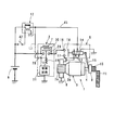
- the relay 2 the configuration of the motor energizing relay 2 (hereinafter referred to as the relay 2) will be described in detail with reference to FIG.
- the relay 2 includes a resistor 7, a relay contact (to be described later) that can connect the battery 6 and the motor 3 by bypassing the resistor 7, and a relay coil 19 that forms an electromagnet when energized.
- the relay contact is opened and closed according to the excitation state of the coil 19.
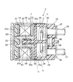
- the relay 2 includes a relay case 20 that also serves as a magnetic circuit (yoke), a resin bobbin 33, the relay coil (coil body) 19 accommodated in the relay case 20, and the relay coil 19. And a magnetic plate 21 made of metal such as iron, which is disposed adjacent to one end side (the left side in the figure).
- the relay 2 includes a movable iron core 22 provided inside the relay coil 19 so as to be movable along the axial direction thereof, a partition member 23 disposed adjacent to the other end of the relay coil 19, and a movable iron core. 22 and a fixed iron core 24 arranged to face each other in the axial direction.
- the relay 2 includes a resin contact cover 25 fixed to the relay case 20 in a state in which an opening described later of the relay case 20 is closed, and first and second external connections fixed to the contact cover 25. Terminals 26 and 27, and first and second fixed contacts 28 and 29 connected to the battery 6 and the fixed contact 16 through the first and second external connection terminals 26 and 27, respectively.
- the relay 2 includes the movable contact 30 that electrically connects between the first and second fixed contacts 28 and 29 and the resistor that is electrically connected between the two external connection terminals 26 and 27. 7, a control circuit 31 that controls the excitation state of the relay coil 19, a contact pressure spring 40, and the like.
- the relay case 20 has a substantially cylindrical shape, and has a flat bottom portion 20a on one end side (the left side in the drawing) along the central axis direction and an opening portion opened on the other end side in the axial direction. .
- the left side is described as one end side and the right side is described as the other end side.
- the relay case 20 is manufactured, for example, by drawing.
- the relay case 20 is formed such that the inner diameter on the other end side (opening side) is slightly longer than the inner diameter on one end side (bottom 20a side) in the axial direction in which the relay coil 19 is housed.
- a step is provided at the boundary.
- a metal bracket 32 is mechanically joined to the outer surface of the bottom 20a of the relay case 20 by welding or the like.
- the motor energizing relay 2 is fixed to the housing (not shown) of the starter 1 via the bracket 32.
- the bobbin 33 has a hollow cylindrical body portion, and has first and second flanges at both axial end portions thereof.
- the bobbin 33 is coaxially accommodated in the relay case 20, and the first flange is in contact with or close to the magnetic material plate 21.
- the relay coil 19 is configured by winding a conducting wire around a bobbin 33. As shown in FIG. 3, the end of one conducting wire on the high potential side is connected to the control circuit 31 and is on the low potential side. The other end of the conducting wire is connected to the ground via a relay case 20 that is a magnetic material.
- the magnetic plate 21 constitutes, for example, a first partition member described in the invention according to claim 2.
- the magnetic plate 21 has, for example, a plate thickness substantially the same as that of the relay case 20 and is formed in an annular shape having a round hole (cylindrical opening) in the central portion in the radial direction.
- the magnetic plate 21 forms a radial magnetic path (a part of the magnetic circuit) between the relay case 20 and the movable iron core 22.
- the inner diameter of the round hole is slightly larger than the outer diameter of the movable core 22 so that the movable core 22 can move in the axial direction.
- the inner diameter of the cylindrical opening of the magnetic plate 21 is substantially the same as the diameter of the inner peripheral portion of the bobbin 33, and the cylindrical opening of the magnetic plate 21 and the inner peripheral opening of the bobbin 33 are mutually. It communicates along the axial direction.
- the movable iron core 22 has, for example, a substantially cylindrical shape, and is provided movably along the axial direction of the bobbin 33 in the opening of the magnetic body plate 21 and the opening on the inner peripheral side of the bobbin 33.
- the movable iron core 22 has, for example, a cross-sectional shape (cross-sectional shape shown in FIG. 1) that is cut in the axial direction through the center in the radial direction is formed in an H shape, and cylindrical recesses (grooves) are formed on both sides in the axial direction. Have. Further, the end of one end side of the movable iron core 22 that faces the bottom 20a protrudes from the magnetic plate 21 toward the bottom 20a.
- a spacer member 34 formed of a non-magnetic material is disposed between the bottom 20a of the relay case 20 and the movable iron core 22 and the magnetic material plate 21.
- the spacer member 34 can be disposed only between the bottom 20a of the relay case 20 and the movable iron core 22. That is, the spacer member 34 may not be provided between the bottom 20a of the relay case 20 and the magnetic plate 21, and a gap (space) may be provided between the bottom 20a of the relay case 20 and the magnetic plate 21. good.
- the magnetic plate 21 may be brought into contact with the bottom 20a of the relay case 20 by increasing the thickness of the magnetic plate 21.
- the partition member 23 constitutes, for example, the second partition member described in the invention according to claim 2.
- the partition member 23 is made of, for example, metal such as iron, and is formed in an annular shape having a plate thickness thicker than that of the relay case 20 and having a cylindrical opening at a central portion in the radial direction.
- the coil side end portion (the end portion on the left side of the outer periphery portion in FIG. 1) in the thickness direction at the outer periphery portion is in contact with the step provided on the inner periphery of the relay case 20.
- the second flange is joined to the coil side end face of the partition wall member 23.
- the partition member 23 regulates the positions of the coil 21 and the surrounding members in the relay 2.
- the partition member 23 forms a magnetic path (a part of the magnetic circuit) in the radial direction from the inner periphery of the relay case 20.
- the fixed iron core 24 is continuously provided integrally with the inner peripheral portion of the partition wall member 23, protrudes from the partition wall member 23 toward the movable iron core 22 along the axial direction thereof, and is formed in the relay coil 19 (bobbin 33). It is arranged so as to enter the circumferential opening and to face the movable iron core 22 along its axial direction.
- the inner diameters of the cylindrical openings of the partition wall member 23 and the fixed iron core 24 substantially match the inner diameters of the cylindrical recesses of the movable iron core 22, and the cylindrical openings of the fixed iron core 24 and the cylindrical recesses of the movable iron core 22 Are opposed to each other along the axial direction.
- the partition wall member 23 and the fixed iron core 24 are not necessarily provided integrally, and may be provided electrically and mechanically so that both are provided separately and a continuous magnetic path is formed. good.
- the partition wall member 23 and the fixed iron core 24 are collectively referred to as a magnetic circuit component.
- the magnetic circuit component is molded (inserted) into a resin member 33 a formed integrally with the bobbin 33 together with the control circuit 31, for example, and is integrated with the bobbin 33.
- cylindrical opening of the partition wall member 23 and the fixed iron core 24 in the magnetic circuit component parts constitutes a through hole for passing a shaft 35 described later.
- the contact cover 25 has a substantially hollow cylindrical shape, and has a cylindrical leg 25a at one end along the axial direction and a bottom at the other end.
- the leg portion 25a is assembled in the relay case 20 with its distal end inserted into the opening of the relay case 20 and in contact with the outer edge portion of the end surface of the partition member 23 on the opposite coil side (right side in FIG. 1).
- the contact cover 25 is fixed in the relay case 20 by caulking the open end of the relay case 20 over a part or the entire circumference of the leg portion 25a.
- the space between the contact cover 25 and the relay case 20 is sealed by, for example, a seal member 36 such as an O-ring to prevent intrusion of water or the like from the outside.
- a seal member 36 such as an O-ring to prevent intrusion of water or the like from the outside.
- the first external connection terminal 26 is connected to the positive terminal of the battery 6 via a cable.
- the second external connection terminal 27 is connected to the B terminal bolt of the electromagnetic switch 5 via, for example, a metal connecting member or a cable.
- each of the first and second external connection terminals 26 and 27 has a bolt shape, a bolt head is disposed inside the contact cover 25, and is formed at the bottom of the contact cover 25.
- a bolt screw portion is projected to the outside of the contact cover 25 through the formed through hole, and is fixed to the contact cover 25 by washers 37 and 38.
- the relay contact is composed of first and second fixed contacts 28 and 29.
- the first fixed contact 28 is disposed in an internal space (hereinafter referred to as a contact chamber 39) of the contact cover 25 formed on the side opposite to the coil from the partition member 23, and is electrically connected to the first external connection terminal 26. And mechanically fixed.
- the second fixed contact 29 is disposed in the contact chamber 39, is electrically connected to the second external connection terminal 27, and is mechanically fixed.
- the first and second fixed contacts 28 and 29 can be provided integrally with the bolt heads of the first and second external connection terminals 26 and 27, for example.
- the movable contact 30 is arranged on the other end side in the axial direction from the first and second fixed contacts 28 and 29, and receives the load of the contact pressure spring 40 when the relay coil 19 is de-energized.
- the fixed contacts 28 and 29 are pressed and contacted (that is, the relay 2 is closed (see FIG. 1)).
- the relay coil 19 when the relay coil 19 is excited, the movement of the movable iron core 22 attracted by the fixed iron core 24 is transmitted through the shaft 35, so that the movable contact 30 compresses the contact pressure spring 40 in the axial direction. It moves to the other end side (the right side in FIG. 1) and moves away from the first and second fixed contacts 28 and 29 (that is, the relay 2 is opened).
- the motor energizing relay 2 of the present embodiment has a normally closed contact structure in which the relay contact is closed when the relay coil 19 is not excited, as shown in FIG.
- the resin member 33a is formed in an annular shape having a cylindrical opening at the radial center.
- the guide member 33b is, for example, continuously provided integrally with the inner peripheral portion of the resin member 33a, protrudes along the axial direction from the resin member 33a toward the movable iron core 22, and is formed as a magnetic circuit component. It is fitted in the through hole.
- the shaft 35 is provided separately from the movable iron core 22 and is formed of a resin member.
- the shaft 35 is inserted into the cylindrical opening of the guide member 33b and disposed in the axial direction.
- a flange portion 35a is provided at an end portion on one end side of the shaft 35, and the flange portion 35a is formed in the movable iron core 22 and is fitted in one recess facing the flange portion 35a. Further, the end face on the other end side of the shaft 35 does not come into contact with the movable contact 30 when the relay coil 19 is not excited, and a slight gap is secured between the end face and the movable contact 30 as shown in FIG. Has been. However, if the contact pressure spring 40 does not affect the contact pressure applied between the movable contact 30 and the first and second fixed contacts 28, 29, that is, if the contact pressure does not decrease, the shaft 35 The end face on the other end side may be in light contact with the surface of the movable contact 30.
- the movable iron core 22 is set on the set side (reverse to the fixed iron core 24) in the gap between the inner circumference of the through hole of the magnetic circuit component and the outer circumference of the shaft 35 and the gap between the flange portion 35a and the guide member 33b.
- a return spring 41 is provided for pulling away in the direction of the fixed iron core.
- One end of the return spring 41 is supported by the flange portion 35a of the shaft 35, and the other end is supported by the axial end surface of the guide member 33b.
- the shaft 35 is pressed against the movable iron core 22 by the load of the return spring 41 in a state where the flange portion 35 a is fitted in the concave portion of the movable iron core 22.
- the resistor 7 has a function of suppressing an inrush current generated when the main contact of the electromagnetic switch 5 described above is closed. That is, the resistor 7 is disposed in the contact chamber 39, and one end is electrically and mechanically joined to the bolt head of the first external connection terminal 26, and the other end is It is electrically and mechanically joined to the bolt head of the second external connection terminal 27.
- the resistor 7 is not in contact with the outer peripheral surface of the shaft 35, and the resin contact cover 25 and the resin member 33a are not thermally damaged when the resistor 7 is heated red.
- the contact cover 25 is disposed in a state in which a predetermined space is secured between the inner peripheral surface of the contact cover 25 and the surface of the resin member 33a.
- the resistor 7 includes an end 7 a that is electrically and mechanically joined to a bolt head of the first external connection terminal 26, and a bolt head of the second external connection terminal 27.
- the other end portion 7b that is electrically and mechanically joined to each other, and the connection portion 7c that continuously connects the one end portion 7a and the other end portion 7b.
- the connecting portion 7c extends between the one end portion 7a and the other end portion 7b so as to bypass the shaft 35 and to secure a predetermined space with respect to the inner peripheral surface of the contact cover 25 and the surface of the resin member 33a.
- control circuit 31 is electrically connected to a power supply line L ⁇ b> 1 that supplies power from the battery 6 to the relay coil 19, and is disposed upstream of the relay coil 19.
- the control circuit 31 is electrically connected to the start switch 42 via a signal line L2 for transmitting a trigger signal for starting the control circuit 31.
- the control circuit 31 is configured by an IC, for example. That is, the control circuit 31 includes an internal circuit element and a package P that protects the internal circuit element.
- the control circuit 31 is disposed in the relay case 20 so that the package P is in close contact with the surface of the partition member 23, and as described above, the resin member formed integrally with the bobbin 33 together with the magnetic circuit components.
- the control circuit 31 and the magnetic circuit components are molded by the resin constituting the resin member 33a and the bobbin 33).
- the control circuit 31 may be disposed in the relay case 20 so that the package P is in close contact with the surface of the partition wall member 23.
- the control circuit 31 is mounted on the surface of the partition wall member 23 on the opposite coil side (the right side in the drawing) and molded on the resin member 33a.
- it can be mounted on the surface of the partition wall member 23 on the coil side (the left side in the drawing) and molded by the second flange portion of the bobbin 33.
- the start switch 42 shown in FIG. 3 When the start switch 42 shown in FIG. 3 is turned on, the starter relay 12 is closed and a trigger signal is transmitted to the control circuit 31, and a drive signal is output from the control circuit 31 to the motor energization relay 2.
- the start switch 42 is, for example, in a vehicle equipped with a manual operation by a user or an idle stop device (Idle reduction system, a device that automatically controls engine stop and restart), and the engine is operated after the idle stop is performed.
- the user tries to start the vehicle after stopping (the engine output shaft stops rotating) or during the deceleration period until it stops (for example, releasing the brake, shifting to the drive range, etc.) It is turned on when the operation is performed.
- the pinion 10 may be smoothly meshed with the ring gear 11 without being abutted, but it is probable that it is extremely small and usually abuts against the end face of the ring gear 11.
- the drive signal for the relay 2 is turned on for a predetermined time predetermined by the control circuit 31, and then turned off.
- the relay coil 19 is excited by the drive signal in the on state. Due to the excitation of the relay coil 19, the movable iron core 22 moves to the other end side (the right side in FIG. 1) against the urging force of the return spring 41, and as a result, the shaft 35 moves to the other end side of the relay 2.
- the movable contact 30 is pressed to the other end side of the relay 2 and moved to the other end side of the relay 2 against the urging force of the return spring 40. As a result, the movable contact 30 is separated from the fixed contacts 28 and 29. That is, the relay contact of the relay 2 is opened (off).
- the motor 3 rotates at a low speed due to the suppression current flowing through the motor 3.
- the pinion 10 that is in contact with the ring gear 11 meshes with the ring gear 11.
- the drive signal for the motor energizing relay 2 is turned off.
- the relay coil 19 is de-energized, and the movable iron core 22 is pulled away from the fixed iron core 24 by the urging force of the return spring 41 and moves to one end side (set side) of the relay 2.
- the shaft 35 moves to one end side of the relay 2 by the movement of the fixed iron core 24, the pressing force from the shaft 35 to the movable contact 30 is released.
- the movable contact 30 moves to one end side of the relay 2 by the urging force of the contact pressure spring 40 and comes into contact with the fixed contacts 28 and 29, and the relay contact of the relay 2 is closed (turned on).
- the energization path for short-circuiting both ends of the resistor 7 is formed by closing the relay contact.
- the relay 2 incorporates the control circuit 31 for turning on and off the relay 2. That is, in the present embodiment, the control circuit 31 is housed inside the housing of the motor energizing relay 2 that is configured by the relay case 20 and the contact cover 25. As a result, it is possible to eliminate the need for a housing dedicated to the control circuit, to reduce the number of connection points such as connectors for wiring between the control circuit 31 and the relay 2, and to simplify the wiring around the relay 2. 2 reliability can be improved.
- control circuit 31 in the relay 2, electrical connection between the control circuit 31 and the relay coil 19 can be facilitated, and an installation space for the control circuit 31 can be secured separately from the relay 2. Since it is not necessary, the mountability can be improved.
- control circuit 31 when the control circuit 31 is installed separately from the relay 2 (the control circuit 31 is disposed outside the relay 2), the control circuit 31 and the relay coil 19 are connected by electric wiring, and the electric wiring is exposed to the outside. Therefore, care must be taken in handling the electrical wiring, and there is a risk of disconnection due to external vibration (for example, engine vibration).
- external vibration for example, engine vibration
- the control circuit 31 since an IC is used for the control circuit 31, for example, heat resistance is improved as compared with a substrate circuit in which a plurality of circuit elements are mounted on a substrate. Further, since the package P of the control circuit 31 is attached in close contact with the metal partition member 23 having heat dissipation, heat generated due to circuit loss (Joule heat) can be radiated to the partition member 23, and the circuit It is possible to improve the service life and extend the energization time. Further, by molding the control circuit 31 together with the partition wall member 23 on the resin member 33a formed integrally with the bobbin 33, the control circuit 31 can be securely fixed, and abrasion powder or the like of the relay contacts is accumulated between the IC terminals. Therefore, it is possible to prevent a decrease in insulation between the IC terminals due to the wear powder.
- the environmental resistance of the control circuit 31 can be improved, and the relay 2 can be actively used even under severe conditions of environmental temperature and vibration.
- the control circuit 31 shown in the first embodiment is electrically connected to the power supply line L ⁇ b> 1 that supplies power from the battery 6 to the relay coil 19, and is electrically connected to the relay coil 19. It is arranged on the upstream side. According to this configuration, the control circuit 31 is connected between the power input terminal and the relay coil 19 without significantly changing the signal path of the power input terminal, the signal input terminal of the relay coil 19, and the ground terminal of the relay coil 19. Since it functions only by interrupting in between, the control circuit 31 of the present invention can be easily applied to a similar electromagnetic relay.
- the second embodiment uses an IC for the control circuit 31 and, as shown in FIG. It is attached in close contact with the surface (left side of the figure).
- the control circuit 31 is molded by a resin spacer member 34 (the control circuit 31 is molded by a resin constituting the resin spacer member 34).
- the magnetic plate 21 is made of metal such as iron and has a heat dissipation property, similarly to the partition wall member 23 described in the first embodiment, so that the package P of the IC (control circuit 31) is made magnetic.
- the package P of the IC control circuit 31
- the magnetic plate 21 is made of metal such as iron and has a heat dissipation property, similarly to the partition wall member 23 described in the first embodiment, so that the package P of the IC (control circuit 31) is made magnetic.
- heat generated by the loss of the control circuit 31 can be radiated to the magnetic body plate 21, so that the life of the control circuit can be improved and the energization time for the relay 2 can be extended.
- control circuit 31 can be securely fixed, and the abrasion powder of the relay contacts does not accumulate between the IC terminals. It is possible to prevent a decrease in insulation between the IC terminals due to powder.
- the environmental resistance of the control circuit 31 can be improved, and the relay 2 can be actively used even under severe conditions of environmental temperature and vibration.
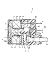
- the relay 2 according to the third embodiment has a so-called normally open contact structure in which the relay contact is closed when the relay coil 19 is excited.
- the positional relationship between the fixed iron core 24 and the movable iron core 22 is reversed in the axial direction of the relay 2.
- the cylindrical fixed iron core 24 is disposed so that the flange portion on one end side thereof is mounted on the surface of the coil side (right side in the drawing) of the disk-shaped metal magnetic plate 21, for example.
- the movable iron core 22 is arranged so that one end thereof is opposed to the fixed iron core 24, and is formed in a cylindrical groove portion formed in the other end portion on the enlarged diameter side (a portion whose diameter is larger than the one end portion).
- One end of the shaft 35 is fitted. The end surface of the other end portion of the shaft 35 is in contact with the movable contact 30 biased by the contact pressure spring 40.
- a return spring 41 is provided that urges the movable iron core 22 in the direction of separating the fixed iron core 24 from the non-excited state of the relay coil 19. Yes.
- the movable contact 30 is fixed to the fixed contacts 28 and 29 (FIG. 5 shows only the second fixed contact 29) by the shaft 35 biased via the movable iron core 22.
- it is in a non-contact state (relay contact is open).
- the movable iron core 22 when the relay coil 19 is excited, the movable iron core 22 is attracted to the fixed iron core 24 against the reaction force of the return spring 41 between the movable iron core 22 and the fixed iron core 24. (Moving to the left in the figure), the movable contact 30 biased by the contact pressure spring 40 contacts the first and second fixed contacts 28 and 29 to close the relay contact.
- the relay coil 19 when the relay coil 19 is not energized, the movable iron core 22 is pushed back to the set side (anti-fixed iron core direction) by the reaction force of the return spring 41, and the movable contact 30 resists the reaction force of the contact pressure spring 40.
- the relay contact is opened by separating from the first and second fixed contacts 28 and 29.
- control circuit 31 can use an IC, is attached in a state where the package P of the IC is in close contact with the surface of the magnetic plate 21 on the side opposite to the fixed core, and the bobbin
- the resin member 33 a formed integrally with the resin 33 is molded.
- Reference numeral 43 in FIG. 5 represents an external terminal that is taken out of the contact cover 25.
- the external terminal 43 is electrically connected to the control circuit 31, and is connected between the control circuit 31 and the outside. It is possible to send and receive signals.
- the control circuit 31 is housed inside the housing of the motor energizing relay 2, Similar effects can be obtained.
- the IC package P is attached in close contact with the metal magnetic plate 21 and is molded together with the magnetic plate 21 into the resin member 33a.
- the relay 2 can be actively used even under severe conditions of environmental temperature and vibration.
- the fourth embodiment is another example in which the control circuit 31 (IC) is housed inside the casing of the normally open contact structure relay 2 as in the third embodiment, and is taken out of the contact cover 25. It has a feature in a signal transmission path for transmitting a signal inputted through the external terminal 43 to the control circuit 31.
- the signal transmission path is formed by a signal transmission terminal 44 provided integrally with the external terminal 43, and this signal transmission terminal 44 is a cylinder of the bobbin 33 that supports the inner diameter of the relay coil 19. Secondary molding is performed inside the body.
- the control circuit 31 is composed of an IC as in the third embodiment, and the package P is resin-molded together with the magnetic plate 21 in a state of being in close contact with the magnetic plate 21.
- the terminal 31 a taken out from the control circuit 31 is electrically connected to the end of the signal transmission terminal 44.
- the signal transmission terminal 44 is molded inside the cylindrical body portion of the bobbin 33, and a signal transmission path from the external terminal 43 to the control circuit 31 can be formed via the signal transmission terminal 44.
- the motor energizing relay 2 can be reduced in size.
- the external terminal 43 and the signal transmission terminal 44 are integrally provided, but a configuration in which both are formed separately and electrically coupled may be employed.
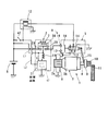
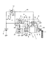
- the control circuit 31 is connected to the upstream side of the relay coil 19 with respect to the power supply line L1 for supplying power from the battery 6 to the relay coil 19. As shown in FIG. 7, the control circuit 31 is connected to the power line L ⁇ b> 1 of the relay coil 19 on the downstream side of the relay coil 19. The control circuit 31 is energized via a branch line B branched from the power supply line L1.
- a switching element 47 for controlling the excitation state of the relay coil 19 is connected between the end of the low-potential side conductor of the relay coil 19 and the ground terminal. Is intervening. That is, when the control circuit 31 that has received the trigger signal turns on the switching element 47, the relay coil 19 can be excited, and by turning off the switching element 47, the relay coil 19 can be de-energized. .
- the current flowing out of the relay coil 19 can flow from the ground terminal of the control circuit 31 to the ground side. That is, since the ground terminal of the control circuit 31 and the ground terminal of the relay coil 19 can be shared, the number of terminals can be reduced.
- a power supply line for supplying power to the control circuit 31, a power supply line for supplying power to the relay coil 19, and the control circuit 31 are activated.
- the signal line for transmitting the trigger signal is shared, and the common line L3 is connected to the energization line 45 for energizing the excitation coil 13 of the electromagnetic switch 5 from the battery 6 via the starter relay 12, and from this energization line 45
- power is supplied to the control circuit 31 and the relay coil 19 through the common line L3, and a trigger signal is captured.
- the power supply dedicated line can be omitted, so that the number of terminals of the motor energization relay 2 can be reduced and simplified.
- the motor energization relay 2 functions only by supplying a branch signal from the energization line 45 of the electromagnetic switch 5 without significantly changing the conventional vehicle wiring.
- control circuit 31 is arranged on the upstream side of the relay coil 19 as shown in FIG. 8, or the control circuit 31 is arranged on the downstream side of the relay coil 19 as shown in FIG. It can also be arranged.
- a diode can be used as the surge absorbing element 46, the cathode side thereof is connected to the common line L3, and the anode side is connected to the end of the low potential side conductor of the relay coil 19.
- the diode 46 has a function of absorbing a surge generated when the relay coil 19 is turned off, that is, when the starter relay 12 provided in the conduction line 45 is opened.
- the MOSFET 47 is a switching element for controlling the excitation state of the relay coil 19, and a surge that flows from the excitation coil 13 of the electromagnetic switch 5 through the energization line 45 to the control circuit 31 is formed in the MOSFET 47. It can be absorbed by the parasitic diode 47a.
- the control circuit 31 of the present embodiment is one of a starting current suppression prohibiting function F1, a temperature protection function F2, an overcurrent protection function F3, and a resistor energization time adjustment function F4 described below. It has one function or multiple functions. In FIG. 11, the control circuit 31 is illustrated as having all the above four functions. However, as described above, the control circuit 31 may have any one function.
- the start-up current suppression prohibiting function F1 is performed when the motor 3 This is a function for prohibiting the function of suppressing the start-up current.
- the start current suppression prohibiting signal is transmitted from the external device D of the relay 2, for example, from the ECU, the motor 3 is not energized via the resistor 7 when the motor 3 is started. The relay contact is closed, and the motor 3 is energized by the full voltage of the battery 6. Thereby, the startability of the engine is improved even when the engine is difficult to start.
- the temperature protection function F2 has, for example, a function of detecting the temperature of the control circuit 31 itself or its surroundings. As a result, when an abnormal temperature exceeding a preset allowable temperature is detected, the temperature protection function F2 is supplied to the control circuit 31. It is a function that cuts off the electric power by itself, and can prevent the circuit failure from being induced by using the control circuit 31 at an abnormal temperature.
- the overcurrent protection function F3 is a function that cuts off the electric power supplied to the control circuit 31 when an overcurrent exceeding a preset allowable current flows, and a circuit formed by the overcurrent flowing to the billing control circuit 31. Induction of failure can be prevented.
- Resistor energization time adjustment function F4 is a function that can adjust the energization time to the resistor 7 when the motor 3 is energized via the resistor 7 when the motor 3 is started. For example, when it is determined from the detection signal of the temperature sensor of the starter 1 that is the external device D of the relay 2 that the starter 1 is at a high temperature exceeding a predetermined temperature, the energization time to the resistor 7 (the relay contact is opened) Extend the time). As a result, the starter current can be supplied in a balanced manner so that the startability of the engine can be improved and the voltage drop of the battery 6 caused by the starter current can be suppressed.
- control circuit 31 is disposed in the contact chamber 39 and includes at least a temperature protection function F2 among the four functions described in the eighth embodiment.
- the control circuit 31 receives radiant heat radiated from the resistor 7 when the resistor 7 is energized.
- the control circuit 31 may be connected to the resistor 7 as shown in FIG. 2, FIG. 4, FIG. 5, or FIG. 6, for example, to prevent failure before the temperature protection function is activated due to the heat generated by the resistor 7.
- the resistor 7 are arranged with an appropriate distance between them. In other words, when the resistor 7 generates heat, it is arranged in a region where the temperature protection function functions effectively.
- the temperature protection function F2 functions to the control circuit 31. Is interrupted. As a result, the operation of the control circuit 31 is stopped and the drive signal to the relay coil 19 is interrupted, so that the relay contact is closed and an energization path that bypasses the resistor 7 is formed. As a result, since the current flowing through the resistor 7 is limited, heat generation of the resistor 7 is suppressed, and the resistor 7 can be prevented from fusing due to abnormal heat generation.
- the resistor 7 is not blown, so it is not necessary to replace the resistor 7, it can be used as it is, and the control circuit 31 is not broken. Functions normally.
- the relay case 20 of the relay 2 has a bottomed cylindrical shape, but the outer peripheral shape does not necessarily have a cylindrical shape, and the cross-sectional shape orthogonal to the axial direction is a polygonal shape (for example, a rectangle, a hexagon, etc.). May be.
- the relay 2 is provided upstream of the main contact of the electromagnetic switch 5. However, it can be provided downstream of the main contact, that is, between the M terminal bolt and the motor 3. is there.
Abstract
Disclosed is an electromagnetic relay for activating a motor of a starter, the electromagnetic relay comprising a resistor for reducing starter current that flows from the battery to the motor when starting the motor; a relay contact point for bypassing the resistor and causing the starter current to flow; a relay coil that is excited by electricity and forms an electromagnet; and a control circuit that controls the electricity to the motor from the battery via the resistor by controlling the state of excitation of the relay coil and opening and closing the relay contact point when starting the motor. The electromagnetic relay houses the control circuit therewithin.
Description
本発明は、スタータのモータ回路に設けられた電磁継電器に係わり、特に、エンジン始動時にモータの起動電流を抑制するための抵抗体を内蔵し、モータの起動後に抵抗体をバイパスして、バッテリの全電圧によりモータに通電する電磁継電器に関する。
The present invention relates to an electromagnetic relay provided in a motor circuit of a starter, and in particular, includes a resistor for suppressing a motor starting current when starting an engine, bypassing the resistor after starting the motor, The present invention relates to an electromagnetic relay that energizes a motor with all voltages.
従来、エンジンを始動するスタータは、ピニオンをリングギヤ側へ押し出す働きと、モータ回路(バッテリからモータに電流を流すための回路)に設けられるメイン接点を開閉する働きとを行う電磁スイッチを搭載している。
Conventionally, a starter for starting an engine is equipped with an electromagnetic switch that pushes a pinion toward the ring gear and opens and closes a main contact provided in a motor circuit (a circuit for flowing current from a battery to a motor). Yes.
ところで、モータの起動時、つまり、電磁スイッチがメイン接点を閉じた時に、バッテリから突入電流と呼ばれる大電流がモータに流れる。この突入電流の発生により、バッテリの端子電圧が大きく低下して、メータ類やオーディオ等の電気機器が瞬間的に作動停止する、いわゆる「瞬断」と言われる現象が発生することがある。
By the way, when the motor is started, that is, when the electromagnetic switch closes the main contact, a large current called an inrush current flows from the battery to the motor. Occurrence of this inrush current may cause a phenomenon called so-called “instantaneous interruption” in which the terminal voltage of the battery is greatly reduced, and electric devices such as meters and audio are instantaneously stopped.
これに対し、本出願人は、モータの起動時に流れる突入電流を抑制して、「瞬断」の発生を防止できる技術を提案している(特許文献1参照)。
On the other hand, the present applicant has proposed a technique capable of preventing the occurrence of “instantaneous interruption” by suppressing the inrush current that flows when the motor starts.
この特許文献1に係る発明は、図12に示す様に、スタータ100に搭載される電磁スイッチ101とは別に、モータ回路を開閉できるモータ通電用リレー102(電磁継電器)を備えている。このモータ通電用リレー(リレー)102は、図13に示す様に、2本の端子ボルト103、104を介してモータ回路に接続される抵抗体105と、この抵抗体105の上流端と下流端との間に、一組の固定接点によって構成されるリレー接点106とを備えている。リレー102は、リレーコイル107の励磁状態に応じて可動する可動接点108によりリレー接点106を開閉する働きを有している。リレーコイル107の励磁状態は、制御回路109(図12参照)より出力される駆動信号によって制御される。例えば、制御回路109の駆動信号がオンの時に、リレーコイル107が励磁されてリレー接点106を閉成(オン)し、制御回路109の駆動信号がオフの時に、リレーコイル107が非励磁となってリレー接点106を開成(オフ)する。
As shown in FIG. 12, the invention according to Patent Document 1 includes a motor energizing relay 102 (electromagnetic relay) that can open and close a motor circuit, in addition to the electromagnetic switch 101 mounted on the starter 100. As shown in FIG. 13, the motor energization relay (relay) 102 includes a resistor 105 connected to the motor circuit via two terminal bolts 103 and 104, and an upstream end and a downstream end of the resistor 105. And a relay contact 106 constituted by a set of fixed contacts. The relay 102 has a function of opening and closing the relay contact 106 by a movable contact 108 that can move according to the excitation state of the relay coil 107. The excitation state of the relay coil 107 is controlled by a drive signal output from the control circuit 109 (see FIG. 12). For example, when the drive signal of the control circuit 109 is on, the relay coil 107 is excited to close (turn on) the relay contact 106, and when the drive signal of the control circuit 109 is off, the relay coil 107 is de-energized. Then, the relay contact 106 is opened (turned off).
モータ110の起動時には、制御回路109の駆動信号がオフであり、リレーコイル107が非励磁でリレー接点106が開いている。図12に示すように、この状態で、電磁スイッチ101がメイン接点111を閉成すると、抵抗体105により抑制された電流がモータ110に流れるため、モータ110が低速度で回転する。その後、つまり、スタータ100のピニオン112がエンジン側のリングギヤ113に噛み合った後、駆動信号がオフからオンに切り替わる。その結果、リレーコイル107が励磁されてリレー接点106が閉成することにより、抵抗体105の両端がリレー接点106を介して短絡される。この抵抗体105の両端の短絡により、バッテリ114の全電圧がモータ110に印加されて、起動時より高い電流がモータ110に流れることにより、モータ110の回転速度が上昇する。
When the motor 110 is started, the drive signal of the control circuit 109 is off, the relay coil 107 is not excited, and the relay contact 106 is open. As shown in FIG. 12, in this state, when the electromagnetic switch 101 closes the main contact 111, the current suppressed by the resistor 105 flows to the motor 110, so the motor 110 rotates at a low speed. After that, after the pinion 112 of the starter 100 is engaged with the ring gear 113 on the engine side, the drive signal is switched from OFF to ON. As a result, the relay coil 107 is excited and the relay contact 106 is closed, whereby both ends of the resistor 105 are short-circuited via the relay contact 106. Due to the short circuit between both ends of the resistor 105, the entire voltage of the battery 114 is applied to the motor 110, and a higher current flows through the motor 110 than at the time of startup, thereby increasing the rotational speed of the motor 110.
図12に示した様に、制御回路109をモータ通電用リレー102とは別に、車室内や車室外に設置する場合は、制御回路109を内蔵するための専用の筐体を準備する必要がある。さらに、制御回路109とバッテリ114とを電源線を介して接続し、かつ該制御回路109とモータ通電用リレー102とを信号線を介して接続することにより、モータ通電用リレー102へ駆動信号を送信可能にする必要がある。この場合、電源線、信号線、及び、モータ通電用リレー102を駆動するための配線が必要であると共に、コネクタ等の接続部位が増加する要因となっている。
As shown in FIG. 12, when the control circuit 109 is installed in the vehicle interior or the exterior of the vehicle separately from the motor energization relay 102, it is necessary to prepare a dedicated housing for incorporating the control circuit 109. . Further, by connecting the control circuit 109 and the battery 114 via a power supply line and connecting the control circuit 109 and the motor energization relay 102 via a signal line, a drive signal is sent to the motor energization relay 102. Must be sendable. In this case, wiring for driving the power supply line, the signal line, and the motor energizing relay 102 is necessary, and this increases the number of connection parts such as connectors.
さらに、制御回路109を車室外に設置する場合は、制御回路109を雨水等から保護するために、制御回路109を内蔵する筐体の防水構造が必要となる。
Furthermore, when the control circuit 109 is installed outside the passenger compartment, a waterproof structure for the housing containing the control circuit 109 is required to protect the control circuit 109 from rainwater and the like.
本発明は、上記事情に基づいて成されたもので、その一態様の目的は、「瞬断」を防止するための抵抗体通電制御用の制御回路を用いた電磁継電器の信頼性を高く維持することにある。
The present invention has been made based on the above circumstances, and an object of one aspect thereof is to maintain high reliability of an electromagnetic relay using a resistor energization control circuit for preventing “instantaneous interruption”. There is to do.
特に、本発明の他の態様の目的は、「瞬断」を防止するための抵抗体通電制御用の制御回路を用いた電磁継電器の耐環境性を高く維持することにある。
Particularly, an object of another aspect of the present invention is to maintain high environmental resistance of an electromagnetic relay using a control circuit for resistance energization control for preventing “instantaneous interruption”.
請求項1に係る発明によれば、スタータのモータを起動するための電磁継電器であって、前記モータを起動する際に、バッテリから前記モータに流れる起動電流を抑制するための抵抗体と、この抵抗体をバイパスして前記起動電流を流すためのリレー接点と、通電によって励磁されて電磁石を形成するリレーコイルと、前記モータの起動時に前記リレーコイルの励磁状態を制御して前記リレー接点を開閉することにより、前記バッテリから前記抵抗体を経由して前記モータへの通電を制御する制御回路とを備え、前記電磁継電器は、前記制御回路を内蔵する。
According to the first aspect of the present invention, there is provided an electromagnetic relay for starting a starter motor, and a resistor for suppressing a starting current flowing from a battery to the motor when the motor is started, A relay contact for bypassing the resistor to flow the starting current, a relay coil that is excited by energization to form an electromagnet, and controls the excitation state of the relay coil when the motor is started to open and close the relay contact And a control circuit for controlling energization of the motor from the battery via the resistor, and the electromagnetic relay incorporates the control circuit.
上記の構成によれば、制御回路を電磁継電器に内蔵することで、制御回路専用の筐体を必要としない。このため、配線を接続するためのコネクタ等の接続個所を減らすことができ、且つ、電磁継電器周りの配線を簡素化できるので、信頼性の向上につながる。
に よ According to the above configuration, the control circuit is built in the electromagnetic relay, so that a housing dedicated to the control circuit is not required. For this reason, it is possible to reduce the number of connection points such as connectors for connecting the wirings, and it is possible to simplify the wiring around the electromagnetic relay, leading to an improvement in reliability.
また、制御回路を電磁継電器に内蔵することで、電磁継電器とは別に制御回路の設置スペースを確保する必要がなく、搭載性を向上できる。
In addition, by incorporating the control circuit in the electromagnetic relay, it is not necessary to secure a space for installing the control circuit separately from the electromagnetic relay, thereby improving the mountability.
請求項2に係る発明は、前記リレーコイルの軸方向に沿った一端側に底部を有し、且つ該軸方向に沿った他端側が開口する開口部を有するケースと、このケースの内部に収容される前記リレーコイルと、このリレーコイルの内部を、該リレーコイルの軸方向に沿って可動する可動鉄心と、前記リレーコイルの軸方向に沿って前記可動鉄心と対向して配置される固定鉄心と、前記リレーコイルの軸方向の一端側と他端側とに配置され、それぞれ磁気回路の一部を形成する第1および第2の隔壁部材と、前記ケースの開口部を閉じた状態で前記ケースに固定される樹脂製のカバーと、前記第2の隔壁部材より反コイル側に形成される前記カバーの内部空間である接点室に配置され、且つ、前記カバーに固定される第1の外部接続端子を介して前記バッテリ側に接続される第1の固定接点と、前記接点室に配置され、且つ、前記カバーに固定される第2の外部接続端子を介して前記モータ側に接続される第2の固定接点と、前記可動鉄心の動きに連動して前記接点室内を軸方向に可動する可動接点と、前記接点室内で前記第1の外部接続端子と前記第2の外部接続端子との間に電気的に接続される前記抵抗体とを備え、前記リレー接点は、前記可動接点が前記第1、第2の固定接点に当接して、両固定接点間が前記可動接点を介して電気的に導通することで閉成し、前記可動接点が前記第1、第2の固定接点から離間することで開成し、前記制御回路は、前記ケースと前記カバーとで構成される筐体の内部に収容される。
According to a second aspect of the present invention, there is provided a case having a bottom portion at one end side along the axial direction of the relay coil and an opening portion opened at the other end side along the axial direction, and accommodated inside the case. The relay coil, a movable iron core that moves inside the relay coil along the axial direction of the relay coil, and a fixed iron core that is disposed facing the movable iron core along the axial direction of the relay coil. And the first and second partition members, which are disposed on one end side and the other end side in the axial direction of the relay coil, respectively forming a part of the magnetic circuit, and the opening of the case is closed A resin cover fixed to the case, and a first external member disposed in a contact chamber that is an internal space of the cover formed on the side opposite to the coil from the second partition member and fixed to the cover Previous through connection terminal A first fixed contact connected to the battery side; a second fixed contact disposed in the contact chamber and connected to the motor side via a second external connection terminal fixed to the cover; Electrically connected between the first external connection terminal and the second external connection terminal in the contact chamber, and a movable contact that is movable in the axial direction in the contact chamber in conjunction with the movement of the movable iron core The relay contact, the movable contact is in contact with the first and second fixed contacts, and the two fixed contacts are electrically connected through the movable contact. The movable contact is opened when the movable contact is separated from the first and second fixed contacts, and the control circuit is accommodated in a housing constituted by the case and the cover.
上記の構成によれば、制御回路を電磁継電器の筐体の内部に収容することで、制御回路とリレーコイルとの電気的な接続を容易に出来る。また、制御回路を電磁継電器とは別に設置する、つまり、電磁継電器の外部に制御回路を配置する場合は、制御回路と電磁継電器のリレーコイルとを電気配線によって接続し、その電気配線が外部に露出する。このため、電気配線の取り回しに注意を要すると共に、外部からの振動(例えば、エンジン振動)により断線する恐れがある。
According to the above configuration, electrical connection between the control circuit and the relay coil can be facilitated by accommodating the control circuit inside the casing of the electromagnetic relay. In addition, when the control circuit is installed separately from the electromagnetic relay, that is, when the control circuit is arranged outside the electromagnetic relay, the control circuit and the relay coil of the electromagnetic relay are connected by electric wiring, and the electric wiring is connected to the outside. Exposed. For this reason, it is necessary to pay attention to the handling of the electrical wiring, and there is a risk of disconnection due to external vibration (for example, engine vibration).
これに対し、請求項2に係る発明によれば、制御回路とリレーコイルとの電気的な接続を電磁継電器の筐体内部で完結できるため、制御回路とリレーコイルとを接続する電気配線を電磁継電器の外部に取り回す必要はなく、振動による断線の恐れもない。また、制御回路を電磁継電器の筐体内部に収容することにより、その電磁継電器の筐体によって防水性を確保できるので、信頼性及び耐環境性を向上できる。
On the other hand, according to the second aspect of the invention, since the electrical connection between the control circuit and the relay coil can be completed inside the casing of the electromagnetic relay, the electrical wiring connecting the control circuit and the relay coil is electromagnetic There is no need to route outside the relay, and there is no fear of disconnection due to vibration. In addition, by housing the control circuit inside the casing of the electromagnetic relay, waterproofness can be ensured by the casing of the electromagnetic relay, so that reliability and environmental resistance can be improved.
請求項3に係る発明は、請求項1または2に記載した電磁継電器において、制御回路は、ICにより構成されていることを特徴とする。
The invention according to claim 3 is the electromagnetic relay according to claim 1 or 2, characterized in that the control circuit is constituted by an IC.
本発明の制御回路にIC(集積回路)を用いることにより、例えば、基板上に複数の回路素子を搭載した基板回路と比較して耐熱性が向上する。その結果、環境温度及び振動の厳しい条件下での電磁継電器の使用が可能となる。
By using an IC (integrated circuit) for the control circuit of the present invention, for example, heat resistance is improved as compared with a substrate circuit in which a plurality of circuit elements are mounted on a substrate. As a result, the electromagnetic relay can be used under conditions of severe environmental temperature and vibration.
また、ICを用いることにより、制御回路の小型化が可能であるため、電磁継電器の限られたスペースにも容易にICを収容でき、制御回路を内蔵した電磁継電器の小型化を図ることができる。
Further, since the control circuit can be miniaturized by using the IC, the IC can be easily accommodated in a limited space of the electromagnetic relay, and the electromagnetic relay incorporating the control circuit can be miniaturized. .
請求項4に係る発明は、請求項3に記載した電磁継電器において、ICは、回路素子を保護するパッケージを有し、このパッケージが、第1の隔壁部材および第2の隔壁部材の内のどちらか一方に密接させた状態で取り付けられていることを特徴とする。
According to a fourth aspect of the present invention, in the electromagnetic relay according to the third aspect, the IC has a package for protecting the circuit element, and the package is one of the first partition member and the second partition member. It is characterized by being attached in close contact with either one.
第1の隔壁部材および第2の隔壁部材の内のどちらか一方は、磁気回路の一部を形成する磁性体であり、例えば鉄等の金属部材により形成されている。このため、ICのパッケージを、金属部材である第1の隔壁部材および第2の隔壁部材の内のどちらか一方に密接させて取り付けることで、回路の損失による発熱(ジュール熱)を第1の隔壁部材および第2の隔壁部材の内のどちらか一方へ放熱することができ、回路の寿命向上、および、通電時間の拡大が可能となる。
One of the first partition member and the second partition member is a magnetic body that forms a part of the magnetic circuit, and is formed of a metal member such as iron. For this reason, the IC package is attached in close contact with either the first partition member or the second partition member, which is a metal member, to generate heat (Joule heat) due to circuit loss in the first Heat can be radiated to one of the partition member and the second partition member, so that the life of the circuit can be improved and the energization time can be extended.
請求項5に係る発明は、請求項4に記載した電磁継電器において、前記リレーコイルは、コイル本体と、このコイル本体が巻回された巻枠である樹脂製のボビンとを備えており、前記ICは、前記パッケージを密接させた前記第1の隔壁部材および前記第2の隔壁部材の内のどちらか一方と共に、前記樹脂製のボビンと一体に形成された樹脂部材にモールドされている。
The invention according to claim 5 is the electromagnetic relay according to claim 4, wherein the relay coil includes a coil body and a resin bobbin that is a winding frame around which the coil body is wound, The IC is molded into a resin member formed integrally with the resin bobbin together with one of the first partition member and the second partition member in close contact with the package.
上記の構成によれば、ICを樹脂部材にモールドすることでICを確実に固定でき、且つ、接点摩耗粉等がIC端子間に堆積することがないので、IC端子間の絶縁低下を防止できる。
According to the above configuration, the IC can be securely fixed by molding the IC on the resin member, and contact wear powder or the like does not accumulate between the IC terminals, so that it is possible to prevent the insulation from being lowered between the IC terminals. .
請求項6に係る発明は、請求項5に記載した電磁継電器において、カバーの外部に取り出される外部端子と、この外部端子を通じて入力される信号をICに伝達する信号伝達ターミナルとを有し、この信号伝達ターミナルは、リレーコイルの内径を支持するボビンの円筒胴体部の内部に二次成形され、ICは、パッケージを第1の隔壁部材に密接させて、その第1の隔壁部材と共にボビンと一体に形成された樹脂部材にモールドされ、信号伝達ターミナルを介して外部端子に結線されていることを特徴とする。
According to a sixth aspect of the present invention, in the electromagnetic relay according to the fifth aspect of the present invention, the electromagnetic relay includes an external terminal that is taken out of the cover, and a signal transmission terminal that transmits a signal input through the external terminal to the IC. The signal transmission terminal is secondarily formed inside the cylindrical body portion of the bobbin that supports the inner diameter of the relay coil, and the IC is integrated with the bobbin together with the first partition member, with the package in close contact with the first partition member. It is molded on a resin member formed in the above, and is connected to an external terminal through a signal transmission terminal.
ICを有底ケースの底面側に配置した場合、つまり、ICを第1の隔壁部材と共に樹脂部材にモールドした構成では、ボビンに巻線した後、ICに結線された被覆付リード線等をリレーコイルの径方向外側に通して外部端子に接続する必要がある。この場合、リレーコイルの径方向外側に被覆付リード線等を通すためのスペースを確保する必要があるため、必然的に径方向の寸法が大きくなり、電磁継電器が大型化する。
When the IC is arranged on the bottom surface side of the bottomed case, that is, in the configuration in which the IC is molded on the resin member together with the first partition member, the coated lead wire connected to the IC is relayed after being wound around the bobbin. It is necessary to connect to the external terminal through the outside in the radial direction of the coil. In this case, since it is necessary to secure a space for passing the coated lead wire or the like on the radially outer side of the relay coil, the dimension in the radial direction is inevitably increased, and the electromagnetic relay is increased in size.
これに対し、請求項6に記載した発明では、ボビンの円筒胴体部の内部に信号伝達ターミナルを通すことにより、その信号伝達ターミナルを介してICと外部端子とを結線できる。この構成では、リレーコイルの径方向外側にスペースを確保する必要がないため、電磁継電器の小型化が可能である。なお、外部端子と信号伝達ターミナルは、別部品でも良いが、両者を一体に設けることも出来る。
On the other hand, in the invention described in claim 6, the IC and the external terminal can be connected via the signal transmission terminal by passing the signal transmission terminal inside the cylindrical body portion of the bobbin. In this configuration, since it is not necessary to secure a space outside the radial direction of the relay coil, the electromagnetic relay can be reduced in size. The external terminal and the signal transmission terminal may be separate parts, but both may be provided integrally.
請求項7に係る発明は、請求項1~6に記載した何れかの電磁継電器において、制御回路は、モータの起動時に抵抗体を経由してモータに通電することなく、リレー接点を閉成して、バッテリの全電圧によりモータに通電する起動電流抑制禁止機能と、予め設定された許容温度を超える異常温度を感知した時に、制御回路に供給される電力を自ら遮断する温度保護機能と、予め設定された許容電流を超える過電流が流れた時に、制御回路に供給される電力を自ら遮断する過電流保護機能と、モータの起動時に抵抗体を経由してモータに通電する際に、抵抗体への通電時間を調整できる抵抗体通電時間調整機能との内の少なくとも1つの機能を備えることを特徴とする。
The invention according to claim 7 is the electromagnetic relay according to any one of claims 1 to 6, wherein the control circuit closes the relay contact without energizing the motor via the resistor when starting the motor. A starting current suppression prohibiting function for energizing the motor with the total voltage of the battery, a temperature protection function for shutting off the power supplied to the control circuit when an abnormal temperature exceeding a preset allowable temperature is detected, An overcurrent protection function that cuts off the power supplied to the control circuit when an overcurrent exceeding the set allowable current flows, and a resistor when the motor is energized via the resistor when the motor starts It is characterized by having at least one of the resistor energization time adjusting functions capable of adjusting the energization time to the resistor.
起動電流抑制禁止機能は、例えば、エンジンの停止および再始動を自動制御するアイドルストップ車両において、システム上、アイドルストップが禁止されている時、言い換えると、エンジンが掛かり難い冷間時に、モータの起動電流を抑制する働きを禁止する。つまり、モータの起動時に抵抗体を経由してモータに通電するのではなく、リレー接点を閉成して、バッテリの全電圧によりモータに通電する。これにより、エンジンが掛かり難い冷間時等においても、エンジン始動性が向上する。
The start-up current suppression prohibition function is, for example, in an idle stop vehicle that automatically controls stop and restart of the engine, when the idle stop is prohibited on the system, in other words, when the engine is cold and it is difficult to start. The function of suppressing the current is prohibited. That is, instead of energizing the motor via the resistor when the motor is started, the relay contact is closed and the motor is energized by the full voltage of the battery. As a result, engine startability is improved even during cold weather when the engine is difficult to start.
温度保護機能は、予め設定された許容温度を超える異常温度を感知した時に、制御回路に供給される電力を自ら遮断することで、回路故障の誘発を防止する。
The temperature protection function prevents the occurrence of a circuit failure by shutting off the power supplied to the control circuit by itself when an abnormal temperature exceeding a preset allowable temperature is detected.
過電流保護機能は、予め設定された許容電流を超える過電流が流れた時に、制御回路に供給される電力を自ら遮断することで、回路故障の誘発を防止する。
The overcurrent protection function prevents the occurrence of a circuit failure by shutting off the power supplied to the control circuit by itself when an overcurrent exceeding a preset allowable current flows.
抵抗体通電時間調整機能は、モータの起動時に抵抗体を経由してモータに通電する際に、抵抗体への通電時間を調整する働きを有する。例えば、スタータの高温時に抵抗体への通電時間(リレー接点が開成している時間)を延長することで、エンジンの始動性を向上でき、且つ、スタータ電流により発生するバッテリの電圧降下を抑制できる様に、スタータ電流をバランス良く供給することが可能となる。
The resistor energization time adjustment function has a function of adjusting the energization time to the resistor when the motor is energized via the resistor when the motor is started. For example, the startability of the engine can be improved and the battery voltage drop caused by the starter current can be suppressed by extending the energization time to the resistor (the time when the relay contact is open) when the starter is at a high temperature. In this way, it is possible to supply the starter current with a good balance.
請求項8に係る発明は、請求項7に記載した電磁継電器において、リレーコイルが非励磁の時に、可動接点が第1、第2の固定接点に当接してリレー接点が閉成する常閉接点構造を有し、制御回路は、少なくとも温度保護機能を備え、接点室内に配置されていることを特徴とする。
According to an eighth aspect of the present invention, in the electromagnetic relay according to the seventh aspect, when the relay coil is non-excited, the movable contact contacts the first and second fixed contacts and the normally closed contact closes. The control circuit has at least a temperature protection function and is arranged in the contact chamber.
この請求項8に係る発明の制御回路は、抵抗体と同じく接点室内に配置されるので、抵抗体への通電時に、その抵抗体から放射される輻射熱を受ける。これにより、例えば、抵抗体への異常な連続通電によって抵抗体が発熱し、制御回路が異常温度を感知すると、温度保護機能の働きにより、制御回路への電力供給が遮断される。但し、制御回路は、抵抗体の発熱によって温度保護機能が働く前に故障することがない様に、抵抗体との間に適宜な距離を保って配置されている。言い換えると、抵抗体が発熱した時に、温度保護機能が有効に機能する領域に配置されている。
Since the control circuit of the invention according to claim 8 is arranged in the contact chamber like the resistor, it receives radiant heat radiated from the resistor when the resistor is energized. Thereby, for example, when the resistor generates heat due to abnormal continuous energization of the resistor and the control circuit senses an abnormal temperature, the power supply to the control circuit is cut off by the function of the temperature protection function. However, the control circuit is arranged at an appropriate distance from the resistor so as not to fail before the temperature protection function is activated due to the heat generated by the resistor. In other words, it is arranged in a region where the temperature protection function functions effectively when the resistor generates heat.
これにより、制御回路の作動が停止して、リレーコイルへの駆動信号が遮断されるため、常閉接点構造であるリレー接点が閉成して、抵抗体をバイパスする通電経路が形成される。その結果、抵抗体を流れる電流が制限されるため、抵抗体の発熱が抑制されて、異常発熱により抵抗体が溶断することを回避できる。
Thereby, the operation of the control circuit is stopped and the drive signal to the relay coil is interrupted, so that the relay contact having a normally closed contact structure is closed, and an energization path for bypassing the resistor is formed. As a result, since the current flowing through the resistor is limited, heat generation of the resistor is suppressed, and the resistor can be prevented from fusing due to abnormal heat generation.
その後、システムが正常に戻った時に、抵抗体は溶断していないので、抵抗体を取り替える必要はなく、そのまま使用することができ、且つ、制御回路も故障していないので、電磁継電器は正常に機能する。
After that, when the system returns to normal, the resistor is not blown, so it is not necessary to replace the resistor, it can be used as it is, and the control circuit is not broken. Function.
請求項9に係る発明は、請求項1~8に記載した何れかの電磁継電器において、制御回路は、バッテリからリレーコイルに電力を供給する電源ラインに電気的に接続され、且つ、リレーコイルより電気的に上流側に配置されていることを特徴とする。
The invention according to claim 9 is the electromagnetic relay according to any one of claims 1 to 8, wherein the control circuit is electrically connected to a power supply line for supplying power from the battery to the relay coil, and moreover than the relay coil. It is electrically arranged on the upstream side.
有底ケースをアースに接続する本発明の電磁継電器は、電源入力端子、リレーコイルの信号入力端子、および、リレーコイルのアース端子の信号経路を大幅に変更することなく、制御回路を電源入力端子とリレーコイルとの間に割り込ませるだけで機能するため、類似の電磁継電器に対し、容易に本発明の制御回路を流用することが可能となる。
The electromagnetic relay of the present invention for connecting the bottomed case to the ground can be connected to the power input terminal, the relay coil signal input terminal, and the relay coil ground terminal without significantly changing the signal path of the control circuit. Therefore, the control circuit of the present invention can be easily applied to similar electromagnetic relays.
請求項10に係る発明は、請求項1~8に記載した何れかの電磁継電器において、制御回路は、バッテリからリレーコイルに電力を供給する電源ラインに電気的に接続され、且つ、リレーコイルより電気的に下流側に配置されていることを特徴とする。
According to a tenth aspect of the present invention, in any one of the electromagnetic relays according to the first to eighth aspects, the control circuit is electrically connected to a power supply line that supplies power from the battery to the relay coil, and moreover than the relay coil. It is electrically arranged on the downstream side.
本発明によれば、リレーコイルの下流に制御回路を接続することにより、リレーコイルを流れ出る電流を制御回路のアース端子からアース側に流すことができる。つまり、制御回路のアース端子とリレーコイルのアース端子とを共通化できるので、端子数を減らすことが可能となる。
According to the present invention, by connecting the control circuit downstream of the relay coil, the current flowing out of the relay coil can flow from the ground terminal of the control circuit to the ground side. That is, since the ground terminal of the control circuit and the ground terminal of the relay coil can be shared, the number of terminals can be reduced.
請求項11に係る発明は、請求項1~10に記載した何れかの電磁継電器において、制御回路に電力を供給する電源ラインと、リレーコイルに電力を供給する電源ラインと、制御回路を起動するためのトリガ信号を送信する信号ラインとが共通化された共通ラインを備え、この共通ラインは、前記バッテリからスタータリレーを介してスタータ用電磁スイッチの励磁コイルに通電するための通電ラインに接続し、この通電ラインより、制御回路及びリレーコイルに対する電力の供給を受けると共に、トリガ信号を取り込むことを特徴とする。
According to an eleventh aspect of the present invention, in any one of the electromagnetic relays according to the first to tenth aspects, a power supply line that supplies power to the control circuit, a power supply line that supplies power to the relay coil, and the control circuit are activated. And a common line that is shared with a signal line for transmitting a trigger signal for connecting to the energizing line for energizing the exciting coil of the electromagnetic switch for the starter from the battery via the starter relay. The power supply to the control circuit and the relay coil is received from the energization line, and a trigger signal is taken in.
上記の構成によれば、電源ラインと信号ラインとを共通化することで、電源専用ラインを省略できるため、電磁継電器の端子数を減らして簡素化することが可能となる。
According to the above configuration, since the power supply line and the signal line are shared, the power supply dedicated line can be omitted, so that the number of terminals of the electromagnetic relay can be reduced and simplified.
これにより、本発明の電磁継電器は、従来の車両配線を大幅に変更することなく、スタータ用電磁スイッチの通電ラインからの分岐信号を供給するのみで機能する。
Thus, the electromagnetic relay of the present invention functions only by supplying a branch signal from the energizing line of the starter electromagnetic switch without significantly changing the conventional vehicle wiring.
請求項12に係る発明は、請求項11に記載した電磁継電器において、制御回路は、リレーコイルの励磁状態を制御するためのMOSFETと、スタータリレーを開成した時に発生するサージを吸収するサージ吸収素子とを有することを特徴とする。
The invention according to claim 12 is the electromagnetic relay according to claim 11, wherein the control circuit includes a MOSFET for controlling the excitation state of the relay coil, and a surge absorbing element that absorbs a surge generated when the starter relay is opened. It is characterized by having.
上記の構成によれば、制御回路に内蔵されたサージ吸収素子により、リレーコイルへの通電オフ時(スタータリレーの開成時)に発生するサージを吸収できる。また、スタータ用電磁スイッチの励磁コイルから通電ラインを通って制御回路に回り込むサージは、制御回路に内蔵されたMOSFETの寄生ダイオードの効果により合わせて吸収可能となる。これにより、通電停止時にスタータ用電磁スイッチの励磁コイルで発生するサージが起因するスタータリレーの接点から生じるアークを低減できるため、スタータリレーの接点寿命を向上できる。
According to the above configuration, the surge absorbing element incorporated in the control circuit can absorb the surge generated when the relay coil is turned off (when the starter relay is opened). Further, the surge that enters the control circuit from the exciting coil of the starter electromagnetic switch through the energization line can be absorbed together by the effect of the parasitic diode of the MOSFET built in the control circuit. Thereby, since the arc generated from the contact of the starter relay caused by the surge generated in the exciting coil of the starter electromagnetic switch when the energization is stopped can be reduced, the contact life of the starter relay can be improved.
以下、本発明の実施形態について図面を参照して説明する。
Hereinafter, embodiments of the present invention will be described with reference to the drawings.
(第1の実施形態)
この第1の実施形態は、例えば車両用の内燃機関(エンジン)を始動させるためのスタータ1(図3参照)のモータ回路に本発明の電磁継電器を設けた一例であり、以下、第1実施形態に係わる電磁継電器をモータ通電用リレー2と呼ぶ。 (First embodiment)
The first embodiment is an example in which the electromagnetic relay of the present invention is provided in a motor circuit of a starter 1 (see FIG. 3) for starting an internal combustion engine (engine) for a vehicle, for example. The electromagnetic relay according to the form is called amotor energizing relay 2.
この第1の実施形態は、例えば車両用の内燃機関(エンジン)を始動させるためのスタータ1(図3参照)のモータ回路に本発明の電磁継電器を設けた一例であり、以下、第1実施形態に係わる電磁継電器をモータ通電用リレー2と呼ぶ。 (First embodiment)
The first embodiment is an example in which the electromagnetic relay of the present invention is provided in a motor circuit of a starter 1 (see FIG. 3) for starting an internal combustion engine (engine) for a vehicle, for example. The electromagnetic relay according to the form is called a
スタータ1は、図3に示す様に、回転力を発生するモータ3と、このモータ3に駆動されて回転する出力軸4と、この出力軸4の外周上を、その軸方向に移動可能に設けられたピニオン移動体(後述する)とを備えている。また、スタータ1は、ピニオン移動体を反モータ方向(図示右方向)へ押し出す働きを有すると共に、後述するモータ回路に設けられるメイン接点(後述する)を開閉する電磁スイッチ5と、シフトレバー15と、モータ3を起動する際に、バッテリ6からモータ3に流れる起動電流を抑制するための抵抗体7を内蔵した上記のモータ通電用リレー2等とを備えている。なお、モータ3と出力軸4との間に、モータ3の回転を減速してトルクを増幅するための減速装置(例えば、遊星歯車減速機)を設けても良い。
As shown in FIG. 3, the starter 1 is movable in the axial direction on a motor 3 that generates a rotational force, an output shaft 4 that is driven by the motor 3 to rotate, and an outer periphery of the output shaft 4. And a provided pinion moving body (described later). The starter 1 has a function of pushing out the pinion moving body in the direction opposite to the motor (right direction in the drawing), an electromagnetic switch 5 that opens and closes a main contact (described later) provided in a motor circuit described later, a shift lever 15, When the motor 3 is started, the motor energization relay 2 and the like described above including the resistor 7 for suppressing the starting current flowing from the battery 6 to the motor 3 are provided. Note that a reduction device (for example, a planetary gear reduction device) for amplifying torque by reducing the rotation of the motor 3 may be provided between the motor 3 and the output shaft 4.
また、図3は、上記スタータ1を駆動制御する制御システムを示しており、この制御システムは、バッテリ6と、始動スイッチ42と、上述したモータ通電用リレー2(以下、単にリレー2とする)を含むモータ通電用のモータ回路Mと、ピニオン移動体を駆動するためのスタータリレー12とを備えている。
FIG. 3 shows a control system for driving and controlling the starter 1. The control system includes a battery 6, a start switch 42, and the motor energization relay 2 described above (hereinafter simply referred to as a relay 2). Including a motor circuit M for energizing the motor and a starter relay 12 for driving the pinion moving body.
モータ3は、永久磁石または電磁石によって構成され、磁界を生成する界磁(図示せず)と、整流子3aを有する電機子3bと、整流子3aの外周に配置されるブラシ8等とを備えた周知の整流子電動機である。すなわち、モータ3は、ブラシ8および整流子3aを介した通電により電機子3bから生成された磁界と上記界磁により生成された磁界との相対作用に基づいて出力軸4を回転させるようになっている。
The motor 3 is composed of a permanent magnet or an electromagnet, and includes a field (not shown) that generates a magnetic field, an armature 3b having a commutator 3a, a brush 8 disposed on the outer periphery of the commutator 3a, and the like. It is a known commutator motor. That is, the motor 3 rotates the output shaft 4 based on the relative action of the magnetic field generated from the armature 3b by energization via the brush 8 and the commutator 3a and the magnetic field generated by the field. ing.
ピニオン移動体は、クラッチ9とピニオン10とで構成される。
The pinion moving body includes a clutch 9 and a pinion 10.
クラッチ9は、出力軸4の外周にヘリカルスプライン嵌合するアウタと、ピニオン10と一体に設けられるインナと、アウタとインナとの間で回転力の伝達を断続するローラ等により構成されている。クラッチ9は、このローラを介してアウタ側(出力軸4)からインナ側(ピニオン10)へ一方向のみ回転力を伝達する一方向クラッチとして構成されている。
The clutch 9 is composed of an outer that is helically spline fitted to the outer periphery of the output shaft 4, an inner that is provided integrally with the pinion 10, and a roller that intermittently transmits the rotational force between the outer and the inner. The clutch 9 is configured as a one-way clutch that transmits a rotational force only in one direction from the outer side (output shaft 4) to the inner side (pinion 10) via this roller.
ピニオン10は、エンジンを始動させる際に、後述するアクチュエータの動作により出力軸4の外周上を反モータ方向(モータ3から離れる方向)へ移動してエンジンのリングギヤ11に噛み合う。そして、モータ3が駆動された際に、該モータ3の回転力がピニオン10の回転を介してリングギヤ11に伝達されてリングギヤ11を回転させる。このリングギヤ11の回転により、エンジンを始動(クランキング)させることができる。
When the engine is started, the pinion 10 moves on the outer periphery of the output shaft 4 in the direction opposite to the motor (in the direction away from the motor 3) by an operation of an actuator to be described later and meshes with the ring gear 11 of the engine. When the motor 3 is driven, the rotational force of the motor 3 is transmitted to the ring gear 11 through the rotation of the pinion 10 to rotate the ring gear 11. The rotation of the ring gear 11 can start (crank) the engine.
電磁スイッチ5は、スタータリレー12を介してバッテリ6に接続される励磁コイル13と、この励磁コイル13の内部にその軸方向に沿って移動自在に設けられたプランジャ14とを備えている。
The electromagnetic switch 5 includes an exciting coil 13 connected to the battery 6 via the starter relay 12, and a plunger 14 provided inside the exciting coil 13 so as to be movable along the axial direction thereof.
シフトレバー15は、長さ方向に沿って一端部および他端部を有しており、その一端部は揺動自在にプランジャ14の一端部に取り付けられ、他端部は揺動自在にピニオン移動体に取り付けられている。
The shift lever 15 has one end portion and the other end portion along the length direction. One end portion of the shift lever 15 is swingably attached to one end portion of the plunger 14, and the other end portion is swingably moved by a pinion. It is attached to the body.
電磁スイッチ5は、励磁コイル13への通電により形成される電磁石の吸引力によってプランジャ14を軸方向に移動させ、このプランジャ14の移動に連動してメイン接点の開閉を行うと共に、シフトレバー15を介してピニオン移動体を反モータ方向へ押し出す働きを有する。なお、この電磁スイッチ5およびシフトレバー15により、上述したピニオン移動体駆動用のアクチュエータを構成している。
The electromagnetic switch 5 moves the plunger 14 in the axial direction by the attraction force of the electromagnet formed by energizing the exciting coil 13, opens and closes the main contact in conjunction with the movement of the plunger 14, and moves the shift lever 15. And has a function of pushing the pinion moving body in the direction opposite to the motor. The electromagnetic switch 5 and the shift lever 15 constitute the above-described actuator for driving the pinion moving body.
モータ回路Mにおけるメイン接点は、例えば一組の固定接点16および17と、可動接点18とを備えている。固定接点16および17は、例えばプランジャ14の他端部に対向して配置されており、図示しない2本の端子ボルトを介してバッテリ側およびモータ側にそれぞれ接続されている。可動接点18は、例えばプランジャy14の他端部に取り付けられており、プランジャ14の動きに連動して、その軸方向に可動するように構成されている。すなわち、可動接点18は、プランジャ14の軸方向に沿った動きに応じて、固定接点16および17に対して当接するように、あるいは離れるように動作可能になっている。
The main contact in the motor circuit M includes, for example, a set of fixed contacts 16 and 17 and a movable contact 18. The fixed contacts 16 and 17 are disposed, for example, opposite to the other end of the plunger 14 and are connected to the battery side and the motor side via two terminal bolts (not shown). The movable contact 18 is attached to, for example, the other end of the plunger y14, and is configured to move in the axial direction in conjunction with the movement of the plunger 14. In other words, the movable contact 18 is operable to abut against or separate from the fixed contacts 16 and 17 according to the movement of the plunger 14 along the axial direction.
すなわち、プランジャ14の駆動により、可動接点18が一組の固定接点16および17に当接して両固定接点16および17間が電気的に導通することでモータ回路Mが閉成(オン)し、可動接点18が一組の固定接点16、17から開離することでモータ回路Mが開成(オフ)する。なお、2本の端子ボルトにおいて、モータ回路Mの高電位側(バッテリ側)に接続される端子ボルトをB端子ボルト、モータ回路Mの低電位側(モータ側)に接続される端子ボルトをM端子ボルトと呼ぶ。
That is, when the plunger 14 is driven, the movable contact 18 abuts on the set of fixed contacts 16 and 17 and the fixed contacts 16 and 17 are electrically connected to each other, whereby the motor circuit M is closed (turned on). When the movable contact 18 is separated from the pair of fixed contacts 16 and 17, the motor circuit M is opened (turned off). Of the two terminal bolts, the terminal bolt connected to the high potential side (battery side) of the motor circuit M is the B terminal bolt, and the terminal bolt connected to the low potential side (motor side) of the motor circuit M is the M terminal bolt. Called terminal bolt.
次に、モータ通電用リレー2(以下、リレー2と記載する)の構成を、図1に基づいて詳細に説明する。
Next, the configuration of the motor energizing relay 2 (hereinafter referred to as the relay 2) will be described in detail with reference to FIG.
リレー2は、抵抗体7と、この抵抗体7をバイパスしてバッテリ6およびモータ3間を接続可能なリレー接点(後述する)と、通電により電磁石を形成するリレーコイル19とを備え、このリレーコイル19の励磁状態に応じてリレー接点を開閉する働きを有する。
The relay 2 includes a resistor 7, a relay contact (to be described later) that can connect the battery 6 and the motor 3 by bypassing the resistor 7, and a relay coil 19 that forms an electromagnet when energized. The relay contact is opened and closed according to the excitation state of the coil 19.
すなわち、リレー2は、磁気回路(ヨーク)を兼ねるリレーケース20と、樹脂製のボビン33と、このリレーケース20の内部に収容される上記のリレーコイル(コイル本体)19と、このリレーコイル19の一端側(図示左側)に隣接して配置される例えば鉄等の金属製の磁性体プレート21とを備えている。また、リレー2は、リレーコイル19の内部にその軸方向に沿って移動自在に設けられた可動鉄心22と、リレーコイル19の他端側に隣接して配置される隔壁部材23と、可動鉄心22と軸方向に対向して配置される固定鉄心24とを備えている。
That is, the relay 2 includes a relay case 20 that also serves as a magnetic circuit (yoke), a resin bobbin 33, the relay coil (coil body) 19 accommodated in the relay case 20, and the relay coil 19. And a magnetic plate 21 made of metal such as iron, which is disposed adjacent to one end side (the left side in the figure). The relay 2 includes a movable iron core 22 provided inside the relay coil 19 so as to be movable along the axial direction thereof, a partition member 23 disposed adjacent to the other end of the relay coil 19, and a movable iron core. 22 and a fixed iron core 24 arranged to face each other in the axial direction.
さらに、リレー2は、リレーケース20の後述する開口部を塞いだ状態でリレーケース20に固定される樹脂製の接点カバー25と、この接点カバー25に固定される第1および第2の外部接続端子26および27と、この第1および第2の外部接続端子26および27を介してバッテリ6および固定接点16それぞれに接続される第1および第2の固定接点28および29とを備えている。リレー2は、第1および第2の固定接点28および29の間を電気的に断続する可動接点30と、2本の外部接続端子26および27の間に電気的に接続される上記の抵抗体7と、リレーコイル19の励磁状態を制御する制御回路31と、接点圧スプリング40等とを備えている。
Further, the relay 2 includes a resin contact cover 25 fixed to the relay case 20 in a state in which an opening described later of the relay case 20 is closed, and first and second external connections fixed to the contact cover 25. Terminals 26 and 27, and first and second fixed contacts 28 and 29 connected to the battery 6 and the fixed contact 16 through the first and second external connection terminals 26 and 27, respectively. The relay 2 includes the movable contact 30 that electrically connects between the first and second fixed contacts 28 and 29 and the resistor that is electrically connected between the two external connection terminals 26 and 27. 7, a control circuit 31 that controls the excitation state of the relay coil 19, a contact pressure spring 40, and the like.
リレーケース20は、略円筒形状を有しており、中心軸方向に沿った一端側(図示左側)に平坦な底部20aと、軸方向の他端側に開口する開口部とを有している。なお、上述したように、図1に示すリレー2において、該リレーケース20の中心軸方向に沿って、向かって左側を一端側および向かって右側を他端側と記載する。
The relay case 20 has a substantially cylindrical shape, and has a flat bottom portion 20a on one end side (the left side in the drawing) along the central axis direction and an opening portion opened on the other end side in the axial direction. . As described above, in the relay 2 shown in FIG. 1, along the central axis direction of the relay case 20, the left side is described as one end side and the right side is described as the other end side.
このリレーケース20は、例えば、絞り加工によって製造されている。リレーケース20は、リレーコイル19を内部に収容する軸方向の一端側(底部20a側)の内径よりも他端側(開口部側)の内径が若干長く形成されており、それぞれの内周面の境界部に段差(段状ショルダー)が設けられている。
The relay case 20 is manufactured, for example, by drawing. The relay case 20 is formed such that the inner diameter on the other end side (opening side) is slightly longer than the inner diameter on one end side (bottom 20a side) in the axial direction in which the relay coil 19 is housed. A step (stepped shoulder) is provided at the boundary.
リレーケース20の底部20aの外側面には、金属製のブラケット32が溶接等により機械的に接合されている。このブラケット32を介して、例えば、スタータ1のハウジング(図示せず)にモータ通電用リレー2が固定される。
A metal bracket 32 is mechanically joined to the outer surface of the bottom 20a of the relay case 20 by welding or the like. For example, the motor energizing relay 2 is fixed to the housing (not shown) of the starter 1 via the bracket 32.
ボビン33は、中空円筒形状の胴体部を有しており、その軸方向両端部に第1および第2のフランジを有している。このボビン33は、同軸状にリレーケース20内に収容され、第1のフランジが磁性体プレート21に当接または近接配置されている。
The bobbin 33 has a hollow cylindrical body portion, and has first and second flanges at both axial end portions thereof. The bobbin 33 is coaxially accommodated in the relay case 20, and the first flange is in contact with or close to the magnetic material plate 21.
リレーコイル19は、導線をボビン33に巻回されて構成されており、図3に示す様に、高電位側である一方の導線の端部が制御回路31に接続され、低電位側である他方の導線の端部が磁性体であるリレーケース20を介してアースに接続されている。
The relay coil 19 is configured by winding a conducting wire around a bobbin 33. As shown in FIG. 3, the end of one conducting wire on the high potential side is connected to the control circuit 31 and is on the low potential side. The other end of the conducting wire is connected to the ground via a relay case 20 that is a magnetic material.
磁性体プレート21は、例えば請求項2に係る発明に記載された第1の隔壁部材を構成している。磁性体プレート21は、例えば、リレーケース20と略同寸法の板厚を有し、径方向の中央部に丸孔(円筒状の開口部)を有する円環状に形成されている。磁性体プレート21は、リレーケース20と可動鉄心22との間に径方向の磁気通路(磁気回路の一部)を形成している。丸孔の内径は、その内側を可動鉄心22が軸方向に移動できる程度に、可動鉄心22の外径より若干大きく開口している。例えば、磁性体プレート21の円筒状開口部の内径はボビン33の内周部の径と略一致しており、磁性体プレート21の円筒状開口部とボビン33の内周側開口部は互いの軸方向に沿って連通している。
The magnetic plate 21 constitutes, for example, a first partition member described in the invention according to claim 2. The magnetic plate 21 has, for example, a plate thickness substantially the same as that of the relay case 20 and is formed in an annular shape having a round hole (cylindrical opening) in the central portion in the radial direction. The magnetic plate 21 forms a radial magnetic path (a part of the magnetic circuit) between the relay case 20 and the movable iron core 22. The inner diameter of the round hole is slightly larger than the outer diameter of the movable core 22 so that the movable core 22 can move in the axial direction. For example, the inner diameter of the cylindrical opening of the magnetic plate 21 is substantially the same as the diameter of the inner peripheral portion of the bobbin 33, and the cylindrical opening of the magnetic plate 21 and the inner peripheral opening of the bobbin 33 are mutually. It communicates along the axial direction.
可動鉄心22は、例えば略円筒形状を有し、磁性体プレート21の開口部およびボビン33の内周側開口部内に、ボビン33の軸方向に沿って移動自在に設けられている。この可動鉄心22は、例えば、径方向の中心を通って軸方向に切断した断面形状(図1に示す断面形状)がH型形状に形成され、軸方向の両側に筒状凹部(溝部)を有している。また、可動鉄心22における底部20aに対向する一端側の端部は、磁性体プレート21より底部20a側へ突出している。
The movable iron core 22 has, for example, a substantially cylindrical shape, and is provided movably along the axial direction of the bobbin 33 in the opening of the magnetic body plate 21 and the opening on the inner peripheral side of the bobbin 33. The movable iron core 22 has, for example, a cross-sectional shape (cross-sectional shape shown in FIG. 1) that is cut in the axial direction through the center in the radial direction is formed in an H shape, and cylindrical recesses (grooves) are formed on both sides in the axial direction. Have. Further, the end of one end side of the movable iron core 22 that faces the bottom 20a protrudes from the magnetic plate 21 toward the bottom 20a.
リレーケース20の底部20aと、可動鉄心22および磁性体プレート21との間には、非磁性体(例えば、樹脂あるいはゴム等)により形成されたスペーサ部材34が配置されている。なお、スペーサ部材34は、リレーケース20の底部20aと可動鉄心22との間にだけ配置することも出来る。つまり、リレーケース20の底部20aと磁性体プレート21との間にスペーサ部材34が無くても良く、リレーケース20の底部20aと磁性体プレート21との間に隙間(空間)が有っても良い。あるいは、可動鉄心22の動作上に問題が無ければ、磁性体プレート21の厚みを厚くして、リレーケース20の底部20aに磁性体プレート21を接触させても良い。
A spacer member 34 formed of a non-magnetic material (for example, resin or rubber) is disposed between the bottom 20a of the relay case 20 and the movable iron core 22 and the magnetic material plate 21. The spacer member 34 can be disposed only between the bottom 20a of the relay case 20 and the movable iron core 22. That is, the spacer member 34 may not be provided between the bottom 20a of the relay case 20 and the magnetic plate 21, and a gap (space) may be provided between the bottom 20a of the relay case 20 and the magnetic plate 21. good. Alternatively, if there is no problem in the operation of the movable iron core 22, the magnetic plate 21 may be brought into contact with the bottom 20a of the relay case 20 by increasing the thickness of the magnetic plate 21.
隔壁部材23は、例えば請求項2に係る発明に記載した第2の隔壁部材を構成している。隔壁部材23は、例えば、鉄等の金属製であり、リレーケース20より板厚が厚く、且つ径方向の中央部に円筒状開口部を有する円環状に形成されている。隔壁部材23は、その外周部における板厚方向のコイル側端部(図1における外周部の左側の端部)が、リレーケース20の内周に設けられた段差に当接しており、ボビン33の第2のフランジは、この隔壁部材23のコイル側端面に接合されている。すなわち、隔壁部材23により、リレー2におけるコイル21およびその周辺の部材の位置が規制されている。また、隔壁部材23は、リレーケース20の内周から径方向に磁気通路(磁気回路の一部)を形成している。
The partition member 23 constitutes, for example, the second partition member described in the invention according to claim 2. The partition member 23 is made of, for example, metal such as iron, and is formed in an annular shape having a plate thickness thicker than that of the relay case 20 and having a cylindrical opening at a central portion in the radial direction. In the partition wall member 23, the coil side end portion (the end portion on the left side of the outer periphery portion in FIG. 1) in the thickness direction at the outer periphery portion is in contact with the step provided on the inner periphery of the relay case 20. The second flange is joined to the coil side end face of the partition wall member 23. In other words, the partition member 23 regulates the positions of the coil 21 and the surrounding members in the relay 2. The partition member 23 forms a magnetic path (a part of the magnetic circuit) in the radial direction from the inner periphery of the relay case 20.
固定鉄心24は、隔壁部材23の内周部に連続して一体に設けられ、該隔壁部材23から可動鉄心22に向けて、その軸方向に沿って突出し、リレーコイル19(ボビン33)の内周側開口部内に入り込み、可動鉄心22とその軸方向に沿って対向するように配置されている。例えば、隔壁部材23および固定鉄心24の円筒状開口部の内径は可動鉄心22の筒状凹部の内径と略一致しており、固定鉄心24の円筒状開口部と可動鉄心22の筒状凹部とは互いの軸方向に沿って対向している。なお、隔壁部材23と固定鉄心24は、必ずしも一体に設ける必要はなく、両者を別体に設けて、連続した磁気通路が形成される様に、電気的、且つ、機械的に接合しても良い。
The fixed iron core 24 is continuously provided integrally with the inner peripheral portion of the partition wall member 23, protrudes from the partition wall member 23 toward the movable iron core 22 along the axial direction thereof, and is formed in the relay coil 19 (bobbin 33). It is arranged so as to enter the circumferential opening and to face the movable iron core 22 along its axial direction. For example, the inner diameters of the cylindrical openings of the partition wall member 23 and the fixed iron core 24 substantially match the inner diameters of the cylindrical recesses of the movable iron core 22, and the cylindrical openings of the fixed iron core 24 and the cylindrical recesses of the movable iron core 22 Are opposed to each other along the axial direction. Note that the partition wall member 23 and the fixed iron core 24 are not necessarily provided integrally, and may be provided electrically and mechanically so that both are provided separately and a continuous magnetic path is formed. good.
以下、隔壁部材23と固定鉄心24とを合わせて磁気回路構成部品と呼ぶ。この磁気回路構成部品は、例えば、制御回路31と共に、ボビン33と一体に形成される樹脂部材33aにモールド(インサート成形)され、ボビン33と一体化されている。
Hereinafter, the partition wall member 23 and the fixed iron core 24 are collectively referred to as a magnetic circuit component. The magnetic circuit component is molded (inserted) into a resin member 33 a formed integrally with the bobbin 33 together with the control circuit 31, for example, and is integrated with the bobbin 33.
また、磁気回路構成部品における隔壁部材23および固定鉄心24の円筒状開口部は、後述するシャフト35を通すための貫通孔を構成している。
Further, the cylindrical opening of the partition wall member 23 and the fixed iron core 24 in the magnetic circuit component parts constitutes a through hole for passing a shaft 35 described later.
接点カバー25は、略中空円筒形状を有しており、その軸方向に沿った一端部に筒状の脚部25aを有し、他端部に底部を有している。この脚部25aは、その先端側がリレーケース20の開口部に挿入されて、隔壁部材23の反コイル側(図1右側)端面の外縁部に当接した状態でリレーケース20内に組み付けられる。そして、脚部25aの周方向の一部あるいは全周に渡ってリレーケース20の開口端部をかしめることにより、接点カバー25はリレーケース20内で固定されている。
The contact cover 25 has a substantially hollow cylindrical shape, and has a cylindrical leg 25a at one end along the axial direction and a bottom at the other end. The leg portion 25a is assembled in the relay case 20 with its distal end inserted into the opening of the relay case 20 and in contact with the outer edge portion of the end surface of the partition member 23 on the opposite coil side (right side in FIG. 1). The contact cover 25 is fixed in the relay case 20 by caulking the open end of the relay case 20 over a part or the entire circumference of the leg portion 25a.
接点カバー25とリレーケース20との間は、例えば、Oリング等のシール部材36によってシールされ、外部から水等の浸入を防止している。
The space between the contact cover 25 and the relay case 20 is sealed by, for example, a seal member 36 such as an O-ring to prevent intrusion of water or the like from the outside.
第1の外部接続端子26は、ケーブルを介してバッテリ6の正極ターミナルに接続される。また、第2の外部接続端子27は、例えば、金属製の連結部材またはケーブル等を介して、電磁スイッチ5のB端子ボルトに接続される。この第1、第2の外部接続端子26、27は、図1に示す様に、それぞれ、ボルト形状を有し、接点カバー25の内側にボルト頭部を配置し、接点カバー25の底部に形成された貫通孔を通って接点カバー25の外側へボルトねじ部が突き出されており、ワッシャ37、38により接点カバー25に固定されている。
The first external connection terminal 26 is connected to the positive terminal of the battery 6 via a cable. The second external connection terminal 27 is connected to the B terminal bolt of the electromagnetic switch 5 via, for example, a metal connecting member or a cable. As shown in FIG. 1, each of the first and second external connection terminals 26 and 27 has a bolt shape, a bolt head is disposed inside the contact cover 25, and is formed at the bottom of the contact cover 25. A bolt screw portion is projected to the outside of the contact cover 25 through the formed through hole, and is fixed to the contact cover 25 by washers 37 and 38.
リレー接点は、第1、第2の固定接点28、29により構成される。可動接点30が第1、第2の固定接点28、29に当接して、両固定接点28、29間が可動接点30を通じて電気的に導通することにより、リレー2が閉成(オン)し、可動接点30が第1、第2の固定接点28、29から開離することによりリレー2が開成(オフ)する。
The relay contact is composed of first and second fixed contacts 28 and 29. When the movable contact 30 abuts on the first and second fixed contacts 28 and 29 and the fixed contacts 28 and 29 are electrically connected through the movable contact 30, the relay 2 is closed (turned on), When the movable contact 30 is separated from the first and second fixed contacts 28 and 29, the relay 2 is opened (turned off).
第1の固定接点28は、隔壁部材23より反コイル側に形成される接点カバー25の内部空間(以下、接点室39と呼ぶ)に配置され、第1の外部接続端子26と電気的に接続され、且つ、機械的に固定されている。
The first fixed contact 28 is disposed in an internal space (hereinafter referred to as a contact chamber 39) of the contact cover 25 formed on the side opposite to the coil from the partition member 23, and is electrically connected to the first external connection terminal 26. And mechanically fixed.
第2の固定接点29は、第1の固定接点28と同様に、接点室39に配置され、第2の外部接続端子27と電気的に接続され、且つ、機械的に固定されている。
As with the first fixed contact 28, the second fixed contact 29 is disposed in the contact chamber 39, is electrically connected to the second external connection terminal 27, and is mechanically fixed.
なお、第1、第2の固定接点28、29は、例えば、第1、第2の外部接続端子26、27のボルト頭部と一体に設けることも可能である。
The first and second fixed contacts 28 and 29 can be provided integrally with the bolt heads of the first and second external connection terminals 26 and 27, for example.
可動接点30は、第1、第2の固定接点28、29より軸方向の他端側に配置され、リレーコイル19が非励磁の時に、接点圧スプリング40の荷重を受けて第1、第2の固定接点28、29に押圧接触されている(つまり、リレー2は閉成されている(図1参照))。また、リレーコイル19が励磁されると、固定鉄心24に吸着される可動鉄心22の動きがシャフト35を介して伝達されることにより、可動接点30が接点圧スプリング40を押し縮めながら軸方向の他端側(図1の右側)へ移動して第1、第2の固定接点28、29から離れて離れる(つまり、リレー2が開成される)。
The movable contact 30 is arranged on the other end side in the axial direction from the first and second fixed contacts 28 and 29, and receives the load of the contact pressure spring 40 when the relay coil 19 is de-energized. The fixed contacts 28 and 29 are pressed and contacted (that is, the relay 2 is closed (see FIG. 1)). Further, when the relay coil 19 is excited, the movement of the movable iron core 22 attracted by the fixed iron core 24 is transmitted through the shaft 35, so that the movable contact 30 compresses the contact pressure spring 40 in the axial direction. It moves to the other end side (the right side in FIG. 1) and moves away from the first and second fixed contacts 28 and 29 (that is, the relay 2 is opened).
すなわち、本実施形態のモータ通電用リレー2は、図1に示す様に、リレーコイル19が非励磁の時にリレー接点が閉じている常閉接点構造を有している。
That is, the motor energizing relay 2 of the present embodiment has a normally closed contact structure in which the relay contact is closed when the relay coil 19 is not excited, as shown in FIG.
樹脂部材33aは、径方向の中央部に円筒状開口部を有する円環状に形成されている。ガイド部材33bは、例えば樹脂部材33aの内周部に連続して一体に設けられ、該樹脂部材33aから可動鉄心22に向けて、その軸方向に沿って突出し、磁気回路構成部品に形成された貫通孔内に嵌合されている。
The resin member 33a is formed in an annular shape having a cylindrical opening at the radial center. The guide member 33b is, for example, continuously provided integrally with the inner peripheral portion of the resin member 33a, protrudes along the axial direction from the resin member 33a toward the movable iron core 22, and is formed as a magnetic circuit component. It is fitted in the through hole.
シャフト35は、可動鉄心22とは別体に設けられ、樹脂部材により形成されている。このシャフト35は、ガイド部材33bの円筒状開口部内に挿通されて軸方向に配置されている。
The shaft 35 is provided separately from the movable iron core 22 and is formed of a resin member. The shaft 35 is inserted into the cylindrical opening of the guide member 33b and disposed in the axial direction.
シャフト35の一端側の端部には、フランジ部35aが設けられ、このフランジ部35aは、可動鉄心22に形成され、フランジ部35aに対向している一方の凹部に嵌合している。また、シャフト35の他端側の端面は、リレーコイル19が非励磁の時に、可動接点30に接触することはなく、図1に示す様に、可動接点30との間に若干の隙間が確保されている。但し、接点圧スプリング40によって可動接点30と第1、第2の固定接点28、29との間に付与される接点圧に影響を生じなければ、つまり、接点圧が低下しなければ、シャフト35の他端側の端面が可動接点30の表面に軽く接触していても良い。
A flange portion 35a is provided at an end portion on one end side of the shaft 35, and the flange portion 35a is formed in the movable iron core 22 and is fitted in one recess facing the flange portion 35a. Further, the end face on the other end side of the shaft 35 does not come into contact with the movable contact 30 when the relay coil 19 is not excited, and a slight gap is secured between the end face and the movable contact 30 as shown in FIG. Has been. However, if the contact pressure spring 40 does not affect the contact pressure applied between the movable contact 30 and the first and second fixed contacts 28, 29, that is, if the contact pressure does not decrease, the shaft 35 The end face on the other end side may be in light contact with the surface of the movable contact 30.
また、磁気回路構成部品の貫通孔の内周とシャフト35の外周との隙間であり、かつフランジ部35aとガイド部材33bとの隙間には、固定鉄心24に対し可動鉄心22をセット側(反固定鉄心方向)へ引き離すためのリターンスプリング41が配設されている。このリターンスプリング41は、一端がシャフト35のフランジ部35aに支持され、他端がガイド部材33bの軸方向端面に支持されている。これにより、シャフト35は、フランジ部35aが可動鉄心22の凹部に嵌合した状態で、リターンスプリング41の荷重により可動鉄心22に押さえ付けられている。
In addition, the movable iron core 22 is set on the set side (reverse to the fixed iron core 24) in the gap between the inner circumference of the through hole of the magnetic circuit component and the outer circumference of the shaft 35 and the gap between the flange portion 35a and the guide member 33b. A return spring 41 is provided for pulling away in the direction of the fixed iron core. One end of the return spring 41 is supported by the flange portion 35a of the shaft 35, and the other end is supported by the axial end surface of the guide member 33b. Thus, the shaft 35 is pressed against the movable iron core 22 by the load of the return spring 41 in a state where the flange portion 35 a is fitted in the concave portion of the movable iron core 22.
抵抗体7は、上述した電磁スイッチ5のメイン接点が閉じた時に生じる突入電流を抑制する機能を有している。すなわち、抵抗体7は、接点室39内に配設されて、一方の端部が第1の外部接続端子26のボルト頭部と電気的、且つ、機械的に接合され、他方の端部が第2の外部接続端子27のボルト頭部と電気的、且つ、機械的に接合されている。
The resistor 7 has a function of suppressing an inrush current generated when the main contact of the electromagnetic switch 5 described above is closed. That is, the resistor 7 is disposed in the contact chamber 39, and one end is electrically and mechanically joined to the bolt head of the first external connection terminal 26, and the other end is It is electrically and mechanically joined to the bolt head of the second external connection terminal 27.
この抵抗体7は、シャフト35の外周面と接触することはなく、且つ、抵抗体7が赤熱した時に、樹脂製である接点カバー25および樹脂部材33aが熱的ダメージを受けることがない様に、接点カバー25の内周面および樹脂部材33aの表面との間に所定の空間が確保された状態で配置されている。
The resistor 7 is not in contact with the outer peripheral surface of the shaft 35, and the resin contact cover 25 and the resin member 33a are not thermally damaged when the resistor 7 is heated red. The contact cover 25 is disposed in a state in which a predetermined space is secured between the inner peripheral surface of the contact cover 25 and the surface of the resin member 33a.
例えば、図1に示すように、抵抗体7は、第1の外部接続端子26のボルト頭部と電気的且つ機械的に接合する一端部7aと、第2の外部接続端子27のボルト頭部と電気的且つ機械的に接合する他端部7bと、一端部7aおよび他端部7b間を連続的に接続する接続部7cとから構成されている。この接続部7cは、一端部7aおよび他端部7b間において、シャフト35を迂回し、かつ接点カバー25の内周面および樹脂部材33aの表面に対して所定の空間が確保されるように延在している。
For example, as shown in FIG. 1, the resistor 7 includes an end 7 a that is electrically and mechanically joined to a bolt head of the first external connection terminal 26, and a bolt head of the second external connection terminal 27. The other end portion 7b that is electrically and mechanically joined to each other, and the connection portion 7c that continuously connects the one end portion 7a and the other end portion 7b. The connecting portion 7c extends between the one end portion 7a and the other end portion 7b so as to bypass the shaft 35 and to secure a predetermined space with respect to the inner peripheral surface of the contact cover 25 and the surface of the resin member 33a. Exist.
制御回路31は、図3に示す様に、バッテリ6からリレーコイル19に電力を供給する電源ラインL1に電気的に接続され、且つ、リレーコイル19より電気的に上流側に配置されている。また、制御回路31は、該制御回路31を起動させるためのトリガ信号を送信するための信号ラインL2を介して始動スイッチ42に電気的に接続されている。
As shown in FIG. 3, the control circuit 31 is electrically connected to a power supply line L <b> 1 that supplies power from the battery 6 to the relay coil 19, and is disposed upstream of the relay coil 19. The control circuit 31 is electrically connected to the start switch 42 via a signal line L2 for transmitting a trigger signal for starting the control circuit 31.
制御回路31は、例えば、ICによって構成されている。すなわち、制御回路31は、内部の回路素子と、この内部の回路素子を保護するパッケージPとを備えている。制御回路31は、そのパッケージPが隔壁部材23の表面に密接されるようにリレーケース20内に配置されており、前記の如く、磁気回路構成部品と共に、ボビン33と一体に形成された樹脂部材33aにモールドされている(制御回路31および磁気回路構成部品は、樹脂部材33aおよびボビン33を構成する樹脂によりモールド成型されている)。
The control circuit 31 is configured by an IC, for example. That is, the control circuit 31 includes an internal circuit element and a package P that protects the internal circuit element. The control circuit 31 is disposed in the relay case 20 so that the package P is in close contact with the surface of the partition member 23, and as described above, the resin member formed integrally with the bobbin 33 together with the magnetic circuit components. The control circuit 31 and the magnetic circuit components are molded by the resin constituting the resin member 33a and the bobbin 33).
なお、制御回路31は、隔壁部材23の表面にパッケージPが密接されるようにリレーケース20内に配置されれば良い。例えば、本実施形態では、制御回路31は、図1に示す様に、隔壁部材23の反コイル側(図示右側)の表面上にマウントされ、樹脂部材33aにモールドされているが、例えば、図2に示す様に、隔壁部材23のコイル側(図示左側)の表面上にマウントされ、ボビン33の第2のフランジ部によりモールドされることも可能である。
The control circuit 31 may be disposed in the relay case 20 so that the package P is in close contact with the surface of the partition wall member 23. For example, in the present embodiment, as shown in FIG. 1, the control circuit 31 is mounted on the surface of the partition wall member 23 on the opposite coil side (the right side in the drawing) and molded on the resin member 33a. As shown in FIG. 2, it can be mounted on the surface of the partition wall member 23 on the coil side (the left side in the drawing) and molded by the second flange portion of the bobbin 33.
次に、スタータ1の作動を説明する。
Next, the operation of the starter 1 will be described.
図3に示す始動スイッチ42がオンすると、スタータリレー12が閉成すると共に、制御回路31にトリガ信号が送信されて、制御回路31よりモータ通電用リレー2に駆動信号が出力される。なお、始動スイッチ42は、例えば、ユーザによる手動操作、あるいは、アイドルストップ装置(Idle reduction system、エンジンの停止および再始動を自動制御する装置)を搭載する車両において、アイドルストップが実施されてエンジンが停止(エンジンの出力軸が回転停止)した後、または、停止するまでの減速期間中に、ユーザが車両を発進させようとする操作(例えば、ブレーキの解除操作、ドライブレンジへのシフト操作等)を行った場合にオン操作される。
When the start switch 42 shown in FIG. 3 is turned on, the starter relay 12 is closed and a trigger signal is transmitted to the control circuit 31, and a drive signal is output from the control circuit 31 to the motor energization relay 2. Note that the start switch 42 is, for example, in a vehicle equipped with a manual operation by a user or an idle stop device (Idle reduction system, a device that automatically controls engine stop and restart), and the engine is operated after the idle stop is performed. The user tries to start the vehicle after stopping (the engine output shaft stops rotating) or during the deceleration period until it stops (for example, releasing the brake, shifting to the drive range, etc.) It is turned on when the operation is performed.
スタータリレー12が閉成して、電磁スイッチ5の励磁コイル13に通電されると、電磁石が形成されてプランジャ14が吸引される。このプランジャ14の移動により、シフトレバー15を介してピニオン10がクラッチ9と一体に出力軸4の外周上をヘリカルスプラインに沿って回転しながら反モータ方向へ押し出され、ピニオン10の軸方向端面がリングギヤ11の軸方向端面に当接して停止する。また、プランジャ14の移動により、ピニオン10がリングギヤ11に当接するのと略同時(実際は、若干の機械的な遅れが生じる)に、可動接点18が固定接点16および17に当接してメイン接点が閉成する。
When the starter relay 12 is closed and the exciting coil 13 of the electromagnetic switch 5 is energized, an electromagnet is formed and the plunger 14 is attracted. The movement of the plunger 14 causes the pinion 10 to be pushed together with the clutch 9 through the shift lever 15 in the anti-motor direction while rotating along the helical spline on the outer periphery of the output shaft 4, so that the axial end surface of the pinion 10 is The ring gear 11 stops in contact with the axial end surface. Further, the movement of the plunger 14 causes the movable contact 18 to contact the fixed contacts 16 and 17 almost simultaneously with the contact of the pinion 10 with the ring gear 11 (actually, a slight mechanical delay occurs), and the main contact Close.
なお、ピニオン10がリングギヤ11に当接することなく、そのままスムーズに噛み合うことも有り得るが、確率的には極めて小さく、通常は、リングギヤ11の端面に当接することが多い。
The pinion 10 may be smoothly meshed with the ring gear 11 without being abutted, but it is probable that it is extremely small and usually abuts against the end face of the ring gear 11.
一方、リレー2に対する駆動信号は、制御回路31によって予め決められた所定時間だけオンとなり、その後、オフとなる。このオン状態の駆動信号により、図3に示す様に、リレーコイル19が励磁される。このリレーコイル19の励磁により、リターンスプリング41の付勢力に抗して可動鉄心22がリレー2の他端側(図1における右側)に移動し、この結果、シャフト35がリレー2の他端側に移動して可動接点30をリレー2の他端側に押圧し、リターンスプリング40の付勢力に抗してリレー2の他端側に移動させる。この結果、可動接点30が固定接点28および29から離間する。すなわち、リレー2のリレー接点が開成(オフ)する。
On the other hand, the drive signal for the relay 2 is turned on for a predetermined time predetermined by the control circuit 31, and then turned off. As shown in FIG. 3, the relay coil 19 is excited by the drive signal in the on state. Due to the excitation of the relay coil 19, the movable iron core 22 moves to the other end side (the right side in FIG. 1) against the urging force of the return spring 41, and as a result, the shaft 35 moves to the other end side of the relay 2. The movable contact 30 is pressed to the other end side of the relay 2 and moved to the other end side of the relay 2 against the urging force of the return spring 40. As a result, the movable contact 30 is separated from the fixed contacts 28 and 29. That is, the relay contact of the relay 2 is opened (off).
図3に示すように、リレー接点が開成すると、メイン接点が閉成(オン)されているため、バッテリ6から抵抗体7を経由してモータ3に電流が流れる。この時、抵抗体7の作用により、バッテリ6の全電圧より低い電圧がモータ3に印加され、抑制された電流がモータ3に流れる。すなわち、メイン接点オンによりバッテリ6からモータ3に流れる突入電流を抵抗体7により抑制することができ、バッテリ6の端子電圧低下を抑制し、バッテリ6を駆動源とする車載電機機器、例えばメータ類やオーディオ類の「瞬断」を防止することができる。
As shown in FIG. 3, when the relay contact is opened, the main contact is closed (ON), so that a current flows from the battery 6 to the motor 3 via the resistor 7. At this time, a voltage lower than the total voltage of the battery 6 is applied to the motor 3 by the action of the resistor 7, and a suppressed current flows to the motor 3. That is, the inrush current flowing from the battery 6 to the motor 3 when the main contact is turned on can be suppressed by the resistor 7, the terminal voltage drop of the battery 6 can be suppressed, and in-vehicle electrical equipment using the battery 6 as a drive source, such as meters And “instantaneous interruption” of audio can be prevented.
モータ3に流れた抑制電流により、低速度でモータ3が回転する。この結果、リングギヤ11に当接されていたピニオン10がリングギヤ11に噛み合う。
The motor 3 rotates at a low speed due to the suppression current flowing through the motor 3. As a result, the pinion 10 that is in contact with the ring gear 11 meshes with the ring gear 11.
モータ3の回転を受けてピニオン10がリングギヤ11に噛み合った後、モータ通電用リレー2に対する駆動信号がオフとなる。これにより、リレーコイル19が非励磁となり、リターンスプリング41の付勢力により可動鉄心22が固定鉄心24から引き離されてリレー2の一端側(セット側)に移動する。この固定鉄心24の移動により、シャフト35がリレー2の一端側に移動するため、可動接点30に対するシャフト35からの押圧力が解除される。この結果、接点圧スプリング40の付勢力により可動接点30がリレー2の一端側へ移動して固定接点28および29に当接し、リレー2のリレー接点が閉成(オン)する。
After the rotation of the motor 3 and the pinion 10 mesh with the ring gear 11, the drive signal for the motor energizing relay 2 is turned off. As a result, the relay coil 19 is de-energized, and the movable iron core 22 is pulled away from the fixed iron core 24 by the urging force of the return spring 41 and moves to one end side (set side) of the relay 2. Since the shaft 35 moves to one end side of the relay 2 by the movement of the fixed iron core 24, the pressing force from the shaft 35 to the movable contact 30 is released. As a result, the movable contact 30 moves to one end side of the relay 2 by the urging force of the contact pressure spring 40 and comes into contact with the fixed contacts 28 and 29, and the relay contact of the relay 2 is closed (turned on).
このリレー接点の閉成により、抵抗体7の両端を短絡する通電経路が形成される。その結果、バッテリ6の全電圧によりモータ3が通電されるため、モータ3が高速度で回転し、このモータ3の高速回転がピニオン10からリングギヤ11に伝達されてエンジンをクランキングする。
The energization path for short-circuiting both ends of the resistor 7 is formed by closing the relay contact. As a result, since the motor 3 is energized by the total voltage of the battery 6, the motor 3 rotates at a high speed, and the high speed rotation of the motor 3 is transmitted from the pinion 10 to the ring gear 11 to crank the engine.
(第1実施形態の効果)
以上述べたように、本実施形態に係るリレー2は、該リレー2のオンオフ用の制御回路31を内蔵している。すなわち、本実施形態では、リレーケース20と接点カバー25とで構成されるモータ通電用リレー2の筐体内部に制御回路31を収容している。この結果、制御回路専用の筐体を不要にすること、制御回路31およびリレー2間を配線するためのコネクタ等の接続個所を減らすこと、およびリレー2の周辺の配線を簡素化できるので、リレー2の信頼性を向上させることができる。 (Effect of 1st Embodiment)
As described above, therelay 2 according to the present embodiment incorporates the control circuit 31 for turning on and off the relay 2. That is, in the present embodiment, the control circuit 31 is housed inside the housing of the motor energizing relay 2 that is configured by the relay case 20 and the contact cover 25. As a result, it is possible to eliminate the need for a housing dedicated to the control circuit, to reduce the number of connection points such as connectors for wiring between the control circuit 31 and the relay 2, and to simplify the wiring around the relay 2. 2 reliability can be improved.
以上述べたように、本実施形態に係るリレー2は、該リレー2のオンオフ用の制御回路31を内蔵している。すなわち、本実施形態では、リレーケース20と接点カバー25とで構成されるモータ通電用リレー2の筐体内部に制御回路31を収容している。この結果、制御回路専用の筐体を不要にすること、制御回路31およびリレー2間を配線するためのコネクタ等の接続個所を減らすこと、およびリレー2の周辺の配線を簡素化できるので、リレー2の信頼性を向上させることができる。 (Effect of 1st Embodiment)
As described above, the
また、制御回路31をリレー2に内蔵することで、制御回路31とリレーコイル19との間の電気的な接続を容易にでき、且つ、リレー2とは別に制御回路31の設置スペースを確保する必要はないので、搭載性を向上できる。
Further, by incorporating the control circuit 31 in the relay 2, electrical connection between the control circuit 31 and the relay coil 19 can be facilitated, and an installation space for the control circuit 31 can be secured separately from the relay 2. Since it is not necessary, the mountability can be improved.
さらに、制御回路31をリレー2と別に設置する(リレー2の外部に制御回路31を配置する)場合は、制御回路31とリレーコイル19とを電気配線によって接続し、その電気配線が外部に露出するため、電気配線の取り回しに注意を要すると共に、外部からの振動(例えば、エンジン振動)により断線する恐れがある。
Further, when the control circuit 31 is installed separately from the relay 2 (the control circuit 31 is disposed outside the relay 2), the control circuit 31 and the relay coil 19 are connected by electric wiring, and the electric wiring is exposed to the outside. Therefore, care must be taken in handling the electrical wiring, and there is a risk of disconnection due to external vibration (for example, engine vibration).
これに対し、本実施形態では、制御回路31とリレーコイル19との電気的な接続をリレー2の筐体内部で完結できるため、制御回路31とリレーコイル19とを接続する電気配線をリレー2の外部に取り回す必要はなく、振動による断線の恐れもない。また、制御回路31をリレー2の筐体内部に収容することにより、そのリレー2の筐体によって防水性を確保できるので、信頼性及び耐環境性を向上できる。
On the other hand, in this embodiment, since the electrical connection between the control circuit 31 and the relay coil 19 can be completed inside the housing of the relay 2, the electrical wiring connecting the control circuit 31 and the relay coil 19 is connected to the relay 2. There is no need to run outside the door and there is no risk of disconnection due to vibration. Further, by housing the control circuit 31 inside the casing of the relay 2, waterproofness can be ensured by the casing of the relay 2, so that reliability and environmental resistance can be improved.
本実施形態では、制御回路31にICを用いているので、例えば、基板上に複数の回路素子を搭載した基板回路と比較して耐熱性が向上する。また、制御回路31のパッケージPを、放熱性を有する金属製の隔壁部材23に密接させて取り付けているため、回路の損失による発熱(ジュール熱)を隔壁部材23へ放熱することができ、回路の寿命向上、および、通電時間の拡大が可能となる。さらに、その隔壁部材23と共に制御回路31をボビン33と一体に形成された樹脂部材33aにモールドすることで制御回路31を確実に固定でき、且つ、リレー接点の摩耗粉等がIC端子間に堆積することがないので、該磨耗粉に起因したIC端子間の絶縁低下を防止できる。
In this embodiment, since an IC is used for the control circuit 31, for example, heat resistance is improved as compared with a substrate circuit in which a plurality of circuit elements are mounted on a substrate. Further, since the package P of the control circuit 31 is attached in close contact with the metal partition member 23 having heat dissipation, heat generated due to circuit loss (Joule heat) can be radiated to the partition member 23, and the circuit It is possible to improve the service life and extend the energization time. Further, by molding the control circuit 31 together with the partition wall member 23 on the resin member 33a formed integrally with the bobbin 33, the control circuit 31 can be securely fixed, and abrasion powder or the like of the relay contacts is accumulated between the IC terminals. Therefore, it is possible to prevent a decrease in insulation between the IC terminals due to the wear powder.
これにより、制御回路31の耐環境性を向上させることができ、環境温度及び振動の厳しい条件下においてもリレー2を積極的に使用することができる。
Thereby, the environmental resistance of the control circuit 31 can be improved, and the relay 2 can be actively used even under severe conditions of environmental temperature and vibration.
また、第1の実施形態に示す制御回路31は、図3に示す様に、バッテリ6からリレーコイル19に電力を供給する電源ラインL1に電気的に接続され、且つ、リレーコイル19より電気的に上流側に配置されている。この構成によれば、電源入力端子、リレーコイル19の信号入力端子、および、リレーコイル19のアース端子の信号経路を大幅に変更することなく、制御回路31を電源入力端子とリレーコイル19との間に割り込ませるだけで機能するため、類似の電磁継電器に対し、容易に本発明の制御回路31を流用することが可能となる。
Further, as shown in FIG. 3, the control circuit 31 shown in the first embodiment is electrically connected to the power supply line L <b> 1 that supplies power from the battery 6 to the relay coil 19, and is electrically connected to the relay coil 19. It is arranged on the upstream side. According to this configuration, the control circuit 31 is connected between the power input terminal and the relay coil 19 without significantly changing the signal path of the power input terminal, the signal input terminal of the relay coil 19, and the ground terminal of the relay coil 19. Since it functions only by interrupting in between, the control circuit 31 of the present invention can be easily applied to a similar electromagnetic relay.
(第2の実施形態)
この第2の実施形態は、第1実施形態と同様に、制御回路31にICを用いたものであり、且つ、図4に示す様に、ICのパッケージPを磁性体プレート21の反コイル側(図示左側)の表面に密接させて取り付けている。そして、この制御回路31は、図4に示すように、樹脂製のスペーサ部材34によりモールドされている(制御回路31は、樹脂スペーサ部材34を構成する樹脂によりモールド成型されている)。 (Second Embodiment)
As in the first embodiment, the second embodiment uses an IC for thecontrol circuit 31 and, as shown in FIG. It is attached in close contact with the surface (left side of the figure). As shown in FIG. 4, the control circuit 31 is molded by a resin spacer member 34 (the control circuit 31 is molded by a resin constituting the resin spacer member 34).
この第2の実施形態は、第1実施形態と同様に、制御回路31にICを用いたものであり、且つ、図4に示す様に、ICのパッケージPを磁性体プレート21の反コイル側(図示左側)の表面に密接させて取り付けている。そして、この制御回路31は、図4に示すように、樹脂製のスペーサ部材34によりモールドされている(制御回路31は、樹脂スペーサ部材34を構成する樹脂によりモールド成型されている)。 (Second Embodiment)
As in the first embodiment, the second embodiment uses an IC for the
本実施形態の構成においても、リレー2の筐体内部に制御回路31を収容することにより、第1実施形態と同様の効果を得ることができる。
Also in the configuration of the present embodiment, the same effect as that of the first embodiment can be obtained by housing the control circuit 31 in the housing of the relay 2.
また、磁性体プレート21は、第1実施形態に記載した隔壁部材23と同様に、鉄等の金属製であり、放熱性を有しているので、IC(制御回路31)のパッケージPを磁性体プレート21に密接させて取り付けることにより、制御回路31の損失による発熱を磁性体プレート21へ放熱することができ、制御回路の寿命向上、および、リレー2に対する通電時間の拡大が可能となる。
Further, the magnetic plate 21 is made of metal such as iron and has a heat dissipation property, similarly to the partition wall member 23 described in the first embodiment, so that the package P of the IC (control circuit 31) is made magnetic. By being attached in close contact with the body plate 21, heat generated by the loss of the control circuit 31 can be radiated to the magnetic body plate 21, so that the life of the control circuit can be improved and the energization time for the relay 2 can be extended.
さらに、樹脂製のスペーサ部材34に制御回路31をモールド成形することで、制御回路31を確実に固定でき、且つ、リレー接点の摩耗粉等がIC端子間に堆積することがないので、該磨耗粉に起因したIC端子間の絶縁低下を防止できる。
Furthermore, by molding the control circuit 31 on the resin spacer member 34, the control circuit 31 can be securely fixed, and the abrasion powder of the relay contacts does not accumulate between the IC terminals. It is possible to prevent a decrease in insulation between the IC terminals due to powder.
これにより、制御回路31の耐環境性を向上させることができ、環境温度及び振動の厳しい条件下においてもリレー2を積極的に使用することができる。
Thereby, the environmental resistance of the control circuit 31 can be improved, and the relay 2 can be actively used even under severe conditions of environmental temperature and vibration.
(第3の実施形態)
この第3の実施形態に係るリレー2は、図5に示す様に、リレーコイル19が励磁された時にリレー接点が閉じる、いわゆる常開接点構造を有している。 (Third embodiment)
As shown in FIG. 5, therelay 2 according to the third embodiment has a so-called normally open contact structure in which the relay contact is closed when the relay coil 19 is excited.
この第3の実施形態に係るリレー2は、図5に示す様に、リレーコイル19が励磁された時にリレー接点が閉じる、いわゆる常開接点構造を有している。 (Third embodiment)
As shown in FIG. 5, the
第1および第2実施形態に記載した構造と比較すると、本実施形態に係るリレー2は、固定鉄心24と可動鉄心22との位置関係がそのリレー2の軸方向において逆になっている。
Compared with the structure described in the first and second embodiments, in the relay 2 according to this embodiment, the positional relationship between the fixed iron core 24 and the movable iron core 22 is reversed in the axial direction of the relay 2.
具体的には、例えば円筒状の固定鉄心24は、その一端側のフランジ部が例えば円板状の金属製磁性体プレート21のコイル側(図示右側)の表面にマウントされるように配置されている。また、可動鉄心22は、その一端が固定鉄心24に対向して配置されており、拡径側の他端部(一端部より径が拡大している部分)に形成された筒状溝部には、シャフト35の一端部が嵌合されている。シャフト35の他端部の端面は、接点圧スプリング40により付勢された可動接点30に当接している。
Specifically, for example, the cylindrical fixed iron core 24 is disposed so that the flange portion on one end side thereof is mounted on the surface of the coil side (right side in the drawing) of the disk-shaped metal magnetic plate 21, for example. Yes. Moreover, the movable iron core 22 is arranged so that one end thereof is opposed to the fixed iron core 24, and is formed in a cylindrical groove portion formed in the other end portion on the enlarged diameter side (a portion whose diameter is larger than the one end portion). One end of the shaft 35 is fitted. The end surface of the other end portion of the shaft 35 is in contact with the movable contact 30 biased by the contact pressure spring 40.
固定鉄心24のフランジ部および可動鉄心22の他端部との間には、リレーコイル19の非励磁状態において可動鉄心22を固定鉄心24から離間させる方向に付勢するリターンスプリング41が設けられている。この結果、リレーコイル19の非励磁状態では、可動鉄心22を介して付勢されたシャフト35により可動接点30は固定接点28および29(図5は第2の固定接点29のみ示している)に対して非接触状態(リレー接点が開成状態)となっている。
Between the flange portion of the fixed iron core 24 and the other end portion of the movable iron core 22, a return spring 41 is provided that urges the movable iron core 22 in the direction of separating the fixed iron core 24 from the non-excited state of the relay coil 19. Yes. As a result, in the non-excited state of the relay coil 19, the movable contact 30 is fixed to the fixed contacts 28 and 29 (FIG. 5 shows only the second fixed contact 29) by the shaft 35 biased via the movable iron core 22. On the other hand, it is in a non-contact state (relay contact is open).
すなわち、この第3の実施形態では、リレーコイル19が励磁されると、可動鉄心22と固定鉄心24との間のリターンスプリング41の反力に抗して可動鉄心22が固定鉄心24に吸着される(図示左方向へ移動する)ことにより、接点圧スプリング40に付勢された可動接点30が第1、第2の固定接点28、29に当接してリレー接点を閉成する。
That is, in the third embodiment, when the relay coil 19 is excited, the movable iron core 22 is attracted to the fixed iron core 24 against the reaction force of the return spring 41 between the movable iron core 22 and the fixed iron core 24. (Moving to the left in the figure), the movable contact 30 biased by the contact pressure spring 40 contacts the first and second fixed contacts 28 and 29 to close the relay contact.
一方、リレーコイル19が非励磁の時は、リターンスプリング41の反力により可動鉄心22がセット側(反固定鉄心方向)へ押し戻され、可動接点30が接点圧スプリング40の反力に抗して第1、第2の固定接点28、29から開離することによりリレー接点を開成する。
On the other hand, when the relay coil 19 is not energized, the movable iron core 22 is pushed back to the set side (anti-fixed iron core direction) by the reaction force of the return spring 41, and the movable contact 30 resists the reaction force of the contact pressure spring 40. The relay contact is opened by separating from the first and second fixed contacts 28 and 29.
制御回路31は、第1および第2実施形態と同じく、ICを用いることができ、そのICのパッケージPを磁性体プレート21の反固定鉄心側の表面に密接させた状態で取り付け、且つ、ボビン33と一体に形成された樹脂部材33aにモールドされている。
As in the first and second embodiments, the control circuit 31 can use an IC, is attached in a state where the package P of the IC is in close contact with the surface of the magnetic plate 21 on the side opposite to the fixed core, and the bobbin The resin member 33 a formed integrally with the resin 33 is molded.
なお、図5における符号43は、接点カバー25の外部に取り出される外部端子を表しており、この外部端子43は、制御回路31に電気的に接続されており、制御回路31と外部との間で信号を送受信可能になっている。
Reference numeral 43 in FIG. 5 represents an external terminal that is taken out of the contact cover 25. The external terminal 43 is electrically connected to the control circuit 31, and is connected between the control circuit 31 and the outside. It is possible to send and receive signals.
上記の様に、常開接点構造のモータ通電用リレー2であっても、第1および第2実施形態と同様に、モータ通電用リレー2の筐体内部に制御回路31を収納することで、同様の効果を得ることが出来る。また、第2実施形態と同様に、金属製の磁性体プレート21にICパッケージPを密接させて取り付け、且つ、磁性体プレート21と共に樹脂部材33aにモールドすることにより、制御回路31の耐環境性を向上させることができ、環境温度及び振動の厳しい条件下においてもリレー2を積極的に使用することができる。
As described above, even if the motor energizing relay 2 has a normally open contact structure, as in the first and second embodiments, the control circuit 31 is housed inside the housing of the motor energizing relay 2, Similar effects can be obtained. Similarly to the second embodiment, the IC package P is attached in close contact with the metal magnetic plate 21 and is molded together with the magnetic plate 21 into the resin member 33a. The relay 2 can be actively used even under severe conditions of environmental temperature and vibration.
(第4の実施形態)
この第4実施形態は、上記の第3実施形態と同じく、常開接点構造のリレー2の筐体内部に制御回路31(IC)を収容した他の一例であり、接点カバー25の外部に取り出される外部端子43を通じて入力される信号を制御回路31に伝達する信号伝達経路に特徴を有している。 (Fourth embodiment)
The fourth embodiment is another example in which the control circuit 31 (IC) is housed inside the casing of the normally opencontact structure relay 2 as in the third embodiment, and is taken out of the contact cover 25. It has a feature in a signal transmission path for transmitting a signal inputted through the external terminal 43 to the control circuit 31.
この第4実施形態は、上記の第3実施形態と同じく、常開接点構造のリレー2の筐体内部に制御回路31(IC)を収容した他の一例であり、接点カバー25の外部に取り出される外部端子43を通じて入力される信号を制御回路31に伝達する信号伝達経路に特徴を有している。 (Fourth embodiment)
The fourth embodiment is another example in which the control circuit 31 (IC) is housed inside the casing of the normally open
信号伝達経路は、例えば、図6に示す様に、外部端子43と一体に設けられた信号伝達ターミナル44によって形成され、この信号伝達ターミナル44が、リレーコイル19の内径を支持するボビン33の円筒胴体部の内部に二次成形されている。
For example, as shown in FIG. 6, the signal transmission path is formed by a signal transmission terminal 44 provided integrally with the external terminal 43, and this signal transmission terminal 44 is a cylinder of the bobbin 33 that supports the inner diameter of the relay coil 19. Secondary molding is performed inside the body.
制御回路31は、第3実施形態と同様にICから構成されており、そのパッケージPが磁性体プレート21に密接された状態で磁性体プレート21と共に樹脂モールドされている。そして、制御回路31から取り出された端子31aが、信号伝達ターミナル44の端部と電気的に接続されている。
The control circuit 31 is composed of an IC as in the third embodiment, and the package P is resin-molded together with the magnetic plate 21 in a state of being in close contact with the magnetic plate 21. The terminal 31 a taken out from the control circuit 31 is electrically connected to the end of the signal transmission terminal 44.
本実施形態では、ボビン33の円筒胴体部の内部に信号伝達ターミナル44をモールドし、その信号伝達ターミナル44を介して外部端子43から制御回路31までの信号伝達経路を形成できる。
In this embodiment, the signal transmission terminal 44 is molded inside the cylindrical body portion of the bobbin 33, and a signal transmission path from the external terminal 43 to the control circuit 31 can be formed via the signal transmission terminal 44.
上記の構成によれば、ボビン33に巻線したリレーコイル19の径方向外側に、例えば、制御回路31と外部端子43とを電気的に接続するための被覆付リード線を配線する必要がない。つまり、リレーコイル19の径方向外側に被覆付リード線を通すためのスペースを確保する必要がないので、モータ通電用リレー2の小型化が可能である。なお、本実施形態では、外部端子43と信号伝達ターミナル44とを一体に設けているが、両者を別体に形成して電気的に結合する構成でも良い。
According to the above configuration, for example, it is not necessary to wire a covered lead wire for electrically connecting the control circuit 31 and the external terminal 43 outside the radial direction of the relay coil 19 wound around the bobbin 33. . That is, since it is not necessary to secure a space for passing the coated lead wire on the radially outer side of the relay coil 19, the motor energizing relay 2 can be reduced in size. In the present embodiment, the external terminal 43 and the signal transmission terminal 44 are integrally provided, but a configuration in which both are formed separately and electrically coupled may be employed.
(第5の実施形態)
先の第1の実施形態では、バッテリ6からリレーコイル19に電力を供給する電源ラインL1に対し、リレーコイル19より上流側に制御回路31を接続しているが、この実施例5では、図7に示す様に、リレーコイル19の電源ラインL1に対し、リレーコイル19より下流側に制御回路31を接続している。なお、制御回路31は、電源ラインL1から分岐した分岐線Bを介して通電されている。 (Fifth embodiment)
In the first embodiment, thecontrol circuit 31 is connected to the upstream side of the relay coil 19 with respect to the power supply line L1 for supplying power from the battery 6 to the relay coil 19. As shown in FIG. 7, the control circuit 31 is connected to the power line L <b> 1 of the relay coil 19 on the downstream side of the relay coil 19. The control circuit 31 is energized via a branch line B branched from the power supply line L1.
先の第1の実施形態では、バッテリ6からリレーコイル19に電力を供給する電源ラインL1に対し、リレーコイル19より上流側に制御回路31を接続しているが、この実施例5では、図7に示す様に、リレーコイル19の電源ラインL1に対し、リレーコイル19より下流側に制御回路31を接続している。なお、制御回路31は、電源ラインL1から分岐した分岐線Bを介して通電されている。 (Fifth embodiment)
In the first embodiment, the
この構成において、制御回路31内には、図7に示すように、リレーコイル19の励磁状態を制御するためのスイッチング素子47がリレーコイル19の低電位側の導線の端部とアース端子との間に介在されている。すなわち、トリガ信号を受けた制御回路31がスイッチング素子47をオンすることにより、リレーコイル19を励磁することができ、スイッチング素子47をオフすることにより、リレーコイル19を非励磁とすることができる。
In this configuration, in the control circuit 31, as shown in FIG. 7, a switching element 47 for controlling the excitation state of the relay coil 19 is connected between the end of the low-potential side conductor of the relay coil 19 and the ground terminal. Is intervening. That is, when the control circuit 31 that has received the trigger signal turns on the switching element 47, the relay coil 19 can be excited, and by turning off the switching element 47, the relay coil 19 can be de-energized. .
本実施形態の構成によれば、リレーコイル19を流れ出る電流を制御回路31のアース端子からアース側に流すことができる。つまり、制御回路31のアース端子とリレーコイル19のアース端子とを共通化できるので、端子数を減らすことが可能となる。
According to the configuration of the present embodiment, the current flowing out of the relay coil 19 can flow from the ground terminal of the control circuit 31 to the ground side. That is, since the ground terminal of the control circuit 31 and the ground terminal of the relay coil 19 can be shared, the number of terminals can be reduced.
(第6の実施形態)
この第6の実施形態は、図8および図9に示す様に、制御回路31に電力を供給する電源ラインと、リレーコイル19に電力を供給する電源ラインと、制御回路31を起動するためのトリガ信号を送信する信号ラインとを共通化し、共通ラインL3として、バッテリ6からスタータリレー12を介して電磁スイッチ5の励磁コイル13に通電するための通電ライン45に接続し、この通電ライン45から共通ラインL3を介して制御回路31、及び、リレーコイル19に対する電力の供給を受けると共に、トリガ信号を取り込む様に構成した例である。 (Sixth embodiment)
In the sixth embodiment, as shown in FIGS. 8 and 9, a power supply line for supplying power to thecontrol circuit 31, a power supply line for supplying power to the relay coil 19, and the control circuit 31 are activated. The signal line for transmitting the trigger signal is shared, and the common line L3 is connected to the energization line 45 for energizing the excitation coil 13 of the electromagnetic switch 5 from the battery 6 via the starter relay 12, and from this energization line 45 In this example, power is supplied to the control circuit 31 and the relay coil 19 through the common line L3, and a trigger signal is captured.
この第6の実施形態は、図8および図9に示す様に、制御回路31に電力を供給する電源ラインと、リレーコイル19に電力を供給する電源ラインと、制御回路31を起動するためのトリガ信号を送信する信号ラインとを共通化し、共通ラインL3として、バッテリ6からスタータリレー12を介して電磁スイッチ5の励磁コイル13に通電するための通電ライン45に接続し、この通電ライン45から共通ラインL3を介して制御回路31、及び、リレーコイル19に対する電力の供給を受けると共に、トリガ信号を取り込む様に構成した例である。 (Sixth embodiment)
In the sixth embodiment, as shown in FIGS. 8 and 9, a power supply line for supplying power to the
上記の構成によれば、電源ラインと信号ラインとを共通化することで、電源専用ラインを省略できるため、モータ通電用リレー2の端子数を減らして簡素化することが可能となる。これにより、モータ通電用リレー2は、従来の車両配線を大幅に変更することなく、電磁スイッチ5の通電ライン45からの分岐信号を供給するのみで機能する。
According to the above configuration, since the power supply line and the signal line are shared, the power supply dedicated line can be omitted, so that the number of terminals of the motor energization relay 2 can be reduced and simplified. As a result, the motor energization relay 2 functions only by supplying a branch signal from the energization line 45 of the electromagnetic switch 5 without significantly changing the conventional vehicle wiring.
なお、この第6実施形態では、図8に示すように、制御回路31をリレーコイル19の上流側に配置する、あるいは、図9に示すように、制御回路31をリレーコイル19の下流側に配置することも出来る。
In the sixth embodiment, the control circuit 31 is arranged on the upstream side of the relay coil 19 as shown in FIG. 8, or the control circuit 31 is arranged on the downstream side of the relay coil 19 as shown in FIG. It can also be arranged.
(第7の実施形態)
この第7の実施形態は、第6実施形態に記載した構成、つまり、電源ラインと信号ラインとを共通化し、この共通ラインL3を電磁スイッチ5の励磁コイル13に通電するための通電ライン45に接続した構成(図9に示す構成)の変形例を示している。すなわち、図10に示す様に、制御回路31の内部にサージ吸収素子46とスイッチング素子である例えばMOSFET47とを直列に接続して配置した一例である。 (Seventh embodiment)
In the seventh embodiment, the configuration described in the sixth embodiment, that is, the power supply line and the signal line are shared, and the common line L3 is used as anenergization line 45 for energizing the excitation coil 13 of the electromagnetic switch 5. The modification of the connected structure (structure shown in FIG. 9) is shown. That is, as shown in FIG. 10, this is an example in which a surge absorbing element 46 and a switching element such as a MOSFET 47 are connected in series inside the control circuit 31.
この第7の実施形態は、第6実施形態に記載した構成、つまり、電源ラインと信号ラインとを共通化し、この共通ラインL3を電磁スイッチ5の励磁コイル13に通電するための通電ライン45に接続した構成(図9に示す構成)の変形例を示している。すなわち、図10に示す様に、制御回路31の内部にサージ吸収素子46とスイッチング素子である例えばMOSFET47とを直列に接続して配置した一例である。 (Seventh embodiment)
In the seventh embodiment, the configuration described in the sixth embodiment, that is, the power supply line and the signal line are shared, and the common line L3 is used as an
サージ吸収素子46は、例えば、ダイオードを使用することができ、そのカソード側が共通ラインL3に接続され、アノード側がリレーコイル19の低電位側の導線の端部に接続されている。このダイオード46は、リレーコイル19への通電オフ時、つまり、通電ライン45に設けられるスタータリレー12を開成した時に発生するサージを吸収する働きを有する。
For example, a diode can be used as the surge absorbing element 46, the cathode side thereof is connected to the common line L3, and the anode side is connected to the end of the low potential side conductor of the relay coil 19. The diode 46 has a function of absorbing a surge generated when the relay coil 19 is turned off, that is, when the starter relay 12 provided in the conduction line 45 is opened.
MOSFET47は、上述したように、リレーコイル19の励磁状態を制御するためのスイッチング素子であり、電磁スイッチ5の励磁コイル13から通電ライン45を通って制御回路31に回り込むサージをMOSFET47に形成される寄生ダイオード47aにより吸収できる。
As described above, the MOSFET 47 is a switching element for controlling the excitation state of the relay coil 19, and a surge that flows from the excitation coil 13 of the electromagnetic switch 5 through the energization line 45 to the control circuit 31 is formed in the MOSFET 47. It can be absorbed by the parasitic diode 47a.
上記の構成によれば、通電停止時に電磁スイッチ5の励磁コイル13で発生するサージが起因するスタータリレー12の接点から生じるアークを低減できるため、スタータリレー12の接点寿命を向上できる。
According to the above configuration, since the arc generated from the contact of the starter relay 12 caused by the surge generated in the exciting coil 13 of the electromagnetic switch 5 when energization is stopped, the contact life of the starter relay 12 can be improved.
(第8の実施形態)
この第8の実施の形態では、モータ通電用リレー2の筐体内部に収容する制御回路31が備える機能について説明する。 (Eighth embodiment)
In the eighth embodiment, functions provided in thecontrol circuit 31 housed in the housing of the motor energizing relay 2 will be described.
この第8の実施の形態では、モータ通電用リレー2の筐体内部に収容する制御回路31が備える機能について説明する。 (Eighth embodiment)
In the eighth embodiment, functions provided in the
本実施例の制御回路31は、図11に示すように、以下に説明する起動電流抑制禁止機能F1、温度保護機能F2、過電流保護機能F3、および、抵抗体通電時間調整機能F4の何れか一つの機能、または、複数の機能を備えている。なお、図11においては、制御回路31は、上記4つの全ての機能を有しているように図示したが、上述したように、何れか1つの機能を有していればよい。
As shown in FIG. 11, the control circuit 31 of the present embodiment is one of a starting current suppression prohibiting function F1, a temperature protection function F2, an overcurrent protection function F3, and a resistor energization time adjustment function F4 described below. It has one function or multiple functions. In FIG. 11, the control circuit 31 is illustrated as having all the above four functions. However, as described above, the control circuit 31 may have any one function.
起動電流抑制禁止機能F1は、例えば、エンジンの停止および再始動を自動制御するアイドルストップ車両において、システム上、アイドルストップが禁止されている時、言い換えると、エンジンが掛かり難い冷間時には、モータ3の起動電流を抑制する働きを禁止する機能である。例えば、リレー2の外部装置Dである例えばECUから上記起動電流抑制禁止用の信号が送信されている場合には、モータ3の起動時に抵抗体7を経由してモータ3に通電するのではなく、リレー接点を閉成して、バッテリ6の全電圧によりモータ3に通電する。これにより、エンジンが掛かり難い冷間時等においても、エンジンの始動性が向上する。
For example, in an idle stop vehicle that automatically controls stop and restart of the engine, the start-up current suppression prohibiting function F1 is performed when the motor 3 This is a function for prohibiting the function of suppressing the start-up current. For example, when the start current suppression prohibiting signal is transmitted from the external device D of the relay 2, for example, from the ECU, the motor 3 is not energized via the resistor 7 when the motor 3 is started. The relay contact is closed, and the motor 3 is energized by the full voltage of the battery 6. Thereby, the startability of the engine is improved even when the engine is difficult to start.
温度保護機能F2は、例えば制御回路31自体あるいはその周辺の温度を検知する機能を有しており、その結果、予め設定された許容温度を超える異常温度を感知した時に、制御回路31に供給される電力を自ら遮断する機能であり、制御回路31が異常温度で使用されることによる回路故障の誘発を防止できる。
The temperature protection function F2 has, for example, a function of detecting the temperature of the control circuit 31 itself or its surroundings. As a result, when an abnormal temperature exceeding a preset allowable temperature is detected, the temperature protection function F2 is supplied to the control circuit 31. It is a function that cuts off the electric power by itself, and can prevent the circuit failure from being induced by using the control circuit 31 at an abnormal temperature.
過電流保護機能F3は、予め設定された許容電流を超える過電流が流れた時に、制御回路31に供給される電力を自ら遮断する機能であり、過電流が請求制御回路31に流れることによる回路故障の誘発を防止できる。
The overcurrent protection function F3 is a function that cuts off the electric power supplied to the control circuit 31 when an overcurrent exceeding a preset allowable current flows, and a circuit formed by the overcurrent flowing to the billing control circuit 31. Induction of failure can be prevented.
抵抗体通電時間調整機能F4は、モータ3の起動時に抵抗体7を経由してモータ3に通電する際に、抵抗体7への通電時間を調整できる機能である。例えば、リレー2の外部装置Dである例えばスタータ1の温度センサの検出信号からスタータ1が所定温度を超えた高温時であると判断された場合、抵抗体7への通電時間(リレー接点が開成している時間)を延長する。この結果、エンジンの始動性を向上でき、且つ、スタータ電流により発生するバッテリ6の電圧降下を抑制できる様に、スタータ電流をバランス良く供給することが可能となる。
Resistor energization time adjustment function F4 is a function that can adjust the energization time to the resistor 7 when the motor 3 is energized via the resistor 7 when the motor 3 is started. For example, when it is determined from the detection signal of the temperature sensor of the starter 1 that is the external device D of the relay 2 that the starter 1 is at a high temperature exceeding a predetermined temperature, the energization time to the resistor 7 (the relay contact is opened) Extend the time). As a result, the starter current can be supplied in a balanced manner so that the startability of the engine can be improved and the voltage drop of the battery 6 caused by the starter current can be suppressed.
(第9の実施形態)
この第9実施形態に示すモータ通電用リレー2は、例えば、第1実施形態と同様に、リレーコイル19が非励磁の時に、可動接点30が第1、第2の固定接点28、29に当接してリレー接点が閉成する常閉接点構造を有している。 (Ninth embodiment)
In themotor energizing relay 2 shown in the ninth embodiment, for example, as in the first embodiment, when the relay coil 19 is de-energized, the movable contact 30 contacts the first and second fixed contacts 28 and 29. It has a normally closed contact structure in which the relay contact closes in contact.
この第9実施形態に示すモータ通電用リレー2は、例えば、第1実施形態と同様に、リレーコイル19が非励磁の時に、可動接点30が第1、第2の固定接点28、29に当接してリレー接点が閉成する常閉接点構造を有している。 (Ninth embodiment)
In the
また、制御回路31は、接点室39内に配置され、且つ、第8実施形態に記載した4つの機能のうち、少なくとも温度保護機能F2を備えている。この制御回路31は、抵抗体7への通電時に、その抵抗体7から放射される輻射熱を受ける。但し、制御回路31は、抵抗体7の発熱によって温度保護機能が働く前に故障することがない様に、例えば図2、図4、図5、あるいは図6に示すように、抵抗体7との間に適宜な距離を保って配置されている。言い換えると、抵抗体7が発熱した時に、温度保護機能が有効に機能する領域に配置されている。
Further, the control circuit 31 is disposed in the contact chamber 39 and includes at least a temperature protection function F2 among the four functions described in the eighth embodiment. The control circuit 31 receives radiant heat radiated from the resistor 7 when the resistor 7 is energized. However, the control circuit 31 may be connected to the resistor 7 as shown in FIG. 2, FIG. 4, FIG. 5, or FIG. 6, for example, to prevent failure before the temperature protection function is activated due to the heat generated by the resistor 7. Are arranged with an appropriate distance between them. In other words, when the resistor 7 generates heat, it is arranged in a region where the temperature protection function functions effectively.
本実施形態の構成によれば、例えば、抵抗体7への異常な連続通電によって抵抗体7が発熱し、制御回路31が異常温度を感知すると、温度保護機能F2の働きにより、制御回路31への電力供給が遮断される。これにより、制御回路31の作動が停止して、リレーコイル19への駆動信号が遮断されるため、リレー接点が閉成して、抵抗体7をバイパスする通電経路が形成される。その結果、抵抗体7を流れる電流が制限されるため、抵抗体7の発熱が抑制されて、異常発熱により抵抗体7が溶断することを回避できる。
According to the configuration of the present embodiment, for example, when the resistor 7 generates heat due to abnormal continuous energization of the resistor 7 and the control circuit 31 senses an abnormal temperature, the temperature protection function F2 functions to the control circuit 31. Is interrupted. As a result, the operation of the control circuit 31 is stopped and the drive signal to the relay coil 19 is interrupted, so that the relay contact is closed and an energization path that bypasses the resistor 7 is formed. As a result, since the current flowing through the resistor 7 is limited, heat generation of the resistor 7 is suppressed, and the resistor 7 can be prevented from fusing due to abnormal heat generation.
その後、システムが正常に戻った時に、抵抗体7は溶断していないので、抵抗体7を取り替える必要はなく、そのまま使用することができ、且つ、制御回路31も故障していないので、リレー2は正常に機能する。
After that, when the system returns to normal, the resistor 7 is not blown, so it is not necessary to replace the resistor 7, it can be used as it is, and the control circuit 31 is not broken. Functions normally.
(変形例)
第1の実施形態では、抵抗体7の両端を第1、第2の外部接続端子26、27のボルト頭部に接合する一例を記載したが、本発明のリレー2は、第1の外部接続端子26と第2の外部接続端子27との間に抵抗体7が電気的に接続されていれば良いので、必ずしも、上記の様に、抵抗体7の両端を第1、第2の外部接続端子26、27のボルト頭部に直接接合する必要はなく、間接的に接合しても良い。 (Modification)
In the first embodiment, an example in which both ends of theresistor 7 are joined to the bolt heads of the first and second external connection terminals 26 and 27 has been described. However, the relay 2 of the present invention has the first external connection. Since it is sufficient that the resistor 7 is electrically connected between the terminal 26 and the second external connection terminal 27, both ends of the resistor 7 are not necessarily connected to the first and second external connections as described above. It is not necessary to directly join the bolt heads of the terminals 26 and 27, and they may be joined indirectly.
第1の実施形態では、抵抗体7の両端を第1、第2の外部接続端子26、27のボルト頭部に接合する一例を記載したが、本発明のリレー2は、第1の外部接続端子26と第2の外部接続端子27との間に抵抗体7が電気的に接続されていれば良いので、必ずしも、上記の様に、抵抗体7の両端を第1、第2の外部接続端子26、27のボルト頭部に直接接合する必要はなく、間接的に接合しても良い。 (Modification)
In the first embodiment, an example in which both ends of the
リレー2のリレーケース20は、有底の円筒形状であるが、必ずしも外周形状が円筒形状である必要はなく、軸方向と直交する断面形状が多角形状(例えば、四角形、六角形等)であっても良い。
The relay case 20 of the relay 2 has a bottomed cylindrical shape, but the outer peripheral shape does not necessarily have a cylindrical shape, and the cross-sectional shape orthogonal to the axial direction is a polygonal shape (for example, a rectangle, a hexagon, etc.). May be.
また、上記の各実施形態では、リレー2を電磁スイッチ5のメイン接点より上流側に設けているが、メイン接点より下流側、つまり、M端子ボルトとモータ3との間に設けることも可能である。
In each of the above embodiments, the relay 2 is provided upstream of the main contact of the electromagnetic switch 5. However, it can be provided downstream of the main contact, that is, between the M terminal bolt and the motor 3. is there.
1 スタータ
2 モータ通電用リレー(電磁継電器)
3 モータ
5 電磁スイッチ(スタータ用電磁スイッチ)
6 バッテリ
7 抵抗体
12 スタータリレー
13 電磁スイッチの励磁コイル
19 リレーコイル
20 リレーケース(有底ケース、筐体)
20a リレーケースの底部
21 磁性体プレート(第1の隔壁部材)
22 可動鉄心
23 隔壁部材(第2の隔壁部材)
24 固定鉄心
25 接点カバー(筐体)
26 第1の外部接続端子
27 第2の外部接続端子
28 第1の固定接点(リレー接点)
29 第2の固定接点(リレー接点)
30 可動接点
31 制御回路
33 ボビン
33a ボビンと一体に形成された樹脂部材
39 接点室
43 外部端子
44 信号伝達ターミナル
45 通電ライン
46 サージ吸収素子
47 MOSFET 1Starter 2 Motor energization relay (electromagnetic relay)
3Motor 5 Electromagnetic switch (Electromagnetic switch for starter)
6Battery 7 Resistor 12 Starter Relay 13 Excitation Coil of Electromagnetic Switch 19 Relay Coil 20 Relay Case (Bottom Case, Case)
20a Relay case bottom 21 Magnetic plate (first partition member)
22Movable iron core 23 Bulkhead member (second bulkhead member)
24Fixed iron core 25 Contact cover (housing)
26 firstexternal connection terminal 27 second external connection terminal 28 first fixed contact (relay contact)
29 Second fixed contact (relay contact)
DESCRIPTION OFSYMBOLS 30 Movable contact 31 Control circuit 33 Bobbin 33a Resin member integrally formed with the bobbin 39 Contact chamber 43 External terminal 44 Signal transmission terminal 45 Current supply line 46 Surge absorption element 47 MOSFET
2 モータ通電用リレー(電磁継電器)
3 モータ
5 電磁スイッチ(スタータ用電磁スイッチ)
6 バッテリ
7 抵抗体
12 スタータリレー
13 電磁スイッチの励磁コイル
19 リレーコイル
20 リレーケース(有底ケース、筐体)
20a リレーケースの底部
21 磁性体プレート(第1の隔壁部材)
22 可動鉄心
23 隔壁部材(第2の隔壁部材)
24 固定鉄心
25 接点カバー(筐体)
26 第1の外部接続端子
27 第2の外部接続端子
28 第1の固定接点(リレー接点)
29 第2の固定接点(リレー接点)
30 可動接点
31 制御回路
33 ボビン
33a ボビンと一体に形成された樹脂部材
39 接点室
43 外部端子
44 信号伝達ターミナル
45 通電ライン
46 サージ吸収素子
47 MOSFET 1
3
6
20a Relay case bottom 21 Magnetic plate (first partition member)
22
24
26 first
29 Second fixed contact (relay contact)
DESCRIPTION OF
Claims (12)
- スタータのモータを起動するための電磁継電器であって、
前記モータを起動する際に、バッテリから前記モータに流れる起動電流を抑制するための抵抗体と、
この抵抗体をバイパスして前記起動電流を流すためのリレー接点と、
通電によって励磁されて電磁石を形成するリレーコイルと
前記モータの起動時に前記リレーコイルの励磁状態を制御して前記リレー接点を開閉することにより、前記バッテリから前記抵抗体を経由して前記モータへの通電を制御する制御回路とを備え、前記電磁継電器は、前記制御回路を内蔵することを特徴とする電磁継電器。 An electromagnetic relay for starting the starter motor,
When starting the motor, a resistor for suppressing the starting current flowing from the battery to the motor;
A relay contact for bypassing this resistor to flow the starting current;
A relay coil that is excited by energization to form an electromagnet, and controls the excitation state of the relay coil when the motor is started to open and close the relay contact so that the battery is connected to the motor via the resistor. And a control circuit for controlling energization, wherein the electromagnetic relay incorporates the control circuit. - 請求項1に記載した電磁継電器において、
前記リレーコイルの軸方向に沿った一端側に底部を有し、且つ該軸方向に沿った他端側が開口する開口部を有するケースと、
このケースの内部に収容される前記リレーコイルと、
このリレーコイルの内部を、該リレーコイルの軸方向に沿って可動する可動鉄心と、
前記リレーコイルの軸方向に沿って前記可動鉄心と対向して配置される固定鉄心と、
前記リレーコイルの軸方向の一端側と他端側とに配置され、それぞれ磁気回路の一部を形成する第1および第2の隔壁部材と、
前記ケースの開口部を閉じた状態で前記ケースに固定される樹脂製のカバーと、
前記第2の隔壁部材より反コイル側に形成される前記カバーの内部空間である接点室に配置され、且つ、前記カバーに固定される第1の外部接続端子を介して前記バッテリ側に接続される第1の固定接点と、
前記接点室に配置され、且つ、前記カバーに固定される第2の外部接続端子を介して前記モータ側に接続される第2の固定接点と、
前記可動鉄心の動きに連動して前記接点室内を軸方向に可動する可動接点と、
前記接点室内で前記第1の外部接続端子と前記第2の外部接続端子との間に電気的に接続される前記抵抗体とを備え、
前記リレー接点は、前記可動接点が前記第1、第2の固定接点に当接して、両固定接点間が前記可動接点を介して電気的に導通することで閉成し、前記可動接点が前記第1、第2の固定接点から離間することで開成し、
前記制御回路は、前記ケースと前記カバーとで構成される筐体の内部に収容されることを特徴とする電磁継電器。 The electromagnetic relay according to claim 1,
A case having a bottom on one end side along the axial direction of the relay coil and an opening that opens on the other end side along the axial direction;
The relay coil housed inside the case;
A movable iron core that moves inside the relay coil along the axial direction of the relay coil;
A fixed iron core disposed opposite to the movable iron core along the axial direction of the relay coil;
First and second partition members disposed on one end side and the other end side in the axial direction of the relay coil, each forming part of a magnetic circuit;
A resin cover fixed to the case with the opening of the case closed;
It is arranged in a contact chamber that is an internal space of the cover that is formed on the side opposite to the coil from the second partition member, and is connected to the battery side via a first external connection terminal that is fixed to the cover. A first fixed contact
A second fixed contact disposed in the contact chamber and connected to the motor side via a second external connection terminal fixed to the cover;
A movable contact that moves in the contact chamber axially in conjunction with the movement of the movable iron core;
The resistor electrically connected between the first external connection terminal and the second external connection terminal in the contact chamber;
The relay contact is closed when the movable contact is in contact with the first and second fixed contacts, and the fixed contacts are electrically connected to each other via the movable contact. Opened by separating from the first and second fixed contacts,
The electromagnetic relay according to claim 1, wherein the control circuit is housed in a housing constituted by the case and the cover. - 請求項1または2に記載した電磁継電器において、
前記制御回路は、ICにより構成されていることを特徴とする電磁継電器。 The electromagnetic relay according to claim 1 or 2,
The electromagnetic relay according to claim 1, wherein the control circuit comprises an IC. - 請求項3に記載した電磁継電器において、
前記ICは、回路素子を保護するパッケージを有し、このパッケージが、金属部材により形成された前記第1の隔壁部材および前記第2の隔壁部材のどちらか一方に密接させた状態で取り付けられていることを特徴とする電磁継電器。 The electromagnetic relay according to claim 3,
The IC has a package that protects a circuit element, and the package is attached in close contact with either the first partition member or the second partition member formed of a metal member. An electromagnetic relay characterized by - 請求項4に記載した電磁継電器において、
前記リレーコイルは、コイル本体と、このコイル本体が巻回された巻枠である樹脂製のボビンとを備えており、
前記ICは、前記パッケージを密接させた前記第1の隔壁部材および前記第2の隔壁部材の内のどちらか一方と共に、前記樹脂製のボビンと一体に形成された樹脂部材にモールドされていることを特徴とする電磁継電器。 The electromagnetic relay according to claim 4,
The relay coil includes a coil body and a resin bobbin that is a winding frame around which the coil body is wound,
The IC is molded in a resin member formed integrally with the resin bobbin together with one of the first partition member and the second partition member in close contact with the package. An electromagnetic relay characterized by - 請求項5に記載した電磁継電器において、
前記カバーの外部に取り出される外部端子と、この外部端子を通じて入力される信号を前記ICに伝達する信号伝達ターミナルとを有し、この信号伝達ターミナルは、前記リレーコイルの内径を支持する前記ボビンの円筒胴体部の内部に二次成形され、
前記ICは、前記パッケージを前記第1の隔壁部材に密接させて、その第1の隔壁部材と共に前記ボビンと一体に形成された樹脂部材にモールドされ、前記信号伝達ターミナルを介して前記外部端子に結線されていることを特徴とする電磁継電器。 The electromagnetic relay according to claim 5,
An external terminal that is taken out of the cover; and a signal transmission terminal that transmits a signal input through the external terminal to the IC. The signal transmission terminal includes a bobbin that supports an inner diameter of the relay coil. Secondary molded inside the cylindrical body,
The IC is molded in a resin member formed integrally with the bobbin together with the first partition member, with the package being in close contact with the first partition member, and is connected to the external terminal via the signal transmission terminal. An electromagnetic relay characterized by being connected. - 請求項1~6に記載した何れかの電磁継電器において、
前記制御回路は、
前記モータの起動時に前記抵抗体を経由して前記モータに通電することなく、前記リレー接点を閉成して、前記バッテリの全電圧により前記モータに通電する起動電流抑制禁止機能と、
予め設定された許容温度を超える異常温度を感知した時に、前記制御回路に供給される電力を自ら遮断する温度保護機能と、
予め設定された許容電流を超える過電流が流れた時に、前記制御回路に供給される電力を自ら遮断する過電流保護機能と、
前記モータの起動時に前記抵抗体を経由して前記モータに通電する際に、前記抵抗体への通電時間を調整できる抵抗体通電時間調整機能と、
の内の少なくとも1つの機能を備えることを特徴とする電磁継電器。 The electromagnetic relay according to any one of claims 1 to 6,
The control circuit includes:
A start-up current suppression prohibiting function for closing the relay contact without energizing the motor via the resistor when starting the motor, and energizing the motor with the total voltage of the battery,
A temperature protection function that cuts off the power supplied to the control circuit when an abnormal temperature exceeding a preset allowable temperature is detected;
An overcurrent protection function that shuts off the power supplied to the control circuit when an overcurrent exceeding a preset allowable current flows;
A resistor energization time adjustment function capable of adjusting an energization time to the resistor when energizing the motor via the resistor at the start of the motor;
An electromagnetic relay comprising at least one of the functions. - 請求項7に記載した電磁継電器において、
前記リレーコイルが非励磁の時に、前記可動接点が前記第1、第2の固定接点に当接して前記リレー接点が閉成する常閉接点構造を有し、
前記制御回路は、少なくとも前記温度保護機能を備え、前記接点室内に配置されていることを特徴とする電磁継電器。 The electromagnetic relay according to claim 7,
A normally closed contact structure in which when the relay coil is de-excited, the movable contact contacts the first and second fixed contacts and the relay contact is closed;
The electromagnetic relay according to claim 1, wherein the control circuit includes at least the temperature protection function and is disposed in the contact chamber. - 請求項1~8に記載した何れかの電磁継電器において、
前記制御回路は、前記バッテリから前記リレーコイルに電力を供給する電源ラインに電気的に接続され、且つ、前記リレーコイルより電気的に上流側に配置されていることを特徴とする電磁継電器。 The electromagnetic relay according to any one of claims 1 to 8,
The electromagnetic relay according to claim 1, wherein the control circuit is electrically connected to a power supply line that supplies electric power from the battery to the relay coil, and is disposed upstream of the relay coil. - 請求項1~8に記載した何れかの電磁継電器において、
前記制御回路は、前記バッテリから前記リレーコイルに電力を供給する電源ラインに電気的に接続され、且つ、前記リレーコイルより電気的に下流側に配置されていることを特徴とする電磁継電器。 The electromagnetic relay according to any one of claims 1 to 8,
The electromagnetic relay according to claim 1, wherein the control circuit is electrically connected to a power supply line that supplies electric power from the battery to the relay coil, and is disposed on the downstream side of the relay coil. - 請求項1~10に記載した何れかの電磁継電器において、
前記制御回路に電力を供給する電源ラインと、前記リレーコイルに電力を供給する電源ラインと、前記制御回路を起動するためのトリガ信号を送信する信号ラインとが共通化された共通ラインを備え、
この共通ラインは、前記バッテリからスタータリレーを介してスタータ用電磁スイッチの励磁コイルに通電するための通電ラインに接続され、この通電ラインから、前記制御回路及び前記リレーコイルに対する電力の供給を受けると共に、前記トリガ信号を取り込むことを特徴とする電磁継電器。 The electromagnetic relay according to any one of claims 1 to 10,
A power supply line that supplies power to the control circuit, a power supply line that supplies power to the relay coil, and a signal line that transmits a trigger signal for starting the control circuit are provided in common,
The common line is connected to an energization line for energizing the excitation coil of the starter electromagnetic switch from the battery via a starter relay, and receives power from the energization line to the control circuit and the relay coil. An electromagnetic relay that captures the trigger signal. - 請求項11に記載した電磁継電器において、
前記制御回路は、前記リレーコイルの励磁状態を制御するためのMOSFETと、前記スタータリレーを開成した時に発生するサージを吸収するサージ吸収素子とを有することを特徴とする電磁継電器。 The electromagnetic relay according to claim 11,
The said control circuit has MOSFET for controlling the excitation state of the said relay coil, and a surge absorption element which absorbs the surge which generate | occur | produces when the said starter relay is opened, The electromagnetic relay characterized by the above-mentioned.
Priority Applications (6)
| Application Number | Priority Date | Filing Date | Title |
|---|---|---|---|
| EP11732837.7A EP2472546B1 (en) | 2010-01-12 | 2011-01-06 | Electromagnetic relay |
| CN201180004490.7A CN102640251B (en) | 2010-01-12 | 2011-01-06 | Electromagnetic relay |
| US13/394,237 US9562508B2 (en) | 2010-01-12 | 2011-01-06 | Electromagnetic relay |
| KR1020127012678A KR101418953B1 (en) | 2010-01-12 | 2011-01-06 | Electromagnetic relay |
| KR1020147001360A KR101418939B1 (en) | 2010-01-12 | 2011-01-06 | Engine starting system |
| US14/513,719 US9657704B2 (en) | 2010-01-12 | 2014-10-14 | Electromagnetic relay |
Applications Claiming Priority (2)
| Application Number | Priority Date | Filing Date | Title |
|---|---|---|---|
| JP2010-003567 | 2010-01-12 | ||
| JP2010003567A JP5504899B2 (en) | 2010-01-12 | 2010-01-12 | Electromagnetic relay |
Related Child Applications (2)
| Application Number | Title | Priority Date | Filing Date |
|---|---|---|---|
| US13/394,237 A-371-Of-International US9562508B2 (en) | 2010-01-12 | 2011-01-06 | Electromagnetic relay |
| US14/513,719 Continuation US9657704B2 (en) | 2010-01-12 | 2014-10-14 | Electromagnetic relay |
Publications (1)
| Publication Number | Publication Date |
|---|---|
| WO2011086967A1 true WO2011086967A1 (en) | 2011-07-21 |
Family
ID=44304240
Family Applications (1)
| Application Number | Title | Priority Date | Filing Date |
|---|---|---|---|
| PCT/JP2011/050111 WO2011086967A1 (en) | 2010-01-12 | 2011-01-06 | Electromagnetic relay |
Country Status (6)
| Country | Link |
|---|---|
| US (2) | US9562508B2 (en) |
| EP (1) | EP2472546B1 (en) |
| JP (1) | JP5504899B2 (en) |
| KR (2) | KR101418939B1 (en) |
| CN (2) | CN104319185A (en) |
| WO (1) | WO2011086967A1 (en) |
Cited By (5)
| Publication number | Priority date | Publication date | Assignee | Title |
|---|---|---|---|---|
| WO2011064013A3 (en) * | 2009-11-26 | 2011-11-17 | Robert Bosch Gmbh | Circuit assembly for a control device |
| JP2013029029A (en) * | 2011-07-27 | 2013-02-07 | Denso Corp | Starter-use electromagnetic switch |
| CN104417456A (en) * | 2013-08-20 | 2015-03-18 | 株式会社万都 | method and apparatus for restoring mechanical relay from stuck fault to normal condition |
| EP2605397A3 (en) * | 2011-12-14 | 2018-01-17 | LSIS Co., Ltd. | Motor starter module |
| WO2022054871A1 (en) * | 2020-09-10 | 2022-03-17 | 株式会社日立製作所 | Contactor, method for detecting failure thereof, and method for manufacturing contactor |
Families Citing this family (26)
| Publication number | Priority date | Publication date | Assignee | Title |
|---|---|---|---|---|
| DE102008002098A1 (en) * | 2008-05-30 | 2009-12-03 | Robert Bosch Gmbh | Engagement relay for starters of internal combustion engines |
| JP2011185196A (en) * | 2010-03-10 | 2011-09-22 | Denso Corp | Engine starting device |
| JP5488233B2 (en) * | 2010-06-11 | 2014-05-14 | 株式会社デンソー | Electromagnetic switch |
| JP5720482B2 (en) * | 2011-08-10 | 2015-05-20 | 株式会社デンソー | Electromagnetic relay and method of manufacturing electromagnetic relay |
| US8653915B2 (en) * | 2011-10-26 | 2014-02-18 | Trumpet Holdings, Inc. | Electrical contactor |
| WO2013074850A1 (en) * | 2011-11-15 | 2013-05-23 | Remy Technologies, Llc | Starter system |
| JP5880098B2 (en) * | 2012-02-09 | 2016-03-08 | 日産自動車株式会社 | Engine start device and engine automatic stop / restart control device |
| JP5953804B2 (en) | 2012-02-22 | 2016-07-20 | 日産自動車株式会社 | Engine starter for idle stop vehicle |
| JP6071376B2 (en) * | 2012-09-21 | 2017-02-01 | 富士通コンポーネント株式会社 | Electromagnetic relay |
| JP6043655B2 (en) * | 2013-02-28 | 2016-12-14 | 日立オートモティブシステムズ株式会社 | Engine starter |
| JP5949651B2 (en) * | 2013-04-23 | 2016-07-13 | 株式会社デンソー | Starter |
| JP6069127B2 (en) * | 2013-08-08 | 2017-02-01 | 株式会社日本自動車部品総合研究所 | Electromagnetic relay module |
| KR101869717B1 (en) * | 2014-01-27 | 2018-06-21 | 엘에스산전 주식회사 | Electromagnetic relay |
| CN107002623B (en) | 2014-12-04 | 2019-06-04 | 瑞美技术有限责任公司 | Starter system with control relay switch |
| KR200489019Y1 (en) * | 2015-07-02 | 2019-04-17 | 엘에스산전 주식회사 | Electro-magnetic Contactor |
| CN104934803A (en) * | 2015-07-10 | 2015-09-23 | 项泽玉 | Intelligent outage lug plate |
| DE102016107127A1 (en) * | 2016-01-29 | 2017-08-03 | Epcos Ag | relay |
| US10890154B2 (en) * | 2016-04-26 | 2021-01-12 | Mitsubishi Electric Corporation | Electromagnetic switch device for starter |
| JP6230661B1 (en) * | 2016-06-13 | 2017-11-15 | 三菱電機株式会社 | relay |
| EP3646363B1 (en) * | 2017-06-26 | 2020-09-02 | Volvo Truck Corporation | A switching device of a starting device for an engine |
| JP7024463B2 (en) * | 2018-02-01 | 2022-02-24 | 株式会社Gsユアサ | Management device, power storage device, management method of power storage element |
| CN114096382A (en) * | 2019-05-13 | 2022-02-25 | 米沃奇电动工具公司 | Contactless trigger with rotating magnetic sensor for power tool |
| US20210249872A1 (en) * | 2020-02-06 | 2021-08-12 | Samsung Sdi Co., Ltd. | Battery system |
| JP6906657B1 (en) * | 2020-05-19 | 2021-07-21 | 三菱電機株式会社 | Electromagnetic switch device for starter |
| CN112466717B (en) * | 2020-12-07 | 2023-09-26 | 浙江沃森泵阀科技(集团)有限公司 | AC contactor with temperature control |
| EP4120811A3 (en) * | 2021-07-16 | 2023-04-12 | Auto Motive Power Inc. | Cold plate for power electronic systems |
Citations (2)
| Publication number | Priority date | Publication date | Assignee | Title |
|---|---|---|---|---|
| JPH09105372A (en) * | 1995-06-27 | 1997-04-22 | Valeo Equip Electric Moteur | Contactor with electronic control circuit and starter for automobile with contactor thereof |
| JP2009224315A (en) | 2008-02-20 | 2009-10-01 | Denso Corp | Solenoid switch |
Family Cites Families (18)
| Publication number | Priority date | Publication date | Assignee | Title |
|---|---|---|---|---|
| DE7021203U (en) | 1970-06-06 | 1971-12-02 | Bosch Gmbh Robert | OVERLOAD PROTECTION DEVICE FOR ELECTRIC MACHINERY WITH GRINDING BRUSHES. |
| JPS61229968A (en) * | 1985-04-02 | 1986-10-14 | Nippon Denso Co Ltd | Control device for motor-driven fuel pump |
| FR2736099B1 (en) | 1995-06-27 | 1997-08-01 | Valeo Equip Electr Moteur | MOTOR VEHICLE STARTER AND CONTACTOR FOR SUCH A STARTER COMPRISING AN AUXILIARY CONTROL RELAY INTEGRATED INTO THE CONTACTOR |
| EP0897585B1 (en) * | 1996-05-07 | 1999-10-06 | Siemens Aktiengesellschaft | Hybrid relay |
| JPH1021810A (en) | 1996-06-28 | 1998-01-23 | Matsushita Electric Works Ltd | Electromagnetic relay |
| FR2753302B1 (en) | 1996-09-06 | 1998-10-16 | Valeo Equip Electr Moteur | STARTER CONTACTOR COMPRISING AN ELECTRONIC CONTROL CIRCUIT INTEGRATED WITH THE CONTACTOR, AND VEHICLE STARTER COMPRISING SUCH A CONTACTOR |
| FR2755535B1 (en) | 1996-11-07 | 1998-12-04 | Valeo Equip Electr Moteur | STARTER CONTACTOR COMPRISING AN ELECTRONIC CONTROL CIRCUIT INTEGRATED WITH THE CONTACTOR, AND VEHICLE STARTER COMPRISING SUCH A CONTACTOR |
| FR2791829B1 (en) | 1999-03-31 | 2001-06-22 | Valeo Equip Electr Moteur | MOTOR VEHICLE STARTER CONTROL DEVICE PROTECTING THE latter FROM WEAR |
| FR2803633B1 (en) * | 2000-01-12 | 2002-07-19 | Valeo Equip Electr Moteur | METHOD FOR DRIVING A VEHICLE HEAT ENGINE, PARTICULARLY A MOTOR VEHICLE, AND STARTER ASSEMBLY FOR IMPLEMENTING IT |
| JP3988526B2 (en) * | 2002-05-14 | 2007-10-10 | 三菱電機株式会社 | Starter control device and starter with control device |
| JP2009032591A (en) | 2007-07-27 | 2009-02-12 | Mitsuba Corp | Electromagnetic relay |
| JP2009068426A (en) | 2007-09-13 | 2009-04-02 | Toyota Motor Corp | Engine start controller |
| EP2233733B1 (en) | 2008-01-18 | 2015-02-11 | Denso Corporation | Starter with increased mounting capability |
| CN101514665B (en) | 2008-02-20 | 2010-12-08 | 株式会社电装 | Starter solenoid switch with improved arrangement of resistor |
| JP5136214B2 (en) | 2008-05-29 | 2013-02-06 | 株式会社デンソー | Starter |
| JP5195144B2 (en) | 2008-08-07 | 2013-05-08 | 株式会社デンソー | Electromagnetic switch |
| DE102009047635A1 (en) | 2009-08-12 | 2011-02-17 | Robert Bosch Gmbh | Circuit arrangement of a starting device |
| DE102009047163A1 (en) * | 2009-11-26 | 2011-06-01 | Robert Bosch Gmbh | Circuit arrangement for a starting device |
-
2010
- 2010-01-12 JP JP2010003567A patent/JP5504899B2/en active Active
-
2011
- 2011-01-06 EP EP11732837.7A patent/EP2472546B1/en active Active
- 2011-01-06 KR KR1020147001360A patent/KR101418939B1/en active IP Right Grant
- 2011-01-06 CN CN201410424274.3A patent/CN104319185A/en active Pending
- 2011-01-06 CN CN201180004490.7A patent/CN102640251B/en not_active Expired - Fee Related
- 2011-01-06 US US13/394,237 patent/US9562508B2/en active Active
- 2011-01-06 WO PCT/JP2011/050111 patent/WO2011086967A1/en active Application Filing
- 2011-01-06 KR KR1020127012678A patent/KR101418953B1/en active IP Right Grant
-
2014
- 2014-10-14 US US14/513,719 patent/US9657704B2/en not_active Expired - Fee Related
Patent Citations (2)
| Publication number | Priority date | Publication date | Assignee | Title |
|---|---|---|---|---|
| JPH09105372A (en) * | 1995-06-27 | 1997-04-22 | Valeo Equip Electric Moteur | Contactor with electronic control circuit and starter for automobile with contactor thereof |
| JP2009224315A (en) | 2008-02-20 | 2009-10-01 | Denso Corp | Solenoid switch |
Cited By (6)
| Publication number | Priority date | Publication date | Assignee | Title |
|---|---|---|---|---|
| WO2011064013A3 (en) * | 2009-11-26 | 2011-11-17 | Robert Bosch Gmbh | Circuit assembly for a control device |
| JP2013029029A (en) * | 2011-07-27 | 2013-02-07 | Denso Corp | Starter-use electromagnetic switch |
| EP2605397A3 (en) * | 2011-12-14 | 2018-01-17 | LSIS Co., Ltd. | Motor starter module |
| CN104417456A (en) * | 2013-08-20 | 2015-03-18 | 株式会社万都 | method and apparatus for restoring mechanical relay from stuck fault to normal condition |
| CN104417456B (en) * | 2013-08-20 | 2017-08-11 | 株式会社万都 | The method and apparatus for making mechanical relay revert to normal condition from persistent fault |
| WO2022054871A1 (en) * | 2020-09-10 | 2022-03-17 | 株式会社日立製作所 | Contactor, method for detecting failure thereof, and method for manufacturing contactor |
Also Published As
| Publication number | Publication date |
|---|---|
| US20120162847A1 (en) | 2012-06-28 |
| CN102640251B (en) | 2016-01-20 |
| EP2472546B1 (en) | 2020-12-09 |
| US20150028599A1 (en) | 2015-01-29 |
| KR20120083473A (en) | 2012-07-25 |
| KR20140016434A (en) | 2014-02-07 |
| CN102640251A (en) | 2012-08-15 |
| KR101418939B1 (en) | 2014-07-15 |
| EP2472546A1 (en) | 2012-07-04 |
| US9562508B2 (en) | 2017-02-07 |
| EP2472546A4 (en) | 2013-08-14 |
| KR101418953B1 (en) | 2014-07-15 |
| US9657704B2 (en) | 2017-05-23 |
| JP2011146134A (en) | 2011-07-28 |
| JP5504899B2 (en) | 2014-05-28 |
| CN104319185A (en) | 2015-01-28 |
Similar Documents
| Publication | Publication Date | Title |
|---|---|---|
| WO2011086967A1 (en) | Electromagnetic relay | |
| JP5569349B2 (en) | Electromagnetic relay | |
| JP5471532B2 (en) | Switch device for starter | |
| US7034643B1 (en) | Electromagnetic starter switch | |
| CN101877292B (en) | Electromagnetic switch for auxiliary-rotation starter | |
| JP2011185196A (en) | Engine starting device | |
| JP2010242555A (en) | Engine starter | |
| JP2011094489A (en) | Electromagnetic switch device for starter | |
| JP2014214628A (en) | Starter | |
| JP5962575B2 (en) | Starter | |
| US8975794B2 (en) | Starter including noise reduction filter | |
| JP4636137B2 (en) | Starter | |
| US10641229B2 (en) | Electromagnetic switch device for starter | |
| JP5637253B2 (en) | Engine starter | |
| JP6107110B2 (en) | Electromagnetic relay | |
| JP5016093B2 (en) | Engine starter and short-circuit switch | |
| WO2014132522A1 (en) | Engine starting device | |
| JP4075750B2 (en) | Starter | |
| JP2013105562A (en) | Electromagnetic relay |
Legal Events
| Date | Code | Title | Description |
|---|---|---|---|
| WWE | Wipo information: entry into national phase |
Ref document number: 201180004490.7 Country of ref document: CN |
|
| WWE | Wipo information: entry into national phase |
Ref document number: 13394237 Country of ref document: US |
|
| WWE | Wipo information: entry into national phase |
Ref document number: 2011732837 Country of ref document: EP |
|
| ENP | Entry into the national phase |
Ref document number: 20127012678 Country of ref document: KR Kind code of ref document: A |
|
| NENP | Non-entry into the national phase |
Ref country code: DE |