EP1985830A1 - NOx trapping catalytic converter diagnostic apparatus - Google Patents
NOx trapping catalytic converter diagnostic apparatus Download PDFInfo
- Publication number
- EP1985830A1 EP1985830A1 EP08152828A EP08152828A EP1985830A1 EP 1985830 A1 EP1985830 A1 EP 1985830A1 EP 08152828 A EP08152828 A EP 08152828A EP 08152828 A EP08152828 A EP 08152828A EP 1985830 A1 EP1985830 A1 EP 1985830A1
- Authority
- EP
- European Patent Office
- Prior art keywords
- particulate matter
- amount
- catalytic converter
- nox trapping
- accumulated
- Prior art date
- Legal status (The legal status is an assumption and is not a legal conclusion. Google has not performed a legal analysis and makes no representation as to the accuracy of the status listed.)
- Granted
Links
Images



Classifications
-
- B—PERFORMING OPERATIONS; TRANSPORTING
- B01—PHYSICAL OR CHEMICAL PROCESSES OR APPARATUS IN GENERAL
- B01D—SEPARATION
- B01D53/00—Separation of gases or vapours; Recovering vapours of volatile solvents from gases; Chemical or biological purification of waste gases, e.g. engine exhaust gases, smoke, fumes, flue gases, aerosols
- B01D53/34—Chemical or biological purification of waste gases
- B01D53/92—Chemical or biological purification of waste gases of engine exhaust gases
- B01D53/94—Chemical or biological purification of waste gases of engine exhaust gases by catalytic processes
- B01D53/9495—Controlling the catalytic process
-
- B—PERFORMING OPERATIONS; TRANSPORTING
- B01—PHYSICAL OR CHEMICAL PROCESSES OR APPARATUS IN GENERAL
- B01D—SEPARATION
- B01D53/00—Separation of gases or vapours; Recovering vapours of volatile solvents from gases; Chemical or biological purification of waste gases, e.g. engine exhaust gases, smoke, fumes, flue gases, aerosols
- B01D53/34—Chemical or biological purification of waste gases
- B01D53/92—Chemical or biological purification of waste gases of engine exhaust gases
- B01D53/94—Chemical or biological purification of waste gases of engine exhaust gases by catalytic processes
- B01D53/9404—Removing only nitrogen compounds
- B01D53/9409—Nitrogen oxides
- B01D53/9431—Processes characterised by a specific device
-
- B—PERFORMING OPERATIONS; TRANSPORTING
- B01—PHYSICAL OR CHEMICAL PROCESSES OR APPARATUS IN GENERAL
- B01D—SEPARATION
- B01D53/00—Separation of gases or vapours; Recovering vapours of volatile solvents from gases; Chemical or biological purification of waste gases, e.g. engine exhaust gases, smoke, fumes, flue gases, aerosols
- B01D53/34—Chemical or biological purification of waste gases
- B01D53/92—Chemical or biological purification of waste gases of engine exhaust gases
- B01D53/94—Chemical or biological purification of waste gases of engine exhaust gases by catalytic processes
- B01D53/944—Simultaneously removing carbon monoxide, hydrocarbons or carbon making use of oxidation catalysts
-
- B—PERFORMING OPERATIONS; TRANSPORTING
- B01—PHYSICAL OR CHEMICAL PROCESSES OR APPARATUS IN GENERAL
- B01D—SEPARATION
- B01D53/00—Separation of gases or vapours; Recovering vapours of volatile solvents from gases; Chemical or biological purification of waste gases, e.g. engine exhaust gases, smoke, fumes, flue gases, aerosols
- B01D53/34—Chemical or biological purification of waste gases
- B01D53/92—Chemical or biological purification of waste gases of engine exhaust gases
- B01D53/94—Chemical or biological purification of waste gases of engine exhaust gases by catalytic processes
- B01D53/9459—Removing one or more of nitrogen oxides, carbon monoxide, or hydrocarbons by multiple successive catalytic functions; systems with more than one different function, e.g. zone coated catalysts
-
- F—MECHANICAL ENGINEERING; LIGHTING; HEATING; WEAPONS; BLASTING
- F01—MACHINES OR ENGINES IN GENERAL; ENGINE PLANTS IN GENERAL; STEAM ENGINES
- F01N—GAS-FLOW SILENCERS OR EXHAUST APPARATUS FOR MACHINES OR ENGINES IN GENERAL; GAS-FLOW SILENCERS OR EXHAUST APPARATUS FOR INTERNAL-COMBUSTION ENGINES
- F01N11/00—Monitoring or diagnostic devices for exhaust-gas treatment apparatus
-
- F—MECHANICAL ENGINEERING; LIGHTING; HEATING; WEAPONS; BLASTING
- F01—MACHINES OR ENGINES IN GENERAL; ENGINE PLANTS IN GENERAL; STEAM ENGINES
- F01N—GAS-FLOW SILENCERS OR EXHAUST APPARATUS FOR MACHINES OR ENGINES IN GENERAL; GAS-FLOW SILENCERS OR EXHAUST APPARATUS FOR INTERNAL-COMBUSTION ENGINES
- F01N13/00—Exhaust or silencing apparatus characterised by constructional features
- F01N13/009—Exhaust or silencing apparatus characterised by constructional features having two or more separate purifying devices arranged in series
-
- F—MECHANICAL ENGINEERING; LIGHTING; HEATING; WEAPONS; BLASTING
- F01—MACHINES OR ENGINES IN GENERAL; ENGINE PLANTS IN GENERAL; STEAM ENGINES
- F01N—GAS-FLOW SILENCERS OR EXHAUST APPARATUS FOR MACHINES OR ENGINES IN GENERAL; GAS-FLOW SILENCERS OR EXHAUST APPARATUS FOR INTERNAL-COMBUSTION ENGINES
- F01N3/00—Exhaust or silencing apparatus having means for purifying, rendering innocuous, or otherwise treating exhaust
- F01N3/08—Exhaust or silencing apparatus having means for purifying, rendering innocuous, or otherwise treating exhaust for rendering innocuous
- F01N3/0807—Exhaust or silencing apparatus having means for purifying, rendering innocuous, or otherwise treating exhaust for rendering innocuous by using absorbents or adsorbents
- F01N3/0821—Exhaust or silencing apparatus having means for purifying, rendering innocuous, or otherwise treating exhaust for rendering innocuous by using absorbents or adsorbents combined with particulate filter
-
- F—MECHANICAL ENGINEERING; LIGHTING; HEATING; WEAPONS; BLASTING
- F01—MACHINES OR ENGINES IN GENERAL; ENGINE PLANTS IN GENERAL; STEAM ENGINES
- F01N—GAS-FLOW SILENCERS OR EXHAUST APPARATUS FOR MACHINES OR ENGINES IN GENERAL; GAS-FLOW SILENCERS OR EXHAUST APPARATUS FOR INTERNAL-COMBUSTION ENGINES
- F01N3/00—Exhaust or silencing apparatus having means for purifying, rendering innocuous, or otherwise treating exhaust
- F01N3/08—Exhaust or silencing apparatus having means for purifying, rendering innocuous, or otherwise treating exhaust for rendering innocuous
- F01N3/0807—Exhaust or silencing apparatus having means for purifying, rendering innocuous, or otherwise treating exhaust for rendering innocuous by using absorbents or adsorbents
- F01N3/0828—Exhaust or silencing apparatus having means for purifying, rendering innocuous, or otherwise treating exhaust for rendering innocuous by using absorbents or adsorbents characterised by the absorbed or adsorbed substances
- F01N3/0842—Nitrogen oxides
-
- F—MECHANICAL ENGINEERING; LIGHTING; HEATING; WEAPONS; BLASTING
- F02—COMBUSTION ENGINES; HOT-GAS OR COMBUSTION-PRODUCT ENGINE PLANTS
- F02D—CONTROLLING COMBUSTION ENGINES
- F02D41/00—Electrical control of supply of combustible mixture or its constituents
- F02D41/02—Circuit arrangements for generating control signals
- F02D41/14—Introducing closed-loop corrections
- F02D41/1438—Introducing closed-loop corrections using means for determining characteristics of the combustion gases; Sensors therefor
- F02D41/1444—Introducing closed-loop corrections using means for determining characteristics of the combustion gases; Sensors therefor characterised by the characteristics of the combustion gases
- F02D41/1466—Introducing closed-loop corrections using means for determining characteristics of the combustion gases; Sensors therefor characterised by the characteristics of the combustion gases the characteristics being a soot concentration or content
- F02D41/1467—Introducing closed-loop corrections using means for determining characteristics of the combustion gases; Sensors therefor characterised by the characteristics of the combustion gases the characteristics being a soot concentration or content with determination means using an estimation
-
- B—PERFORMING OPERATIONS; TRANSPORTING
- B01—PHYSICAL OR CHEMICAL PROCESSES OR APPARATUS IN GENERAL
- B01D—SEPARATION
- B01D2257/00—Components to be removed
- B01D2257/40—Nitrogen compounds
- B01D2257/404—Nitrogen oxides other than dinitrogen oxide
-
- B—PERFORMING OPERATIONS; TRANSPORTING
- B01—PHYSICAL OR CHEMICAL PROCESSES OR APPARATUS IN GENERAL
- B01D—SEPARATION
- B01D2258/00—Sources of waste gases
- B01D2258/01—Engine exhaust gases
- B01D2258/012—Diesel engines and lean burn gasoline engines
-
- B—PERFORMING OPERATIONS; TRANSPORTING
- B01—PHYSICAL OR CHEMICAL PROCESSES OR APPARATUS IN GENERAL
- B01D—SEPARATION
- B01D2259/00—Type of treatment
- B01D2259/45—Gas separation or purification devices adapted for specific applications
- B01D2259/4566—Gas separation or purification devices adapted for specific applications for use in transportation means
-
- B—PERFORMING OPERATIONS; TRANSPORTING
- B01—PHYSICAL OR CHEMICAL PROCESSES OR APPARATUS IN GENERAL
- B01D—SEPARATION
- B01D53/00—Separation of gases or vapours; Recovering vapours of volatile solvents from gases; Chemical or biological purification of waste gases, e.g. engine exhaust gases, smoke, fumes, flue gases, aerosols
- B01D53/34—Chemical or biological purification of waste gases
- B01D53/92—Chemical or biological purification of waste gases of engine exhaust gases
- B01D53/94—Chemical or biological purification of waste gases of engine exhaust gases by catalytic processes
- B01D53/9404—Removing only nitrogen compounds
- B01D53/9409—Nitrogen oxides
- B01D53/9413—Processes characterised by a specific catalyst
- B01D53/9422—Processes characterised by a specific catalyst for removing nitrogen oxides by NOx storage or reduction by cyclic switching between lean and rich exhaust gases (LNT, NSC, NSR)
-
- F—MECHANICAL ENGINEERING; LIGHTING; HEATING; WEAPONS; BLASTING
- F01—MACHINES OR ENGINES IN GENERAL; ENGINE PLANTS IN GENERAL; STEAM ENGINES
- F01N—GAS-FLOW SILENCERS OR EXHAUST APPARATUS FOR MACHINES OR ENGINES IN GENERAL; GAS-FLOW SILENCERS OR EXHAUST APPARATUS FOR INTERNAL-COMBUSTION ENGINES
- F01N2550/00—Monitoring or diagnosing the deterioration of exhaust systems
- F01N2550/03—Monitoring or diagnosing the deterioration of exhaust systems of sorbing activity of adsorbents or absorbents
-
- F—MECHANICAL ENGINEERING; LIGHTING; HEATING; WEAPONS; BLASTING
- F01—MACHINES OR ENGINES IN GENERAL; ENGINE PLANTS IN GENERAL; STEAM ENGINES
- F01N—GAS-FLOW SILENCERS OR EXHAUST APPARATUS FOR MACHINES OR ENGINES IN GENERAL; GAS-FLOW SILENCERS OR EXHAUST APPARATUS FOR INTERNAL-COMBUSTION ENGINES
- F01N2550/00—Monitoring or diagnosing the deterioration of exhaust systems
- F01N2550/06—By-pass systems
-
- F—MECHANICAL ENGINEERING; LIGHTING; HEATING; WEAPONS; BLASTING
- F01—MACHINES OR ENGINES IN GENERAL; ENGINE PLANTS IN GENERAL; STEAM ENGINES
- F01N—GAS-FLOW SILENCERS OR EXHAUST APPARATUS FOR MACHINES OR ENGINES IN GENERAL; GAS-FLOW SILENCERS OR EXHAUST APPARATUS FOR INTERNAL-COMBUSTION ENGINES
- F01N2550/00—Monitoring or diagnosing the deterioration of exhaust systems
- F01N2550/14—Systems for adding secondary air into exhaust
-
- F—MECHANICAL ENGINEERING; LIGHTING; HEATING; WEAPONS; BLASTING
- F01—MACHINES OR ENGINES IN GENERAL; ENGINE PLANTS IN GENERAL; STEAM ENGINES
- F01N—GAS-FLOW SILENCERS OR EXHAUST APPARATUS FOR MACHINES OR ENGINES IN GENERAL; GAS-FLOW SILENCERS OR EXHAUST APPARATUS FOR INTERNAL-COMBUSTION ENGINES
- F01N2900/00—Details of electrical control or of the monitoring of the exhaust gas treating apparatus
- F01N2900/06—Parameters used for exhaust control or diagnosing
- F01N2900/16—Parameters used for exhaust control or diagnosing said parameters being related to the exhaust apparatus, e.g. particulate filter or catalyst
- F01N2900/1606—Particle filter loading or soot amount
-
- F—MECHANICAL ENGINEERING; LIGHTING; HEATING; WEAPONS; BLASTING
- F02—COMBUSTION ENGINES; HOT-GAS OR COMBUSTION-PRODUCT ENGINE PLANTS
- F02D—CONTROLLING COMBUSTION ENGINES
- F02D2200/00—Input parameters for engine control
- F02D2200/02—Input parameters for engine control the parameters being related to the engine
- F02D2200/08—Exhaust gas treatment apparatus parameters
- F02D2200/0812—Particle filter loading
-
- F—MECHANICAL ENGINEERING; LIGHTING; HEATING; WEAPONS; BLASTING
- F02—COMBUSTION ENGINES; HOT-GAS OR COMBUSTION-PRODUCT ENGINE PLANTS
- F02D—CONTROLLING COMBUSTION ENGINES
- F02D41/00—Electrical control of supply of combustible mixture or its constituents
- F02D41/02—Circuit arrangements for generating control signals
- F02D41/14—Introducing closed-loop corrections
- F02D41/1438—Introducing closed-loop corrections using means for determining characteristics of the combustion gases; Sensors therefor
- F02D41/1444—Introducing closed-loop corrections using means for determining characteristics of the combustion gases; Sensors therefor characterised by the characteristics of the combustion gases
- F02D41/1446—Introducing closed-loop corrections using means for determining characteristics of the combustion gases; Sensors therefor characterised by the characteristics of the combustion gases the characteristics being exhaust temperatures
-
- Y—GENERAL TAGGING OF NEW TECHNOLOGICAL DEVELOPMENTS; GENERAL TAGGING OF CROSS-SECTIONAL TECHNOLOGIES SPANNING OVER SEVERAL SECTIONS OF THE IPC; TECHNICAL SUBJECTS COVERED BY FORMER USPC CROSS-REFERENCE ART COLLECTIONS [XRACs] AND DIGESTS
- Y02—TECHNOLOGIES OR APPLICATIONS FOR MITIGATION OR ADAPTATION AGAINST CLIMATE CHANGE
- Y02T—CLIMATE CHANGE MITIGATION TECHNOLOGIES RELATED TO TRANSPORTATION
- Y02T10/00—Road transport of goods or passengers
- Y02T10/10—Internal combustion engine [ICE] based vehicles
- Y02T10/12—Improving ICE efficiencies
-
- Y—GENERAL TAGGING OF NEW TECHNOLOGICAL DEVELOPMENTS; GENERAL TAGGING OF CROSS-SECTIONAL TECHNOLOGIES SPANNING OVER SEVERAL SECTIONS OF THE IPC; TECHNICAL SUBJECTS COVERED BY FORMER USPC CROSS-REFERENCE ART COLLECTIONS [XRACs] AND DIGESTS
- Y02—TECHNOLOGIES OR APPLICATIONS FOR MITIGATION OR ADAPTATION AGAINST CLIMATE CHANGE
- Y02T—CLIMATE CHANGE MITIGATION TECHNOLOGIES RELATED TO TRANSPORTATION
- Y02T10/00—Road transport of goods or passengers
- Y02T10/10—Internal combustion engine [ICE] based vehicles
- Y02T10/40—Engine management systems
Definitions
- the present invention generally relates to a diagnostic apparatus for a NOx trapping catalytic converter and particularly, but not exclusively, to a diagnostic apparatus for a NOx trapping catalytic converter that can determine if a NOx trapping catalytic converter is deteriorated. Aspects of the invention relate to an apparatus, to a method, to an exhaust system and to a vehicle.
- NOx trapping catalytic converter diagnostic technology configured to determine if the catalyst of a NOx trapping catalytic converter is deteriorated based on a signal from a NOx sensor arranged downstream of the NOx trapping catalytic converter.
- An example of such a NOx trapping catalytic converter diagnostic technology is disclosed in Japanese Laid-Open Patent Publication No. 2000-104536
- Embodiments of the invention may provide a NOx trapping catalytic converter diagnostic apparatus that can determine if a NOx trapping catalytic converter is deteriorated.
- a NOx trapping catalytic converter diagnostic apparatus comprising a particulate matter accumulation estimating component configured to estimate an estimated amount of particulate matter accumulated in a particulate matter filter that is positioned downstream of a NOx trapping catalytic converter based on at least the particulate matter flowing into the particulate matter filter, a particulate matter accumulation detecting component configured to detect a detected amount of particulate matter accumulated in the particulate matter filter and a deterioration determining component configured to determine if deterioration of the NOx trapping catalytic converter has occurred based on the estimated amount of accumulated particulate matter and the detected amount of accumulated particulate matter.
- the particulate matter accumulation estimating component is further configured to estimate the estimated amount of particulate matter that flows into the particulate matter filter during a prescribed amount of time based on an engine operating condition and the particulate matter accumulation detecting component is further configured to detect the detected amount of particulate matter that accumulates in the particulate matter filter during the prescribed amount of time based on a detected pressure difference across the particulate matter filter.
- the deterioration determining component is further configured to determine that deterioration of the NOx trapping catalytic converter has occurred when a difference between the estimated amount of particulate matter estimated for the prescribed amount of time and the detected amount of particulate matter detected for the prescribed amount of time is larger than a determination threshold value.
- the deterioration determining component is further configured to set the determination threshold value based on an amount of particulate matter that flows in for the prescribed amount of time.
- the particulate matter accumulation estimating component is further configured to estimate the estimated amount of particulate matter that flows into the particulate matter filter for the prescribed amount of time when an exhaust gas temperature is in a prescribed temperature region, and the particulate matter accumulation detecting component is further configured to detect an increase amount by which the detected amount of accumulated particulate matter increases for the prescribed amount of time when the exhaust gas temperature is in the prescribed temperature region.
- the particulate matter accumulation detecting component is further configured to set the prescribed temperature region as an exhaust gas temperature region in which a conversion efficiency of the NOx trapping catalytic converter changes when deterioration of the NOx trapping catalytic converter occurs and in which nitrogen dioxide flowing out of the NOx trapping catalytic converter causes particulate matter accumulated in the particulate matter filter to be removed by oxidation.
- the particulate matter accumulation detecting component is further configured to set the prescribed temperature region as a region from about 250 C° to about 450 C°.
- the particulate matter accumulation estimating component is further configured to estimate the estimated amount of particulate matter that flows into the particulate matter filter for the prescribed amount of time based on a fuel injection quantity and an engine rotational speed.
- a method of determining deterioration of a NOx trapping catalytic converter comprising estimating an estimated amount of particulate matter accumulated in a particulate matter filter that is positioned downstream of the NOx trapping catalytic converter based on at least the particulate matter flowing into the particulate matter filter, detecting a detected amount of particulate matter accumulated in the particulate matter filter and determining deterioration of the NOx trapping catalytic converter based on the estimated amount of accumulated particulate matter and the detected amount of accumulated particulate matter.
- the estimating of the estimated amount of particulate matter is conducted based on an engine operating condition occurring during a prescribed amount of time and the detecting of the detected amount of particulate matter that accumulates in the particulate matter filter is conducted based on a detected pressure difference across the particulate matter filter during the prescribed amount of time.
- the determining of the deterioration of the NOx trapping catalytic converter includes determining deterioration has occurred when a difference between the estimated and detected amounts for the prescribed amount of time is larger than a determination threshold value.
- the determining of the deterioration of the NOx trapping catalytic converter includes setting the determination threshold value based on an amount of particulate matter that flows in for the prescribed amount of time.
- the estimating of the estimated amount of particulate matter for the prescribed amount of time is executed when an exhaust gas temperature is in a prescribed temperature region
- the detecting of the detected amount of accumulated particulate matter includes detecting an increase amount by which the detected amount of accumulated particulate matter increases for the prescribed amount of time, which is executed when the exhaust gas temperature is in the prescribed temperature region.
- the detecting of the detected amount of accumulated particulate matter includes setting the prescribed temperature region as an exhaust gas temperature region in which a conversion efficiency of the NOx trapping catalytic converter changes when deterioration of the NOx trapping catalytic converter occurs and in which nitrogen dioxide flowing out of the NOx trapping catalytic converter causes particulate matter accumulated in the particulate matter filter to be removed by oxidation.
- the detecting of the detected amount of accumulated particulate matter includes setting the prescribed temperature region as a region from about 250 C° to about 450 C°.
- the estimating of the estimated amount of particulate matter for the prescribed amount of time is based on a fuel injection quantity and an engine rotational speed.
- a NOx trapping catalytic converter diagnostic apparatus comprising a NOx trapping catalytic converter arranged in an exhaust passage of an engine, a particulate matter filter arranged downstream of the NOx trapping catalytic converter and a controller for controlling an operational state of the engine, the controller further comprising particulate matter accumulation estimating means for estimating an estimated amount of particulate matter accumulated in the particulate matter filter based on the operational state of the engine, particulate matter accumulation detecting means for detecting a detected amount of particulate matter accumulated in the particulate matter filter and deterioration determining means for determining if deterioration of the NOx trapping catalytic converter has occurred based on the estimated amount of accumulated particulate matter and the detected amount of accumulated particulate matter.
- a NOx trapping catalytic converter diagnostic apparatus may comprise a particulate matter accumulation estimating component, a particulate matter accumulation detecting component and a deterioration determining component.
- the particulate matter accumulation estimating component is configured to estimate an estimated amount of the particulate matter accumulated a particulate matter filter that is positioned downstream of a NOx trapping catalytic converter.
- the particulate matter accumulation detecting component is configured to detect a detected amount of particulate matter accumulated in the particulate matter filter.
- the deterioration determining component is configured to determine if deterioration of the NOx trapping catalytic converter has occurred based on the estimated amount of accumulated particulate matter and the detected amount of accumulated particulate matter.
- an internal combustion engine 1 e.g., a diesel engine
- an exhaust gas cleaning apparatus including a NOx trapping catalytic converter diagnostic apparatus in accordance with a first embodiment.
- the diesel engine 1 shown in Figure 1 is configured to operate in a region where the excess air ratio is larger than 1, i.e., with an air fuel mixture containing excess air. Consequently, a large amount of NOx is contained in the exhaust gas.
- the fuel injection quantity increases and the air utilization rate worsens, causing particulate matter to be contained in the exhaust gas.
- the diesel engine 1 of this type is well known in the art. Since diesel engines of this type are well known in the art, the precise structure of the diesel engine 1 will not be discussed or illustrated in detail herein.
- the diesel engine 1 has exhaust gas passage 2 to expel the exhaust gas from the combustion chamber of the diesel engine 1.
- a three-way trapping catalytic converter 3 having a NOx trapping function hereinafter called "NOx trapping catalytic converter"
- NOx trapping catalytic converter a three-way trapping catalytic converter 3 having a NOx trapping function
- particulate matter filter 4 arranged in the exhaust gas passage 2.
- the NOx trapping catalytic converter 3 is arranged upstream of the particulate matter filter 4.
- the NOx trapping catalytic converter is configured to adsorb and store NOx contained in the exhaust gas when an air fuel ratio of the exhaust gas is leaner than a stoichiometric air fuel ratio and to release the stored NOx with a reduction reaction when the air fuel ratio of the exhaust gas is richer than the stoichiometric air fuel ratio.
- the stored NOx is released, it is cleaned in a reduction reaction by using HC and CO as reduction agents.
- HC and CO exist in large quantities in the exhaust gas.
- the three-way catalyst functions to accomplish this reduction cleaning of the NOx.
- the particulate matter filter 4 serves to capture particulate matter contained in the exhaust gas and has, for example, a honeycomb wall structure.
- many generally parallel flow passages are provided with the inlets of alternating flow passages being blocked, and with the outlets of the flow passages whose inlets are open (not blocked) being blocked.
- the passages are separated by filter walls and the particulate matter filter 4 is configured such that the exhaust gas must pass through the particulate matter filter walls. Since the particulate matter born by the exhaust gas cannot pass through the particulate matter filter walls, it is captured by the membranes of the particulate matter filter 4.
- the NOx trapping catalytic converter 3 and the particulate matter filter 4 are arranged in the exhaust passage 2 to form an engine exhaust gas cleaning apparatus.
- the exhaust gas cleaning apparatus further includes an engine control unit 11, an exhaust gas temperature sensor 12, a pressure difference sensor 13, an engine speed sensor 14 and an accelerator sensor 15 such that exhaust gas cleaning apparatus further includes a NOx trapping catalytic converter diagnostic apparatus.
- the NOx trapping catalytic converter diagnostic apparatus determines if the NOx trapping catalytic converter 3 has deteriorated without the need to provide a NOx sensor.
- the principles on which the deterioration determination of the NOx trapping catalytic converter 3 is based will now be explained.
- the NOx discharged from the engine 1 is oxidized into nitrogen dioxide (NO 2 ) by the NOx trapping catalytic converter 3 and the nitrogen dioxide (NO 2 ) is stored in the NOx trapping catalytic converter 3.
- NO 2 nitrogen dioxide
- the amount of nitrogen dioxide (NO 2 ) stored in the catalyst decreases and the amount of nitrogen dioxide (NO 2 ) discharged from the NOx trapping catalytic converter 3 increases.
- the exhaust gas temperature is approximately 450 C°
- a portion of the particulate matter captured in the particulate matter filter 4 positioned downstream of the NOx trapping catalytic converter 3 is removed by oxidization in which the nitrogen dioxide (NO 2 ) contained in the exhaust gas flowing from upstream functions as an oxidizing agent.
- the amount of nitrogen dioxide (NO 2 ) flowing into the particulate matter filter 4 i.e., the amount of nitrogen dioxide flowing out of the NOx trapping catalytic converter 3
- the amount of particulate matter removed from the particulate matter filter 4 by oxidation will increase.
- the larger the amount of particulate matter removed from the particulate matter filter 4 by oxidation is, the larger the amount of nitrogen dioxide (NO 2 ) discharged from the NOx trapping catalytic converter 3 can be determined to be.
- the NOx trapping catalytic converter diagnostic apparatus determines if the NOx trapping catalytic converter 3 is deteriorated based on the amount of particulate matter flowing into the particulate matter filter 4 and the amount of particulate matter accumulating in the particulate matter filter 4, i.e., based on a summation value (estimate value) of the amount of particulate matter entering the particulate matter filter 4 per prescribed amount of time and an increase (detection value) in the amount of particulate matter accumulating in the particulate matter filter 4 per the same prescribed amount of time.
- the determination as to whether or not the NOx trapping catalytic converter 3 is deteriorated is accomplished by the engine control unit 11 based on the following signals fed to the engine control unit 11 by sensors 12 to 15.
- the engine control unit 11 receives an exhaust gas temperature signal from the exhaust gas temperature sensor 12, which is provided upstream of the particulate matter filter 4.
- the engine control unit 11 receives pressure difference signal from the pressure difference sensor 13, which is configured to measure a pressure difference across the particulate matter filter 4.
- the engine control unit 11 receives a rotational speed signal from the engine speed sensor 14.
- the engine control unit 11 receives an accelerator position signal from the accelerator sensor 15.
- the NOx trapping catalytic converter diagnostic apparatus of the illustrated embodiment accomplishes the determination as to whether or not the NOx trapping catalytic converter has deteriorated based on a calculation of the amount of particulate matter that flows into the particulate matter filter 4 and an estimate of the amount of particulate matter that has accumulated in the particulate matter filter 4.
- the NOx trapping catalytic converter diagnostic apparatus can diagnose whether or not the NOx trapping catalytic converter is deteriorated without using a NOx sensor in the determination.
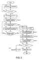
- the control processing executed by the engine control unit 11 in order to determine if the NOx trapping catalytic converter 3 is deteriorated, without using a NOx sensor, will now be explained with reference to the flowchart of Figure 2 .
- the flowchart of Figure 2 indicates the flow of the processing steps over time, but does not indicate a control sequence that is executed repeatedly once per prescribed amount of time.
- Step S1 the engine control unit 11 reads the exhaust gas temperature Tex detected by the temperature sensor 12.
- Step S2 the engine control unit 11 determines if the exhaust gas temperature Tex is in a prescribed temperature region between a lower limit value A and an upper limit value B.
- the prescribed temperature region is an exhaust gas temperature region in which nitrogen dioxide (NO 2 ) discharged from the NOx trapping catalytic converter 3 causes particulate matter captured by the particulate matter filter 4 to be removed by oxidation.
- the prescribed temperature region is set to an exhaust gas temperature region in which a conversion efficiency of the NOx trapping catalytic converter 3 changes greatly when deterioration of the NOx trapping catalytic converter 3 occurs, thus enabling a deterioration determination to be accomplished.
- the reason a temperature region in which the conversion efficiency of the NOx trapping catalytic converter 3 changes greatly is used is to improve the accuracy with which deterioration of the NOx trapping catalytic converter 3 is detected. For example, it is acceptable to set the lower limit value A to approximately 300 C° and the upper limit value B to approximately 450 C°.
- Step S3 the engine control unit 11 proceeds to Step S3 and subsequent steps because it is possible to determine whether or not the NOx trapping catalytic converter 3 is deteriorated.
- the exhaust gas temperature Tex will not enter the prescribed temperature region.
- an intake throttle valve is provided in an intake passage, then the exhaust gas temperature can be adjusted into the prescribed temperature region by closing the intake throttle valve so as to throttle the intake air and by retarding the fuel injection timing of a fuel injection valve 6.
- Steps S3 and S4 the engine control unit 11 detects a particulate accumulation amount S1 of the particulate matter filter 4 at the time when the exhaust gas temperature Tex entered the prescribed temperature.
- the pressure difference across the particulate matter filter 4 depends on the amount of particulate matter accumulated in the particulate matter filter 4.
- the pressure difference across the particulate matter filter 4 increases as the amount of particulate matter accumulated in the particulate matter filter 4 increases.
- Step S3 the engine control unit 11 reads the pressure difference ⁇ P1 of the particulate matter filter 4 detected by the pressure difference sensor 13. Then, in Step S4, the engine control unit 11 detects the particulate accumulation amount S1 of the particulate matter filter 4 at the time when the exhaust gas temperature Tex entered the prescribed temperature in an indirect manner by searching a table of the content expressed in Figure 4 based on the pressure difference ⁇ P1. Since the value S1 will be necessary after a prescribed amount of time (explained later) has elapsed, it is stored in a memory for later use.
- Steps S5 to S7 the engine control unit 11 calculates a summation value of the amount of particulate matter (abbreviated as "PM" in the figures) that flows into the particulate matter filter 4 (i.e., the amount of particulate matter discharged from the engine 1) during a prescribed amount of time starting from the point in time when the condition of Step S2 is satisfied (i.e., the time when the exhaust gas temperature Tex enters the prescribed temperature region).
- PM the amount of particulate matter
- Step S5 the engine control unit 11 estimates the amount of particulate matter flowing into the particulate matter filter 4 each time the engine control unit 11 repeats its control cycle by searching a map of the content shown in Figure 3 based on an operating condition (e.g., engine speed and fuel injection quantity) existing at that time.
- an operating condition e.g., engine speed and fuel injection quantity
- Step S6 the engine control unit 11 estimates a summation value Ve of the amount of particulate matter flowing in during the prescribed amount of time by calculating a summation of the values estimated in Step S5.
- the fuel injection quantity mentioned above is calculated using a control sequence that is not shown in the figures to search a prescribed map based on the engine speed detected by the engine speed sensor 14 and the accelerator position detected by the accelerator sensor 15.
- Step S7 the engine control unit 11 determines if the prescribed amount of time T1 has elapsed since the time when the condition of Step S2 was satisfied. If the prescribed amount of time T1 has not yet elapsed since the time when the condition of Step S2 was satisfied, the engine control unit 11 repeats Steps S5 and S6.
- the amount of particulate matter flowing into the particulate matter filter 4 per control cycle time e.g., 10 ms
- the amount of particulate matter flowing into the particulate matter filter 4 per control cycle time can be calculated by preparing a map of the amount of particulate matter flowing in per control cycle time and searching the prepared map (map shown in Figure 3 ) each time Steps S5 and S6 are repeated (e.g., every 10 ms).
- the summation value Ve of the amount of particulate matter that flowed into the particulate matter filter 4 during the prescribed amount of time T1 (which started when the condition of Step S2 was satisfied) can then be calculated by summing the all of the individual particulate matter inflow amounts per control cycle time calculated for each control cycle.
- an amount of particulate matter corresponding to the summation value Ve (calculated amount of particulate matter captured during the prescribed amount of time) should have been newly captured by the particulate matter filter 4.
- the amount of accumulated particulate matter in the particulate matter filter 4 should be larger than before the prescribed amount of time T1 elapsed.
- an increase amount Vr (actual value) by which the amount of particulate matter accumulated in the particulate matter filter 4 actually increased during the prescribed amount of time will be smaller than the summation value (computed value) described above.
- Step S8 the engine control unit 11 proceeds to Steps S8, S9, and S10 from Step S7 and calculates the increase amount Vr by which the amount of particulate matter accumulated in the particulate matter filter 4 actually increased during the prescribed amount of time T1 after the condition of Step S2 was satisfied.
- Step S8 the engine control unit 11 reads the pressure difference ⁇ P2 across the particulate matter filter 4 detected by the pressure difference sensor 13, and in Step S9 the engine control unit 11 calculates (estimates) the amount S2 of particulate matter accumulated in the particulate matter filter 4 after the prescribed amount of time T1 elapsed by searching a table of the content shown in Figure 4 based on the pressure difference ⁇ P2.
- Step S11 a deterioration determination threshold value C is calculated by searching a table of the content shown in Figure 5 based on the summation value Ve calculated in Step S6 indicating the amount of particulate matter that flowed into the particulate matter filter 4 during the prescribed amount of time T1.
- the amount of particulate matter removed by oxidation with nitrogen dioxide (NO 2 ) changes depending on the summation value Ve of the amount of particulate matter that flowed into the particulate matter filter 4 during the prescribed amount of time.
- the amount of particulate matter removed by oxidation is larger when the summation value Ve of the amount of particulate matter that flowed into the particulate matter filter 4 during the prescribed amount of time is large, than when the summation value Ve is small. Therefore, the deterioration determination threshold value C is set to change according to the summation value Ve of the amount of particulate matter that flows into the particulate matter filter 4 during the prescribed amount of time.
- the increase amount Vr by which the amount of particulate matter accumulated in the particulate matter filter 4 increased during the prescribed amount of time T1 is subtracted from the summation value Ve of the amount of particulate matter that flowed into the particulate matter filter 4 during the prescribed amount of time T1 to obtain a difference ⁇ PM ( Ve - Vr).
- the difference ⁇ PM is dependent on the amount of nitrogen dioxide NO 2 discharged from the NOx trapping catalytic converter 3. The more the NOx trapping catalytic converter 3 degrades, the larger the amount of nitrogen dioxide (NO 2 ) discharged from the NOx trapping catalytic converter 3 becomes and, thus, the difference ⁇ PM increases.
- Step S12 the difference ⁇ PM is compared to the determination threshold value C. If the difference ⁇ PM is larger than the determination threshold value C, then the engine control unit 11 determines that deterioration of the NOx trapping catalytic converter 3 exists and proceeds to Step S13, where it sets the value of a catalyst deterioration flag to 1 (the value of the catalyst deterioration flag being initially set to zero when the engine is started). Conversely, if the difference ⁇ PM is equal to or smaller than the determination threshold value C, then the engine control unit 11 proceeds to Step S14 and sets the catalyst deterioration flag to 0.
- the increase amount Vr by which the amount of particulate matter accumulated in the particulate matter filter 4 increased during the prescribed amount of time is smaller than the summation value Ve (computed value) of the amount of particulate matter that flowed into the particulate matter filter 4 during the prescribed amount of time.
- the apparatus can be configured to determine that the NOx trapping catalytic converter 3 is deteriorated when the difference ⁇ PM is larger than the reference determination value C0.
- Deterioration of the NOx trapping catalytic converter 3 can only be determined accurately using the determination threshold value C0 when the summation value Ve of the amount of particulate matter that flowed into the particulate matter filter 4 during the prescribed amount of time equals the reference summation value D.
- the determination threshold value C0 is not an appropriate value to use.
- the catalyst deterioration determination can be executed accurately when the summation value Ve of the amount of particulate matter that flowed into the particulate matter filter 4 during the prescribed amount of time does not equal the reference summation value D.
- the determination threshold value C is set to a value larger than the reference determination threshold value C0 when the summation value Ve is larger than the reference summation value D. Meanwhile, the determination threshold value C is set to a value smaller than the reference determination threshold value C0 when the summation value Ve is smaller than the reference summation value D.
- the prescribed amount of time T1 is set to an appropriate value.
- the operational effects of this embodiment of the NOx trapping catalytic converter diagnostic apparatus will now be explained.
- the NOx trapping catalytic converter diagnostic apparatus in accordance with this embodiment is used in an exhaust system having the NOx trapping catalytic converter 3 with the particulate matter filter 4 arranged downstream of the NOx trapping catalytic converter 3.
- the NOx trapping catalytic converter diagnostic apparatus calculates a summation value Ve of the amount of particulate matter that flows into the particulate matter filter 4 during a prescribed amount of time (indicating the detected amount of particulate matter that flows into the particulate matter filter) and estimates an increase amount Vr by which the amount of particulate matter accumulated in the particulate matter filter 4 increases during the prescribed amount of time (indicating the estimated amount of particulate matter that accumulates in the particulate matter filter).
- the NOx trapping catalytic converter diagnostic apparatus determines if the NOx trapping catalytic converter 3 is deteriorated using the summation value Ve of the detected amount of particulate matter that flowed into the particulate matter filter 4 during the prescribed amount of time and the increase amount Vr by which the amount of particulate matter accumulated in the particulate matter filter 4 increased during the prescribed amount of time (see Steps S3 to S10 and Steps S12 to S13 of Figure 2 ).
- the NOx trapping catalytic converter diagnostic apparatus can accomplish a deterioration diagnosis of the NOx trapping catalytic converter 3 without employing a NOx sensor.
- the deterioration determining component determines that the NOx trapping catalytic converter 3 is deteriorated if the difference ⁇ PM is larger than a determination threshold value C (see Steps S3 to S10 and Steps S12 to S14 of Figure 2 ).
- a determination threshold value C see Steps S3 to S10 and Steps S12 to S14 of Figure 2 .
- the determination threshold value C is determined in accordance with the summation value Ve of the amount of particulate matter that flows into the particulate matter filter 4 during the prescribed amount of time (see Step S11 of Figure 2 and Figure 5 ).
- the deterioration of the NOx trapping catalytic converter 3 can be detected accurately even if the summation value Ve of the amount of particulate matter that flows into the particulate matter filter 4 during the prescribed amount of time varies due to changes in an operating condition.
- the difference ⁇ PM (between the summation value Ve of the amount of particulate matter that flowed into the particulate matter filter 4 during the prescribed amount of time and the increase amount Vr by which the amount of particulate matter accumulated in the particulate matter filter 4 increased during the prescribed amount of time) does not change when the NOx trapping catalytic converter becomes deteriorated.
- the NOx trapping catalytic converter 3 would be mistakenly diagnosed as not yet deteriorated even if it already was deteriorated. Therefore, in this illustrated embodiment, the summation value Ve of the amount of particulate matter that flows into the particulate matter filter 4 during the prescribed amount of time is calculated and the increase amount Vr by which the amount of particulate matter accumulated in the particulate matter filter 4 increases during the prescribed amount of time is estimated only when the exhaust gas temperature is in a prescribed temperature region in which the conversion efficiency of the NOx trapping catalytic converter 3 changes greatly (markedly) when the NOx trapping catalytic converter 3 becomes deteriorated (i.e., in comparison to before the NOx trapping catalytic converter 3 became deteriorated) and in which a portion of the particulate matter accumulated in the particulate matter filter 4 is removed by oxidation resulting from nitrogen dioxide (NO 2 ) discharged from the NOx trapping catalytic converter 3.
- NO 2 nitrogen dioxide
- the estimation of the particulate matter accumulation estimating component is accomplished by Steps S5 to S7 of Figure 2 and the detection of the particulate matter accumulation detecting component is accomplished by Steps S3, S4, S7, S8, S9, and S10 of Figure 2 .
- the term “comprising” and its derivatives, as used herein, are intended to be open ended terms that specify the presence of the stated features, elements, components, groups, integers, and/or steps, but do not exclude the presence of other unstated features, elements, components, groups, integers and/or steps.
- the foregoing also applies to words having similar meanings such as the terms, “including”, “having” and their derivatives.
- the terms “part,” “section,” “portion,” “member” or “element” when used in the singular can have the dual meaning of a single part or a plurality of parts.
- the term “configured” as used herein to describe a component, section or part of a device includes hardware and/or software that is constructed and/or programmed to carry out the desired function.
Landscapes
- Engineering & Computer Science (AREA)
- Chemical & Material Sciences (AREA)
- Combustion & Propulsion (AREA)
- Chemical Kinetics & Catalysis (AREA)
- Mechanical Engineering (AREA)
- General Engineering & Computer Science (AREA)
- Biomedical Technology (AREA)
- Environmental & Geological Engineering (AREA)
- Analytical Chemistry (AREA)
- General Chemical & Material Sciences (AREA)
- Oil, Petroleum & Natural Gas (AREA)
- Health & Medical Sciences (AREA)
- Exhaust Gas After Treatment (AREA)
- Processes For Solid Components From Exhaust (AREA)
- Exhaust Gas Treatment By Means Of Catalyst (AREA)
Abstract
Description
- The present invention generally relates to a diagnostic apparatus for a NOx trapping catalytic converter and particularly, but not exclusively, to a diagnostic apparatus for a NOx trapping catalytic converter that can determine if a NOx trapping catalytic converter is deteriorated. Aspects of the invention relate to an apparatus, to a method, to an exhaust system and to a vehicle.
- There is a NOx trapping catalytic converter diagnostic technology configured to determine if the catalyst of a NOx trapping catalytic converter is deteriorated based on a signal from a NOx sensor arranged downstream of the NOx trapping catalytic converter. An example of such a NOx trapping catalytic converter diagnostic technology is disclosed in Japanese Laid-Open Patent Publication No.
2000-104536 - It is an aim of the present invention to improve upon such known technology. Embodiments of the invention may provide a NOx trapping catalytic converter diagnostic apparatus that can determine if a NOx trapping catalytic converter is deteriorated. Other aims and advantages of the invention will become apparent from the following description, claims and drawings.
- Aspects of the invention therefore provide an apparatus, a method, an exhaust system and a vehicle as claimed in the appended claims.
- According to another aspect of the invention for which protection is sought there is provided a NOx trapping catalytic converter diagnostic apparatus comprising a particulate matter accumulation estimating component configured to estimate an estimated amount of particulate matter accumulated in a particulate matter filter that is positioned downstream of a NOx trapping catalytic converter based on at least the particulate matter flowing into the particulate matter filter, a particulate matter accumulation detecting component configured to detect a detected amount of particulate matter accumulated in the particulate matter filter and a deterioration determining component configured to determine if deterioration of the NOx trapping catalytic converter has occurred based on the estimated amount of accumulated particulate matter and the detected amount of accumulated particulate matter.
- In an embodiment, the particulate matter accumulation estimating component is further configured to estimate the estimated amount of particulate matter that flows into the particulate matter filter during a prescribed amount of time based on an engine operating condition and the particulate matter accumulation detecting component is further configured to detect the detected amount of particulate matter that accumulates in the particulate matter filter during the prescribed amount of time based on a detected pressure difference across the particulate matter filter.
- In an embodiment, the deterioration determining component is further configured to determine that deterioration of the NOx trapping catalytic converter has occurred when a difference between the estimated amount of particulate matter estimated for the prescribed amount of time and the detected amount of particulate matter detected for the prescribed amount of time is larger than a determination threshold value.
- In an embodiment, the deterioration determining component is further configured to set the determination threshold value based on an amount of particulate matter that flows in for the prescribed amount of time.
- In an embodiment, the particulate matter accumulation estimating component is further configured to estimate the estimated amount of particulate matter that flows into the particulate matter filter for the prescribed amount of time when an exhaust gas temperature is in a prescribed temperature region, and the particulate matter accumulation detecting component is further configured to detect an increase amount by which the detected amount of accumulated particulate matter increases for the prescribed amount of time when the exhaust gas temperature is in the prescribed temperature region.
- In an embodiment, the particulate matter accumulation detecting component is further configured to set the prescribed temperature region as an exhaust gas temperature region in which a conversion efficiency of the NOx trapping catalytic converter changes when deterioration of the NOx trapping catalytic converter occurs and in which nitrogen dioxide flowing out of the NOx trapping catalytic converter causes particulate matter accumulated in the particulate matter filter to be removed by oxidation.
- In an embodiment, the particulate matter accumulation detecting component is further configured to set the prescribed temperature region as a region from about 250 C° to about 450 C°.
- In an embodiment, the particulate matter accumulation estimating component is further configured to estimate the estimated amount of particulate matter that flows into the particulate matter filter for the prescribed amount of time based on a fuel injection quantity and an engine rotational speed.
- According to a further aspect of the invention for which protection is sought there is provided a method of determining deterioration of a NOx trapping catalytic converter comprising estimating an estimated amount of particulate matter accumulated in a particulate matter filter that is positioned downstream of the NOx trapping catalytic converter based on at least the particulate matter flowing into the particulate matter filter, detecting a detected amount of particulate matter accumulated in the particulate matter filter and determining deterioration of the NOx trapping catalytic converter based on the estimated amount of accumulated particulate matter and the detected amount of accumulated particulate matter.
- In an embodiment, the estimating of the estimated amount of particulate matter is conducted based on an engine operating condition occurring during a prescribed amount of time and the detecting of the detected amount of particulate matter that accumulates in the particulate matter filter is conducted based on a detected pressure difference across the particulate matter filter during the prescribed amount of time.
- In an embodiment, the determining of the deterioration of the NOx trapping catalytic converter includes determining deterioration has occurred when a difference between the estimated and detected amounts for the prescribed amount of time is larger than a determination threshold value.
- In an embodiment, the determining of the deterioration of the NOx trapping catalytic converter includes setting the determination threshold value based on an amount of particulate matter that flows in for the prescribed amount of time.
- In an embodiment, the estimating of the estimated amount of particulate matter for the prescribed amount of time is executed when an exhaust gas temperature is in a prescribed temperature region, and the detecting of the detected amount of accumulated particulate matter includes detecting an increase amount by which the detected amount of accumulated particulate matter increases for the prescribed amount of time, which is executed when the exhaust gas temperature is in the prescribed temperature region.
- In an embodiment, the detecting of the detected amount of accumulated particulate matter includes setting the prescribed temperature region as an exhaust gas temperature region in which a conversion efficiency of the NOx trapping catalytic converter changes when deterioration of the NOx trapping catalytic converter occurs and in which nitrogen dioxide flowing out of the NOx trapping catalytic converter causes particulate matter accumulated in the particulate matter filter to be removed by oxidation.
- In an embodiment, the detecting of the detected amount of accumulated particulate matter includes setting the prescribed temperature region as a region from about 250 C° to about 450 C°.
- In an embodiment, the estimating of the estimated amount of particulate matter for the prescribed amount of time is based on a fuel injection quantity and an engine rotational speed.
- According to a still further aspect of the invention for which protection is sought there is provided a NOx trapping catalytic converter diagnostic apparatus comprising a NOx trapping catalytic converter arranged in an exhaust passage of an engine, a particulate matter filter arranged downstream of the NOx trapping catalytic converter and a controller for controlling an operational state of the engine, the controller further comprising particulate matter accumulation estimating means for estimating an estimated amount of particulate matter accumulated in the particulate matter filter based on the operational state of the engine, particulate matter accumulation detecting means for detecting a detected amount of particulate matter accumulated in the particulate matter filter and deterioration determining means for determining if deterioration of the NOx trapping catalytic converter has occurred based on the estimated amount of accumulated particulate matter and the detected amount of accumulated particulate matter.
- For example, in embodiments of the invention a NOx trapping catalytic converter diagnostic apparatus may comprise a particulate matter accumulation estimating component, a particulate matter accumulation detecting component and a deterioration determining component. The particulate matter accumulation estimating component is configured to estimate an estimated amount of the particulate matter accumulated a particulate matter filter that is positioned downstream of a NOx trapping catalytic converter. The particulate matter accumulation detecting component is configured to detect a detected amount of particulate matter accumulated in the particulate matter filter. The deterioration determining component is configured to determine if deterioration of the NOx trapping catalytic converter has occurred based on the estimated amount of accumulated particulate matter and the detected amount of accumulated particulate matter.
- Within the scope of this application it is envisaged that the various aspects, embodiments, examples, features and alternatives set out in the preceding paragraphs, in the claims and/or in the following description and drawings may be taken individually or in any combination thereof.
- The present invention will now be described, by way of example only, with reference to the accompanying drawings in which:
-
Figure 1 is a schematic block diagram of an internal combustion engine (e.g., a diesel engine) with an exhaust gas cleaning apparatus including a NOx trapping catalytic converter diagnostic apparatus in accordance with a first embodiment; -
Figure 2 is a flowchart of the control routine executed by the control unit to determine if the NOx trapping catalytic converter has deteriorated; -
Figure 3 is a characteristic diagram plotting the amount of particulate matter that flows into the particulate matter filter per control cycle; -
Figure 4 is a characteristic diagram plotting the amount of particulate matter that accumulates in the particulate matter filter; and -
Figure 5 is a characteristic diagram plotting a determination threshold value. - Selected embodiments of the present invention will now be explained with reference to the drawings. It will be apparent to those skilled in the art from this disclosure that the following descriptions of the embodiments of the present invention are provided for illustration only and not for the purpose of limiting the invention as defined by the appended claims and their equivalents.
- Referring initially to
Figure 1 , an internal combustion engine 1 (e.g., a diesel engine) is illustrated with an exhaust gas cleaning apparatus including a NOx trapping catalytic converter diagnostic apparatus in accordance with a first embodiment. Thediesel engine 1 shown inFigure 1 is configured to operate in a region where the excess air ratio is larger than 1, i.e., with an air fuel mixture containing excess air. Consequently, a large amount of NOx is contained in the exhaust gas. When the engine load increases, the fuel injection quantity increases and the air utilization rate worsens, causing particulate matter to be contained in the exhaust gas. Thediesel engine 1 of this type is well known in the art. Since diesel engines of this type are well known in the art, the precise structure of thediesel engine 1 will not be discussed or illustrated in detail herein. - The
diesel engine 1 hasexhaust gas passage 2 to expel the exhaust gas from the combustion chamber of thediesel engine 1. In order to clean the NOx and the particulate matter from the exhaust gas, a three-way trappingcatalytic converter 3 having a NOx trapping function (hereinafter called "NOx trapping catalytic converter") and a particulate matter filter 4 are arranged in theexhaust gas passage 2. The NOx trappingcatalytic converter 3 is arranged upstream of the particulate matter filter 4. The NOx trapping catalytic converter is configured to adsorb and store NOx contained in the exhaust gas when an air fuel ratio of the exhaust gas is leaner than a stoichiometric air fuel ratio and to release the stored NOx with a reduction reaction when the air fuel ratio of the exhaust gas is richer than the stoichiometric air fuel ratio. When the stored NOx is released, it is cleaned in a reduction reaction by using HC and CO as reduction agents. HC and CO exist in large quantities in the exhaust gas. The three-way catalyst functions to accomplish this reduction cleaning of the NOx. - The particulate matter filter 4 serves to capture particulate matter contained in the exhaust gas and has, for example, a honeycomb wall structure. In such a filter, many generally parallel flow passages are provided with the inlets of alternating flow passages being blocked, and with the outlets of the flow passages whose inlets are open (not blocked) being blocked. The passages are separated by filter walls and the particulate matter filter 4 is configured such that the exhaust gas must pass through the particulate matter filter walls. Since the particulate matter born by the exhaust gas cannot pass through the particulate matter filter walls, it is captured by the membranes of the particulate matter filter 4.
- Thus, in this illustrated embodiment, the NOx trapping
catalytic converter 3 and the particulate matter filter 4 are arranged in theexhaust passage 2 to form an engine exhaust gas cleaning apparatus. The exhaust gas cleaning apparatus further includes anengine control unit 11, an exhaustgas temperature sensor 12, apressure difference sensor 13, anengine speed sensor 14 and anaccelerator sensor 15 such that exhaust gas cleaning apparatus further includes a NOx trapping catalytic converter diagnostic apparatus. The NOx trapping catalytic converter diagnostic apparatus determines if the NOx trappingcatalytic converter 3 has deteriorated without the need to provide a NOx sensor. - The principles on which the deterioration determination of the NOx trapping
catalytic converter 3 is based will now be explained. The NOx discharged from theengine 1 is oxidized into nitrogen dioxide (NO2) by the NOx trappingcatalytic converter 3 and the nitrogen dioxide (NO2) is stored in the NOx trappingcatalytic converter 3. As the deterioration of the NOx trappingcatalytic converter 3 progresses, the amount of nitrogen dioxide (NO2) stored in the catalyst decreases and the amount of nitrogen dioxide (NO2) discharged from the NOx trappingcatalytic converter 3 increases. Meanwhile, when the exhaust gas temperature is approximately 450 C°, a portion of the particulate matter captured in the particulate matter filter 4 positioned downstream of the NOx trappingcatalytic converter 3 is removed by oxidization in which the nitrogen dioxide (NO2) contained in the exhaust gas flowing from upstream functions as an oxidizing agent. If the amount of nitrogen dioxide (NO2) flowing into the particulate matter filter 4 (i.e., the amount of nitrogen dioxide flowing out of the NOx trapping catalytic converter 3) increases, then the amount of particulate matter removed from the particulate matter filter 4 by oxidation will increase. In short, the larger the amount of particulate matter removed from the particulate matter filter 4 by oxidation is, the larger the amount of nitrogen dioxide (NO2) discharged from the NOx trappingcatalytic converter 3 can be determined to be. - Thus, when the amount of particulate matter removed from the particulate matter filter 4 by oxidation exceeds a prescribed value (determination threshold value), it can be determined that the NOx trapping
catalytic converter 3 is deteriorated. The NOx trapping catalytic converter diagnostic apparatus determines if the NOx trappingcatalytic converter 3 is deteriorated based on the amount of particulate matter flowing into the particulate matter filter 4 and the amount of particulate matter accumulating in the particulate matter filter 4, i.e., based on a summation value (estimate value) of the amount of particulate matter entering the particulate matter filter 4 per prescribed amount of time and an increase (detection value) in the amount of particulate matter accumulating in the particulate matter filter 4 per the same prescribed amount of time. - Thus, the determination as to whether or not the NOx trapping
catalytic converter 3 is deteriorated is accomplished by theengine control unit 11 based on the following signals fed to theengine control unit 11 bysensors 12 to 15. Theengine control unit 11 receives an exhaust gas temperature signal from the exhaustgas temperature sensor 12, which is provided upstream of the particulate matter filter 4. Theengine control unit 11 receives pressure difference signal from thepressure difference sensor 13, which is configured to measure a pressure difference across the particulate matter filter 4. Theengine control unit 11 receives a rotational speed signal from theengine speed sensor 14. Theengine control unit 11 receives an accelerator position signal from theaccelerator sensor 15. - Basically, the NOx trapping catalytic converter diagnostic apparatus of the illustrated embodiment accomplishes the determination as to whether or not the NOx trapping catalytic converter has deteriorated based on a calculation of the amount of particulate matter that flows into the particulate matter filter 4 and an estimate of the amount of particulate matter that has accumulated in the particulate matter filter 4. Thus, the NOx trapping catalytic converter diagnostic apparatus can diagnose whether or not the NOx trapping catalytic converter is deteriorated without using a NOx sensor in the determination.
- The control processing executed by the
engine control unit 11 in order to determine if the NOx trappingcatalytic converter 3 is deteriorated, without using a NOx sensor, will now be explained with reference to the flowchart ofFigure 2 . The flowchart ofFigure 2 indicates the flow of the processing steps over time, but does not indicate a control sequence that is executed repeatedly once per prescribed amount of time. - In Step S1 the
engine control unit 11 reads the exhaust gas temperature Tex detected by thetemperature sensor 12. In Step S2, theengine control unit 11 determines if the exhaust gas temperature Tex is in a prescribed temperature region between a lower limit value A and an upper limit value B. The prescribed temperature region is an exhaust gas temperature region in which nitrogen dioxide (NO2) discharged from the NOx trappingcatalytic converter 3 causes particulate matter captured by the particulate matter filter 4 to be removed by oxidation. Additionally, the prescribed temperature region is set to an exhaust gas temperature region in which a conversion efficiency of the NOx trappingcatalytic converter 3 changes greatly when deterioration of the NOx trappingcatalytic converter 3 occurs, thus enabling a deterioration determination to be accomplished. The reason a temperature region in which the conversion efficiency of the NOx trappingcatalytic converter 3 changes greatly is used is to improve the accuracy with which deterioration of the NOx trappingcatalytic converter 3 is detected. For example, it is acceptable to set the lower limit value A to approximately 300 C° and the upper limit value B to approximately 450 C°. - If the exhaust gas temperature Tex is not in the prescribed temperature region (A ≤ Tex ≤ B), then the
engine control unit 11 returns to Steps S1 and S2 and waits until the condition A ≤ Tex ≤ B is satisfied. When the exhaust gas temperature Tex enters the prescribed temperature region, theengine control unit 11 proceeds to Step S3 and subsequent steps because it is possible to determine whether or not the NOx trappingcatalytic converter 3 is deteriorated. - Depending on the operating conditions, it is possible that the exhaust gas temperature Tex will not enter the prescribed temperature region. In such a case, if an intake throttle valve is provided in an intake passage, then the exhaust gas temperature can be adjusted into the prescribed temperature region by closing the intake throttle valve so as to throttle the intake air and by retarding the fuel injection timing of a fuel injection valve 6.
- In this embodiment, a case is considered in which the exhaust gas temperature Tex is not initially in the prescribed temperature region (A ≤ Tex ≤ B) but then enters the prescribed temperature region due to a change in operating conditions and remains in the prescribed temperature region for a while (a time longer than a prescribed amount of time T1 explained later).
- In Steps S3 and S4, the
engine control unit 11 detects a particulate accumulation amount S1 of the particulate matter filter 4 at the time when the exhaust gas temperature Tex entered the prescribed temperature. The pressure difference across the particulate matter filter 4 depends on the amount of particulate matter accumulated in the particulate matter filter 4. The pressure difference across the particulate matter filter 4 increases as the amount of particulate matter accumulated in the particulate matter filter 4 increases. - In Step S3, the
engine control unit 11 reads the pressure difference ΔP1 of the particulate matter filter 4 detected by thepressure difference sensor 13. Then, in Step S4, theengine control unit 11 detects the particulate accumulation amount S1 of the particulate matter filter 4 at the time when the exhaust gas temperature Tex entered the prescribed temperature in an indirect manner by searching a table of the content expressed inFigure 4 based on the pressure difference ΔP1. Since the value S1 will be necessary after a prescribed amount of time (explained later) has elapsed, it is stored in a memory for later use. - In Steps S5 to S7, the
engine control unit 11 calculates a summation value of the amount of particulate matter (abbreviated as "PM" in the figures) that flows into the particulate matter filter 4 (i.e., the amount of particulate matter discharged from the engine 1) during a prescribed amount of time starting from the point in time when the condition of Step S2 is satisfied (i.e., the time when the exhaust gas temperature Tex enters the prescribed temperature region). - More specifically, in Step S5, the
engine control unit 11 estimates the amount of particulate matter flowing into the particulate matter filter 4 each time theengine control unit 11 repeats its control cycle by searching a map of the content shown inFigure 3 based on an operating condition (e.g., engine speed and fuel injection quantity) existing at that time. - In Step S6, the
engine control unit 11 estimates a summation value Ve of the amount of particulate matter flowing in during the prescribed amount of time by calculating a summation of the values estimated in Step S5. The fuel injection quantity mentioned above is calculated using a control sequence that is not shown in the figures to search a prescribed map based on the engine speed detected by theengine speed sensor 14 and the accelerator position detected by theaccelerator sensor 15. - In Step S7, the
engine control unit 11 determines if the prescribed amount of time T1 has elapsed since the time when the condition of Step S2 was satisfied. If the prescribed amount of time T1 has not yet elapsed since the time when the condition of Step S2 was satisfied, theengine control unit 11 repeats Steps S5 and S6. The amount of particulate matter flowing into the particulate matter filter 4 per control cycle time (e.g., 10 ms) can be calculated by preparing a map of the amount of particulate matter flowing in per control cycle time and searching the prepared map (map shown inFigure 3 ) each time Steps S5 and S6 are repeated (e.g., every 10 ms). The summation value Ve of the amount of particulate matter that flowed into the particulate matter filter 4 during the prescribed amount of time T1 (which started when the condition of Step S2 was satisfied) can then be calculated by summing the all of the individual particulate matter inflow amounts per control cycle time calculated for each control cycle. - When the prescribed amount of time T1 has elapsed since the condition of Step S2 was satisfied, an amount of particulate matter corresponding to the summation value Ve (calculated amount of particulate matter captured during the prescribed amount of time) should have been newly captured by the particulate matter filter 4. Thus, the amount of accumulated particulate matter in the particulate matter filter 4 should be larger than before the prescribed amount of time T1 elapsed. However, if a portion of the particulate matter accumulated in the particulate matter filter 4 is removed by oxidation resulting from nitrogen dioxide (NO2) discharged from the NOx trapping
catalytic converter 3, then an increase amount Vr (actual value) by which the amount of particulate matter accumulated in the particulate matter filter 4 actually increased during the prescribed amount of time will be smaller than the summation value (computed value) described above. - Therefore, after the prescribed amount of time T1 has elapsed since the condition of Step S2 is satisfied, the
engine control unit 11 proceeds to Steps S8, S9, and S10 from Step S7 and calculates the increase amount Vr by which the amount of particulate matter accumulated in the particulate matter filter 4 actually increased during the prescribed amount of time T1 after the condition of Step S2 was satisfied. More specifically, in Step S8 theengine control unit 11 reads the pressure difference ΔP2 across the particulate matter filter 4 detected by thepressure difference sensor 13, and in Step S9 theengine control unit 11 calculates (estimates) the amount S2 of particulate matter accumulated in the particulate matter filter 4 after the prescribed amount of time T1 elapsed by searching a table of the content shown inFigure 4 based on the pressure difference ΔP2. Then, by subtracting the particulate matter accumulation amount S1 (amount of particulate matter accumulated before the prescribed amount of time elapsed) from the particulate matter accumulation amount S2 (amount of particulate matter accumulated after the prescribed amount of time elapsed), theengine control unit 11 calculates (estimates) the increase amount Vr (= S2 - S1) by which the amount of particulate matter accumulated in the particulate matter filter 4 increased during the prescribed amount of time T1. - In Step S11, a deterioration determination threshold value C is calculated by searching a table of the content shown in
Figure 5 based on the summation value Ve calculated in Step S6 indicating the amount of particulate matter that flowed into the particulate matter filter 4 during the prescribed amount of time T1. The amount of particulate matter removed by oxidation with nitrogen dioxide (NO2) changes depending on the summation value Ve of the amount of particulate matter that flowed into the particulate matter filter 4 during the prescribed amount of time. In other words, the amount of particulate matter removed by oxidation is larger when the summation value Ve of the amount of particulate matter that flowed into the particulate matter filter 4 during the prescribed amount of time is large, than when the summation value Ve is small. Therefore, the deterioration determination threshold value C is set to change according to the summation value Ve of the amount of particulate matter that flows into the particulate matter filter 4 during the prescribed amount of time. - The increase amount Vr by which the amount of particulate matter accumulated in the particulate matter filter 4 increased during the prescribed amount of time T1 is subtracted from the summation value Ve of the amount of particulate matter that flowed into the particulate matter filter 4 during the prescribed amount of time T1 to obtain a difference ΔPM (= Ve - Vr). The difference ΔPM is dependent on the amount of nitrogen dioxide NO2 discharged from the NOx trapping
catalytic converter 3. The more the NOx trappingcatalytic converter 3 degrades, the larger the amount of nitrogen dioxide (NO2) discharged from the NOx trappingcatalytic converter 3 becomes and, thus, the difference ΔPM increases. By comparing the difference ΔPM to the determination threshold value C, the NOx trappingcatalytic converter 3 can be determined not to be deteriorated if the difference ΔPM is equal to or smaller than the determination threshold value C and to be deteriorated if the difference ΔPM is larger than the determination threshold value C. Therefore, in Step S12, the difference ΔPM is compared to the determination threshold value C. If the difference ΔPM is larger than the determination threshold value C, then theengine control unit 11 determines that deterioration of the NOx trappingcatalytic converter 3 exists and proceeds to Step S13, where it sets the value of a catalyst deterioration flag to 1 (the value of the catalyst deterioration flag being initially set to zero when the engine is started). Conversely, if the difference ΔPM is equal to or smaller than the determination threshold value C, then theengine control unit 11 proceeds to Step S14 and sets the catalyst deterioration flag to 0. - When the flowchart of
Figure 2 is executed while the NOx trappingcatalytic converter 3 is new and the summation value Ve of the amount of particulate matter that has flowed into the particulate matter filter 4 is found to be at a reference summation value D when the condition of Step S2 is satisfied, the difference ΔPM will be at a prescribed value Cini that is not zero. This occurs because even when the NOx trappingcatalytic converter 3 is new, a small amount of nitrogen dioxide (NO2) is discharged from the NOx trappingcatalytic converter 3 and this discharged nitrogen dioxide causes a portion of the particulate matter accumulated in the particulate matter filter 4 to be oxidized. Consequently, the increase amount Vr by which the amount of particulate matter accumulated in the particulate matter filter 4 increased during the prescribed amount of time is smaller than the summation value Ve (computed value) of the amount of particulate matter that flowed into the particulate matter filter 4 during the prescribed amount of time. Thus, by establishing a reference determination threshold value C0 calculated by adding a tolerance value ε to the prescribed value Cini, the apparatus can be configured to determine that the NOx trappingcatalytic converter 3 is deteriorated when the difference ΔPM is larger than the reference determination value C0. - Deterioration of the NOx trapping
catalytic converter 3 can only be determined accurately using the determination threshold value C0 when the summation value Ve of the amount of particulate matter that flowed into the particulate matter filter 4 during the prescribed amount of time equals the reference summation value D. When the summation value Ve does not equal the reference summation value D due to a difference in the operating conditions, the determination threshold value C0 is not an appropriate value to use. However, by usingFigure 5 , the catalyst deterioration determination can be executed accurately when the summation value Ve of the amount of particulate matter that flowed into the particulate matter filter 4 during the prescribed amount of time does not equal the reference summation value D. Thus, as indicated inFigure 5 , the determination threshold value C is set to a value larger than the reference determination threshold value C0 when the summation value Ve is larger than the reference summation value D. Meanwhile, the determination threshold value C is set to a value smaller than the reference determination threshold value C0 when the summation value Ve is smaller than the reference summation value D. - When the prescribed amount of time T1 is longer, the accuracy of the catalyst deterioration diagnosis is better but the opportunities to execute a catalyst deterioration diagnosis are fewer. Conversely, when the prescribed amount of time T1 is shorter, the number of opportunities to execute a catalyst deterioration diagnosis is larger but the accuracy of the catalyst deterioration diagnosis executed is lower. Therefore, the prescribed amount of time T1 is set to an appropriate value.
- The operational effects of this embodiment of the NOx trapping catalytic converter diagnostic apparatus will now be explained. The NOx trapping catalytic converter diagnostic apparatus in accordance with this embodiment is used in an exhaust system having the NOx trapping
catalytic converter 3 with the particulate matter filter 4 arranged downstream of the NOx trappingcatalytic converter 3. The NOx trapping catalytic converter diagnostic apparatus calculates a summation value Ve of the amount of particulate matter that flows into the particulate matter filter 4 during a prescribed amount of time (indicating the detected amount of particulate matter that flows into the particulate matter filter) and estimates an increase amount Vr by which the amount of particulate matter accumulated in the particulate matter filter 4 increases during the prescribed amount of time (indicating the estimated amount of particulate matter that accumulates in the particulate matter filter). The NOx trapping catalytic converter diagnostic apparatus then determines if the NOx trappingcatalytic converter 3 is deteriorated using the summation value Ve of the detected amount of particulate matter that flowed into the particulate matter filter 4 during the prescribed amount of time and the increase amount Vr by which the amount of particulate matter accumulated in the particulate matter filter 4 increased during the prescribed amount of time (see Steps S3 to S10 and Steps S12 to S13 ofFigure 2 ). As a result, the NOx trapping catalytic converter diagnostic apparatus can accomplish a deterioration diagnosis of the NOx trappingcatalytic converter 3 without employing a NOx sensor. - In the NOx trapping catalytic converter diagnostic apparatus in accordance with the illustrated embodiment, the deterioration determining component calculates a difference ΔPM between the summation value Ve of the amount of particulate matter that flowed into the particulate matter filter 4 during the prescribed amount of time and the increase amount Vr by which the amount of particulate matter accumulated in the particulate matter filter 4 increased during the prescribed amount of time (ΔPM = Ve - Vr). The deterioration determining component then determines that the NOx trapping
catalytic converter 3 is deteriorated if the difference ΔPM is larger than a determination threshold value C (see Steps S3 to S10 and Steps S12 to S14 ofFigure 2 ). As a result, deterioration of the NOx trappingcatalytic converter 3 can be detected accurately even if the summation value Ve of the amount of particulate matter that flows into the particulate matter filter 4 during the prescribed amount of time varies. - In the illustrated embodiment, the determination threshold value C is determined in accordance with the summation value Ve of the amount of particulate matter that flows into the particulate matter filter 4 during the prescribed amount of time (see Step S11 of
Figure 2 andFigure 5 ). As a result, the deterioration of the NOx trappingcatalytic converter 3 can be detected accurately even if the summation value Ve of the amount of particulate matter that flows into the particulate matter filter 4 during the prescribed amount of time varies due to changes in an operating condition. - In an exhaust gas temperature region where the conversion efficiency of the NOx trapping
catalytic converter 3 substantially does not change when the NOx trapping catalytic converter becomes deteriorated and in an exhaust gas temperature region where the nitrogen dioxide (NO2) discharged from the NOx trappingcatalytic converter 3 does not cause particulate matter accumulated in the particulate matter filter 4 to be removed by oxidation, the difference ΔPM (between the summation value Ve of the amount of particulate matter that flowed into the particulate matter filter 4 during the prescribed amount of time and the increase amount Vr by which the amount of particulate matter accumulated in the particulate matter filter 4 increased during the prescribed amount of time) does not change when the NOx trapping catalytic converter becomes deteriorated. Thus, in these temperature regions, the NOx trappingcatalytic converter 3 would be mistakenly diagnosed as not yet deteriorated even if it already was deteriorated. Therefore, in this illustrated embodiment, the summation value Ve of the amount of particulate matter that flows into the particulate matter filter 4 during the prescribed amount of time is calculated and the increase amount Vr by which the amount of particulate matter accumulated in the particulate matter filter 4 increases during the prescribed amount of time is estimated only when the exhaust gas temperature is in a prescribed temperature region in which the conversion efficiency of the NOx trappingcatalytic converter 3 changes greatly (markedly) when the NOx trappingcatalytic converter 3 becomes deteriorated (i.e., in comparison to before the NOx trappingcatalytic converter 3 became deteriorated) and in which a portion of the particulate matter accumulated in the particulate matter filter 4 is removed by oxidation resulting from nitrogen dioxide (NO2) discharged from the NOx trappingcatalytic converter 3. As a result, deterioration of the trapping catalytic converter can be determined accurately. - The estimation of the particulate matter accumulation estimating component is accomplished by Steps S5 to S7 of
Figure 2 and the detection of the particulate matter accumulation detecting component is accomplished by Steps S3, S4, S7, S8, S9, and S10 ofFigure 2 . - In understanding the scope of the present invention, the term "comprising" and its derivatives, as used herein, are intended to be open ended terms that specify the presence of the stated features, elements, components, groups, integers, and/or steps, but do not exclude the presence of other unstated features, elements, components, groups, integers and/or steps. The foregoing also applies to words having similar meanings such as the terms, "including", "having" and their derivatives. Also, the terms "part," "section," "portion," "member" or "element" when used in the singular can have the dual meaning of a single part or a plurality of parts. The term "configured" as used herein to describe a component, section or part of a device includes hardware and/or software that is constructed and/or programmed to carry out the desired function.
- While only selected embodiments have been chosen to illustrate the present invention, it will be apparent to those skilled in the art from this disclosure that various changes and modifications can be made herein without departing from the scope of the invention as defined in the appended claims. For example, the size, shape, location or orientation of the various components can be changed as needed and/or desired. Components that are shown directly connected or contacting each other can have intermediate structures disposed between them. The functions of one element can be performed by two, and vice versa. The structures and functions of one embodiment can be adopted in another embodiment. It is not necessary for all advantages to be present in a particular embodiment at the same time. Every feature which is unique from the prior art, alone or in combination with other features, also should be considered a separate description of further inventions by the applicant, including the structural and/or functional concepts embodied by such feature(s). Thus, the foregoing descriptions of the embodiments according to the present invention are provided for illustration only, and not for the purpose of limiting the invention as defined by the appended claims and their equivalents.
- This application claims priority from Japanese Patent Application No.
2007-070400, filed 19th March 2007
Claims (10)
- An apparatus for use with a NOx trapping catalytic converter, the apparatus comprising:particulate matter accumulation estimation means for estimating an amount of particulate matter accumulated in a particulate matter filter that is positioned downstream of a NOx trapping catalytic converter based on at least the particulate matter flowing into the particulate matter filter;particulate matter accumulation detection means for detecting an amount of particulate matter accumulated in the particulate matter filter; anddeterioration determination means for determining if deterioration of the NOx trapping catalytic converter has occurred based on the estimated amount of accumulated particulate matter and the detected amount of accumulated particulate matter.
- An apparatus as claimed in claim 1, whereinthe particulate matter accumulation estimation means is arranged to estimate the amount of particulate matter that flows into the particulate matter filter during a prescribed amount of time based on an engine operating condition; andthe particulate matter accumulation detection means is arranged to detect the amount of particulate matter that accumulates in the particulate matter filter during the prescribed amount of time based on a detected pressure difference across the particulate matter filter.
- An apparatus as claimed in claim 2, wherein the deterioration determination means is arranged to determine that deterioration of the NOx trapping catalytic converter has occurred when a difference between the estimated amount of particulate matter estimated for the prescribed amount of time and the detected amount of particulate matter detected for the prescribed amount of time is larger than a determination threshold value.
- An apparatus as claimed in claim 3, wherein the deterioration determination means is arranged to set the determination threshold value based on an amount of particulate matter that flows in for the prescribed amount of time.
- An apparatus as claimed in any of claims 2 to 4, whereinthe particulate matter accumulation estimation means is arranged to estimate the estimated amount of particulate matter that flows into the particulate matter filter for the prescribed amount of time when an exhaust gas temperature is in a prescribed temperature region; andthe particulate matter accumulation detection means is arranged to detect an increase amount by which the detected amount of accumulated particulate matter increases for the prescribed amount of time when the exhaust gas temperature is in the prescribed temperature region.
- An apparatus as claimed in any claim 5, wherein the particulate matter accumulation detection means is arranged to set the prescribed temperature region as an exhaust gas temperature region in which a conversion efficiency of the NOx trapping catalytic converter changes when deterioration of the NOx trapping catalytic converter occurs and in which nitrogen dioxide flowing out of the NOx trapping catalytic converter causes particulate matter accumulated in the particulate matter filter to be removed by oxidation.
- An apparatus as claimed in claim 5 or claim 6, wherein the particulate matter accumulation detection means is arranged to set the prescribed temperature region as a region from about 250 C° to about 450 C°.
- An apparatus as claimed in any of claims 2 to 7, wherein the particulate matter accumulation estimation means is arranged to estimate the estimated amount of particulate matter that flows into the particulate matter filter for the prescribed amount of time based on a fuel injection quantity and an engine rotational speed.
- A method comprising:estimating an amount of particulate matter accumulated in a particulate matter filter that is positioned downstream of a NOx trapping catalytic converter based on at least the particulate matter flowing into the particulate matter filter;detecting an amount of particulate matter accumulated in the particulate matter filter; anddetermining deterioration of the NOx trapping catalytic converter based on the estimated amount of accumulated particulate matter and the detected amount of accumulated particulate matter.
- A NOx trapping catalytic converter diagnostic apparatus comprising:a NOx trapping catalytic converter arranged in an exhaust passage of an engine;a particulate matter filter arranged downstream of the NOx trapping catalytic converter; andcontrol means for controlling an operational state of the engine, the control means comprising:particulate matter accumulation estimating means for estimating an estimated amount of particulate matter accumulated in the particulate matter filter based on the operational state of the engine;particulate matter accumulation detecting means for detecting a detected amount of particulate matter accumulated in the particulate matter filter; anddeterioration determining means for determining if deterioration of the NOx trapping catalytic converter has occurred based on the estimated amount of accumulated particulate matter and the detected amount of accumulated particulate matter.
Applications Claiming Priority (1)
| Application Number | Priority Date | Filing Date | Title |
|---|---|---|---|
| JP2007070400A JP4349425B2 (en) | 2007-03-19 | 2007-03-19 | NOx catalyst diagnostic device |
Publications (2)
| Publication Number | Publication Date |
|---|---|
| EP1985830A1 true EP1985830A1 (en) | 2008-10-29 |
| EP1985830B1 EP1985830B1 (en) | 2010-06-16 |
Family
ID=39620183
Family Applications (1)
| Application Number | Title | Priority Date | Filing Date |
|---|---|---|---|
| EP08152828A Expired - Fee Related EP1985830B1 (en) | 2007-03-19 | 2008-03-17 | NOx trapping catalytic converter diagnostis |
Country Status (4)
| Country | Link |
|---|---|
| US (1) | US8146346B2 (en) |
| EP (1) | EP1985830B1 (en) |
| JP (1) | JP4349425B2 (en) |
| DE (1) | DE602008001525D1 (en) |
Cited By (2)
| Publication number | Priority date | Publication date | Assignee | Title |
|---|---|---|---|---|
| WO2011107686A1 (en) | 2010-03-02 | 2011-09-09 | Peugeot Citroën Automobiles SA | Method for detecting the defective operation of a particulate filter of a pollution control system |
| EP2930323A4 (en) * | 2012-12-07 | 2016-02-17 | Toyota Motor Co Ltd | DEVICE FOR DETECTING ANOMALY IN AN EXHAUST GAS PURIFIER |
Families Citing this family (20)
| Publication number | Priority date | Publication date | Assignee | Title |
|---|---|---|---|---|
| WO2006101987A2 (en) * | 2005-03-17 | 2006-09-28 | Southwest Research Institute | Use of recirculated exhaust gas in a burner-based exhaust generation system for reduced fuel consumption and for cooling |
| US20110120090A1 (en) * | 2009-11-25 | 2011-05-26 | Sorensen Jr Charles Mitchel | Processes And Devices For Regenerating Gasoline Particulate Filters |
| DE102011002937A1 (en) * | 2011-01-20 | 2012-07-26 | Ford Global Technologies, Llc | Particle sensor, exhaust system and method for determining particles in the exhaust gas |
| WO2015093603A1 (en) | 2013-12-19 | 2015-06-25 | トヨタ自動車株式会社 | Exhaust gas purification system for internal combustion engine |
| US10233811B2 (en) * | 2017-03-27 | 2019-03-19 | GM Global Technology Operations LLC | Soot model configurable correction block (CCB) control system |
| JP2019105259A (en) * | 2017-12-14 | 2019-06-27 | トヨタ自動車株式会社 | Abnormality diagnosis device of reductant addition device |
| JP2019152167A (en) | 2018-03-05 | 2019-09-12 | トヨタ自動車株式会社 | Exhaust emission control device for internal combustion engine |
| JP6897605B2 (en) * | 2018-03-05 | 2021-06-30 | トヨタ自動車株式会社 | Exhaust purification device for internal combustion engine |
| DE102018211227A1 (en) * | 2018-07-06 | 2020-01-09 | Hyundai Motor Company | Control device and control method for operating an exhaust gas purification system |
| US11813926B2 (en) | 2020-08-20 | 2023-11-14 | Denso International America, Inc. | Binding agent and olfaction sensor |
| US12377711B2 (en) | 2020-08-20 | 2025-08-05 | Denso International America, Inc. | Vehicle feature control systems and methods based on smoking |
| US11760169B2 (en) | 2020-08-20 | 2023-09-19 | Denso International America, Inc. | Particulate control systems and methods for olfaction sensors |
| US11636870B2 (en) | 2020-08-20 | 2023-04-25 | Denso International America, Inc. | Smoking cessation systems and methods |
| US12017506B2 (en) | 2020-08-20 | 2024-06-25 | Denso International America, Inc. | Passenger cabin air control systems and methods |
| US11881093B2 (en) | 2020-08-20 | 2024-01-23 | Denso International America, Inc. | Systems and methods for identifying smoking in vehicles |
| US12251991B2 (en) | 2020-08-20 | 2025-03-18 | Denso International America, Inc. | Humidity control for olfaction sensors |
| US11760170B2 (en) | 2020-08-20 | 2023-09-19 | Denso International America, Inc. | Olfaction sensor preservation systems and methods |
| US12269315B2 (en) | 2020-08-20 | 2025-04-08 | Denso International America, Inc. | Systems and methods for measuring and managing odor brought into rental vehicles |
| US11828210B2 (en) | 2020-08-20 | 2023-11-28 | Denso International America, Inc. | Diagnostic systems and methods of vehicles using olfaction |
| US11932080B2 (en) | 2020-08-20 | 2024-03-19 | Denso International America, Inc. | Diagnostic and recirculation control systems and methods |
Citations (5)
| Publication number | Priority date | Publication date | Assignee | Title |
|---|---|---|---|---|
| JP2000104536A (en) | 1998-09-25 | 2000-04-11 | Robert Bosch Gmbh | Method for determining functionality of NOx storage catalyst |
| US20040139729A1 (en) | 2003-01-16 | 2004-07-22 | William Taylor | Method and apparatus for removing NOx and soot from engine exhaust gas |
| US20050022505A1 (en) | 2003-07-30 | 2005-02-03 | Nissan Motor Co., Ltd. | Regeneration control system |
| US20060053778A1 (en) | 2003-12-01 | 2006-03-16 | Toyota Jidosha Kabushiki Kaisha | Exhaust emission purification apparatus of compression ignition type internal combustion engine |
| EP1745836A1 (en) | 2005-07-21 | 2007-01-24 | Ford Global Technologies, LLC | A method and an arrangement for purifying exhaust gas in an internal combustion engine |
Family Cites Families (7)
| Publication number | Priority date | Publication date | Assignee | Title |
|---|---|---|---|---|
| DE10113010A1 (en) * | 2001-03-17 | 2002-09-19 | Bosch Gmbh Robert | Method and device for monitoring an exhaust gas aftertreatment system |
| US6912847B2 (en) * | 2001-12-21 | 2005-07-05 | Engelhard Corporation | Diesel engine system comprising a soot filter and low temperature NOx trap |
| DE602004014886D1 (en) * | 2003-12-15 | 2008-08-21 | Nissan Motor | Regeneration control of the particulate filter of a diesel engine |
| JP4606965B2 (en) * | 2005-03-07 | 2011-01-05 | 本田技研工業株式会社 | Exhaust gas purification device for internal combustion engine |
| JP4434061B2 (en) * | 2005-04-08 | 2010-03-17 | トヨタ自動車株式会社 | Exhaust gas purification device for internal combustion engine |
| US8215098B2 (en) * | 2005-05-02 | 2012-07-10 | Cummins Inc. | Method and apparatus for diagnosing exhaust gas aftertreatment component degradation |
| EP2126295B1 (en) * | 2007-02-21 | 2015-08-05 | Volvo Lastvagnar AB | Exhaust gas after treatment system and method |
-
2007
- 2007-03-19 JP JP2007070400A patent/JP4349425B2/en not_active Expired - Fee Related
-
2008
- 2008-03-14 US US12/048,655 patent/US8146346B2/en not_active Expired - Fee Related
- 2008-03-17 EP EP08152828A patent/EP1985830B1/en not_active Expired - Fee Related
- 2008-03-17 DE DE602008001525T patent/DE602008001525D1/en active Active
Patent Citations (5)
| Publication number | Priority date | Publication date | Assignee | Title |
|---|---|---|---|---|
| JP2000104536A (en) | 1998-09-25 | 2000-04-11 | Robert Bosch Gmbh | Method for determining functionality of NOx storage catalyst |
| US20040139729A1 (en) | 2003-01-16 | 2004-07-22 | William Taylor | Method and apparatus for removing NOx and soot from engine exhaust gas |
| US20050022505A1 (en) | 2003-07-30 | 2005-02-03 | Nissan Motor Co., Ltd. | Regeneration control system |
| US20060053778A1 (en) | 2003-12-01 | 2006-03-16 | Toyota Jidosha Kabushiki Kaisha | Exhaust emission purification apparatus of compression ignition type internal combustion engine |
| EP1745836A1 (en) | 2005-07-21 | 2007-01-24 | Ford Global Technologies, LLC | A method and an arrangement for purifying exhaust gas in an internal combustion engine |
Cited By (2)
| Publication number | Priority date | Publication date | Assignee | Title |
|---|---|---|---|---|
| WO2011107686A1 (en) | 2010-03-02 | 2011-09-09 | Peugeot Citroën Automobiles SA | Method for detecting the defective operation of a particulate filter of a pollution control system |
| EP2930323A4 (en) * | 2012-12-07 | 2016-02-17 | Toyota Motor Co Ltd | DEVICE FOR DETECTING ANOMALY IN AN EXHAUST GAS PURIFIER |
Also Published As
| Publication number | Publication date |
|---|---|
| JP2008231978A (en) | 2008-10-02 |
| US8146346B2 (en) | 2012-04-03 |
| DE602008001525D1 (en) | 2010-07-29 |
| EP1985830B1 (en) | 2010-06-16 |
| JP4349425B2 (en) | 2009-10-21 |
| US20080229730A1 (en) | 2008-09-25 |
Similar Documents
| Publication | Publication Date | Title |
|---|---|---|
| EP1985830B1 (en) | NOx trapping catalytic converter diagnostis | |
| EP2261489B1 (en) | Method for controlling exhaust gas purification system and exhaust gas purification system | |
| US7299625B2 (en) | Exhaust purifying apparatus and exhaust purifying method for internal combustion engine | |
| US7793489B2 (en) | Fuel control for robust detection of catalytic converter oxygen storage capacity | |
| EP3239484B1 (en) | EXHAUST PURIFICATION SYSTEM AND METHOD FOR RESTORING NOx PURIFICATION CAPACITY | |
| EP2278144A1 (en) | NOx SENSOR ABNORMALITY DIAGNOSING APPARATUS AND ABNORMALITY DIAGNOSING METHOD | |
| CN100353045C (en) | Waste gas purifying apparatus and method for internal combustion engine | |
| EP2052137B1 (en) | Catalyst monitoring system and method | |
| CN108884774B (en) | Catalyst Diagnostic Unit | |
| US20080229727A1 (en) | Normalizing oxygen storage capacity(osc) for catalyst monitoring | |
| KR20190110053A (en) | Exhaust gas purification apparatus for internal combustion engine and control apparatus for internal combustion engine | |
| EP1672195B1 (en) | Catalytic converter degradation determining system | |
| EP1887203B1 (en) | Sulfur purge control device for an internal combustion engine | |
| JP4341456B2 (en) | Method and apparatus for determining deterioration of exhaust gas purification catalyst for internal combustion engine | |
| US11536209B2 (en) | Control device, engine, and control method of engine | |
| JP4239765B2 (en) | Exhaust purification catalyst control method and exhaust purification catalyst control apparatus for internal combustion engine | |
| US20070256408A1 (en) | Particulate Matter Remaining Amount Estimating Method for Particulate Filter and Particulate Filter Regenerating Method | |
| EP3269954B1 (en) | Exhaust purification system, and control method for exhaust purification system | |
| JP4366976B2 (en) | Exhaust gas sensor abnormality detection device | |
| JP2019116876A (en) | Sensor diagnostic system | |
| JP2004301103A (en) | Degradation diagnostic device for exhaust gas purification catalyst | |
| CN110230527B (en) | Exhaust gas purification device for internal combustion engine | |
| EP3267000A1 (en) | Exhaust purification system and catalyst regeneration method | |
| CN110945218B (en) | Exhaust gas purification system | |
| CN119213203A (en) | Internal combustion engine control method and control device |
Legal Events
| Date | Code | Title | Description |
|---|---|---|---|
| PUAI | Public reference made under article 153(3) epc to a published international application that has entered the european phase |
Free format text: ORIGINAL CODE: 0009012 |
|
| AK | Designated contracting states |
Kind code of ref document: A1 Designated state(s): AT BE BG CH CY CZ DE DK EE ES FI FR GB GR HR HU IE IS IT LI LT LU LV MC MT NL NO PL PT RO SE SI SK TR |
|
| AX | Request for extension of the european patent |
Extension state: AL BA MK RS |
|
| 17P | Request for examination filed |
Effective date: 20090429 |
|
| 17Q | First examination report despatched |
Effective date: 20090528 |
|
| AKX | Designation fees paid |
Designated state(s): DE FR GB |
|
| GRAP | Despatch of communication of intention to grant a patent |
Free format text: ORIGINAL CODE: EPIDOSNIGR1 |
|
| RTI1 | Title (correction) |
Free format text: NOX TRAPPING CATALYTIC CONVERTER DIAGNOSTIS |
|
| GRAS | Grant fee paid |
Free format text: ORIGINAL CODE: EPIDOSNIGR3 |
|
| GRAA | (expected) grant |
Free format text: ORIGINAL CODE: 0009210 |
|
| AK | Designated contracting states |
Kind code of ref document: B1 Designated state(s): DE FR GB |
|
| REF | Corresponds to: |
Ref document number: 602008001525 Country of ref document: DE Date of ref document: 20100729 Kind code of ref document: P |
|
| PLBE | No opposition filed within time limit |
Free format text: ORIGINAL CODE: 0009261 |
|
| STAA | Information on the status of an ep patent application or granted ep patent |
Free format text: STATUS: NO OPPOSITION FILED WITHIN TIME LIMIT |
|
| 26N | No opposition filed |
Effective date: 20110317 |
|
| REG | Reference to a national code |
Ref country code: DE Ref legal event code: R097 Ref document number: 602008001525 Country of ref document: DE Effective date: 20110316 |
|
| REG | Reference to a national code |
Ref country code: FR Ref legal event code: PLFP Year of fee payment: 8 |
|
| PGFP | Annual fee paid to national office [announced via postgrant information from national office to epo] |
Ref country code: DE Payment date: 20150310 Year of fee payment: 8 |
|
| PGFP | Annual fee paid to national office [announced via postgrant information from national office to epo] |
Ref country code: GB Payment date: 20150311 Year of fee payment: 8 Ref country code: FR Payment date: 20150309 Year of fee payment: 8 |
|
| REG | Reference to a national code |
Ref country code: DE Ref legal event code: R119 Ref document number: 602008001525 Country of ref document: DE |
|
| GBPC | Gb: european patent ceased through non-payment of renewal fee |
Effective date: 20160317 |
|
| REG | Reference to a national code |
Ref country code: FR Ref legal event code: ST Effective date: 20161130 |
|
| PG25 | Lapsed in a contracting state [announced via postgrant information from national office to epo] |
Ref country code: FR Free format text: LAPSE BECAUSE OF NON-PAYMENT OF DUE FEES Effective date: 20160331 Ref country code: DE Free format text: LAPSE BECAUSE OF NON-PAYMENT OF DUE FEES Effective date: 20161001 Ref country code: GB Free format text: LAPSE BECAUSE OF NON-PAYMENT OF DUE FEES Effective date: 20160317 |