EP1985778A2 - Structure pouvant être assemblée - Google Patents
Structure pouvant être assemblée Download PDFInfo
- Publication number
- EP1985778A2 EP1985778A2 EP08152713A EP08152713A EP1985778A2 EP 1985778 A2 EP1985778 A2 EP 1985778A2 EP 08152713 A EP08152713 A EP 08152713A EP 08152713 A EP08152713 A EP 08152713A EP 1985778 A2 EP1985778 A2 EP 1985778A2
- Authority
- EP
- European Patent Office
- Prior art keywords
- structure according
- elements
- appended
- assemblable structure
- panels
- Prior art date
- Legal status (The legal status is an assumption and is not a legal conclusion. Google has not performed a legal analysis and makes no representation as to the accuracy of the status listed.)
- Withdrawn
Links
Images

Classifications
-
- E—FIXED CONSTRUCTIONS
- E04—BUILDING
- E04H—BUILDINGS OR LIKE STRUCTURES FOR PARTICULAR PURPOSES; SWIMMING OR SPLASH BATHS OR POOLS; MASTS; FENCING; TENTS OR CANOPIES, IN GENERAL
- E04H1/00—Buildings or groups of buildings for dwelling or office purposes; General layout, e.g. modular co-ordination or staggered storeys
- E04H1/12—Small buildings or other erections for limited occupation, erected in the open air or arranged in buildings, e.g. kiosks, waiting shelters for bus stops or for filling stations, roofs for railway platforms, watchmen's huts or dressing cubicles
- E04H1/1205—Small buildings erected in the open air
-
- B—PERFORMING OPERATIONS; TRANSPORTING
- B65—CONVEYING; PACKING; STORING; HANDLING THIN OR FILAMENTARY MATERIAL
- B65D—CONTAINERS FOR STORAGE OR TRANSPORT OF ARTICLES OR MATERIALS, e.g. BAGS, BARRELS, BOTTLES, BOXES, CANS, CARTONS, CRATES, DRUMS, JARS, TANKS, HOPPERS, FORWARDING CONTAINERS; ACCESSORIES, CLOSURES, OR FITTINGS THEREFOR; PACKAGING ELEMENTS; PACKAGES
- B65D88/00—Large containers
- B65D88/005—Large containers of variable capacity, e.g. with movable or adjustable walls or wall parts, modular
-
- B—PERFORMING OPERATIONS; TRANSPORTING
- B65—CONVEYING; PACKING; STORING; HANDLING THIN OR FILAMENTARY MATERIAL
- B65D—CONTAINERS FOR STORAGE OR TRANSPORT OF ARTICLES OR MATERIALS, e.g. BAGS, BARRELS, BOTTLES, BOXES, CANS, CARTONS, CRATES, DRUMS, JARS, TANKS, HOPPERS, FORWARDING CONTAINERS; ACCESSORIES, CLOSURES, OR FITTINGS THEREFOR; PACKAGING ELEMENTS; PACKAGES
- B65D88/00—Large containers
- B65D88/02—Large containers rigid
- B65D88/12—Large containers rigid specially adapted for transport
-
- B—PERFORMING OPERATIONS; TRANSPORTING
- B65—CONVEYING; PACKING; STORING; HANDLING THIN OR FILAMENTARY MATERIAL
- B65D—CONTAINERS FOR STORAGE OR TRANSPORT OF ARTICLES OR MATERIALS, e.g. BAGS, BARRELS, BOTTLES, BOXES, CANS, CARTONS, CRATES, DRUMS, JARS, TANKS, HOPPERS, FORWARDING CONTAINERS; ACCESSORIES, CLOSURES, OR FITTINGS THEREFOR; PACKAGING ELEMENTS; PACKAGES
- B65D90/00—Component parts, details or accessories for large containers
- B65D90/02—Wall construction
- B65D90/022—Laminated structures
-
- B—PERFORMING OPERATIONS; TRANSPORTING
- B65—CONVEYING; PACKING; STORING; HANDLING THIN OR FILAMENTARY MATERIAL
- B65D—CONTAINERS FOR STORAGE OR TRANSPORT OF ARTICLES OR MATERIALS, e.g. BAGS, BARRELS, BOTTLES, BOXES, CANS, CARTONS, CRATES, DRUMS, JARS, TANKS, HOPPERS, FORWARDING CONTAINERS; ACCESSORIES, CLOSURES, OR FITTINGS THEREFOR; PACKAGING ELEMENTS; PACKAGES
- B65D90/00—Component parts, details or accessories for large containers
- B65D90/02—Wall construction
- B65D90/023—Modular panels
-
- B—PERFORMING OPERATIONS; TRANSPORTING
- B65—CONVEYING; PACKING; STORING; HANDLING THIN OR FILAMENTARY MATERIAL
- B65D—CONTAINERS FOR STORAGE OR TRANSPORT OF ARTICLES OR MATERIALS, e.g. BAGS, BARRELS, BOTTLES, BOXES, CANS, CARTONS, CRATES, DRUMS, JARS, TANKS, HOPPERS, FORWARDING CONTAINERS; ACCESSORIES, CLOSURES, OR FITTINGS THEREFOR; PACKAGING ELEMENTS; PACKAGES
- B65D90/00—Component parts, details or accessories for large containers
- B65D90/02—Wall construction
- B65D90/08—Interconnections of wall parts; Sealing means therefor
-
- E—FIXED CONSTRUCTIONS
- E04—BUILDING
- E04B—GENERAL BUILDING CONSTRUCTIONS; WALLS, e.g. PARTITIONS; ROOFS; FLOORS; CEILINGS; INSULATION OR OTHER PROTECTION OF BUILDINGS
- E04B1/00—Constructions in general; Structures which are not restricted either to walls, e.g. partitions, or floors or ceilings or roofs
- E04B1/348—Structures composed of units comprising at least considerable parts of two sides of a room, e.g. box-like or cell-like units closed or in skeleton form
- E04B1/34815—Elements not integrated in a skeleton
- E04B1/34846—Elements not integrated in a skeleton the supporting structure consisting of other specified material, e.g. of plastics
-
- E—FIXED CONSTRUCTIONS
- E04—BUILDING
- E04B—GENERAL BUILDING CONSTRUCTIONS; WALLS, e.g. PARTITIONS; ROOFS; FLOORS; CEILINGS; INSULATION OR OTHER PROTECTION OF BUILDINGS
- E04B1/00—Constructions in general; Structures which are not restricted either to walls, e.g. partitions, or floors or ceilings or roofs
- E04B1/38—Connections for building structures in general
- E04B1/61—Connections for building structures in general of slab-shaped building elements with each other
- E04B1/6108—Connections for building structures in general of slab-shaped building elements with each other the frontal surfaces of the slabs connected together
- E04B1/6116—Connections for building structures in general of slab-shaped building elements with each other the frontal surfaces of the slabs connected together by locking means on lateral surfaces
Definitions
- the invention relates to an assemblable structure, usable as a living and/or container unit.
- Prefabricated units consisting of a certain number of tubular elements that are assemblable together and are shaped as a parallelepipedon. Each element is shaped by panels, which are normally made of fibreglass, mutually assembled at respective adjacent borders by fixing means of known type. By aligning and assembling together a desired number of these elements it is possible to make living and/or container units, which are usable as dwellings, offices, surgeries or storage facilities.
- These prefabricated units which are conveyed dismantled to the place of use and are assembled there, are variously equipped by the manufacturer on the basis of the use to which they are intended and can thus be provided with windows, toilets, beds, internal dividing walls.
- the prefabricated units are used as replacement dwellings and must therefore be provided with insulating and sealing means so as to enable the prefabricated units to be used even in adverse climatic and weather conditions.
- the prefabricated units are also used in situations that are different from natural calamities, being able to act temporarily as offices, storerooms or canteens inside, for example, building sites and barracks.
- the prefabricated units can also be used in a permanent manner, for example inside sporting, recreational or tourism facilities, in which they can act as changing rooms, surgeries, offices.
- the prefabricated units are preferred because they are substantially simpler and quicker to erect than conventional buildings. More in general, prefabricated units are used in all those situations in which it is not possible and/or economical to erect conventional buildings.
- the elements disclosed above are mutually aligned and assembled, so as to define overall a hollow structure that is approximately shaped as a parallelpipedon.
- screw tie rods are used, having a length corresponding to the length of the structure defined by the aligned elements.
- the screw tie rods are inserted into suitable seats obtained into the thickness of the panels forming the elements, so as to be arranged parallel to a longitudinal axis of the structure.
- a drawback of the aforesaid procedure is that, between the adjacent borders of the elements that are mutually connected by screw tie rods, interstices remain that permit undesired infiltrations of water inside the unit. Consequently, the sealing properties of the unit are not such as to enable the unit to be used appropriately in adverse climatic and weather conditions.
- An object of the invention is to improve known prefabricated living and/or container units.
- Another object is to provide a prefabricated living and/or container unit that has suitable insulating and sealing properties, so as to enable the prefabricated living and/or container unit to be used even in adverse climatic and weather conditions.
- an assemblable structure usable as a living and/or container unit, comprising tubular elements that are mutually aligned and fixing means arranged for mutually connecting said tubular elements, characterised in that said fixing means comprises a plurality of fixing elements, arranged for connecting a tubular element to the adjacent tubular element on one side, and a distinct plurality of fixing elements arranged for connecting said tubular element to another adjacent tubular element, if present, on the opposite side.
- a living and/or container unit is made available that is provided with excellent sealing properties in relation to atmospheric agents.
- the fixing elements comprise pairs of metal profiled sections that are arranged vertically and/or horizontally with respect to the tubular elements and are applied externally to the structure along the adjacent borders of two adjacent tubular elements.
- the profiled sections of each pair are mutually connected by screws and each profiled section is in turn fixed to the corresponding tubular element by means of further screws.
- each pair spacing elements are interposed that ensure a stable interconnection of the profiled sections.
- one of the profiled sections of each pair is provided with abutting means suitable for engaging an adjacent border of the other profiled section, so as to maintain the two profiled sections mutually level.
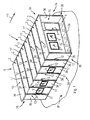
- Figure 1 shows a prefabricated structure 1, usable as a living and/or container unit and locatable on an intended resting surface, for example a portion of ground P.
- the structure 1 is substantially parallepipedon-shaped and comprises a floor 4, a pair of mutually parallel and opposite side walls 5a, 5b, a roof 6 and a further pair of mutually parallel and opposite side walls 7a, 7b (of the latter Figure 1 shows only the front wall 7a).
- an inlet opening 7c provided with a door 8, by means of which it is possible to enter the unit 1.
- the end walls 7a, 7b and/or in the side walls 5a, 5b there are comprised windows 9, each of which is quadrilateral-shaped and is provided with a frame on which a sheet of glass or other suitable transparent material is fitted.
- the unit 1 is made by reciprocally aligning, according to an intended assembly direction F1, and then mutually connecting a plurality of tubular elements 2.
- Each tubular element 2 is parallelpipedon-shaped and is made of panels of known type, made of composite material and such as to ensure that the structure 1 has suitable insulating and mechanical resistance properties.
- Each tubular element 2 comprises a base panel 3a, that is horizontally positionable so as to form a corresponding portion of the floor 4 when the tubular element 2 is rested on the portion of ground P to assemble the unit 1.
- the floor 4 may comprise a plurality of slab elements 11 that are mutually adjacent and fixed to the underlying base panels base 3a of the tubular elements 2. From opposite side borders 30 of the base panel 3a a pair of side panels 3b projects vertically 3c that are mutually parallel and arranged for forming corresponding portions of the pair of side walls 5a, 5b.
- Each tubular element 2 is completed by an end panel 3d, that is parallel to and opposite the base panel 3a and forms a corresponding portion of the roof 6 when the unit 1 is assembled.
- the tubular elements 2 intended for forming the end walls 7a, 7b of the unit 1 comprise further panels defining the end walls 7a, 7b.
- Figure 1 shows a front panel 10 forming the front wall 7.
- the panels in which the inlet opening 7c and/or the windows 9 are received are provided with suitable frame means that are not shown that enable the door 8 and/or the windows 9 to be fitted in the corresponding panel.
- tubular elements 2 are provided comprising side panels 3b, 3c and/or terminal panels 3d that are glass pane-shaped. This is particularly useful, for example, if the structure 1 is used as an office.
- tubular elements 2 are provided comprising side panels 3b, 3c that are hinged on the underlying base panels 3a and on the end panels 3d above, so as to be rotatable around a side border. In this way, once the structure 1 has been assembled the hinged side panels 3b, 3c can be used directly as doors.
- each tubular element 2 In order to assembly each tubular element 2, connecting elements 29, shown in Figure 8 , are used.
- Each connecting element 29 is made in the shape of a metal profiled section having an approximately U-shaped cross section and comprises a lesser face 29a, a greater face 29c and a supporting face 29b.
- the supporting face 29b and the greater face 29c are mutually parallel and arranged transversely to the lesser face 29a.
- threaded holes 31 are obtained, arranged for receiving fixing screws 32, only one of which is shown (by a dotted line) in Figure 8 .
- a pair of connecting elements 29 is fixed to the side borders 30 of each base panel 3a, so that, in use, the lesser face 29a is parallel to the corresponding side edge 30 and opposite the latter, the greater face 29c faces the portion of ground P (on which the base panel 3a rests) and the supporting face 29b faces in an opposite direction to the portion of ground P.
- the panel 3b, 3c After positioning a side panel 3b, 3c so that a side edge (not shown) of the latter rests on the supporting face 29b, the panel 3b, 3c is fixed to the underlying connecting element 29, and thus to the adjacent base panel 3a, by means of the fixing screws 32.
- the latter traverse the threaded holes 31 of the connecting elements 29 and are received in threaded blind holes (which are not shown) obtained in the side panels 3b, 3c.
- further fixing means which is not shown
- the side panels 3b, 3c of each tubular element 2 are fixed to the corresponding end panel 3d.
- the end panel 3d is provided with a pair of connecting elements 29, by means of which the end panel 3d is fixed to the underlying side panels 3b, 3c according to a procedure that is similar to the one disclosed above.
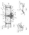
- each fixing device 12 comprises a pair of profiled sections 13a, 13b, made of metal or of another suitable material.
- two adjacent side panels 3b, or 3c forming the side walls 5a, 5b of the unit 1) and/or two adjacent end panels 3d (forming the roof 6 of the unit 1) are mutually connected by a fixing device 12.
- Each panel 3b, 3c, 3d has a composite structure, being formed peripherally by cladding slabs18, made of a suitable material, for example fibreglass, and enclosing an internal layer 20.
- the latter comprises a suitable insulating material, for example expanded polyurethane.
- reinforcing elements 19 are located, for example of the profiled sections in fibreglass, that increase the mechanical resistance properties of the panel 3b, 3c, 3d.
- the panels 3a forming the floor 4 of the unit 1 have the same composite structure disclosed above.
- anchoring elements 21 are also located, in which threaded holes are received (which are not shown). Each anchoring element 21 is immersed in the internal layer 20 and is applied to a corresponding internal surface 18a of the adjacent cladding slab 18.
- Each profiled section 13a, 13b has a substantially L-shaped cross section and comprises a lesser branch 14 and a greater branch 15, arranged transversely to one another. From a border of the greater branch 15 opposite the lesser branch 14 an anchoring branch 16 projects obliquely that, once the fixing device 12 is assembled, enables a guard element 17 to be anchored on the latter.
- through holes 23 are obtained that are usable for mutually connecting the two profiled sections 13a, 13b of each pair by fixing means of known type, for example a nut 24 and a corresponding screw 25 (shown by a dotted line). Similar through holes 23 are obtained in the greater branch 15 and are usable for fixing each profiled section 13a, 13b to the corresponding anchoring element 21 of the underlying panel 3b, 3c, 3d by means of further screws 26 (shown by a dotted line).
- the tubular elements 2 are first positioned so that the respective base panels 3a are in contact with the portion of ground P and the respective side panels 3b, 3c are aligned along the direction F1.
- the floor 4, the side walls 5a, 5b and the roof 6 of the unit 1 to be assembled are defined ( Figure 1 ).
- the profiled sections 13a, 13b of each pair are arranged vertically (at the side walls 5a, 5b), or horizontally (at the roof 6), so that the respective lesser branches 14 mate mutually and the corresponding through holes 23 of the lesser branches 14 are aligned, the respective greater branches 15 rest on the cladding slabs 18 of the underlying panels 3b, 3c, 3d and the through holes 23 of the greater branches 15 are aligned on corresponding through holes 22 ( Figure 8 ) obtained in the thickness of the panels 3b, 3c, 3d.
- the lesser branches 14 are adjacent to one another and aligned on the corresponding connecting zone F, whilst the greater branches 15 face directions that are opposite and parallel to the panels 3b, 3c, 3d.
- the lesser branches 14 are mutually connected by nuts 24 and screws 24 so as to connect mutually the profiled sections 13a, 13b of each pair, and by the further screws 26 the greater branches 15 are fixed to the panels 3b, 3c, 3d, i.e. to the anchoring elements 21 of the latter.
- the fixing devices 12 enable the adjacent tubular elements 2 to mate mutually in a substantially complete manner, thus preventing interstices forming that are such as to enable water to infiltrate inside the unit 1, as occurs, on the other hand, in known prefabricated units that are assembled using screw tie rods.
- interpose sealing elements for example washers 28 of known type, between the cladding slabs 18 of the panels 3b, 3c, 3d and the greater branches 15. In this way, the seal of the unit 1 in relation to water infiltrations, which is per se greater than that of known prefabricated units, can be increased further.
- Figure 7 shows an embodiment of the fixing device 12 in which a spacing element 34 is interposed between the two profiled sections 13a and 13b.
- the spacing element 34 is bar-shaped, having a cross section of quadrilateral shape, it extends longitudinally and parallel to the two profiled sections 13a, 13b and is interposed between the lesser branches 14 of the latter.
- the two profiled sections 13a and 13b shown in Figure 7 have the same structure as the profiled sections 13a and 13b disclosed previously with respect to Figures 2 and 3 . Consequently, the fixing device 12 shown in Figure 7 is assembled by means of a procedure that is similar to that previously disclosed with reference to the fixing device 12 shown in Figure 2 , so as to obtain the assembly configuration A ( Figure 7 ).
- the spacing element 34 has a length that is significantly less than the length of the profiled sections 13a, 13b. Consequently, between the two profiled sections 13a, 13b there can be interposed a plurality of spacing elements 34 that are mutually aligned and spaced.
- the shape of the cross section of the spacing element 34 is circular or generally polygonal.
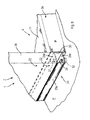
- FIGS 5 and 6 show another embodiment of the fixing device 12, in which one of the two profiled sections 13a, 13b is replaced by a profiled section 13c provided with an abutting portion 33.
- the profiled section 13c has a substantially L-shaped cross section and comprises a lesser branch 14 and a greater branch 15, arranged transversely to one another.
- the abutting portion 33 is shelf-shaped and extends along the entire length of the lesser branch 14.
- the abutting portion 33 protrudes from the lesser branch 14 in a position opposite the greater branch 15 and is parallel to the latter.
- the shape and dimensions of the abutting portion 33 are such as to enable the latter to receive and lock a free border 35 of the lesser branch 14 of the profiled section 13a, or 13b.
- slots 36 are obtained that have an elongated shape and are arranged transversely to the greater branch 15.
- the lesser branch 14 of the profiled section 13c is provided with both slots 36 and through holes 23.
- the lesser branch 14 of the profiled section 13c is provided with through holes 23 and is devoid of slots 36.
- the profiled section 13c is particularly useful if one or more panels, in particular the end panels 3d forming the roof 6, are curved transversely to the assembly direction F1, so as to be, for example, convex towards the exterior with respect to the respective tubular element 2.
- the profiled section 13c is mounted on the curved end panel 3d whereas a corresponding profiled section 13a, 13b is mounted on the adjacent end panel 3d.
- the curved end panel 3d by exerting suitable pressure on the curved end panel 3d, the latter is deformed (flattened) so as to take the profiled section 13c to the corresponding profiled section 13a, 13b until the abutting portion 33 of the profiled section 13c stops against the free border 35 of the profiled section 13a, 13b, i.e. until the profiled section 13c is at the same level as the corresponding profiled section 13a, 13b.
- the lesser branch 14 and/or the greater branch 15 of the profiled sections 13a, 13b are provided with slots 36.
- a guard element 17 can be fixed thereupon that is made in the shape of a metal profiled section.
- the cross section of the protecting element 17 is shaped so as to enable the protecting element 17 to adapt suitably to the shape and to the dimensions of the profiled sections 13a, 13b, 13c forming the fixing device 12 ( Figure 2 ; Figure 5; Figure 7 ).
- the cross section of the protecting element 17 comprises a convex central portion 17a and a pair of lateral portions 17b, 17c ( Figure 4 ). Between the convex central portion 17a and each of the lateral portions 17b, 17c, there is defined an anchoring portion 27.
- the anchoring portions 27 are convex and can engage the anchoring branches 16 comprised in the profiled sections 13a, 13b, 13c. In this way, when on each assembled fixing device 12 the corresponding protecting element 17 is fitted, the latter completely covers the profiled sections 13a, 13b, 13c and engages the respective anchoring branches 16.
- the protecting element 17 performs both a safety function and a decorative function. In fact, the protecting element 17 prevents a user from coming accidentally into contact with the shape corners with which the profiled sections 13a, 13b, 13c are provided and which could be the cause of accidents. At the same time, the protecting element 17 has a pleasant shape that contributes to improving the external appearance of the unit 1.
- the protecting element 17 has a square or polygonal cross section.
- the unit 1 can be equipped with the elements necessary to perform the function, such as tables, seats, beds and other furniture elements, and with possible electrical and/or water systems.
- the unit 1 thereby obtained, owing to the fixing devices 12, has excellent sealing properties in relation to atmospheric agents and can therefore be used effectively as a living and/or container unit even in adverse climatic and meteorological conditions.
Landscapes
- Engineering & Computer Science (AREA)
- Mechanical Engineering (AREA)
- Architecture (AREA)
- Civil Engineering (AREA)
- Structural Engineering (AREA)
- Physics & Mathematics (AREA)
- Electromagnetism (AREA)
- Prostheses (AREA)
- Tents Or Canopies (AREA)
Applications Claiming Priority (2)
| Application Number | Priority Date | Filing Date | Title |
|---|---|---|---|
| ITMO20070093 ITMO20070093A1 (it) | 2007-03-16 | 2007-03-16 | Struttura assemblabile |
| ITMO20070247 ITMO20070247A1 (it) | 2007-07-26 | 2007-07-26 | Struttura assemblabile |
Publications (2)
| Publication Number | Publication Date |
|---|---|
| EP1985778A2 true EP1985778A2 (fr) | 2008-10-29 |
| EP1985778A3 EP1985778A3 (fr) | 2010-12-22 |
Family
ID=39745411
Family Applications (1)
| Application Number | Title | Priority Date | Filing Date |
|---|---|---|---|
| EP08152713A Withdrawn EP1985778A3 (fr) | 2007-03-16 | 2008-03-13 | Structure pouvant être assemblée |
Country Status (1)
| Country | Link |
|---|---|
| EP (1) | EP1985778A3 (fr) |
Cited By (3)
| Publication number | Priority date | Publication date | Assignee | Title |
|---|---|---|---|---|
| CN109114079A (zh) * | 2018-09-21 | 2019-01-01 | 中国五冶集团有限公司 | 一种钢板结构的连接机构 |
| ES2891424A1 (es) * | 2020-07-16 | 2022-01-27 | Garofoli Spa | Sistema de panelado del shelter s-788/g |
| CN115072188A (zh) * | 2022-07-28 | 2022-09-20 | 山东京阳科技股份有限公司 | 一种海洋运输用沥青储存装置 |
Family Cites Families (4)
| Publication number | Priority date | Publication date | Assignee | Title |
|---|---|---|---|---|
| DE3023972A1 (de) * | 1980-06-26 | 1982-01-21 | Dyna-Plastik-Werke Gmbh, 5060 Bergisch Gladbach | Bausatz fuer einen behaelter, insbesondere als nothaus |
| WO1994013900A1 (fr) * | 1992-12-04 | 1994-06-23 | J. & B. Contracting Pty. Limited | Enceinte anti-feu |
| GB0021376D0 (en) * | 2000-08-31 | 2000-10-18 | Marche Peter De La | Modular building |
| US6530630B2 (en) * | 2001-07-13 | 2003-03-11 | Carrier Corporation | Panel seal for an air handling unit |
-
2008
- 2008-03-13 EP EP08152713A patent/EP1985778A3/fr not_active Withdrawn
Cited By (4)
| Publication number | Priority date | Publication date | Assignee | Title |
|---|---|---|---|---|
| CN109114079A (zh) * | 2018-09-21 | 2019-01-01 | 中国五冶集团有限公司 | 一种钢板结构的连接机构 |
| ES2891424A1 (es) * | 2020-07-16 | 2022-01-27 | Garofoli Spa | Sistema de panelado del shelter s-788/g |
| CN115072188A (zh) * | 2022-07-28 | 2022-09-20 | 山东京阳科技股份有限公司 | 一种海洋运输用沥青储存装置 |
| CN115072188B (zh) * | 2022-07-28 | 2022-11-01 | 山东京阳科技股份有限公司 | 一种海洋运输用沥青储存装置 |
Also Published As
| Publication number | Publication date |
|---|---|
| EP1985778A3 (fr) | 2010-12-22 |
Similar Documents
| Publication | Publication Date | Title |
|---|---|---|
| KR101527077B1 (ko) | 단열 커튼월 창호 시스템 | |
| US6601362B1 (en) | Variable load capacity construction components for patio pool enclosures | |
| KR102157195B1 (ko) | 조립식 단열패널 | |
| EP2844802B1 (fr) | PANNEAU SANDWICH et PROCÉDÉ DE CONSTRUCTION D'UN TEL PANNEAU SANDWICH | |
| JP2012052325A (ja) | 木製独立柱 | |
| US20220009196A1 (en) | Construction panel for use as self-supporting wall panel or roof panel | |
| KR101450628B1 (ko) | 단열 커튼월 창호 시스템 | |
| EP2273040B1 (fr) | Cadre de clôture | |
| DE10333299B4 (de) | Wärmedämmsystem | |
| JP3375897B2 (ja) | オーニング装置 | |
| KR102533647B1 (ko) | 지붕 시공용 이중 아치패널 조립체 | |
| US20100236168A1 (en) | High Impact Storm Panel | |
| GB2469845A (en) | Thermal insulation structure for conservatory style roofs | |
| JP2004107887A (ja) | 持ち出し手摺 | |
| JP4953482B2 (ja) | 鉄筋コンクリート建物の外断熱外壁に於ける開口部構造 | |
| KR100662106B1 (ko) | 차양장치 및 그 제조방법 | |
| US11965340B2 (en) | Modular type shading facade | |
| EP0474582A1 (fr) | Système de couverture d'un balcon pour la rénovation de bâtiments à multiples étages existants | |
| JPH07229267A (ja) | タイルの取付工法 | |
| WO2024133414A1 (fr) | Dispositif de panneau mural comprenant un panneau mural et un agencement de couplage | |
| ITMO20070247A1 (it) | Struttura assemblabile | |
| NO314952B1 (no) | Fremgangsmåte og anordning for montering av glassfasader | |
| JPS6229571Y2 (fr) | ||
| JP3143284U (ja) | トラス式構造体 | |
| JPH10121638A (ja) | 庇構造 |
Legal Events
| Date | Code | Title | Description |
|---|---|---|---|
| PUAI | Public reference made under article 153(3) epc to a published international application that has entered the european phase |
Free format text: ORIGINAL CODE: 0009012 |
|
| AK | Designated contracting states |
Kind code of ref document: A2 Designated state(s): AT BE BG CH CY CZ DE DK EE ES FI FR GB GR HR HU IE IS IT LI LT LU LV MC MT NL NO PL PT RO SE SI SK TR |
|
| AX | Request for extension of the european patent |
Extension state: AL BA MK RS |
|
| PUAL | Search report despatched |
Free format text: ORIGINAL CODE: 0009013 |
|
| AK | Designated contracting states |
Kind code of ref document: A3 Designated state(s): AT BE BG CH CY CZ DE DK EE ES FI FR GB GR HR HU IE IS IT LI LT LU LV MC MT NL NO PL PT RO SE SI SK TR |
|
| AX | Request for extension of the european patent |
Extension state: AL BA MK RS |
|
| AKY | No designation fees paid | ||
| REG | Reference to a national code |
Ref country code: DE Ref legal event code: R108 |
|
| REG | Reference to a national code |
Ref country code: DE Ref legal event code: R108 Effective date: 20110831 |
|
| STAA | Information on the status of an ep patent application or granted ep patent |
Free format text: STATUS: THE APPLICATION IS DEEMED TO BE WITHDRAWN |
|
| 18D | Application deemed to be withdrawn |
Effective date: 20110623 |